9. Embedded programming
Individual Assignment:
- Read a microcontroller data sheet
- Program your board to do something with as many different programming languages and programming environments as possible
Group Assignment:
- Compare the performance and development workflows for other architectures
INDIVIDUAL ASSIGNMENT
This week I analize the response of the ATTINY44A with Asembler, C++ Native and Arduino IDE.
1. The summarize of Attiny44A
The Attiny44A datasheet we can download in this page.
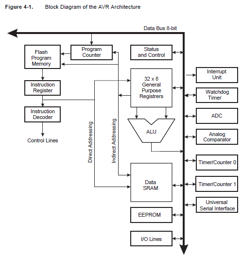
The first information to learn is the internal structure of microcontroller:
We can see the connection of: - Flash Program Memory - Instruction Register - Instruction DEcoder - ALU - Data SRAM - Register - Internal Resources
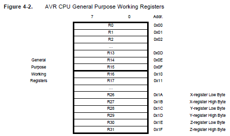
In the figure 4-2 we can see the list of working registers from R0 to R31:
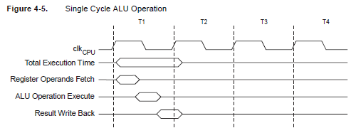
In the Figure 4-5 we can see the Cycle ALU operation, it operation is considerated a cycle.
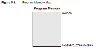
In the Figure 5.1 we can see the address program memory from the Attiny:
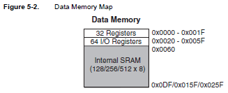
In the Figure 5.2 we can see the address data memory from the Attiny:
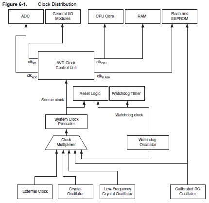
In the Figure 6-1 we can see the Clock Distribution to work the internal resources:
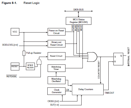
In the Figure 8-1 we can see the Reset Logic to work the internal resources:
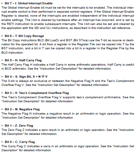
In the following Figure we can see the SREG register to control the Counter Program:
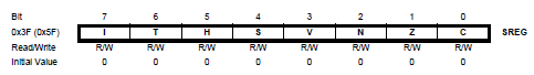
In the following figure we can see the SREG explained, bit to bit:
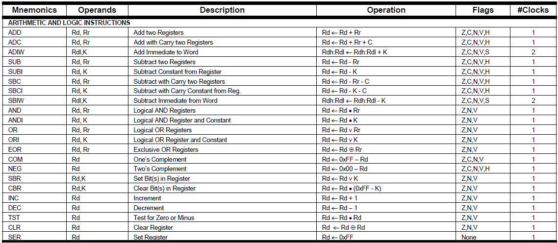
The microcontroller has Instruction in Assembler to work, with ARITHMETIC and LOGIC INSTRUCTIONS, that instruction are executing on ALU unit:
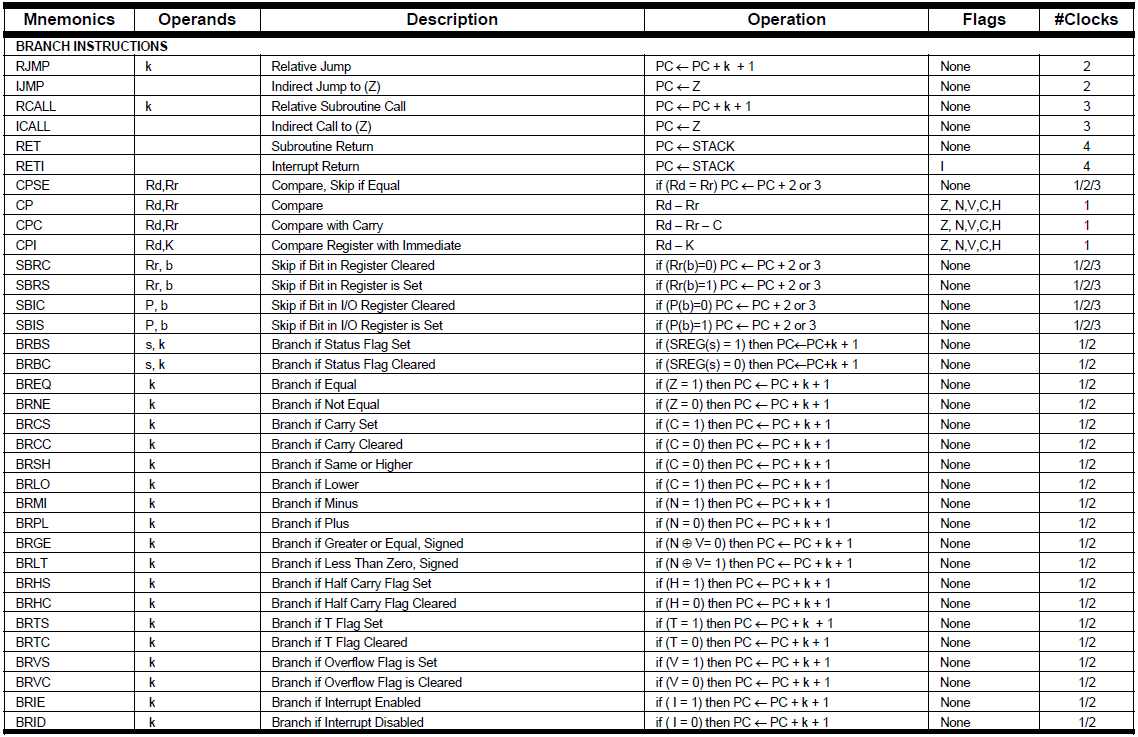
Also the microcontroller has BRANCH INSTRUCTIONS:
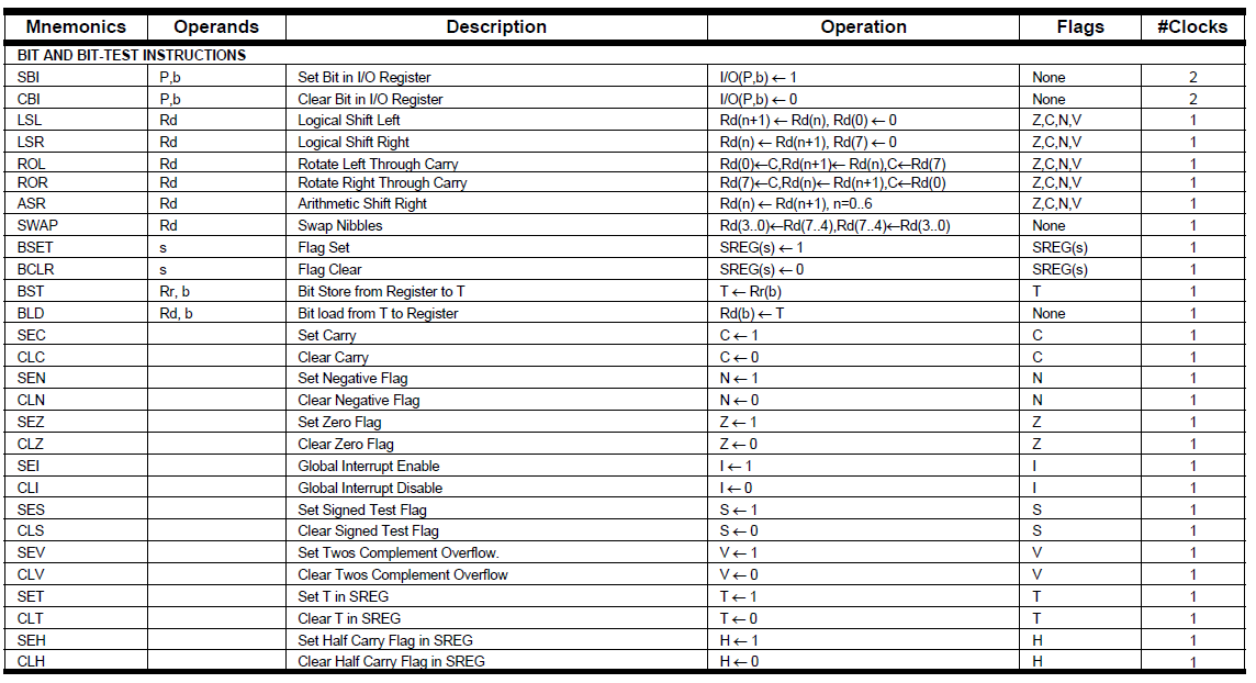
Also the microcontroller has BIT and BIT TEST INSTRUCTIONS:
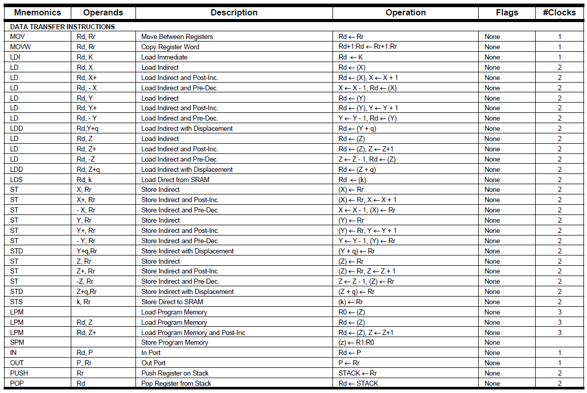
Also the microcontroller has DATA TRANSFER INSTRUCTIONS:
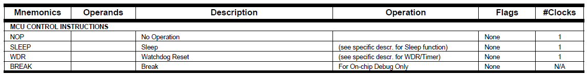
Also the microcontroller has MCU CONTROLS INSTRUCTIONS:
2. Programming in Native Assembly in Atmel Studio
The software Atmel Studio 7.0 where you can download the installer and install the software.
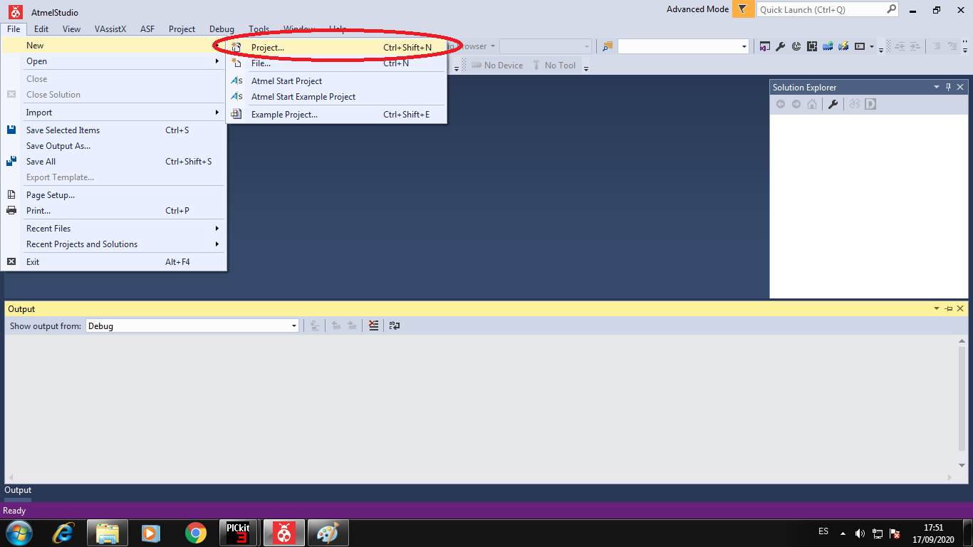
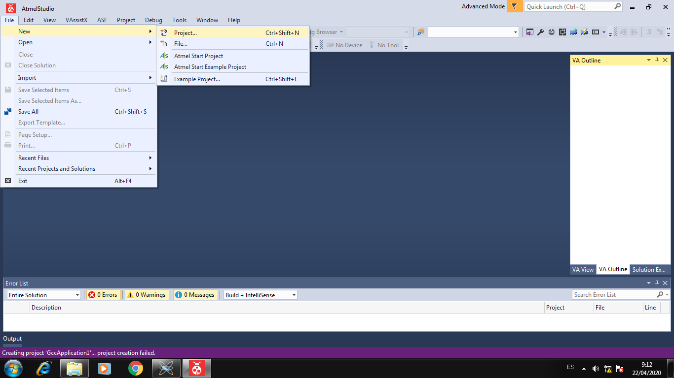
I create a new project:
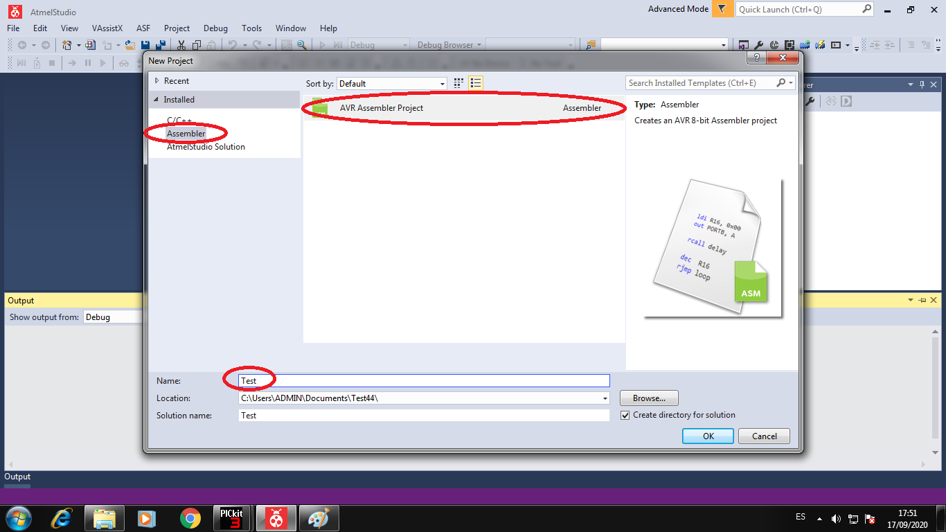
Choose the Assembler project and write the name project:
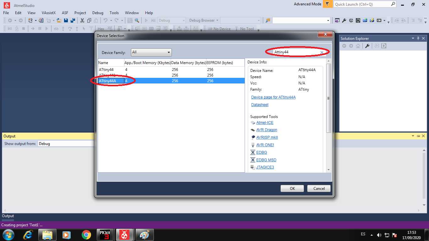
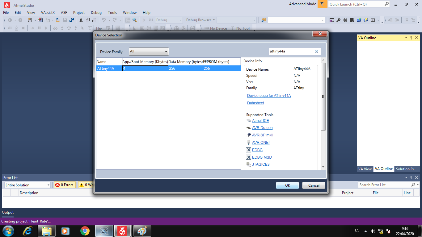
Choose the Attiny44A microcontroller in the search area, and click and OK button to create the project:
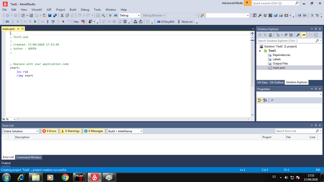
We can see the initial code to project, but I change to Blink Led with assembler code:
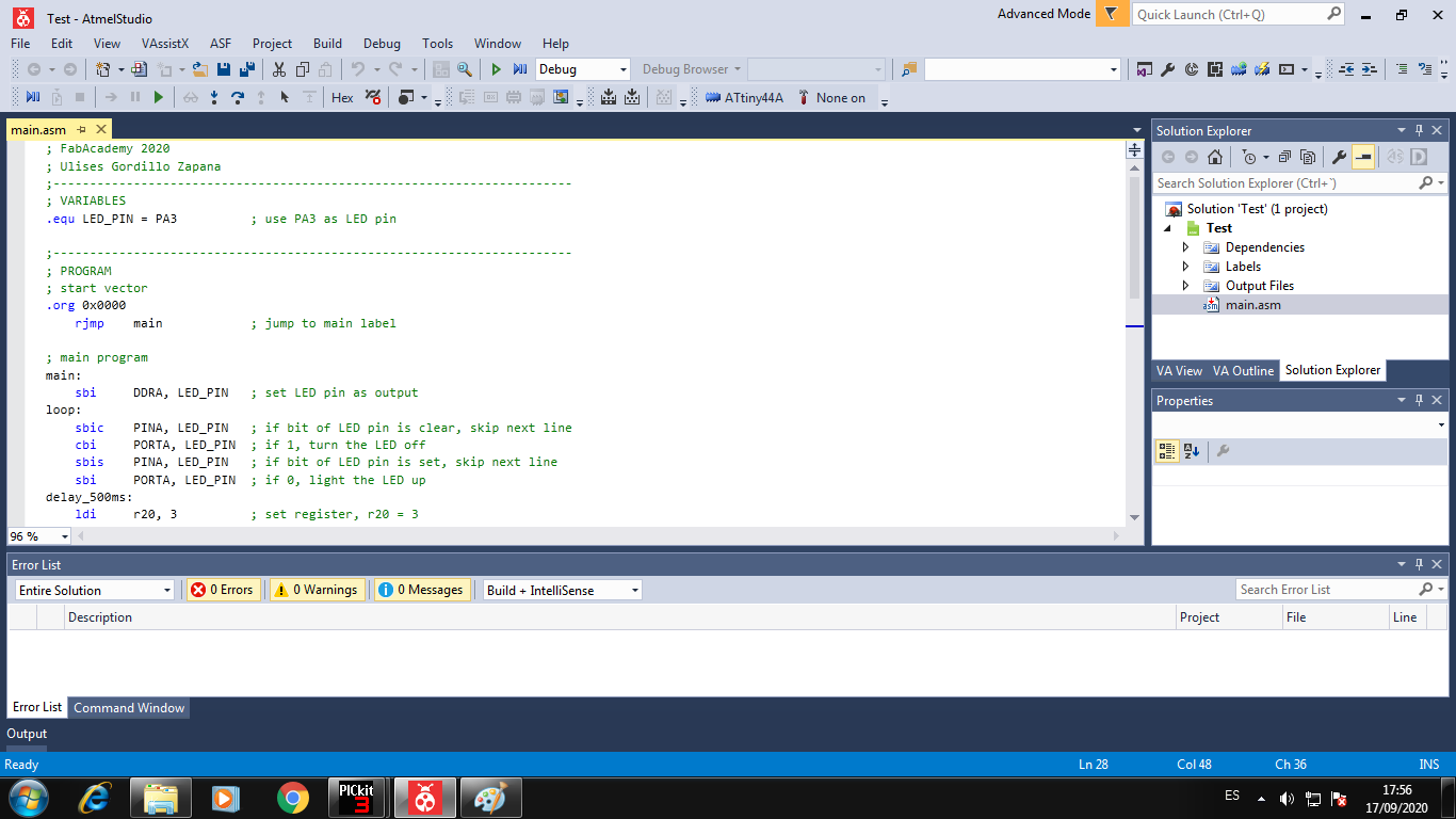
Write the code to Blink Led in PA3 pin to Attiny44A:
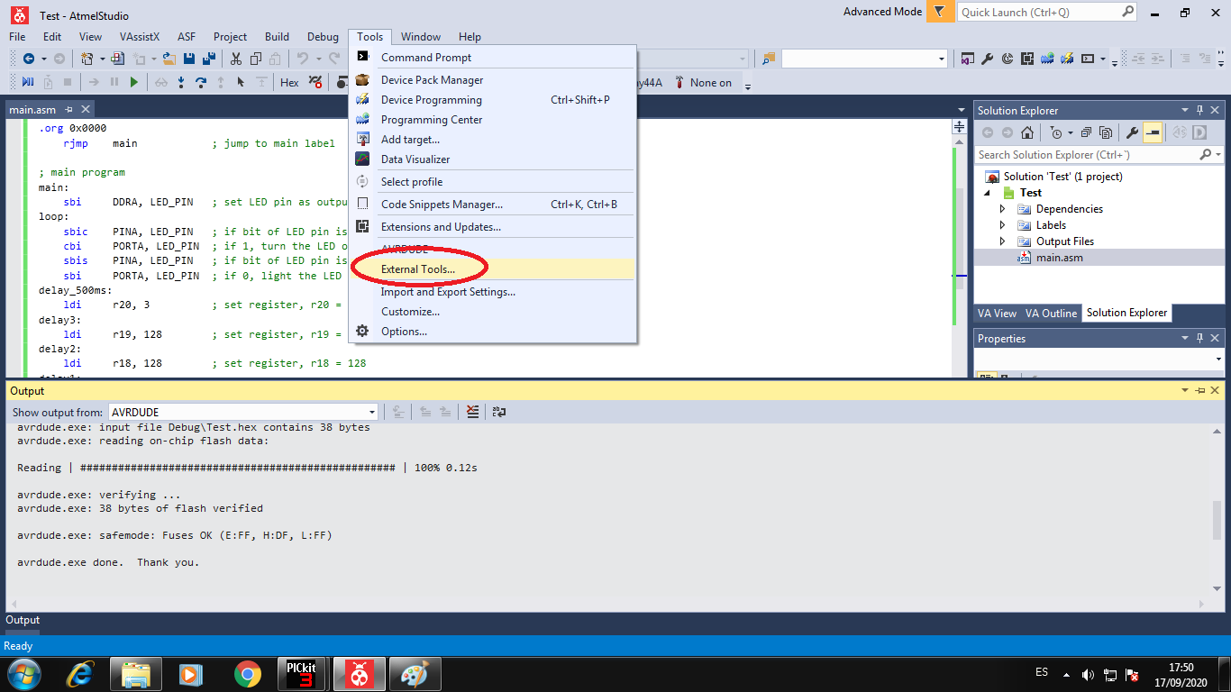
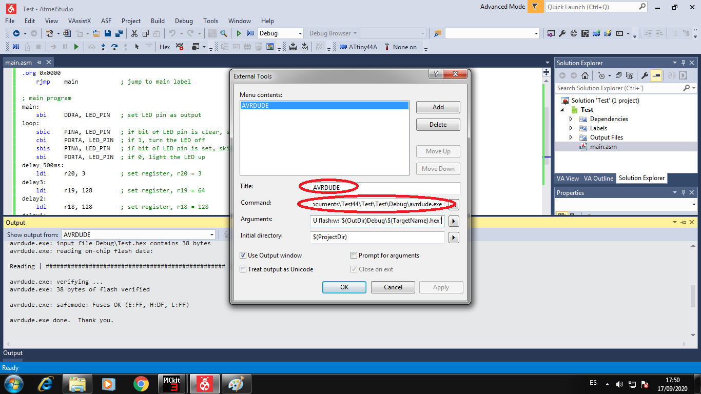
To use the USPtiny programmer we configurate in the menu Tools -> External Tools:
Add a external tools with:
- Title: Name of tool -> AVRDUDE
- Command: Address of the tool -> C:\Avrdude\avrdude.exe
- Arguments: To program -> -C C:\Avrdude\avrdude.conf -v -p attiny44 -c usbtiny -U flash:w:”$(OutDir)Debug\$(TargetName).hex”:i
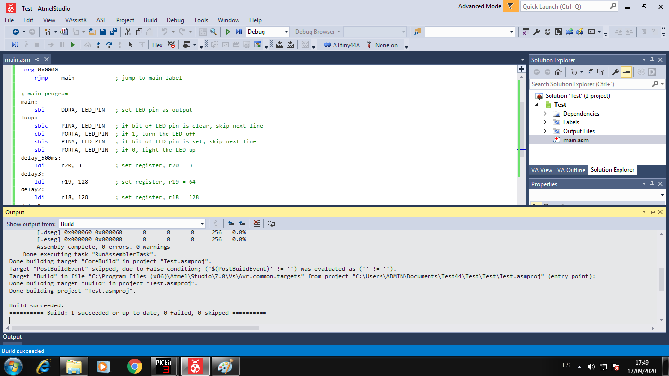
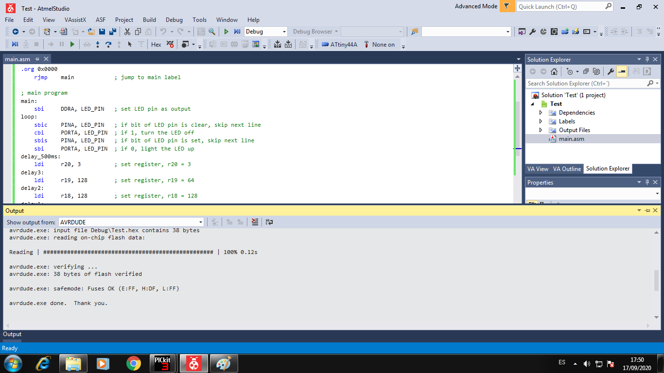
Now I build the project to create the HEX file:
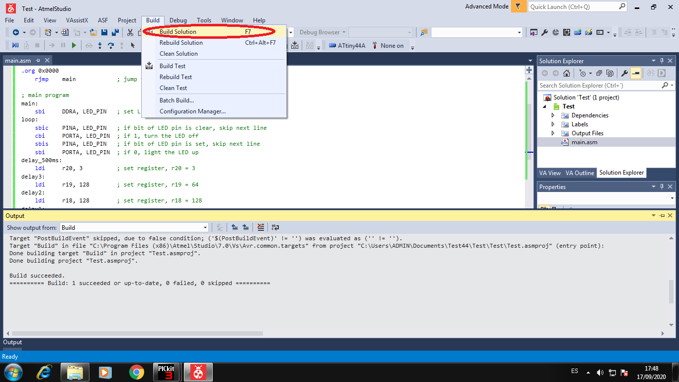
The project is compiled and build the Hex file is successed:
Now we can load the HEX file with the USBtiny in the external tools:
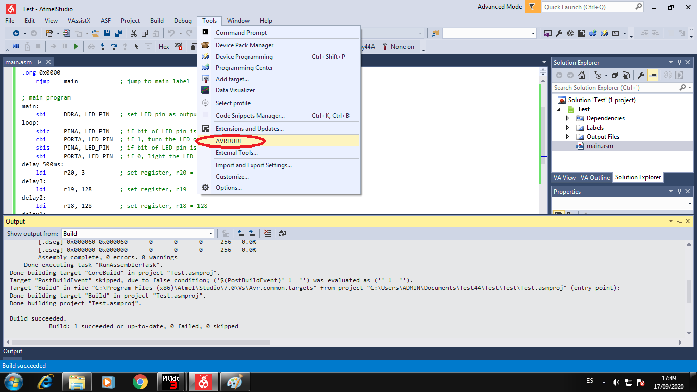
The Hex file is loaded successful
3. Programming in Native C++ in Atmel Studio
When we programming with the Atmel Studio Platform the proccess to create Project in C++ is same to ASM Project, then this part we do not explain because it is repeat.
After we create the project we can program in C++ with libraries from AVR microcontrollers, it is insatalled in Native software Atmel Studio.
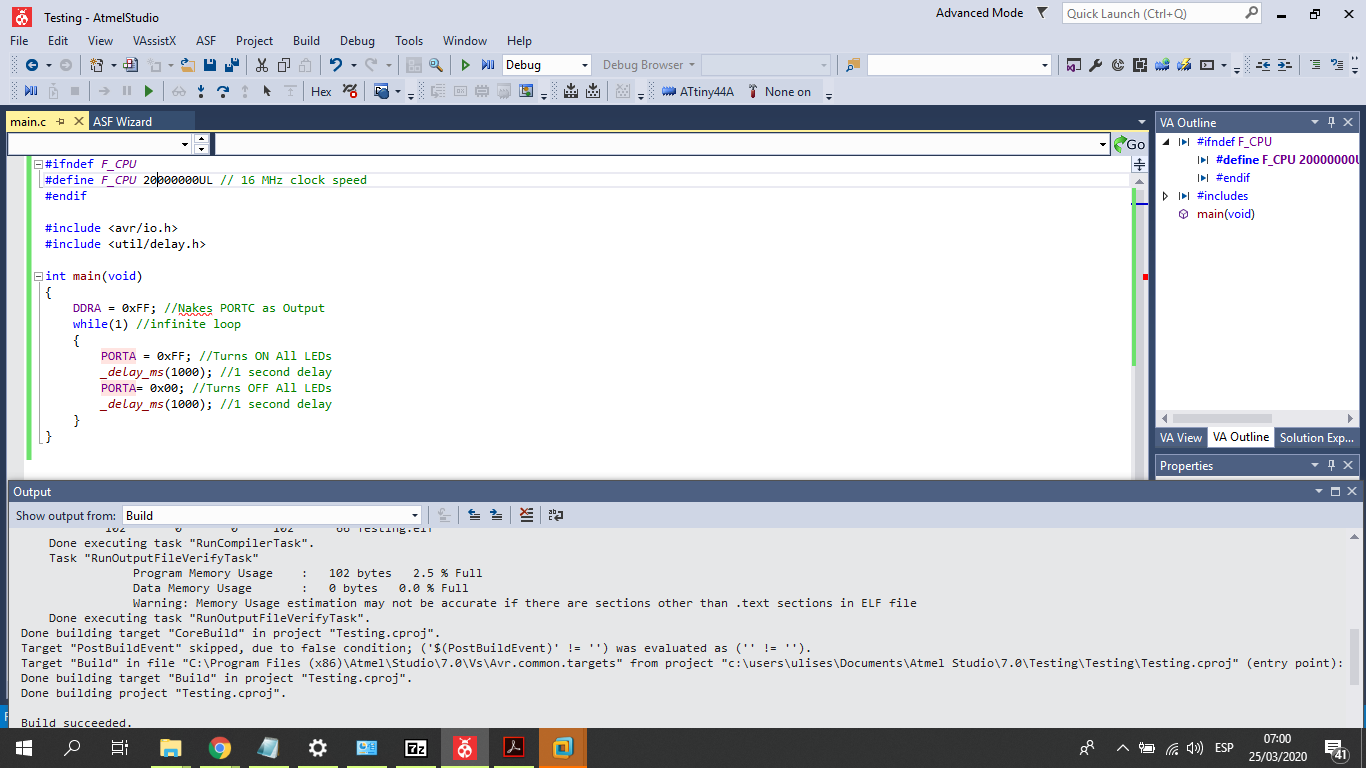
Then we can see the program to create a BLINK process to LED:
Choose the C++ project to create:
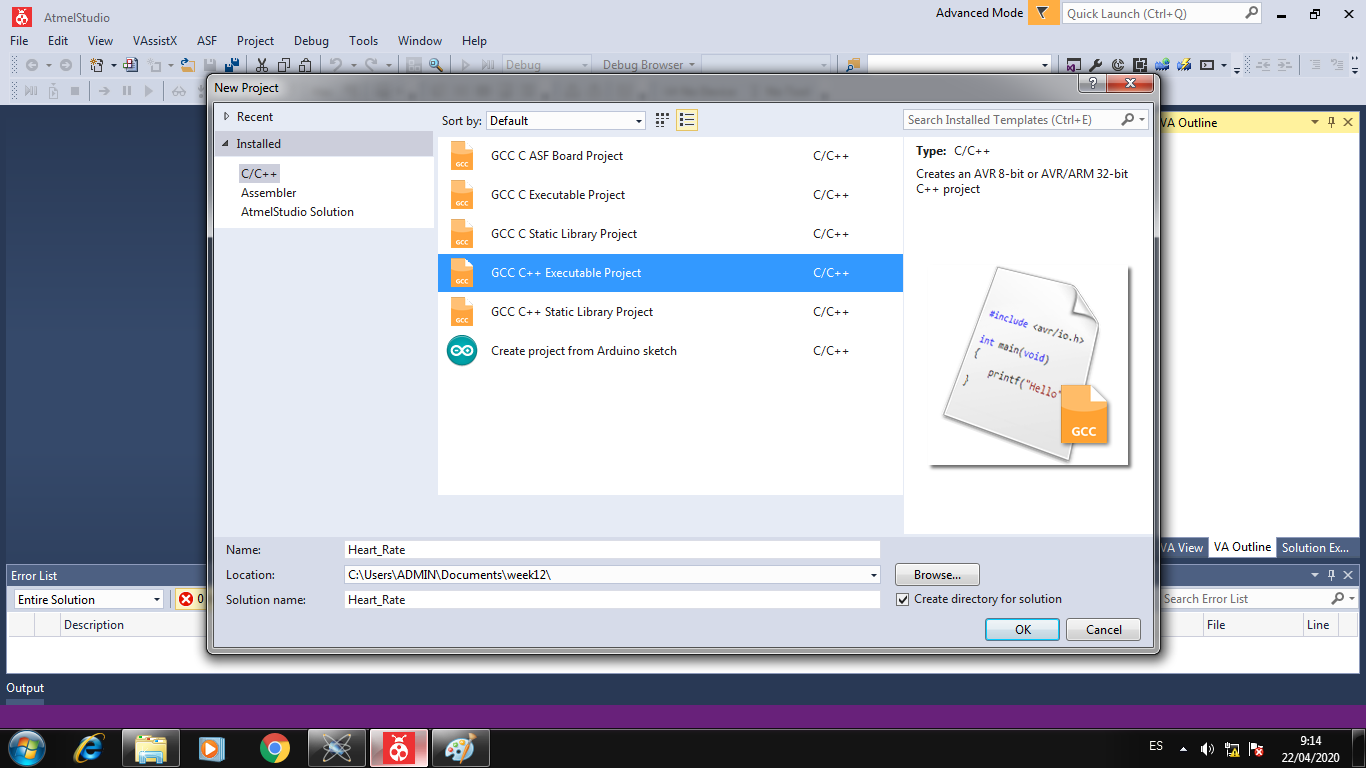
Choose the Attiny 44 as microcontroller:
Write the program to blink with the libraries of Atmel Studio Software:
4. Programming in Arduino IDE
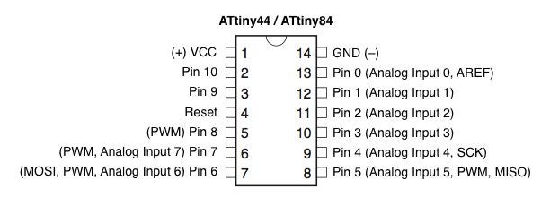
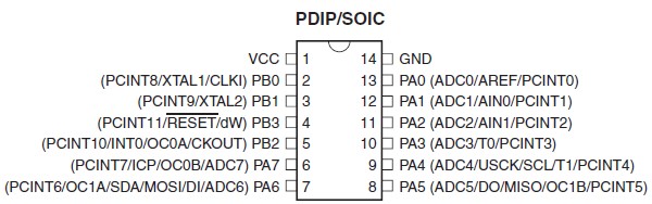
To program in Arduino IDE the Attiny44 microcontroller, we must have the Attiny Compiler added in Arduino IDE0, and then we can learn the number pins:
We design the following program to Blink example to Attimy44A:
//****************************************************
// Ulises Gordillo Zapana - FabAcademy 2020
//****************************************************
#define pin_tx      8
#define pin_rx      7
#define pin_but     6
#define pin_buz     5
#define pin_cardio  4
#define pin_led     3
#define pin_ldr     A2
#define pin_led_car 1
#define pin_pot     0

// Function SETUP
void setup() {
  pinMode(pin_but,INPUT);
  pinMode(pin_buz,OUTPUT);
  pinMode(pin_cardio,OUTPUT);
  digitalWrite(pin_cardio,HIGH);
  pinMode(pin_led,OUTPUT);
  pinMode(pin_led_car,OUTPUT);
}

// Function LOOP
void loop(){
  digitalWrite(pin_led,HIGH);
  delay(1000);
  digitalWrite(pin_led,LOW);
  delay(1000);
}
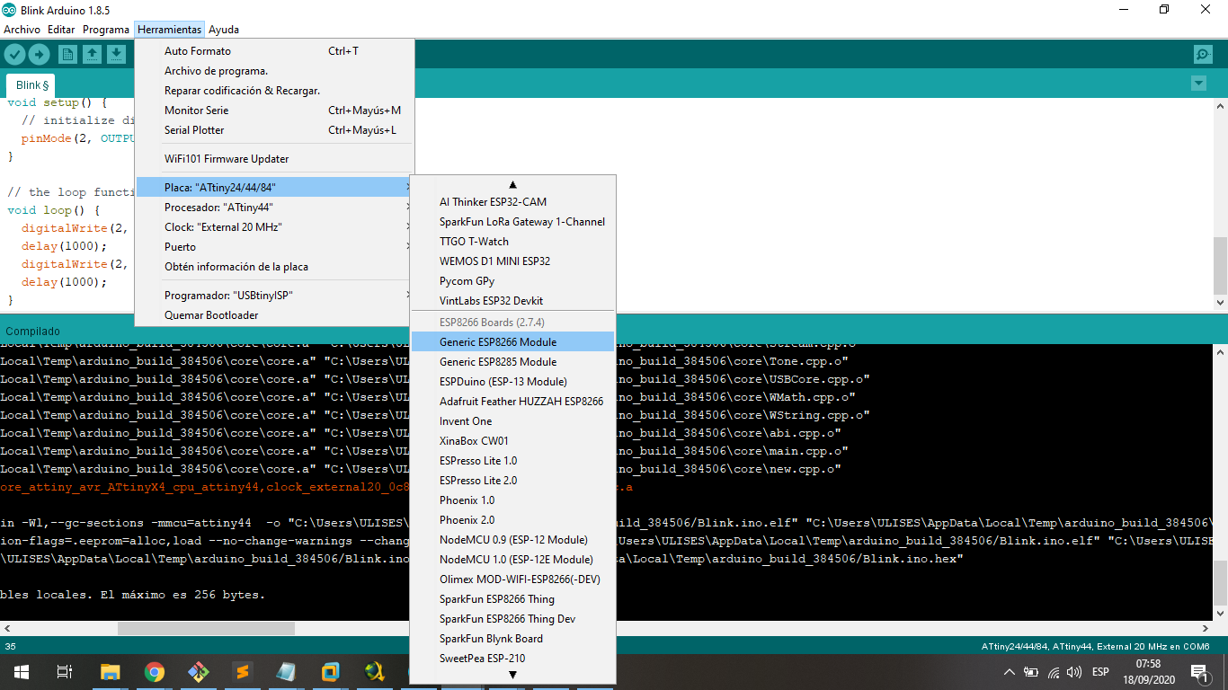
To program Attiny, we must add the Attiny44 resource, and choose the Attiny44 with external crystal of 20MHz
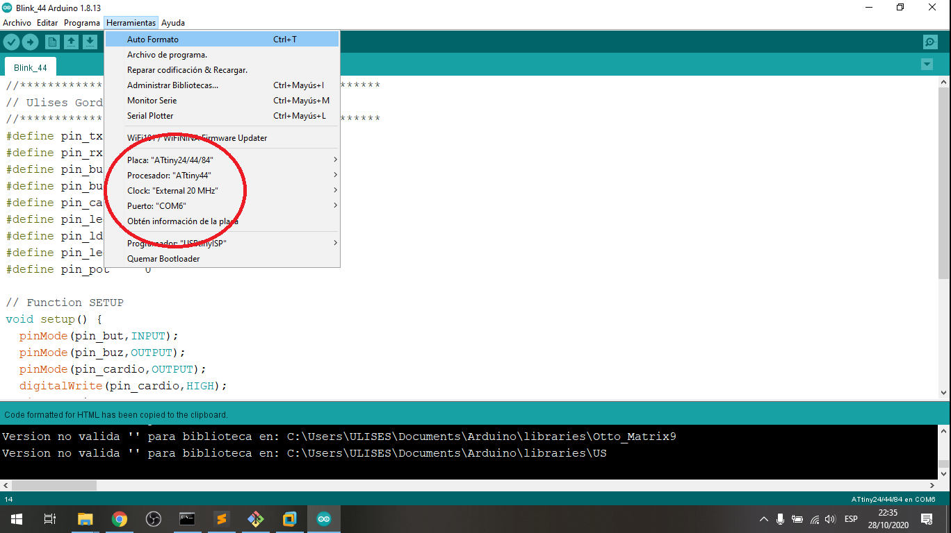
Following we choose the programmer to USBtinyISP:
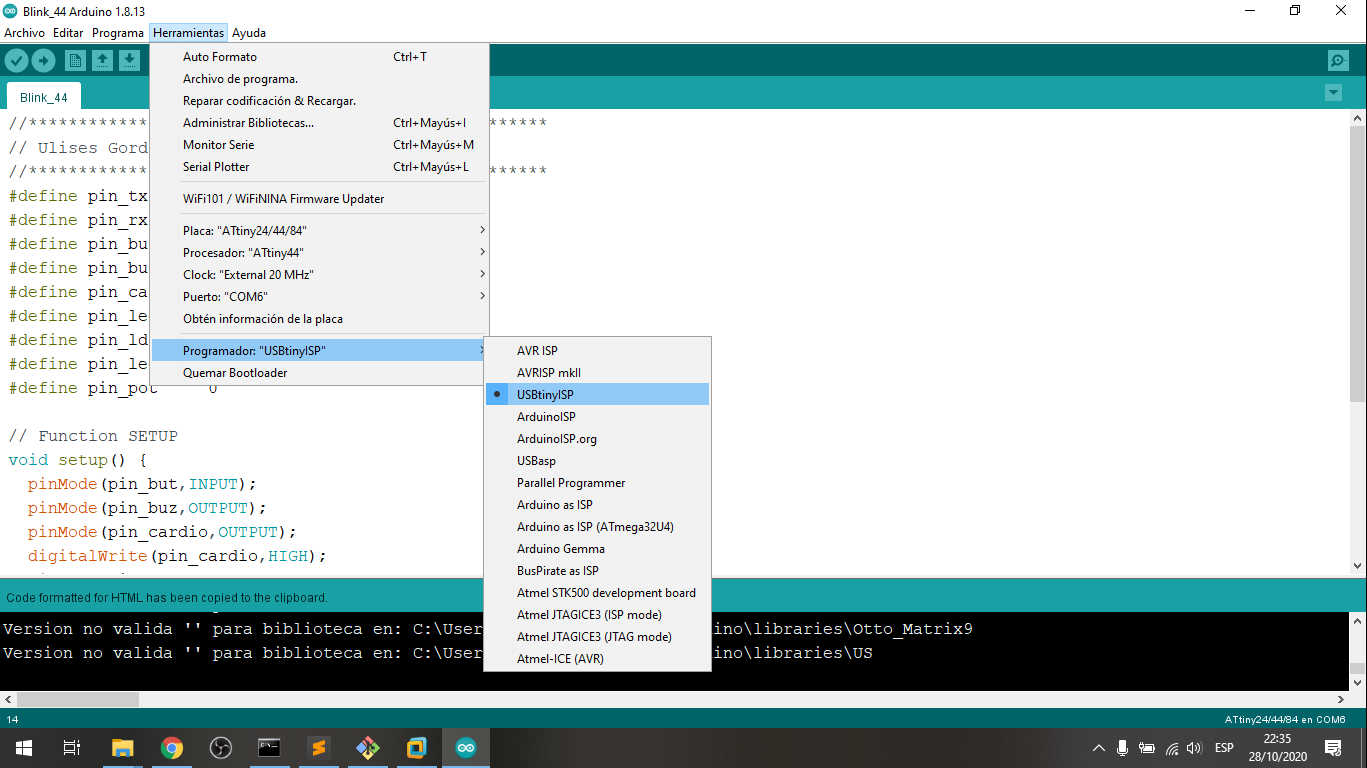
Following we can program with a external programmer as USBtinyISP
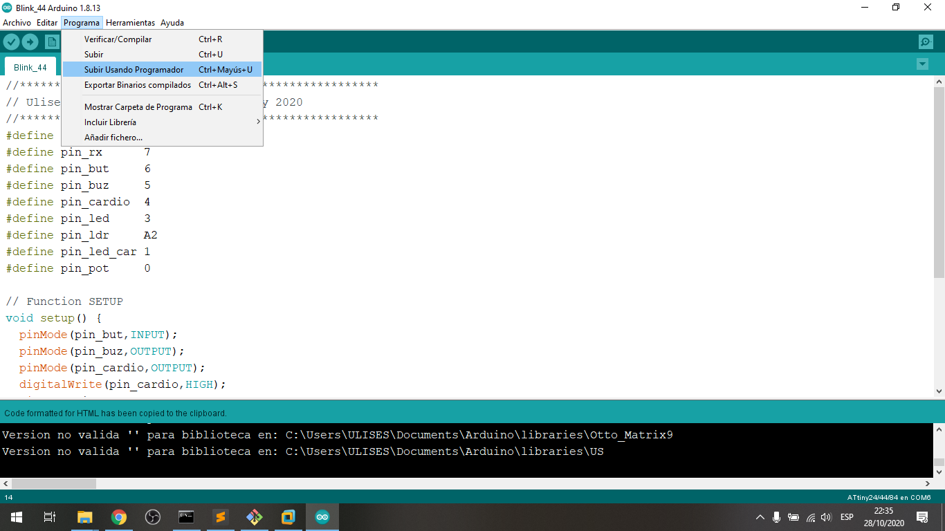
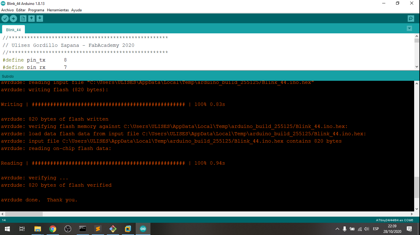
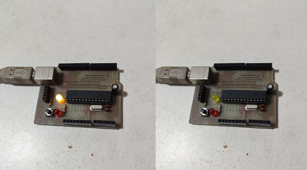
And Finally the microcontroller was programmed with Arduino IDE and USBtinyISP:
5. Project with Ultrasonic Sensor and Attiny44
In this project, the distance from the sensor to a flat object will be measured, which will make the buzzer emit a sound.
The sensor used is the HC-SR04 and the program is as follows:
#define pin_trig  7
#define pin_echo  8
#define pin_buz   4
void setup() {
  pinMode(pin_trig, OUTPUT);    //pin como salida
  pinMode(pin_echo, INPUT);     //pin como entrada
  pinMode(pin_buz, OUTPUT);     //pin como salida
  digitalWrite(pin_buz, HIGH);
  digitalWrite(pin_trig, LOW);  //Inicializamos el pin trigger con 0 logico
}
void loop(){
  long t;                       //tiempo que demora en llegar el ECO
  long d;                       //distancia en centimetros
  digitalWrite(pin_trig, HIGH);
  delayMicroseconds(10);        //Enviamos un pulso de 10us
  digitalWrite(pin_trig, LOW);
  t = pulseIn(pin_echo, HIGH);  //obtenemos el ancho del pulso
  d = t/59;                     //escalamos el tiempo a una distancia en cm
  if (d<10){
    digitalWrite(pin_buz, LOW);
  }
  else{
    digitalWrite(pin_buz, HIGH);
  }
}
We can see how it works in the following video:
GROUP ASSIGNMENT
Compare the performance and development workflows for the following architectures, all in the blink program to compare the delay routines:
- PIC18F2550
- ESP8266
- ESP32
- Attiny44A
1. Comparing the functionality
Table to Blink Process in diferent architectures:
| Architecture | Frecuency | Cycle (seg) | Duty (%) |
|---|---|---|---|
| Ideal | 0.500Hz | 2.000 s | 50.0 % |
| Microchip PIC18F2550 in C | 0.508Hz | 1.966 s | 50.8 % |
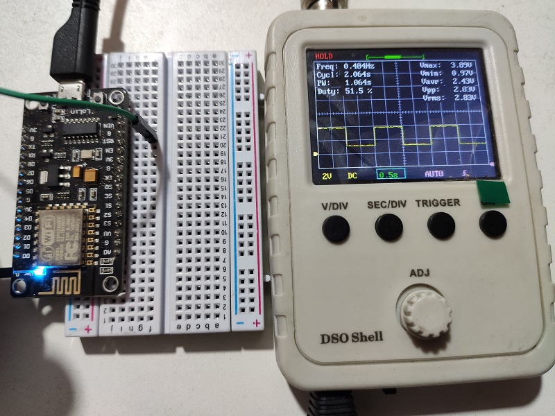
| Espressif ESP8266 in C | 0.484Hz | 2.064 s | 51.5 % |
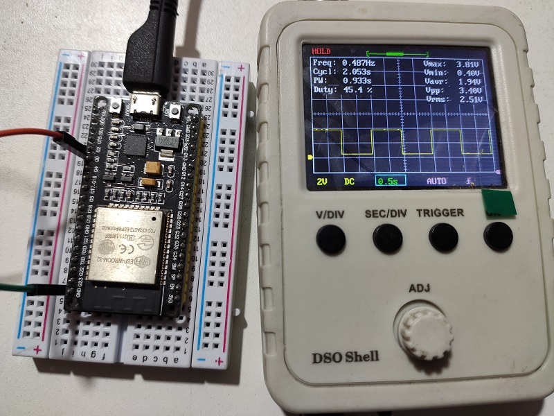
| Espressif ESP32 in C | 0.487Hz | 2.053 s | 45.4 % |
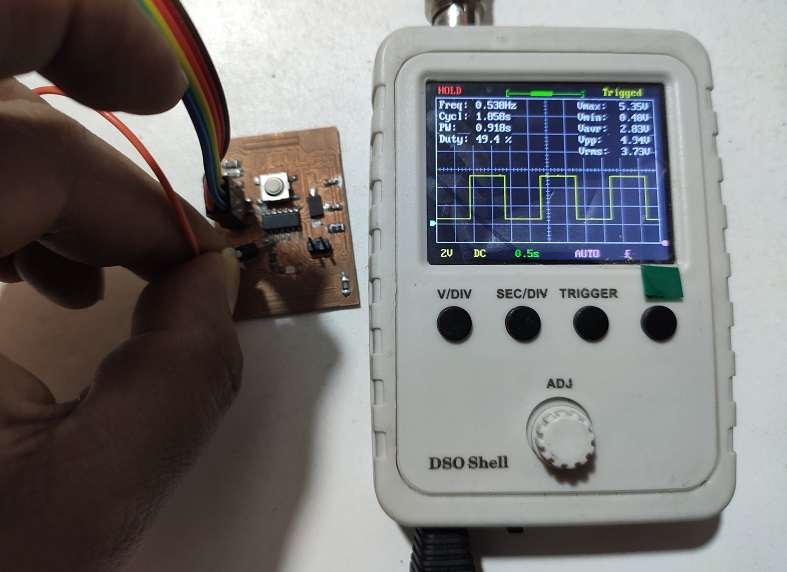
| AVR Attiny44A in C | 0.538Hz | 1.858 s | 50.8 % |
2. Testing the PIC18F2550 in C++
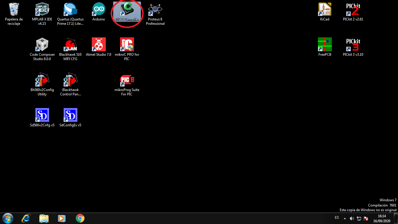
In this part I program the PIC18F2550 from Microchip Company in C++ and program with the PICKIT 3 programmer; We can download the CCS C for PIC Software in http://www.ccsinfo.com/
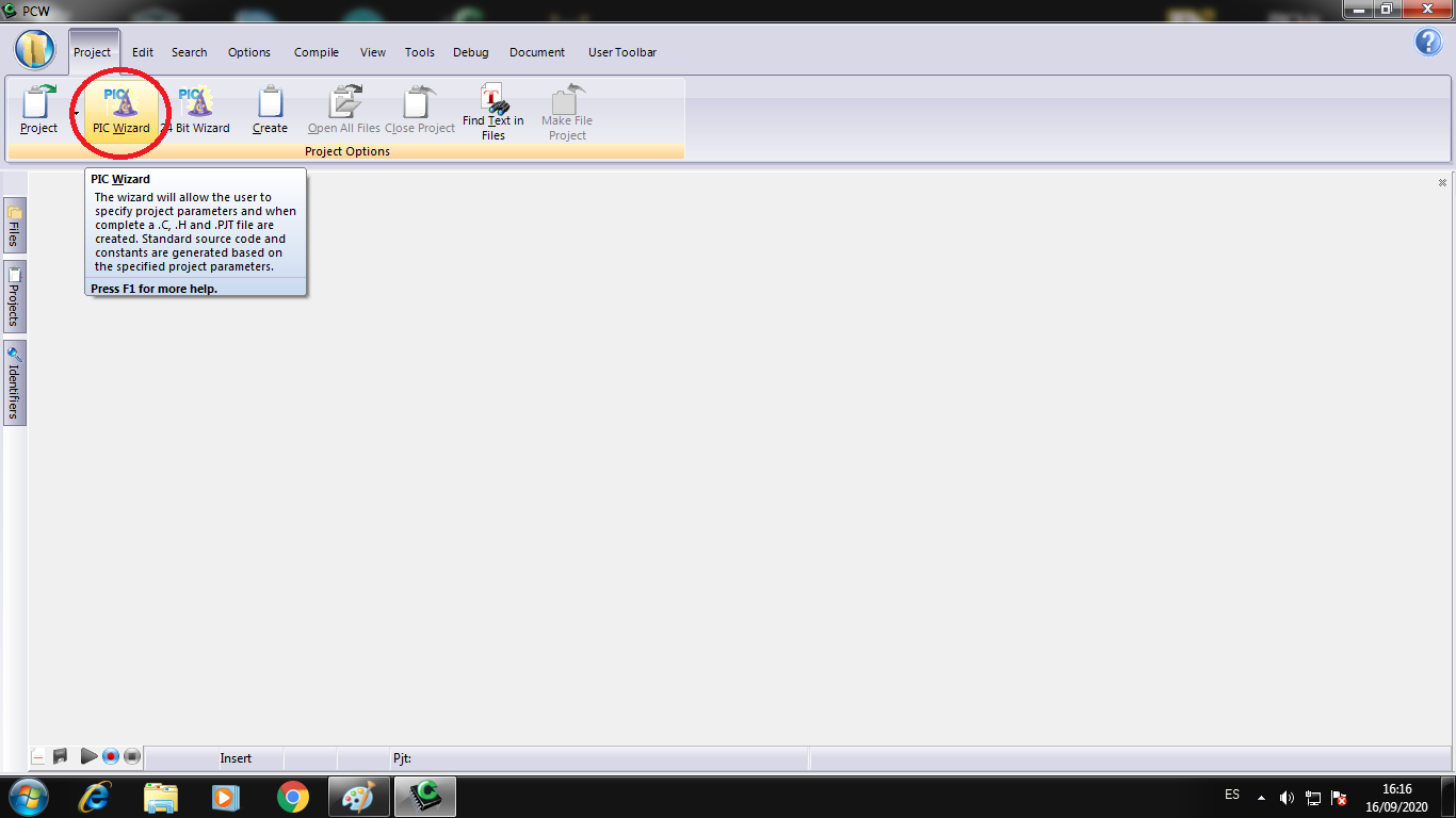
Execute the CCS C Software:
In the menu choose Project->Pic Wizard to create a project:
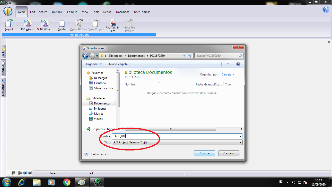
Choose the name of the project and save in a folder:
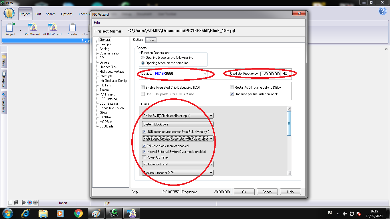
Choose the microcontroller PIC18F2550, the word frecuency to 20MHz and configuration the word bits:
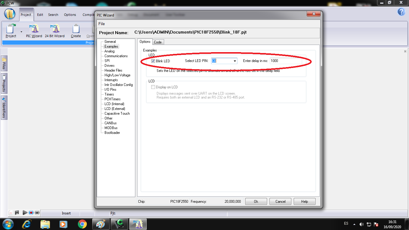
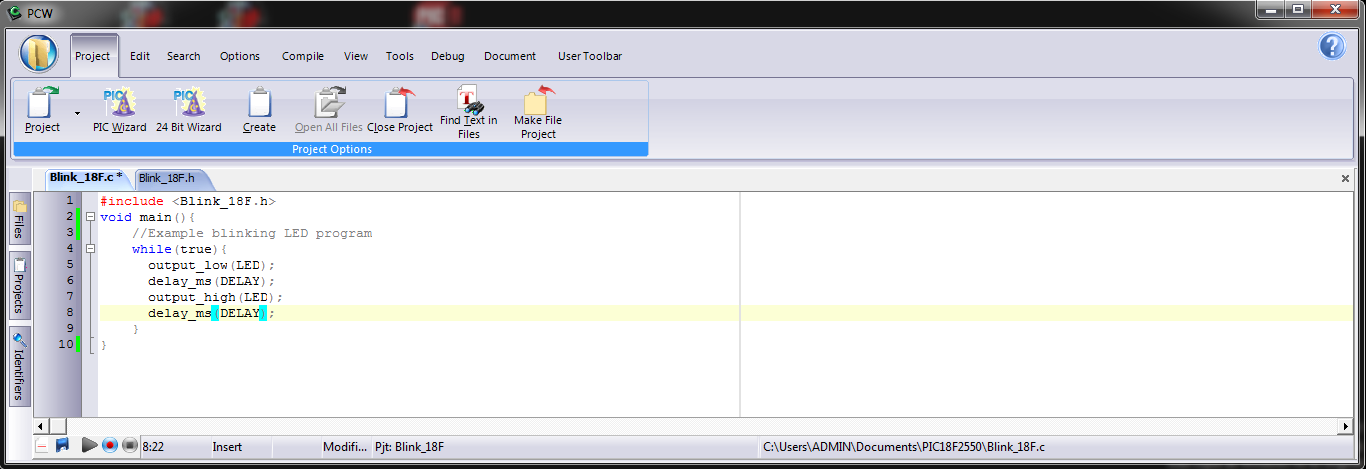
Choose the Blink LED template on the C0 pin of PIC with 1000 miliseconds to work:
The program is ready to load the board:
In the menu choose Compile -> Build to compile and build the HEX file:
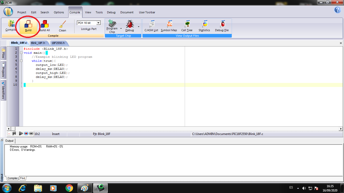
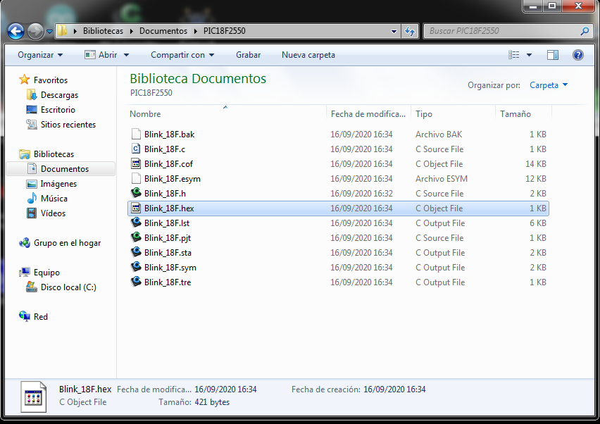
When the compiler build the project, it create other files as COF and HEX files, we need the HEX files to load the microcontroller PIC:
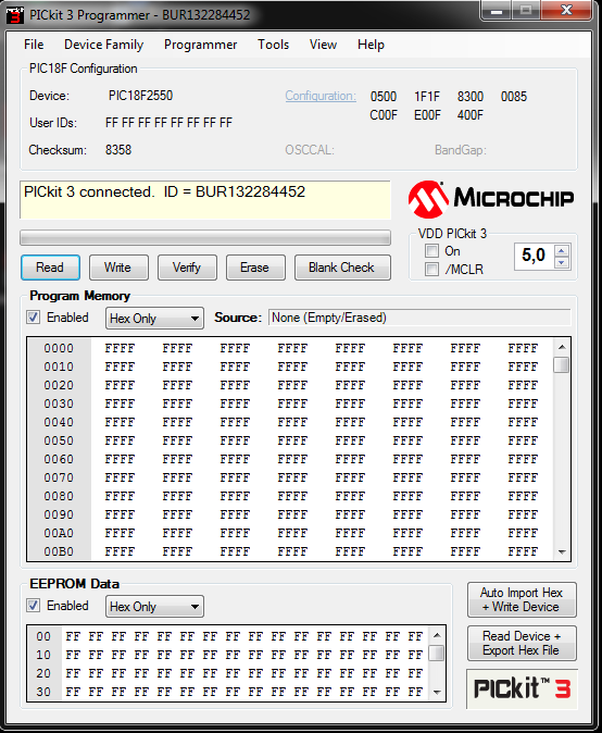
I connect the PICKit 3 programmer from Microchip and install the PICKit 3 software to program the PIC18F2550:
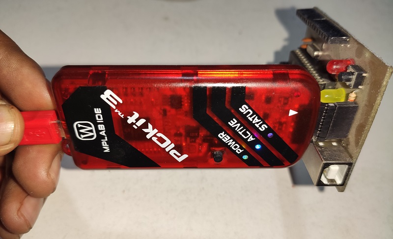
The software recognize the PIC and it is ready to work:
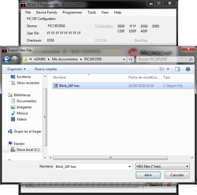
I import the Hex file to software, I went the address file:
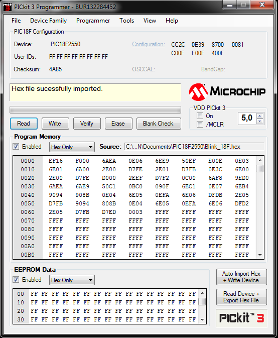
The Hexadecimal data is load to PICKit 3 software:
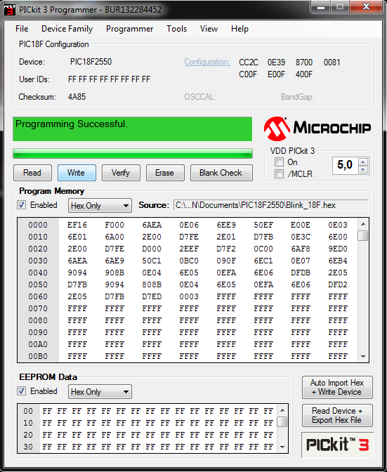
I click to Write button to load the HEX data to PIC18F2550:
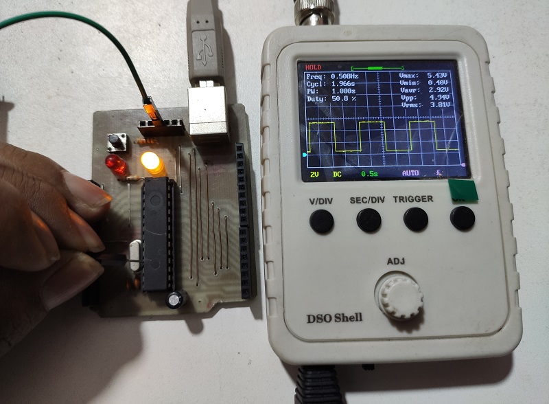
Now, We can see the board working with the blinking Led:
We can see the board with the signal in the Oscilloscope:
3. Testing the ESP8266 in C++
The ESP8266 is a SOC chip from ESPRESSIF Company, in the page https://www.espressif.com/en/products/socs/esp8266 we can learn more about it.
I will program it with Arduino IDE and I will configurate to do it.
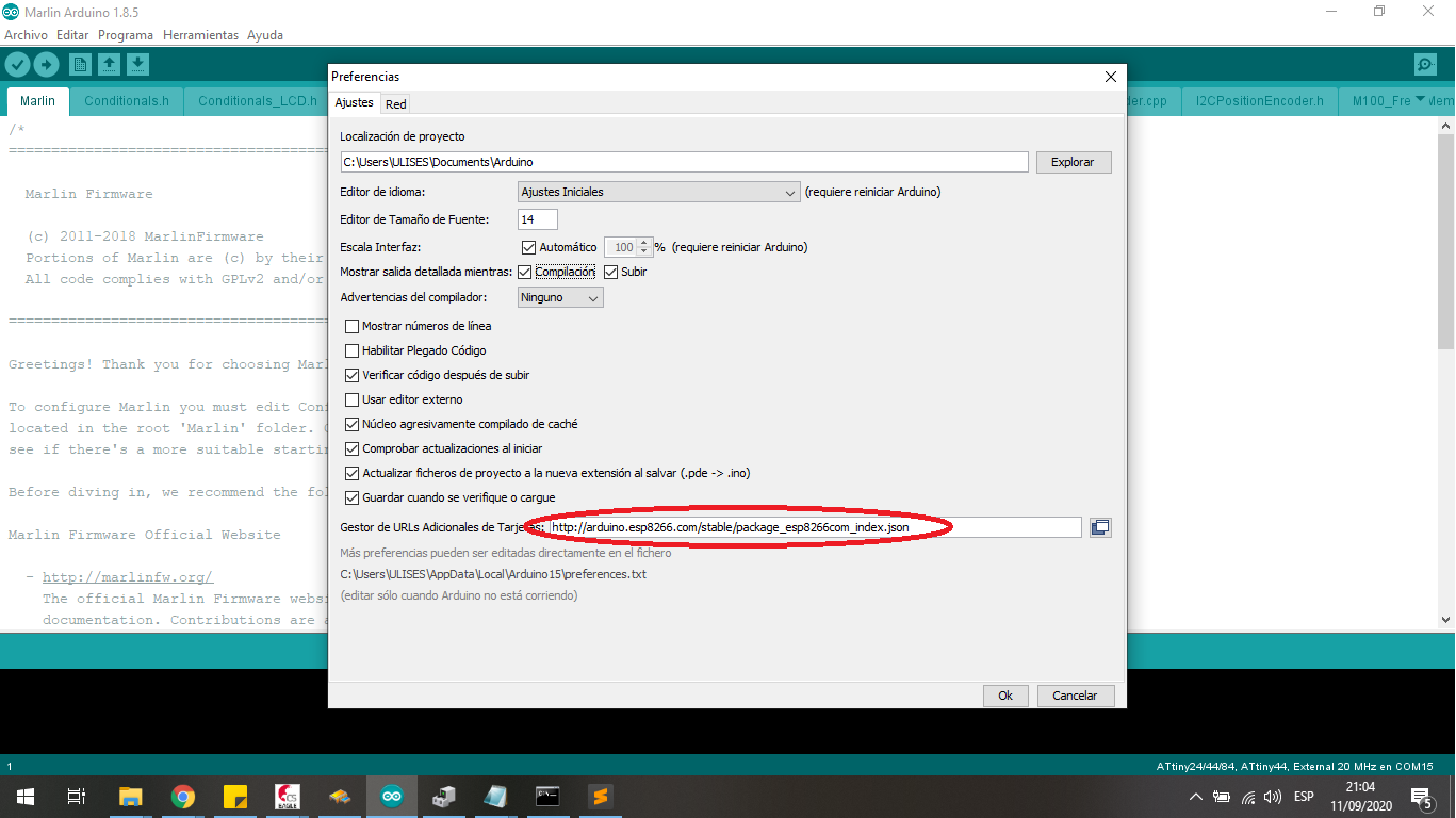
First I download the libraries to Arduino IDE from the Development page, it is http://arduino.esp8266.com/stable/package_esp8266com_index.json
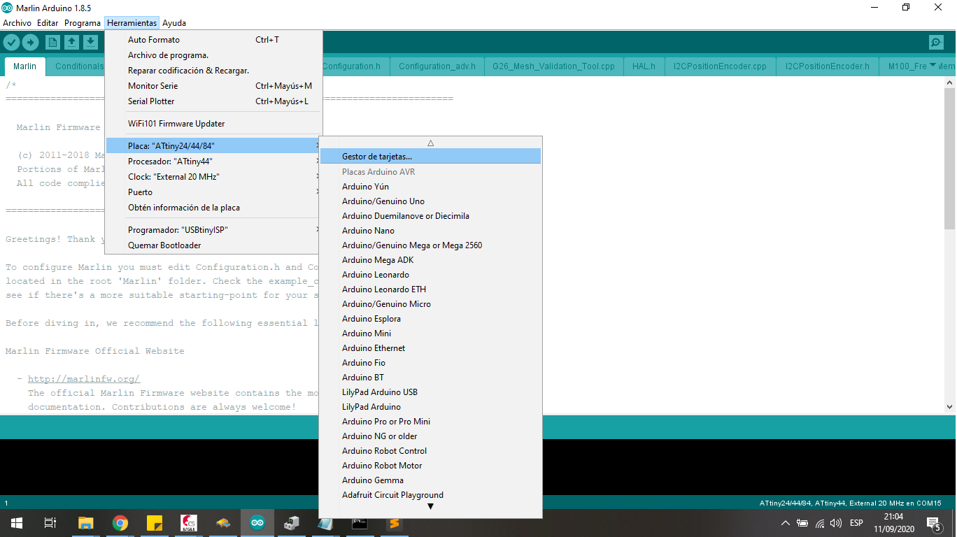
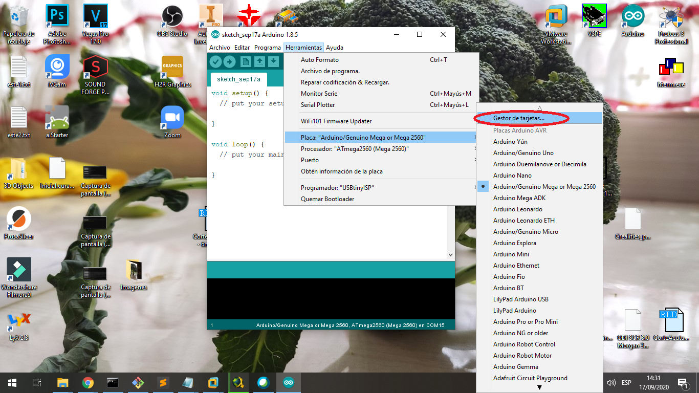
In the menu choose Tools -> Board -> Manager Board to load the profile and compiler ESP8266 board:
In the search area to write esp8266 to filter the files:
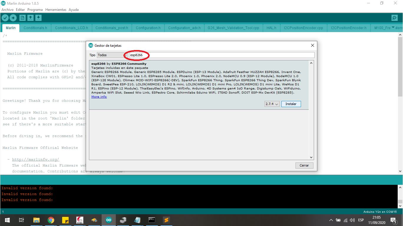
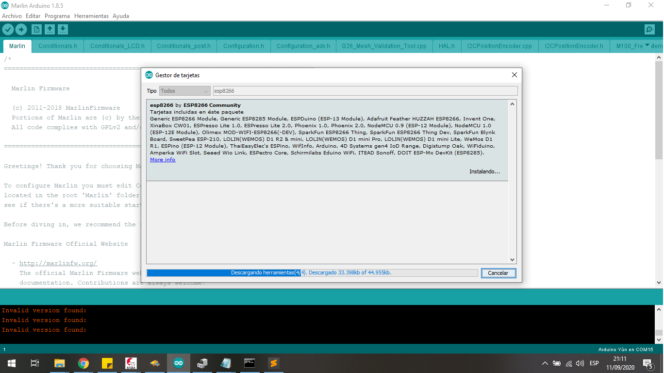
I choose the esp8266 by ESP8266 Community and install this tools to work with the Lolin Boord:
I choose the board to work with the blink program:
Open the blink example and change the ledblinking variable to 2 pin to Lolin Board:
To load the compilled file I press the RESET Button:
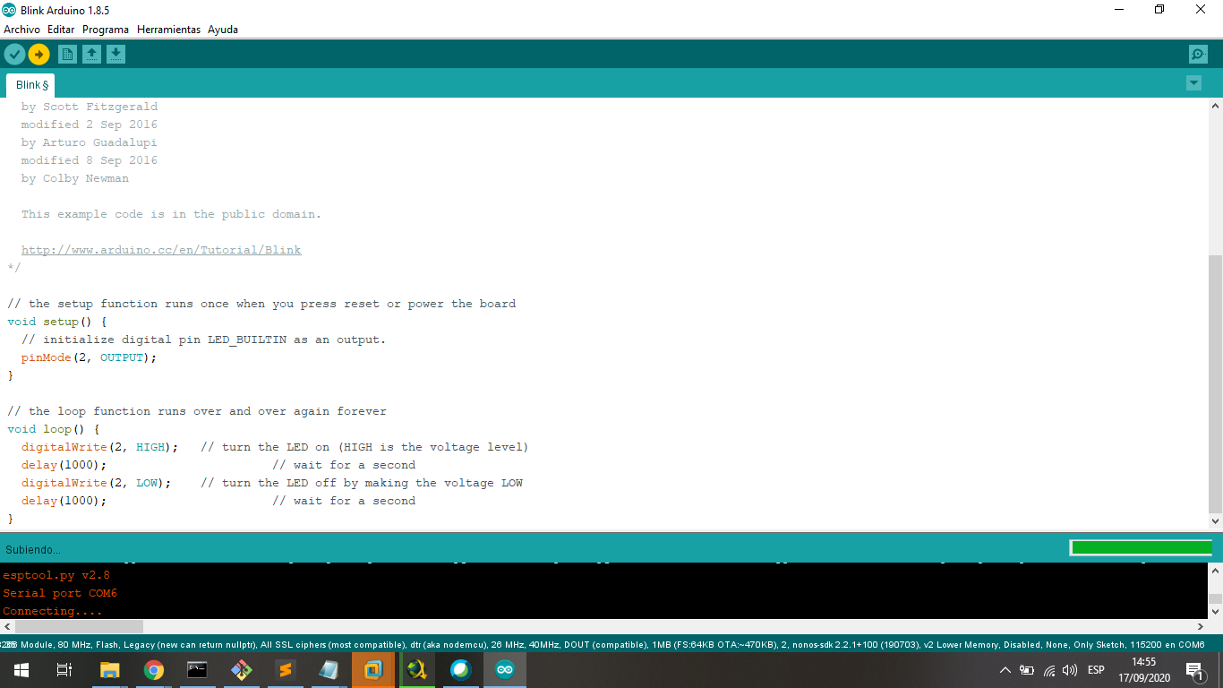
And finally the program is loaded:
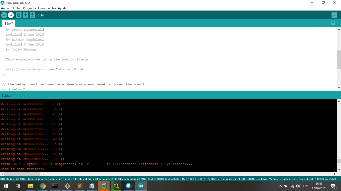
We can see the board with the signal in the Oscilloscope:
4. Testing the ESP32 in C++
The ESP32 is a SOC chip from ESPRESSIF Company, in the page https://www.espressif.com/en/products/socs/esp32 we can learn more about it.
I will program it with Arduino IDE and I will configurate to do it.
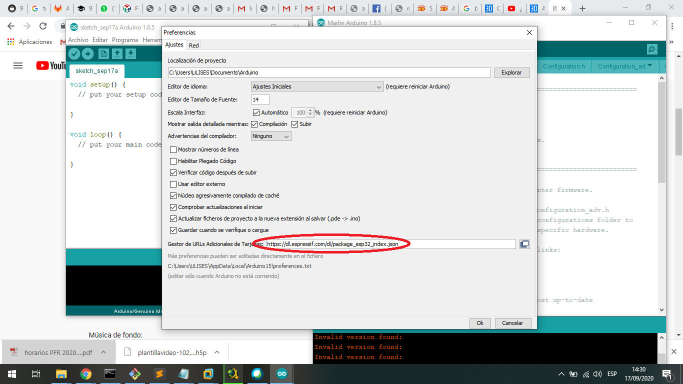
First I download the libraries to Arduino IDE from the Development page, it is https://dl.espressif.com/dl/package_esp32_index.json, I copy and paste in Preferences in Arduino Menu:
In the menu choose Tools -> Board -> Manager Board to load the profile and compiler ESP8266 board:
In the search area to write esp32 to filter the files:
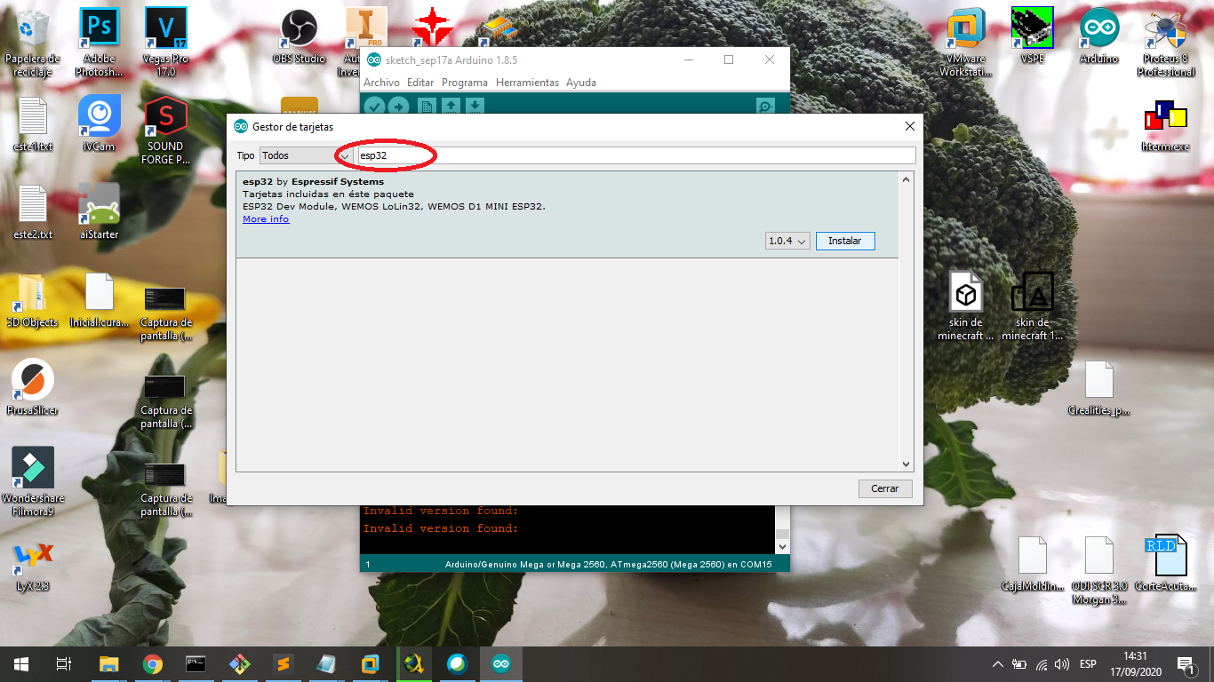
I choose the esp32 by Espressif Systems and install this tools to work with the boord:
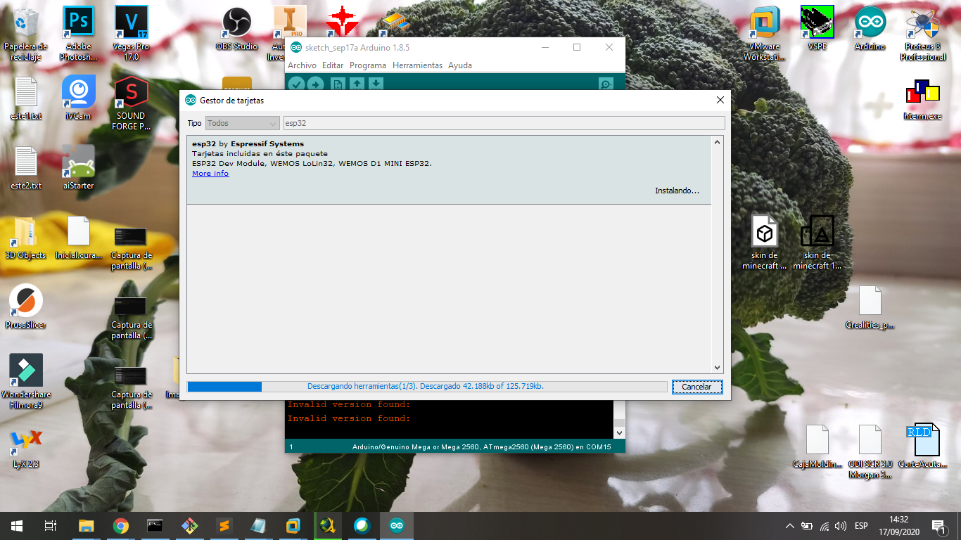
Then the files were installed:
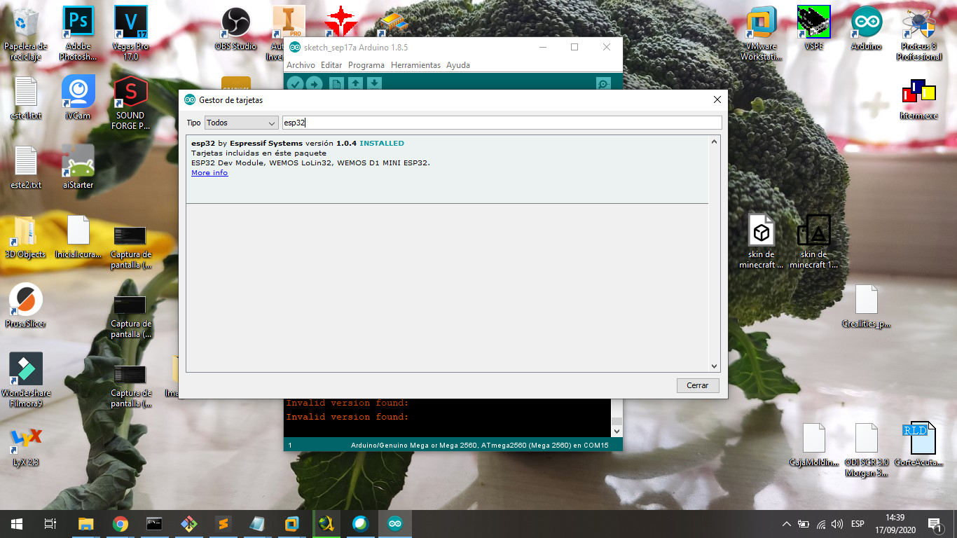
I choose the board to work with the blink program:
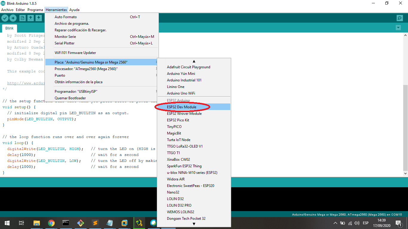
Open the blink example and change the ledblinking variable to 2 pin to board:
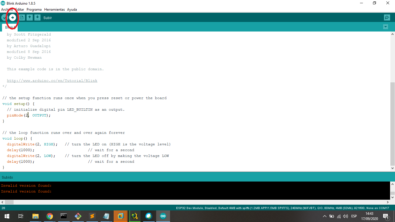
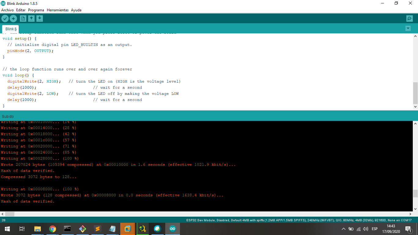
I load the program to board and it is ready to work and test:
We can see the board with the signal in the Oscilloscope:
5. Testing the Attiny44A in C++
The programming and loading process we can see in the individual assignment.
We can see the board with the signal in the Oscilloscope:
Designed Files
| Description | Files |
|---|---|
| Ultrasonic Sensor Project | Ultrasonic.ino |
| Cpp File from PIC18F2550 | Blink_18F.c |
| Header File from PIC18F2550 | Blink_18F.h |
| ASM File | Blink_44.asm |
| Arduino File | Blink_44.ino |