18. Mechanical Design / Machine Design
Group Assignment
- Design a machine that includes mechanism + actuation + automation
- Build the mechanical parts and operate it manually
- Actuate and automate your machine
- Document the group project and your individual contribution
Group Assignment
This week I worked on defining, designing and manufacturing a new machine related to and based on the machine proposed in my final project.
I will work on a conventional filament 3D printer, for this purpose we will divide the work into the following items:
- XYZ Movements Structure
- Design and Manufacture of Extruder Structure
- Software Configuration
- 3D Printing Tests
XYZ Movements Structure
For the structure and to achieve the movements of X, Y and Z we will use the structure that was worked on in my final project, in the part called with the same name.
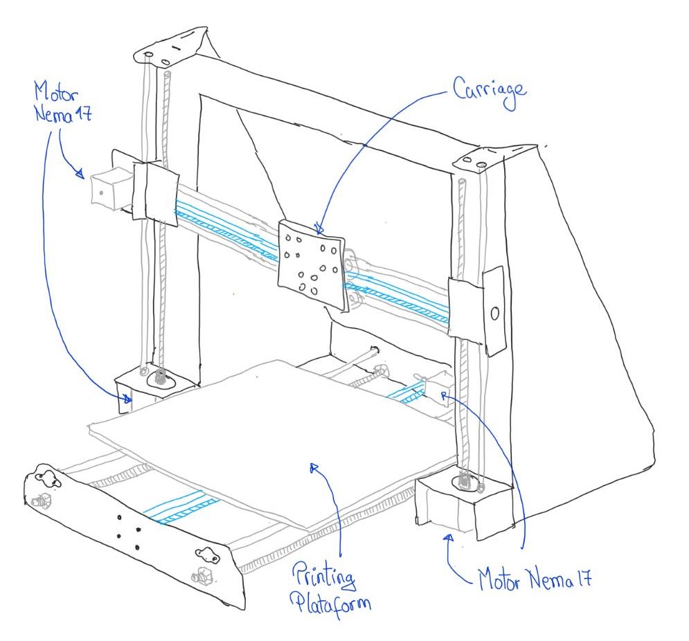
This information can be found in the XYZ Structure Section from Final Project
In the mentioned item we can see from the sketch to finish with the structure of X, Y and Z movements finished:
Design and manufacture of Extruder Structure
To work with the extruder we will have the following items:
- Inspiration
- Sketch
- CAD design
- Fabrication process
- Assembly Process.
- Assembly Process to the Structure of X, Y and Z Movements
Inspiration
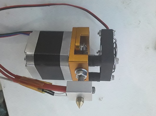
To carry out the hot extrusion process in filament we will use the MK8 extruder model, which we can see in the image:
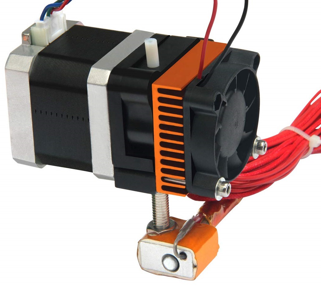
Then we must work on a structure that supports the MK8 extruder
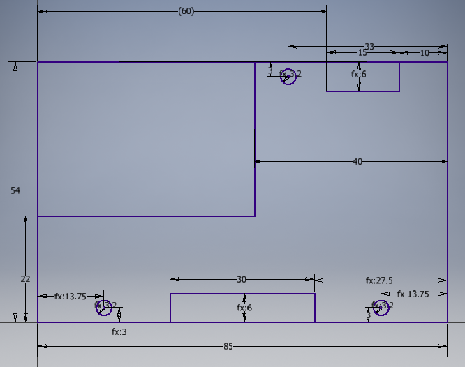
Sketch
The idea is to support the extruder in sheets to the contour of the MK8, so that the entire structure would be made with laser cutting.
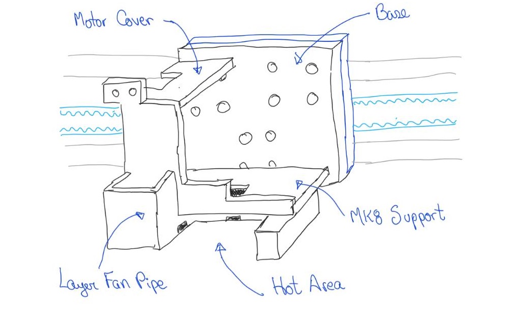
This would be the initial sketch of the support for the MK8 extruder.
CAD design
For the design, Autodesk Inventor software was used and proceeded to design:
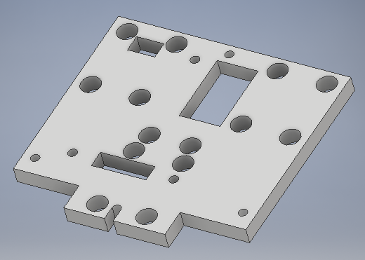
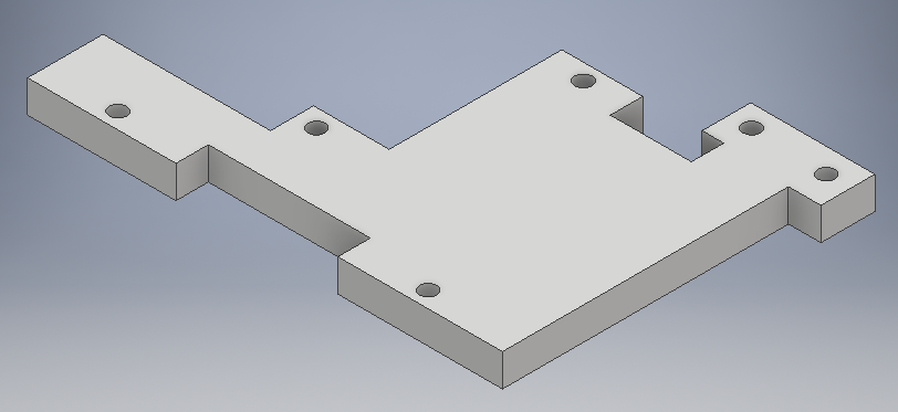
Designing the base:
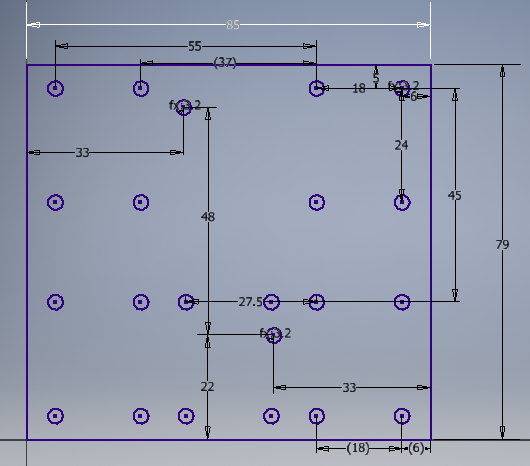
The base design is finished:
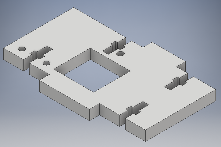
Designing the support for the MK8:
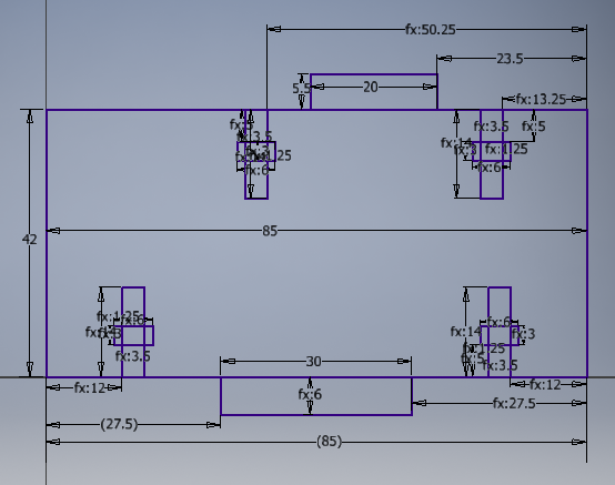
The support design for the MK8 is finished:
Designing the cover for the Nema 17 motor:
The cover design for the Nema 17 motor is finished:
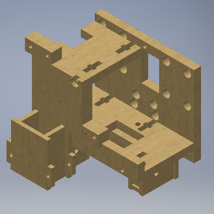
Presentation of the finished extruder seen in isometric
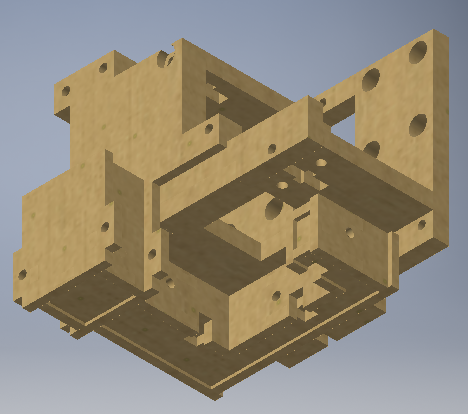
Presentation view of the extruder from below
Fabrication process
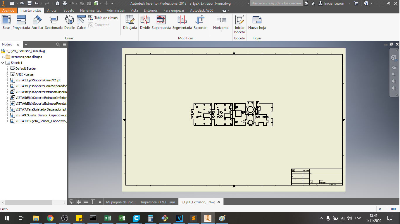
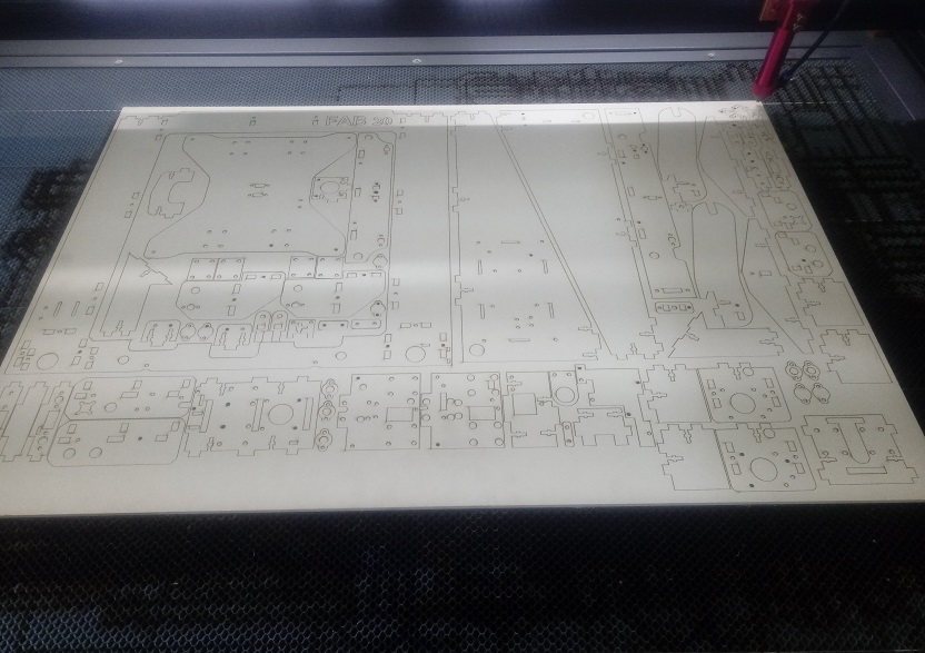
The manufacturing was carried out with laser cut in 6mm and 3mm thick MDF.
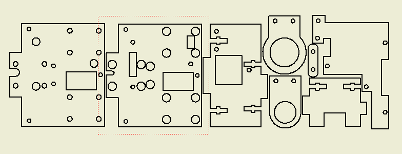
For this purpose, the 3D files were converted to a 2D file with the profiles of the designs in Autodesk Inventor.
We can see the complete pieces:
The process that was used is the same as that used in the processes of week 4.
Assembly Process.
Here we have the MK8 extruder to use it in the extruder of the 3D printer:
We have all the parts that we require for the assembly of the extruder:
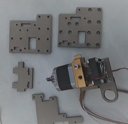
We start with the extruder support:
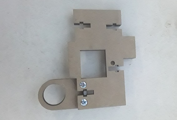
We hold the support in the extruder itself:
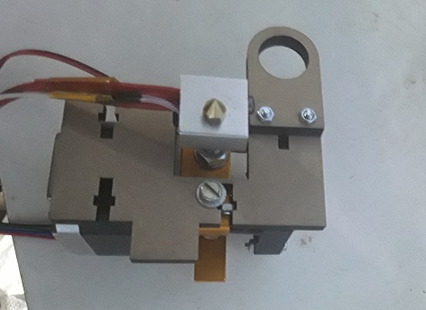
We place the base and the front cover, using 1/8 inch bolts:
We fasten the back base to attach it to the extruder carriage
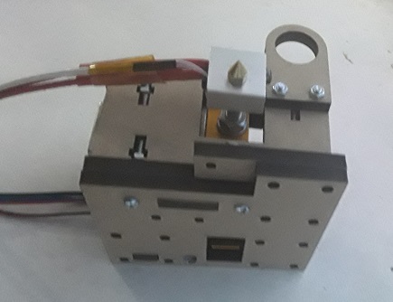
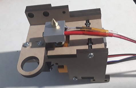
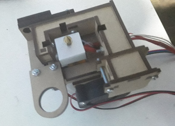
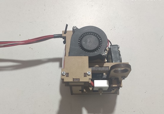
We can see the fully assembled bottom extruder:
Assembly Process to the Structure of X, Y and Z Movements
We begin in assembly with the structure of X, Y and Z movements.
First we have the Extruder ready to assemble it:
We join the extruder to the base of the displacement carriage, as shown in the image, for which we have 3 fastening bolts.
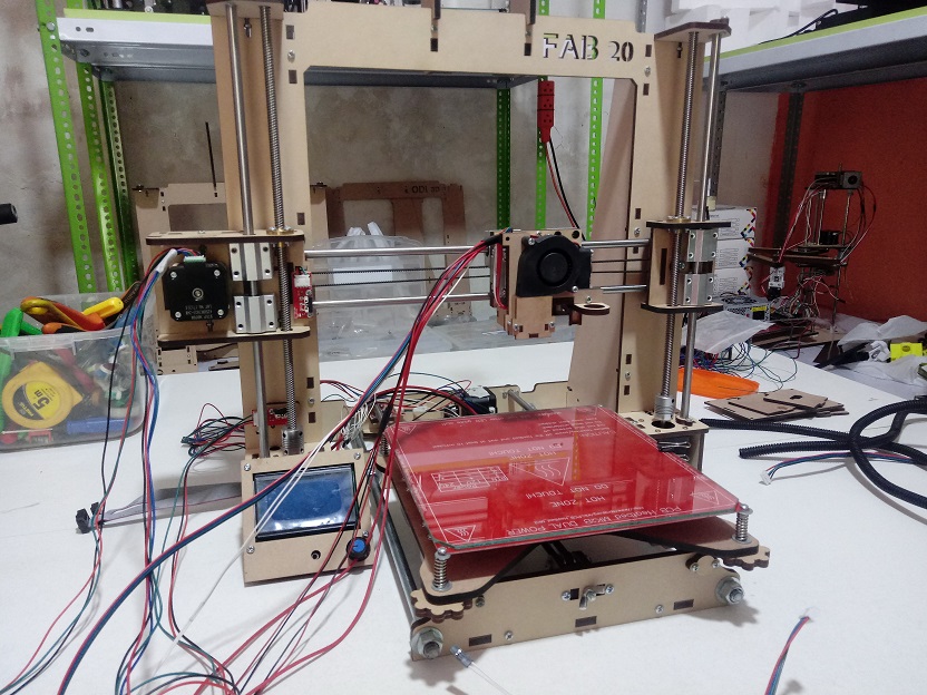
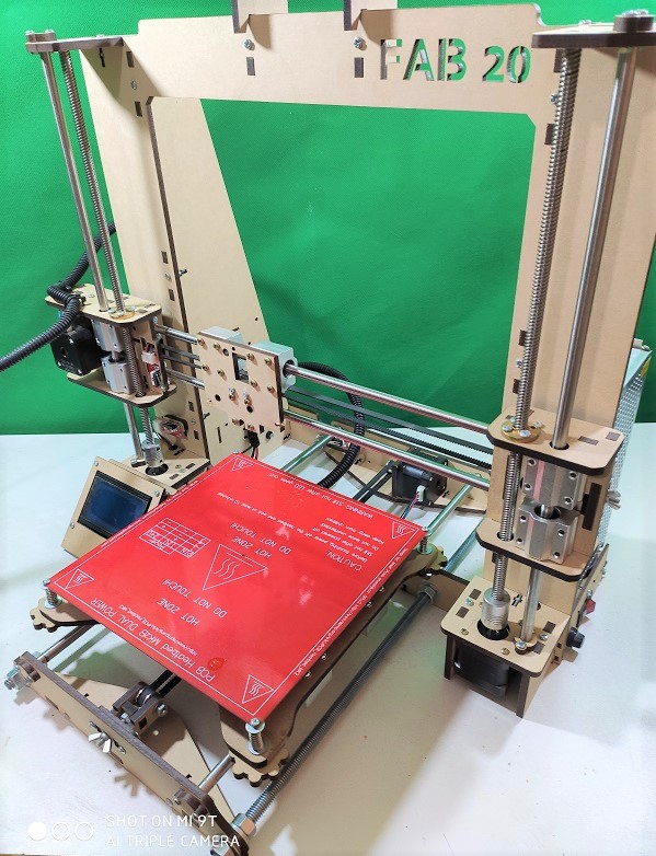
Then we have the printer with the extruder attached to the moving carriage
We can a sample of how it looks in the following video:
Electronic
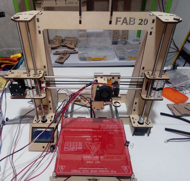
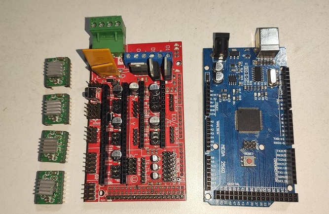
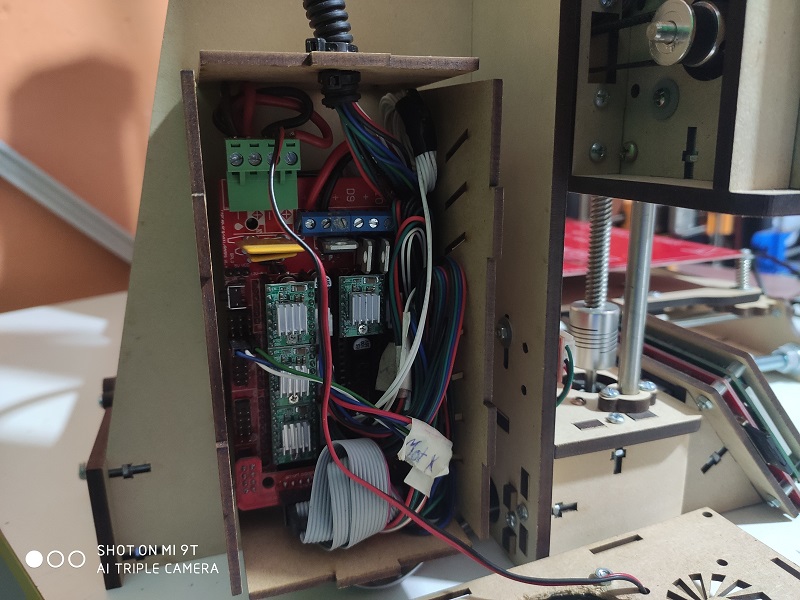
For the electronics we use the Arduino Mega + Ramps 1.4 board, which is used in most of the 3D printers of the REPRAP Community, on which we rely to create the FAB 20.
The connection diagram is based on the RAMPS 1.4 documentation from its official website RAMPS 1.4
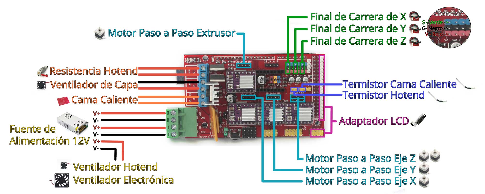
This would be the electronics to use:
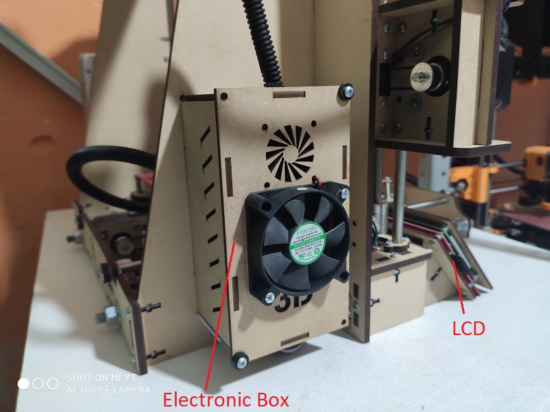
This is the electronics assembled and placed in its box
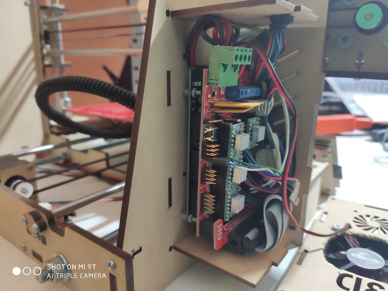
Here we have another view, the connection is the same recommended by the REPRAP community
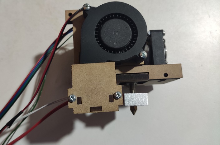
This would be the finished extruder of the previous stages
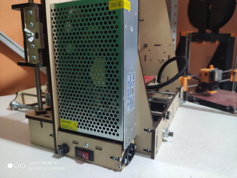
This would be the power supply with a 220VAC connection, ON / OFF switch and 2A fuse
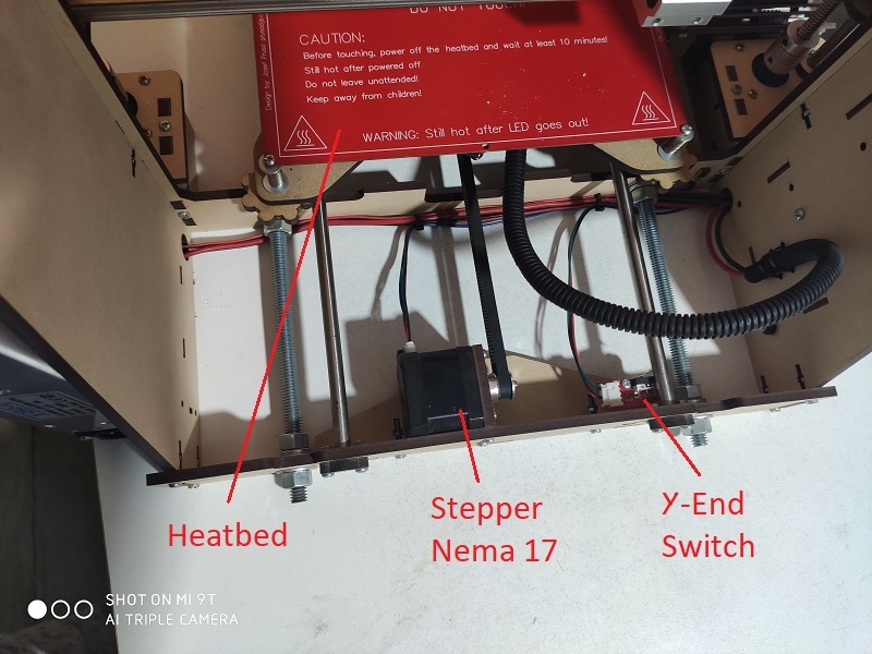
This would be the electronics at the base of the printer, stepper motor, Y axis limit switch
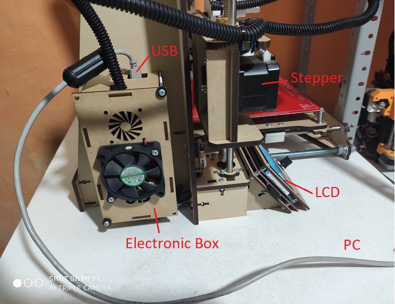
In this image we can see the LCD Panatalle and the electronics box
In this image we can connect the 3D printer to the computer, through a USB cable
Software Configuration
To work with the software configuration we will have the following items:
- Marlin Firmware Configuration
- Calibration with Pronterface software
- Ultimaker Cura Software Configuration.
Marlin Firmware Configuration
We can download the marlin firmware for 3D printer from the following page Official Marlin Page
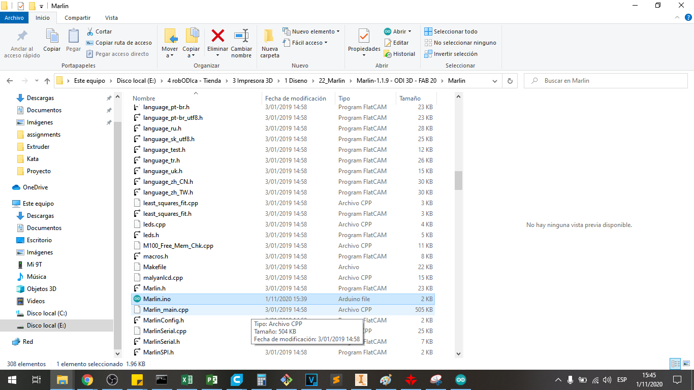
Let’s choose versions 1.1.9, because it is a version for 8 bit microcontrollers since we will use the Atmega2560 as microcontroller for the 3D printer
We enter the downloaded folder and locate the file marlin.ino:
We choose from all the tabs, the file tab Configuration.h
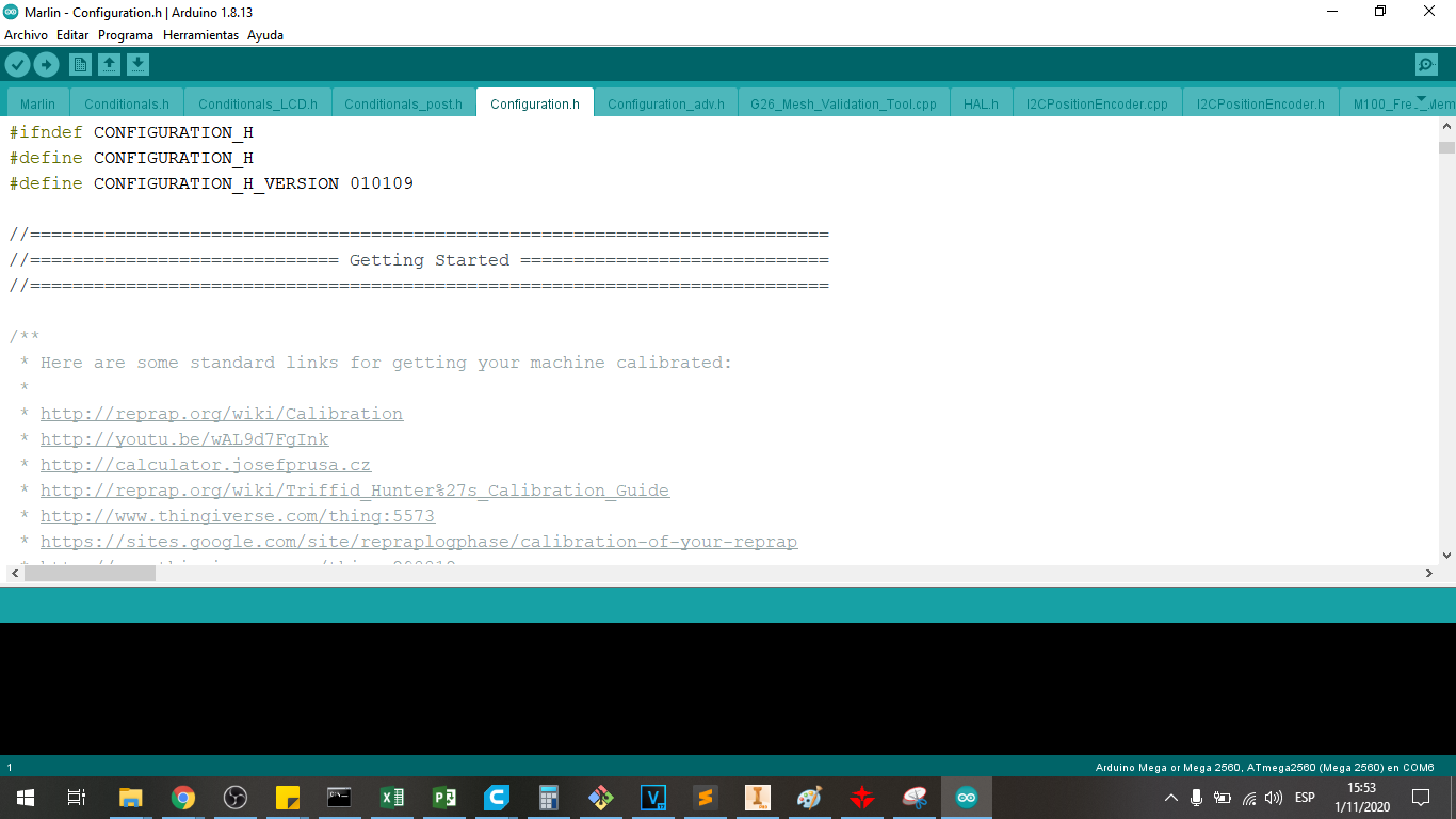
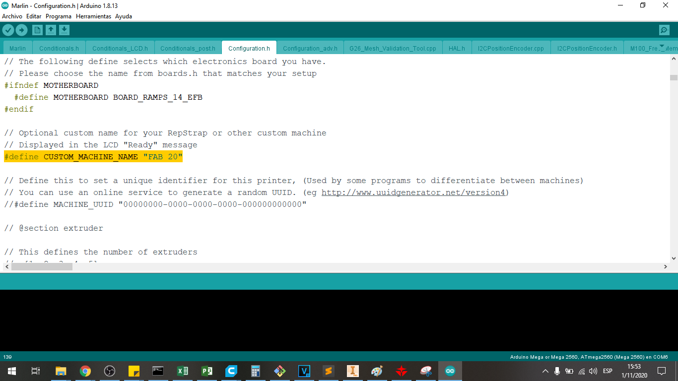
We place the name of the printer to be programmed, which in our case we will name it as FAB 20, this can be done in the following line:
#define CUSTOM_MACHINE_NAME "FAB 20"
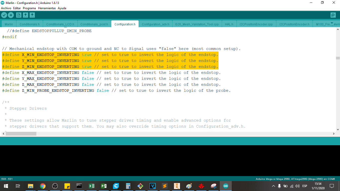
We must define the direction of operation of the limit switches for the X, Y and Z axes, this can be done in the following line:
    #define X_MIN_ENDSTOP_INVERTING true // set to true to invert the logic of the endstop.
    #define Y_MIN_ENDSTOP_INVERTING true // set to true to invert the logic of the endstop.
    #define Z_MIN_ENDSTOP_INVERTING true // set to true to invert the logic of the endstop.
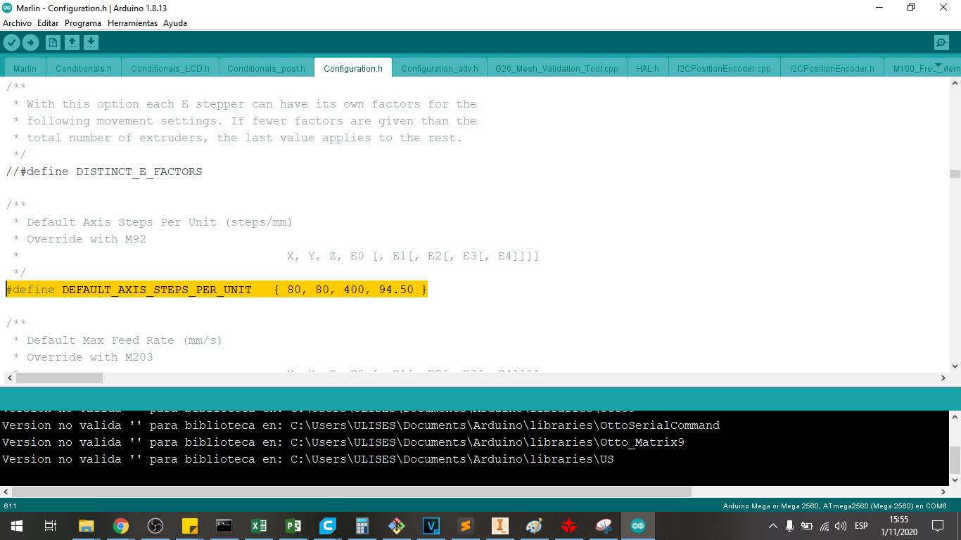
We must define the steps per unit of advance, that is, the steps per millimeter of advance, this can be done in the following line:
#define DEFAULT_AXIS_STEPS_PER_UNIT { 80, 80, 400, 94.50 }
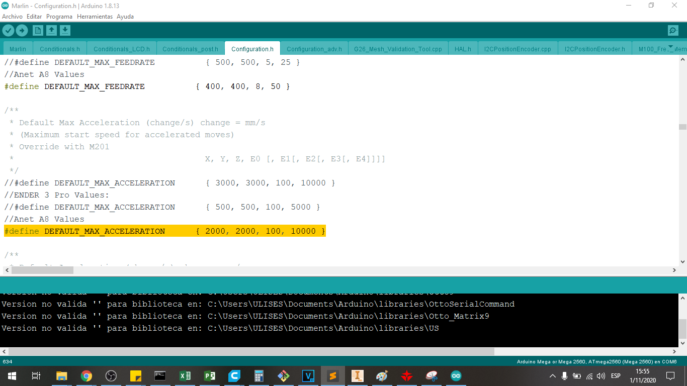
We must define the acceleration of each of the motors to control the starting or braking mode in the movements, this can be done in the following line:
#define DEFAULT_MAX_ACCELERATION { 2000, 2000, 100, 10000 }
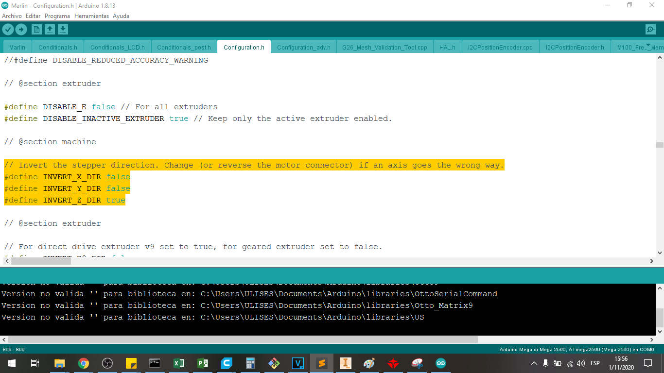
We must define the directions of the motor movements to have the correct advance in X, Y and Z, this can be done in the following line:
    #define INVERT_X_DIR false
    #define INVERT_Y_DIR false
    #define INVERT_Z_DIR true
Invert the stepper direction. Change (or reverse the motor connector) if an axis goes the wrong way.
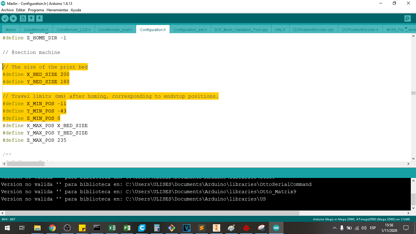
We defining the size of the print bed 200mm in X and 180mm in Y
    #define X_BED_SIZE 200
    #define Y_BED_SIZE 180
The positions of the end of races are not in 0,0,0 of the heatbed, then we need to indicate this offset
It is the travel limits (mm) after homing, corresponding to endstop positions in X. Y and Z axis:
    #define X_MIN_POS -11
    #define Y_MIN_POS -43
    #define Z_MIN_POS 0
Then, we have uploaded this program to the arduino mega for its calibration, we choose the serial port, we choose the arduino mega 2560 and upload it.
Calibration with Pronterface software
We use Pronterface software to configure the printer parameters, we can download it from the following Official Pronterface Page
Let’s choose Printrun-win-18Nov2017, because it is a newest version of the software.
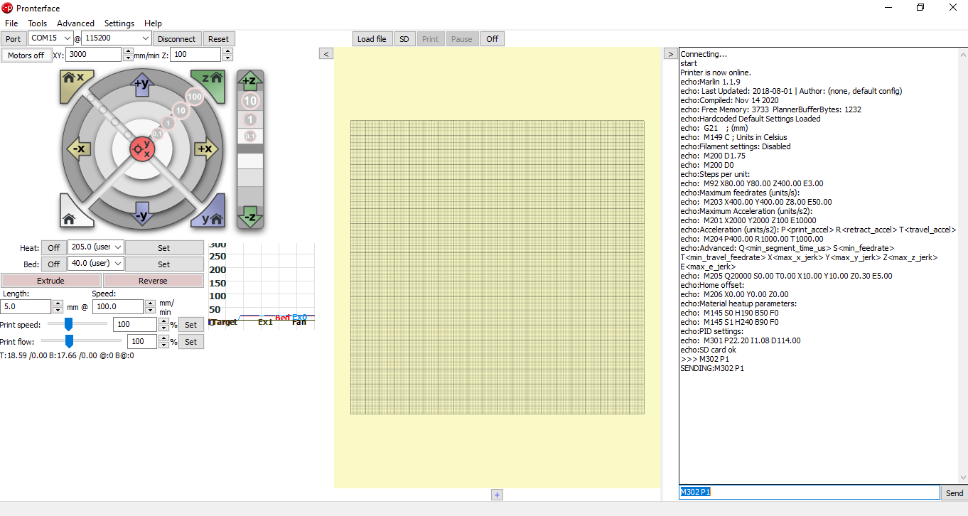
We open the program:
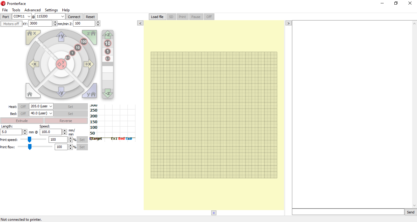
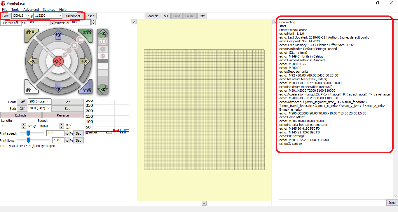
We choose the serial port, in my case it is COM15, we choose the communication speed of 115200 baud, and we press CONNECT
Then a printer connection message is displayed:
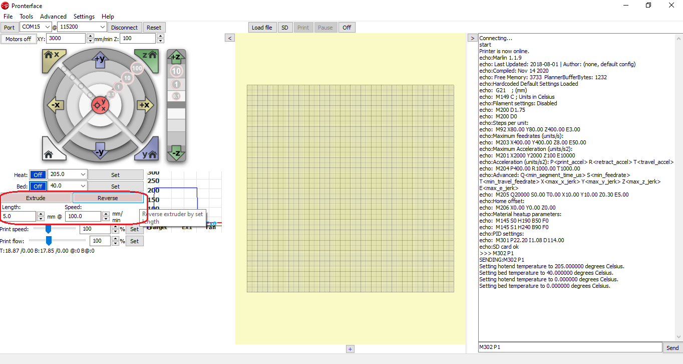
To carry out the configuration, we send the command of M302 P1, to be able to make cold movement of the 3D printer, so that we can calibrate the step of the extruder.
Then we can already extrude cold to calibrate the steps per millimeter for the extruder, in our case it would be 94.50, which was placed in the marlin instruction:
#define DEFAULT_AXIS_STEPS_PER_UNIT { 80, 80, 400, 94.50 }
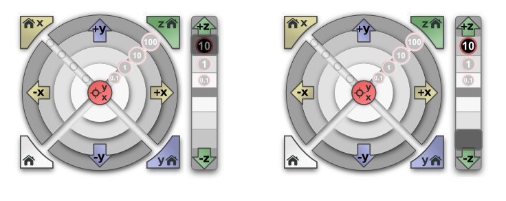
We can calibrate the steps per millimeter using the commands to test the movement in X, succeeding in verifying that this value is 80:
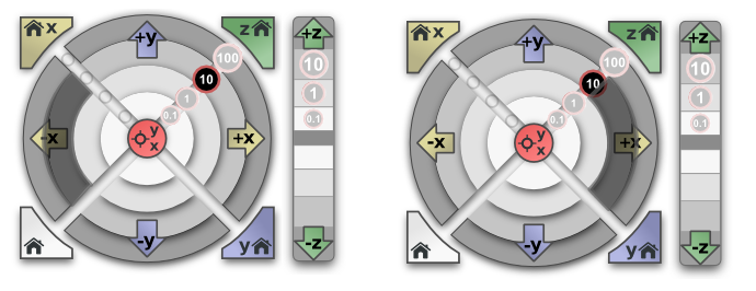
We can calibrate the steps per millimeter using the commands to test the movement in Y, succeeding in verifying that this value is 80:
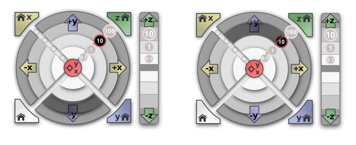
We can calibrate the steps per millimeter using the commands to test the movement in X, succeeding in verifying that this value is 400:
#define DEFAULT_AXIS_STEPS_PER_UNIT { 80, 80, 400, 94.50 }
Said data placed in the marlin instruction:
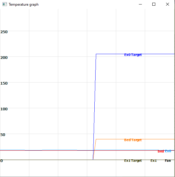
Finally we can calibrate and check the operation of the heaters and temperature sensors for the extruder and the heatbed.
Ultimaker Cura Software Configuration.
The slicer is the program that converts the STL file into a GCODE command that the 3D printer executes to create the 3D object.
We use Ultimaker Cura software to slice the designed file in 3D CAD software, we can download it from the following Official Ultimakes Page
Let’s choose the newest version of the software.
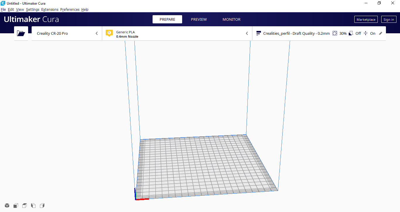
We open the program:
This is the program interface to slice the STL files:
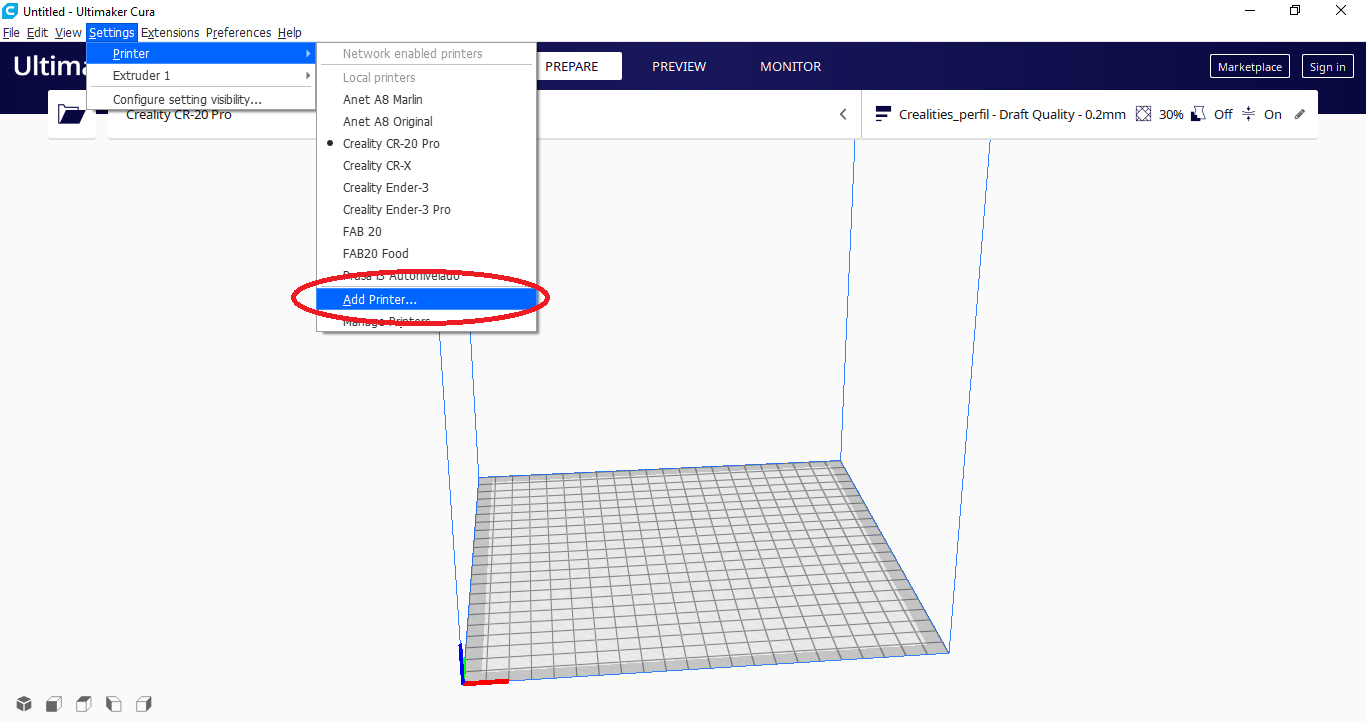
To define a new printer and configure it for the FAB 20, choose Settings > Printers > Add Printers
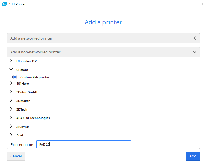
Let’s choose a generic printer, type FFF (Fused Filament Fabrication), and name it as FAB 20
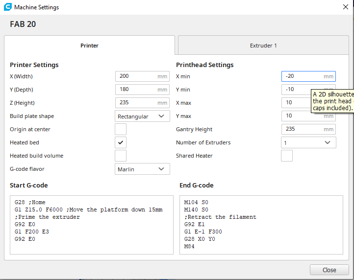
We configure the following parameters referred to the 3D printer FAB 20:
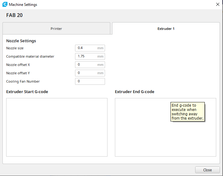
These are the strusor data for the FAB 20:
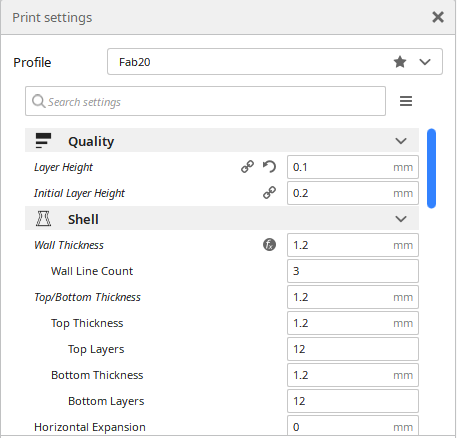
ow we will configure the printing parameters
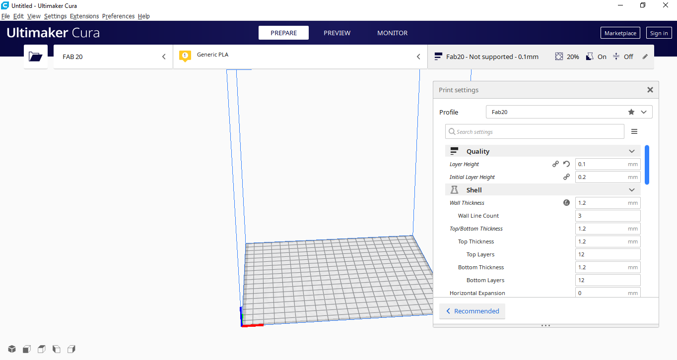
Now we will configure the printing parameters, such as QUALITY and SHELL, with the following values:
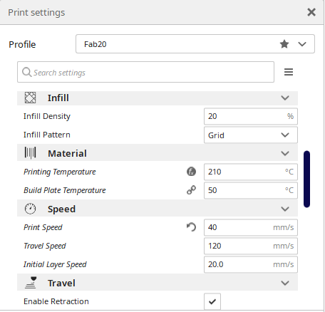
Now we will configure the printing parameters, such as INFILL, MATERIAL and SPEED, with the following values:
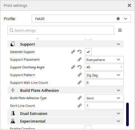
Finally we will configure the printing parameters, such as COOL, SUPPORT and BUILD PLATE ADHESION, with the following values:
3D Printing Tests
Test 1: Test Cubes
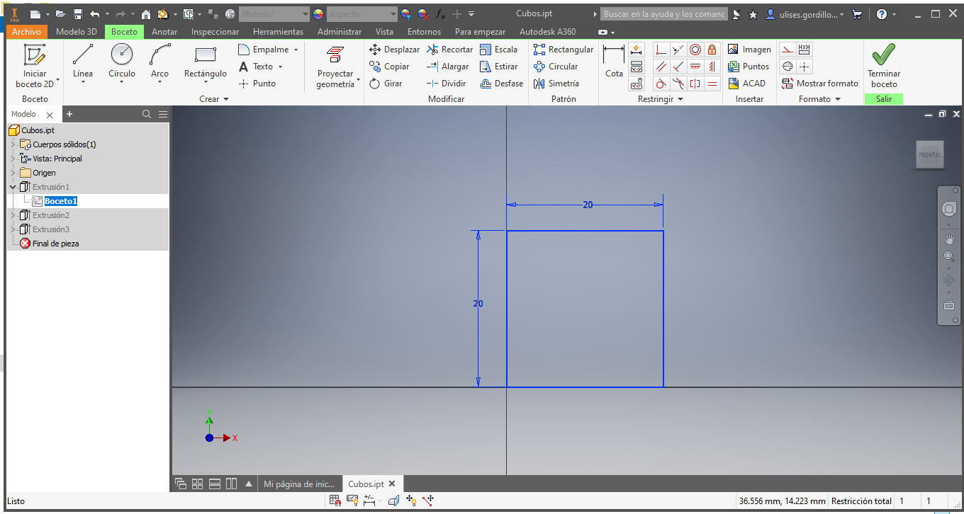
To perform the first test and calibration, we designed 3 cubes with known values in Autodesk Inventor software:
We design a 20 x 20 x 20 mm cube:
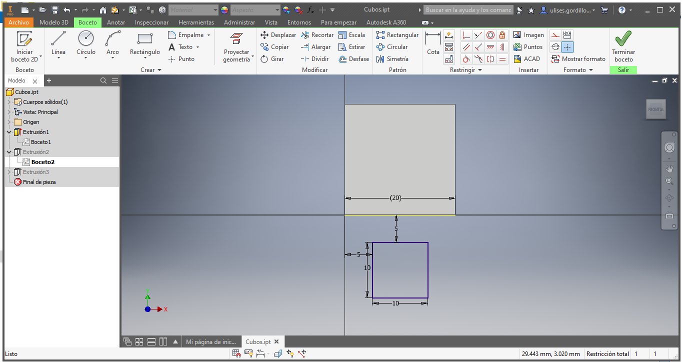
We add a 10 x 10 x 10 mm cube:
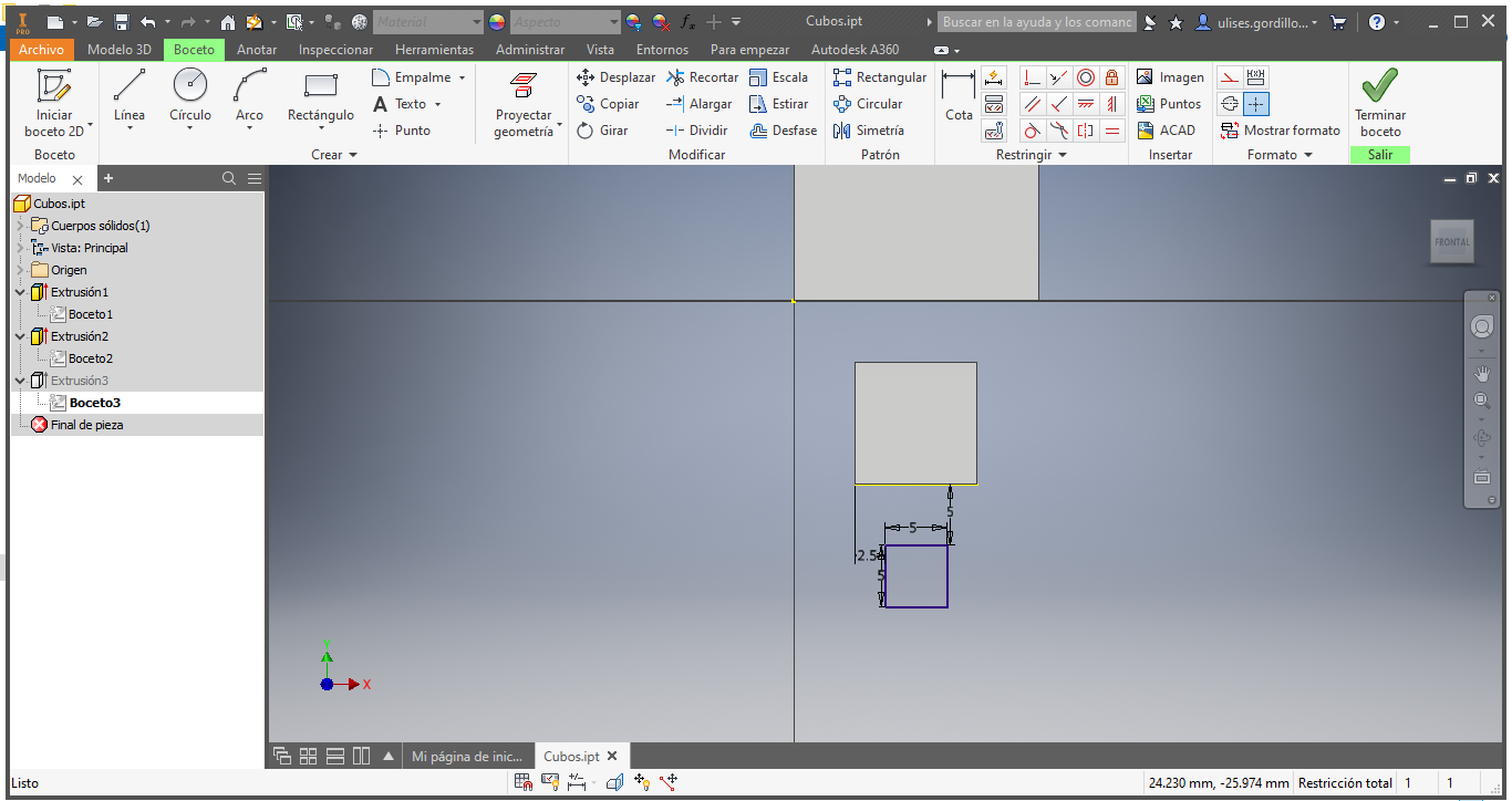
We add a 5 x 5 x 5 mm cube:
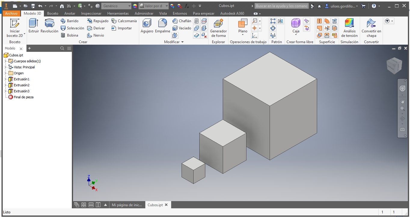
The finished design is the one shown in the following image:
We export the design in an STL file, for printing, we load said file to the Ultimaker Cura software for slice, using the parameters established in previous steps:
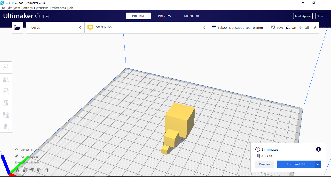
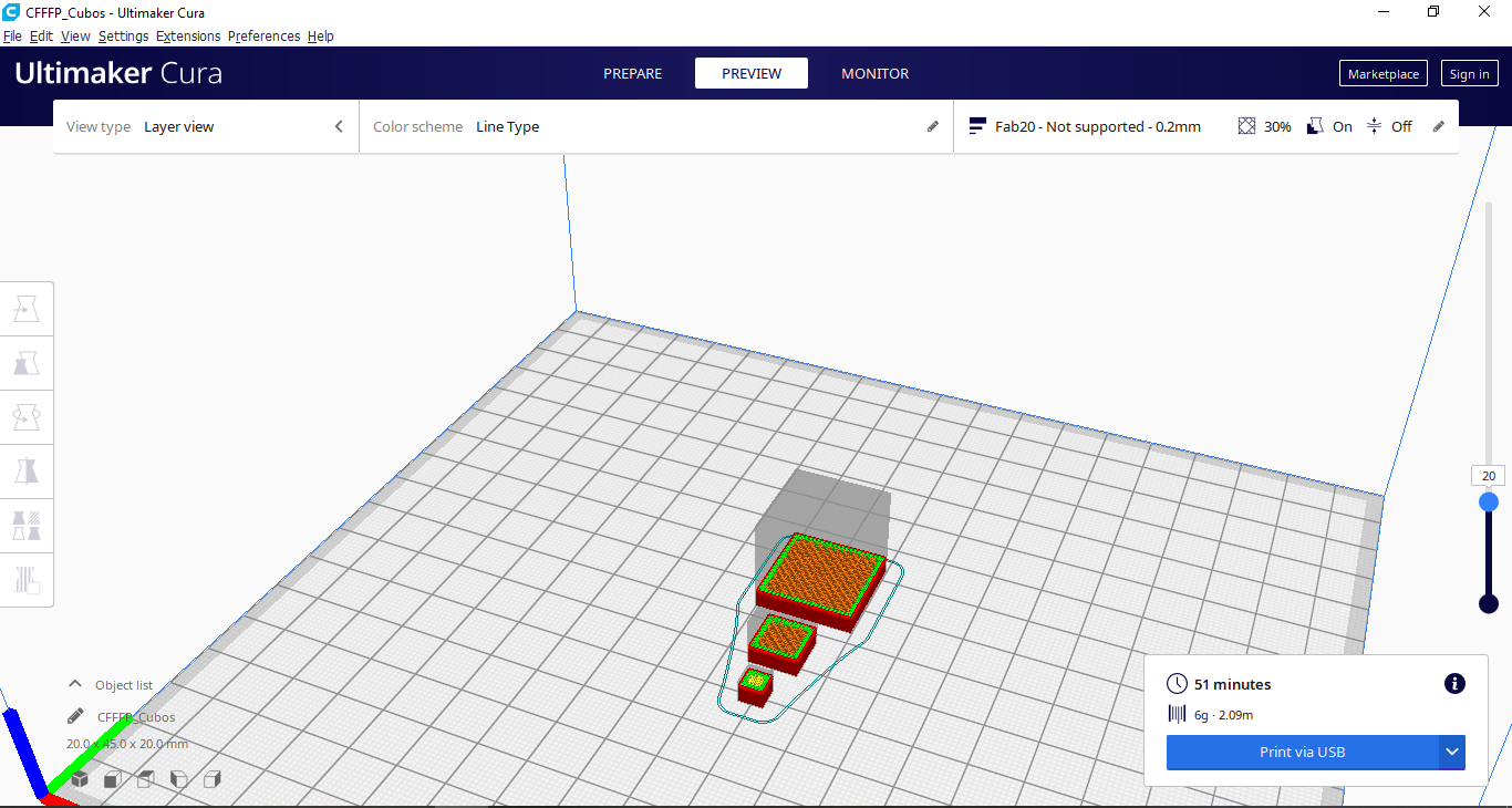
We can see the layers that we will have to print in 3D, we also have a time of 51 minutes of work in said printing:
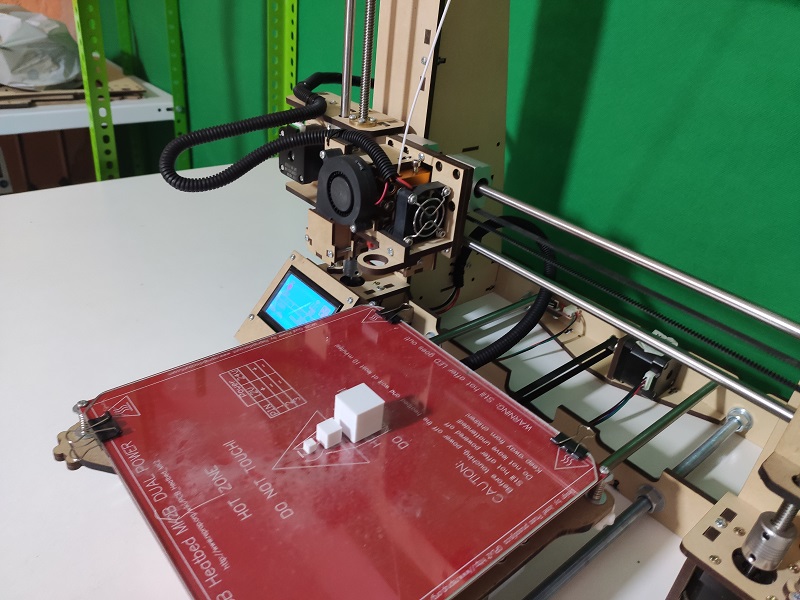
Printing the design
Let’s load the file into the SD memory and run it on the FAB 20 3D printer, to see it we have a video that shows the impression of said design:
After making the 3D printing we have the printed design:
Showing the printed design
We have a video showing the printed design:
We carry out the measurement of the printed cubes of the 3 dimensions and we have the following comparative table:
| Item | Description | Real Dimensions | Printed dimensions |
|---|---|---|---|
| 1 | Cube 20 | 20 mm | 20.1 mm |
| 2 | Cube 10 | 10 mm | 10.0 mm |
| 3 | Cube 5 | 5 mm | 5.2 mm |
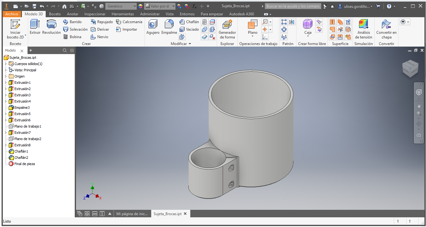
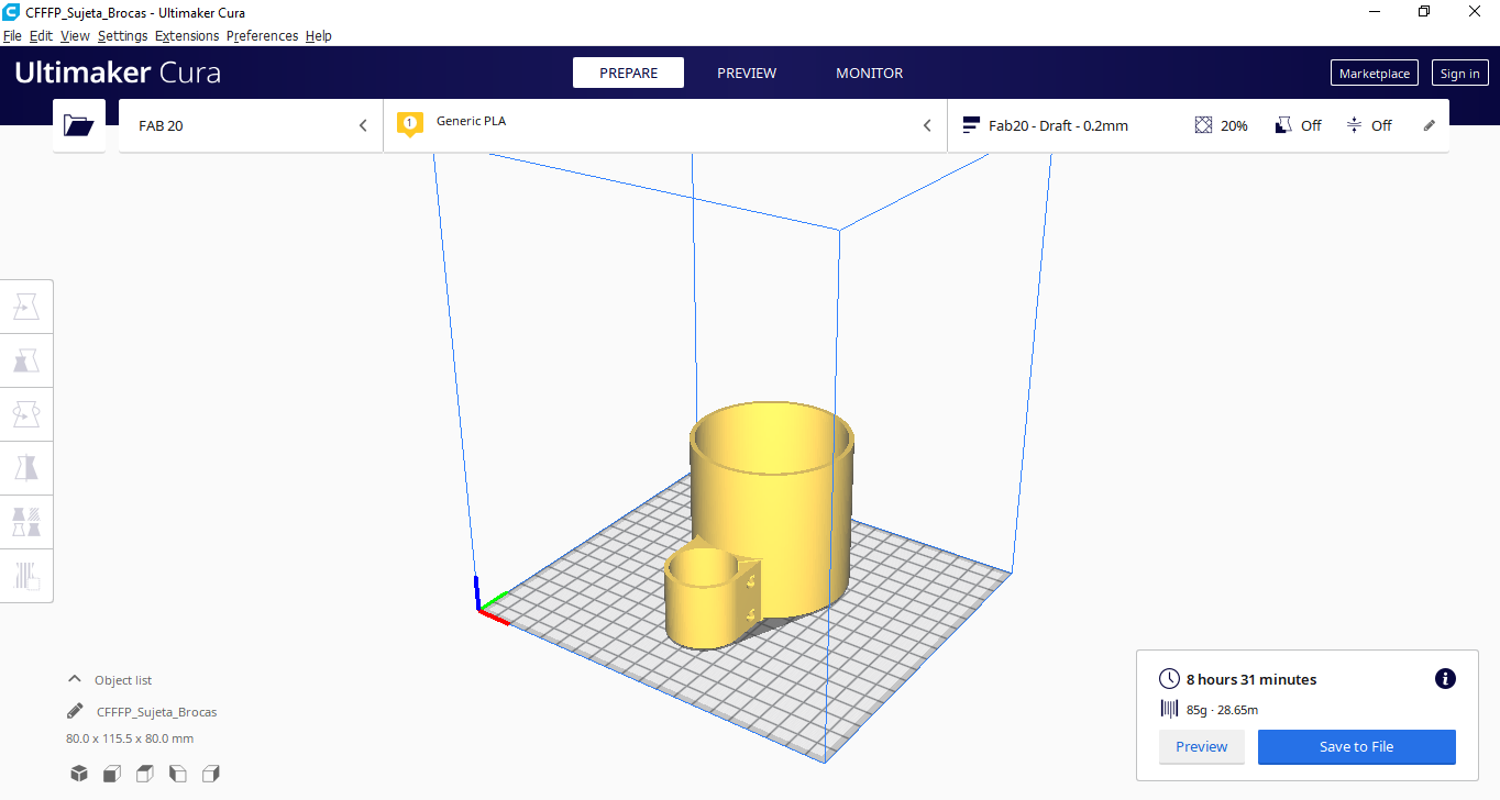
Test 2: Cylinder to drills
Cylinder to store drill bits, this is an addition that we require in the workshop to store bits:
We export the design in an STL file, for printing, We slice the designed piece, achieving a time of 8 hours and 31 minutes, to print:
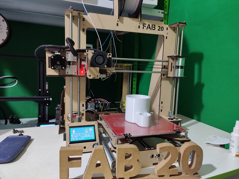
We start printing the GCODE file on the 3D printer
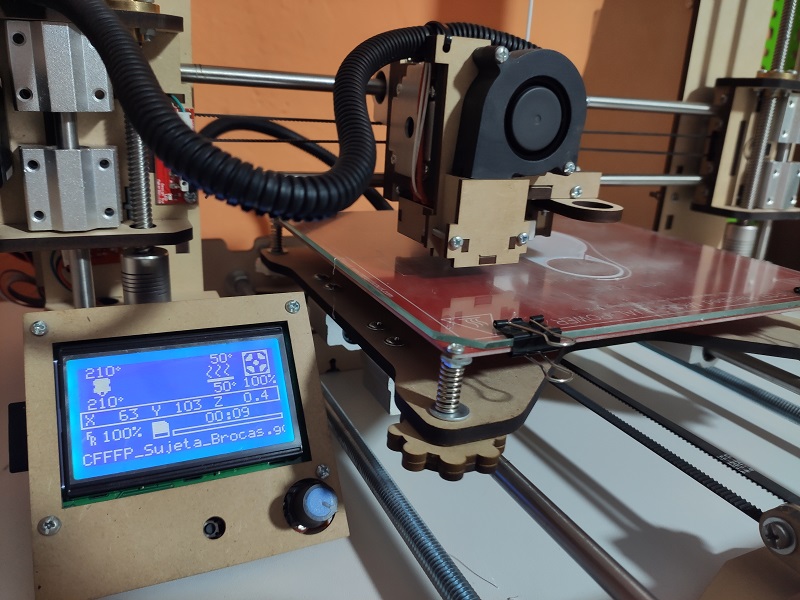
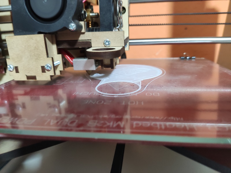
We can see it making the first layers:
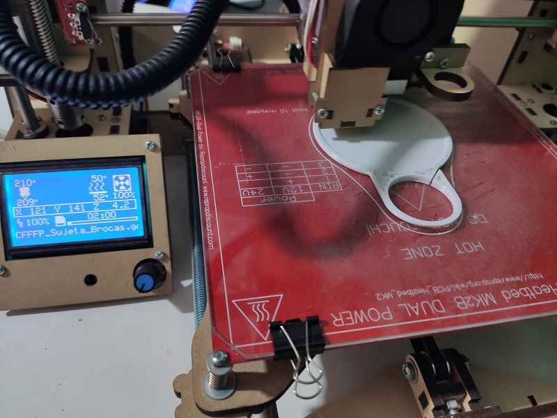
We can see the impression in full advance:
There we have the finished print:
We install the cylinder on the head of a drill bench, we can see the installation on the right side:
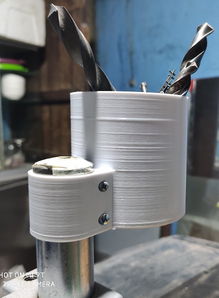
We install the cylinder on the head of a drill bench, we can see the installation on the left side:
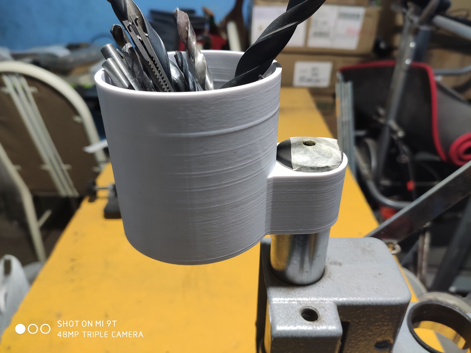
Here we can see the cylinder to store drill bits, installed and functional.
Designed Files
| Description | Files |
|---|---|
| Marlin | FAB_20-Marlin.zip |
| FAB 20 Printer 3D | FAB_20_Design-3D.zip |
| FAB 20 Printer 2D | FAB_20_Design-2D.zip |