3D Printer for Mashed Potatoes
This is my goal
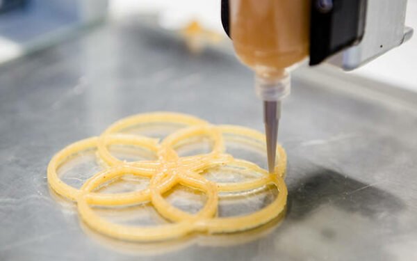
My final project is to design and manufacture a 3D printer for mashed potatoes, due to the need to customize food dishes in Arequipa-Peru.
Final Project: FAB 20 3D Printer for Decoration
For the realization of this project there are different stages, which we will divide into to turn them into milestones or objectives, which we would have mentioned in the following list:
- XYZ Structure This part was design in week 3: Computer Aided design
- FAB20 prototype sketch design
- Structure Design for movements in X, Y and Z axes
- Manufacture of structure for movements in X, Y and Z axes
- Assembly of structure of Movements in X, Y and Z axes
- Extruder This part was design in week 14: Invention Intellectual Propoerty and Income
- Extruder prototype sketch design
- Extruder Structure Design
- Extruder Manufacturing
- Extruder Assembling
- Electronic This part was design and manufacture in quarantine
- CAD Electronic Designing
- Electronic Manufacturing
- Electronic Assembling
- Software This part was design and manufacture in quarantine
- Marlin Firmware Configuration
- Calibration with Pronterface software
- Ultimaker Cura Software Configuration.
- Testing This part was design and manufacture in quarantine
- Sample with chocolate delicacy
- Sample with cakes
- Sample with mashed potatoes
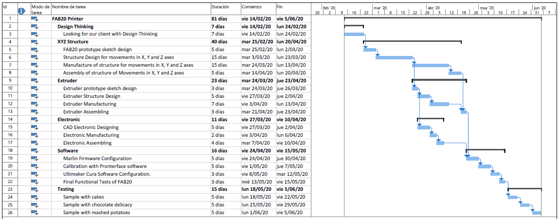
Project Execution Plan
For the execution of this project, the following activities plan was prepared with the required times:
XYZ Structure
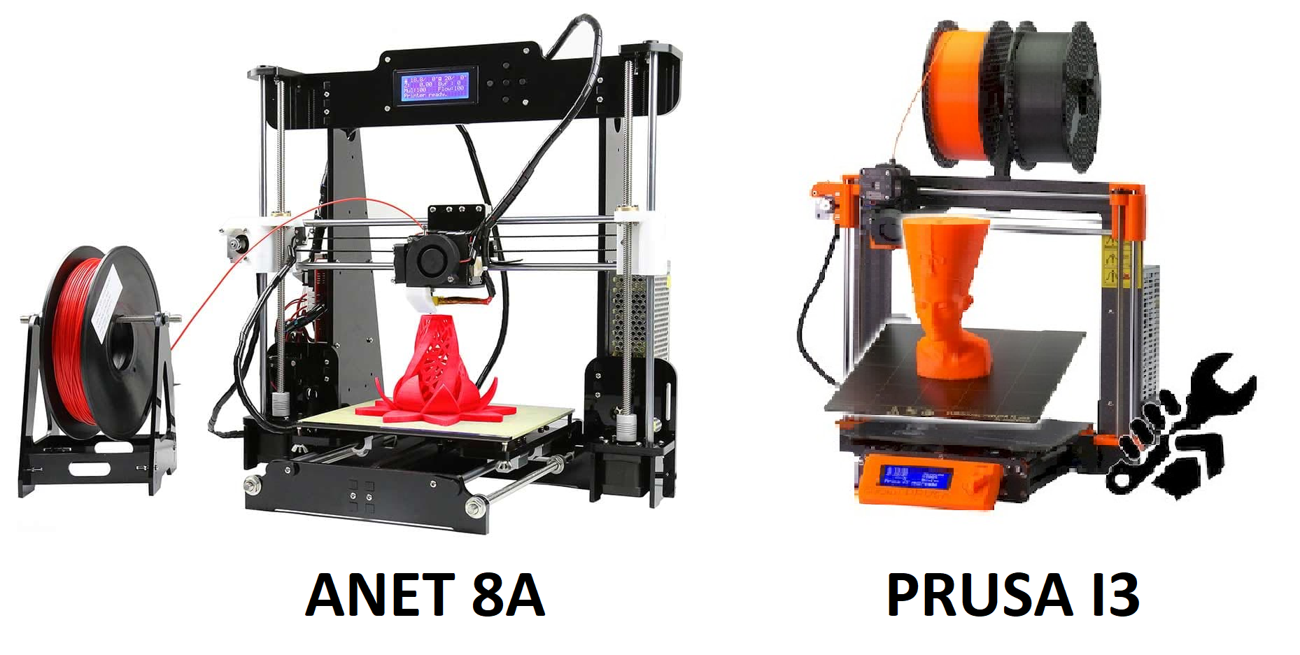
For the structure and to achieve the movements of X, Y and Z we started with him by proposing a sketch of the structure, based on the models of the most commercial printers, the ANET A8 and Prusa I3 printers.
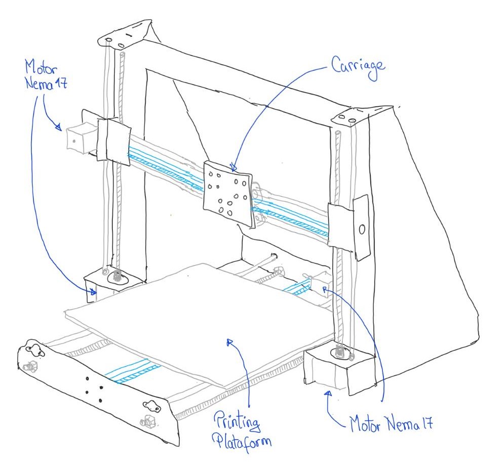
FAB 20 prototype sketch design
Inspiration:
Based on the current models of the most commercial 3D printers, we propose the present sketch:
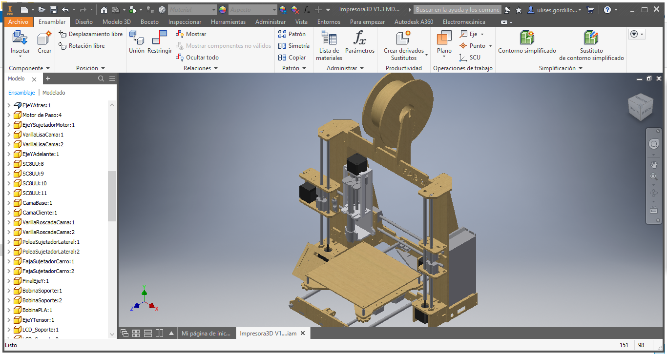
Structure Design for movements in X, Y and Z axes
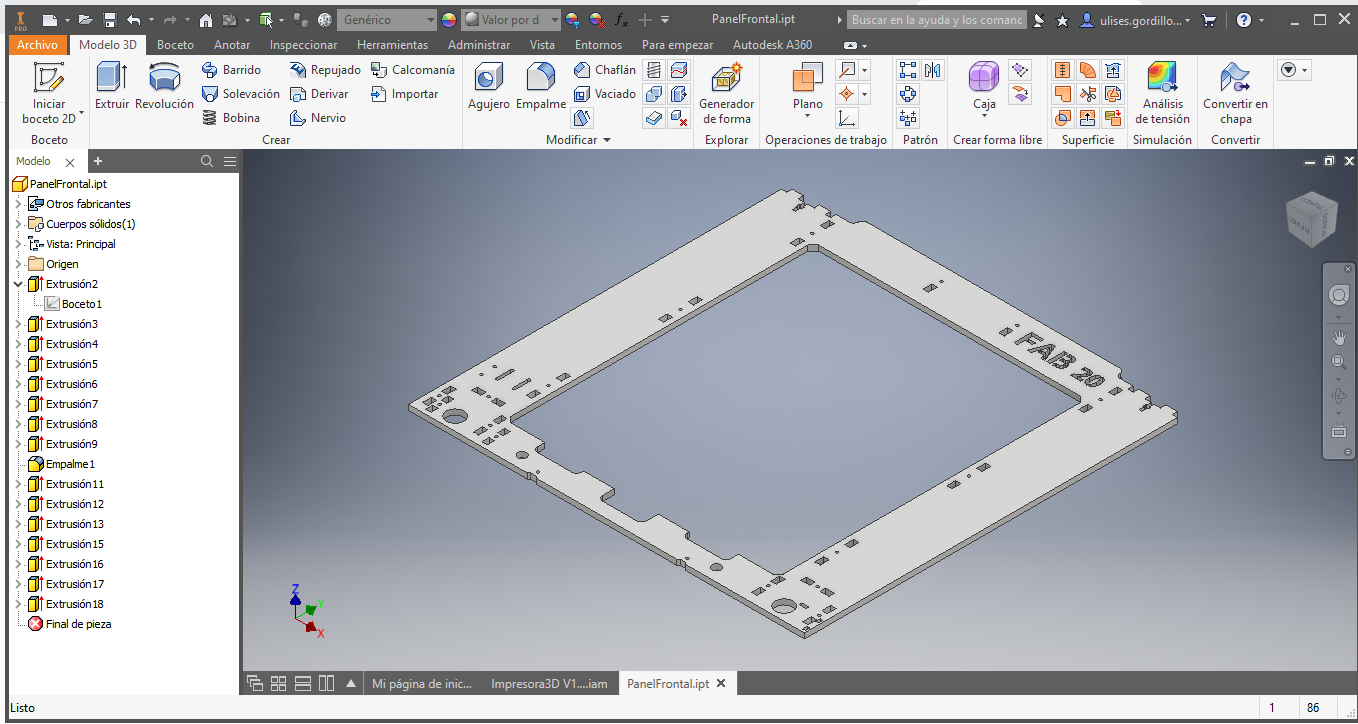
For the design of the structure of the 3D Printer, I started with the central frame that held the entire structure.
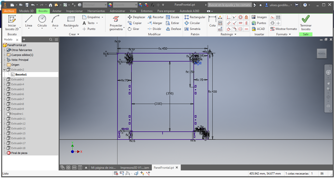
This would be the design of the main frame:
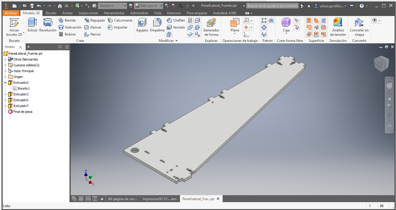
Then design the side studs that will hold the electronics and the 12V source.
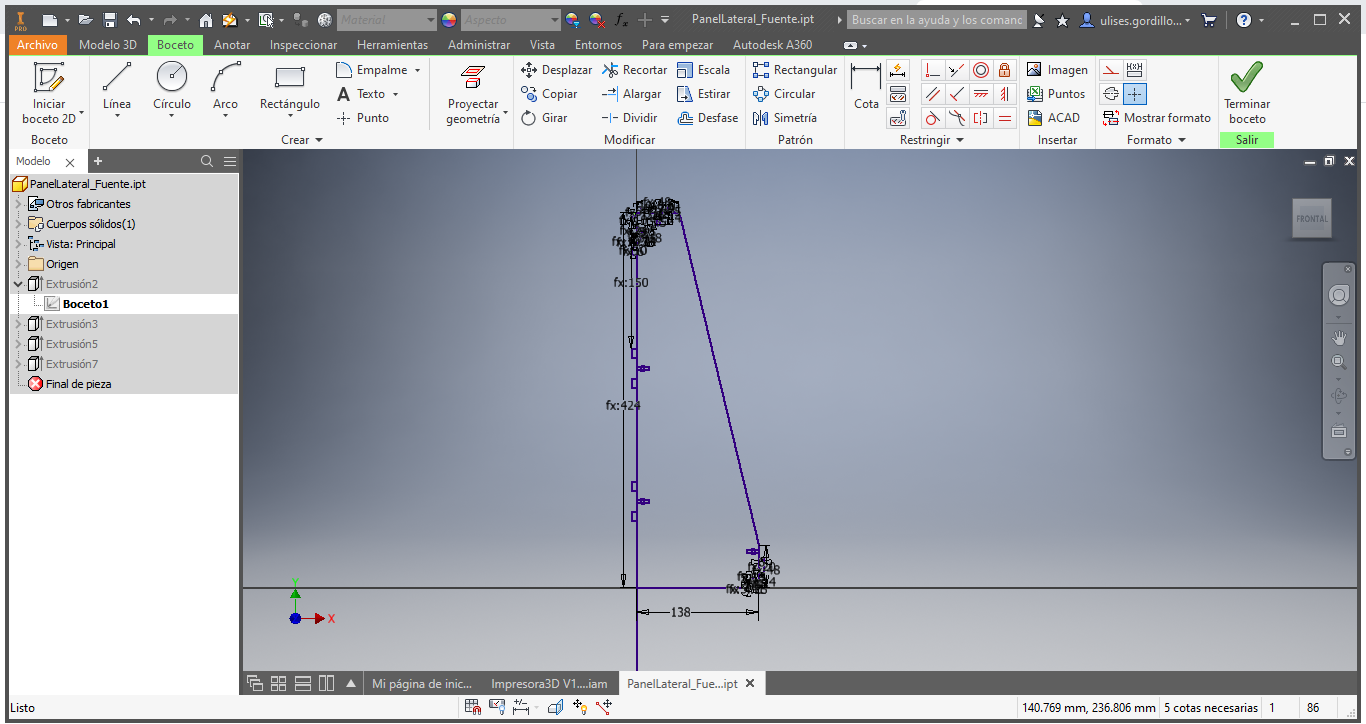
These are the side posts:
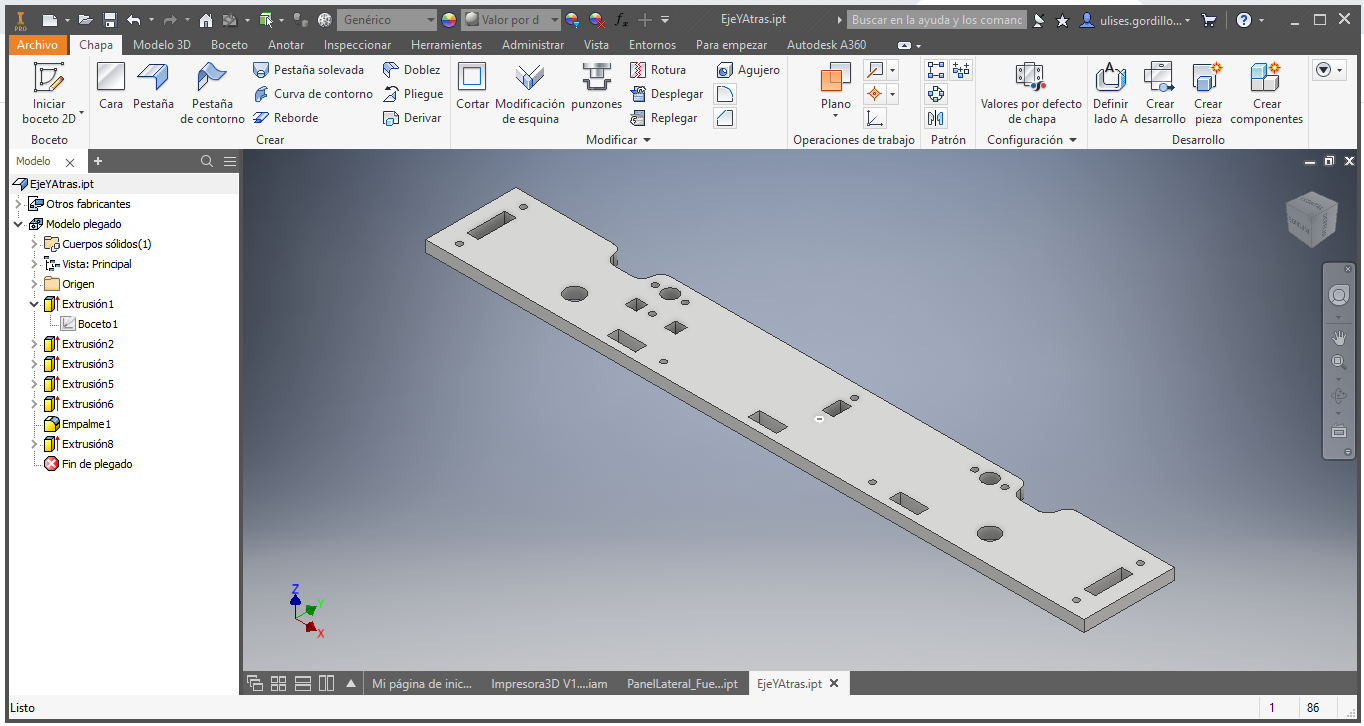
Then we designed the back of the printer, it is holding the sliding base of the printing platform.
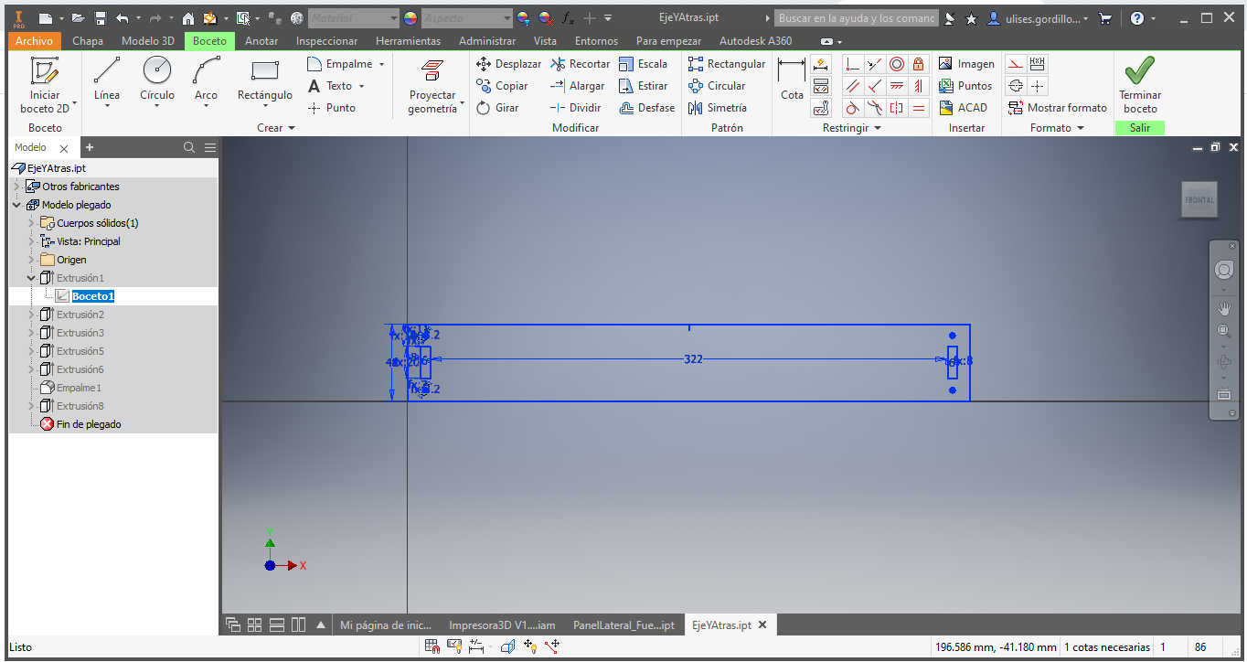
this is the bracket from the back:
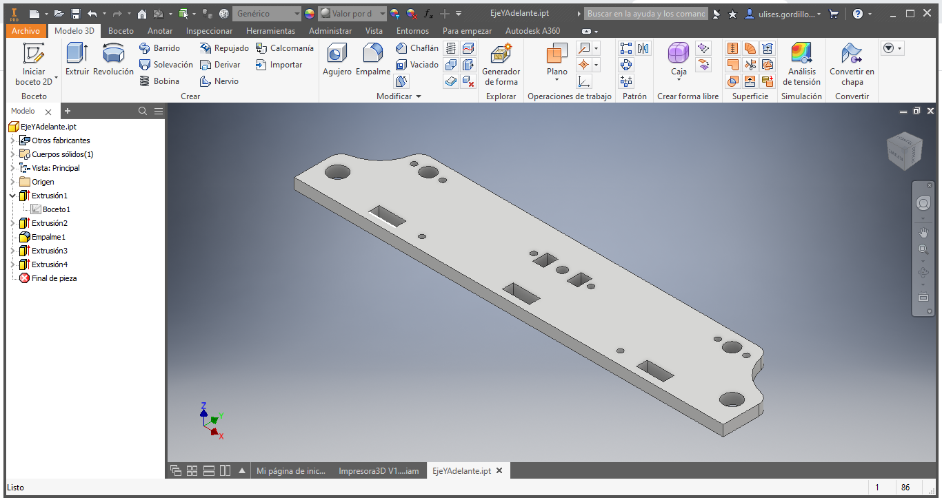
Then we designed the front part of the structure, which will also support the printing platform.
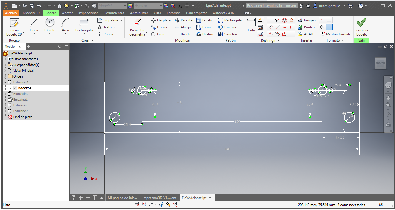
This would be the front support.
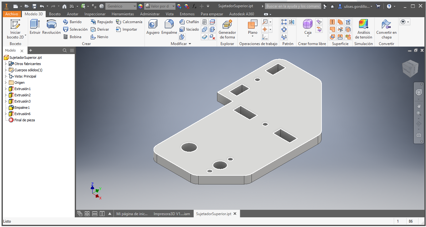
Then we design the upper union of the frame and the side posts of the 3D printer
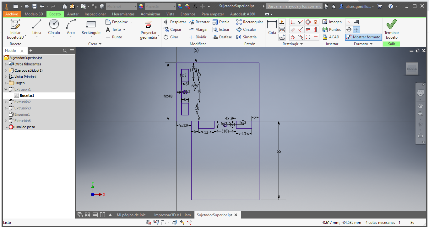
This would be the superior union:
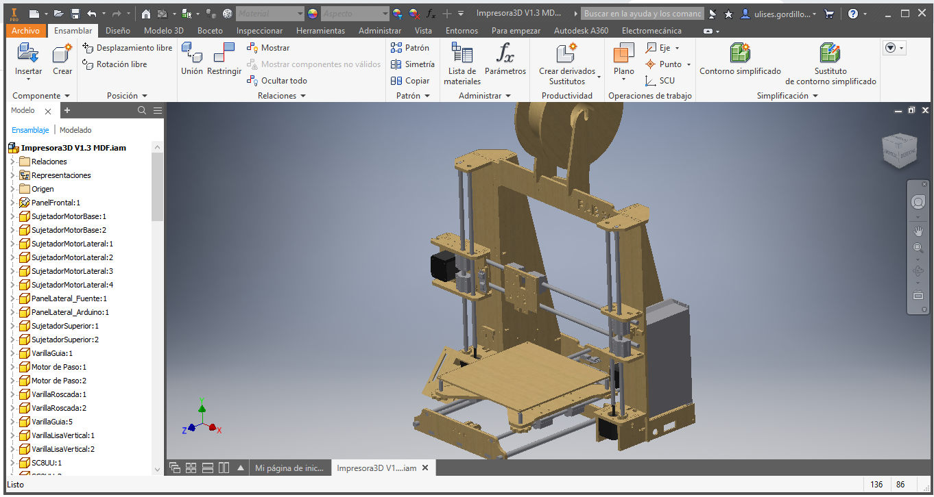
We start to assemble the printer and correct the measurements or joints:
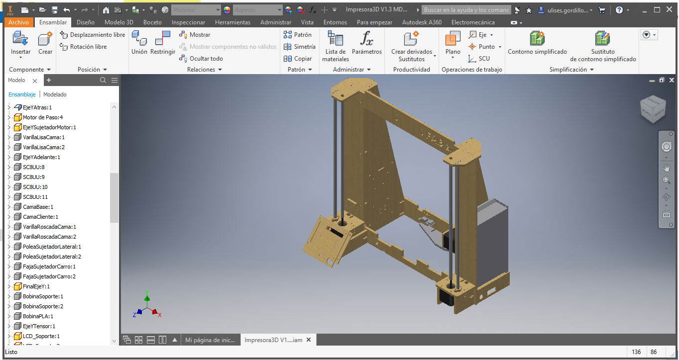
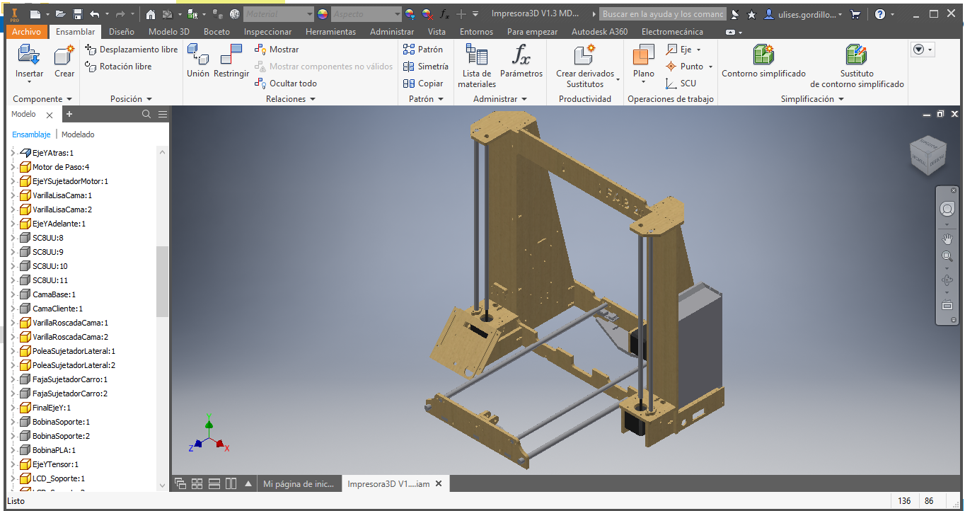
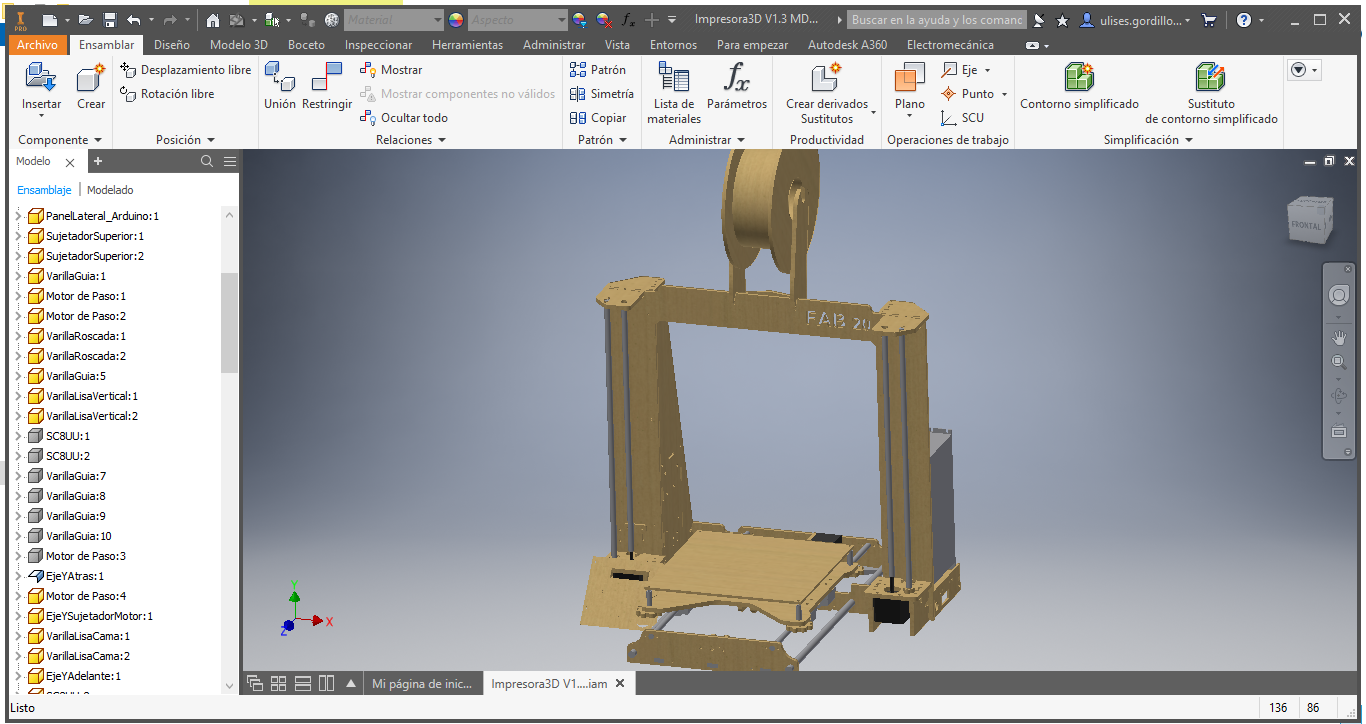
Then we add the rods and support for the build platform.
Now we add the printing platform
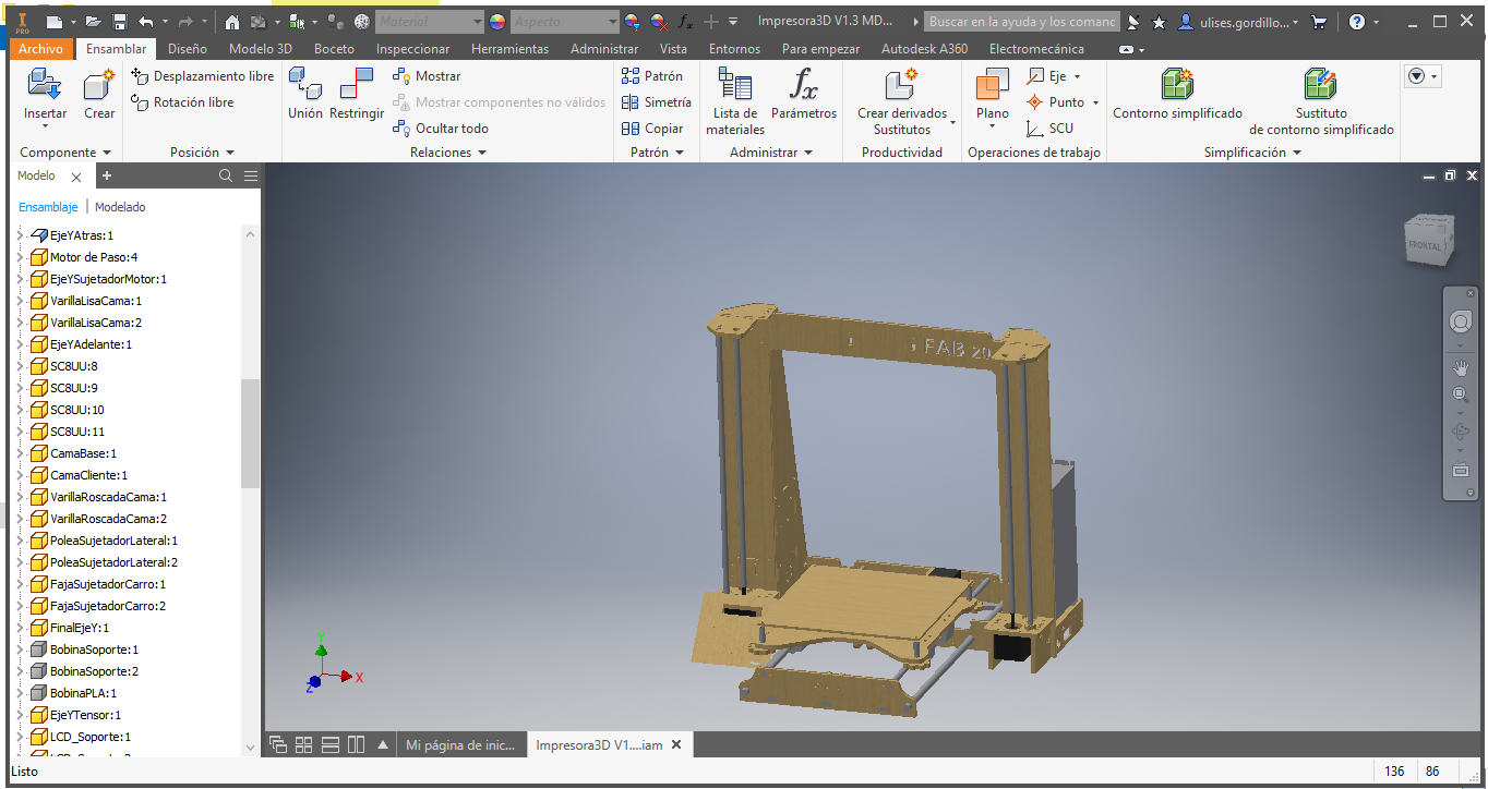
For purposes of use as a molten filament printer, we will place a support to hold filament rolls.
Then we add the metal rods, and the parts of the X axis.
We can see from another angle to observe the details.
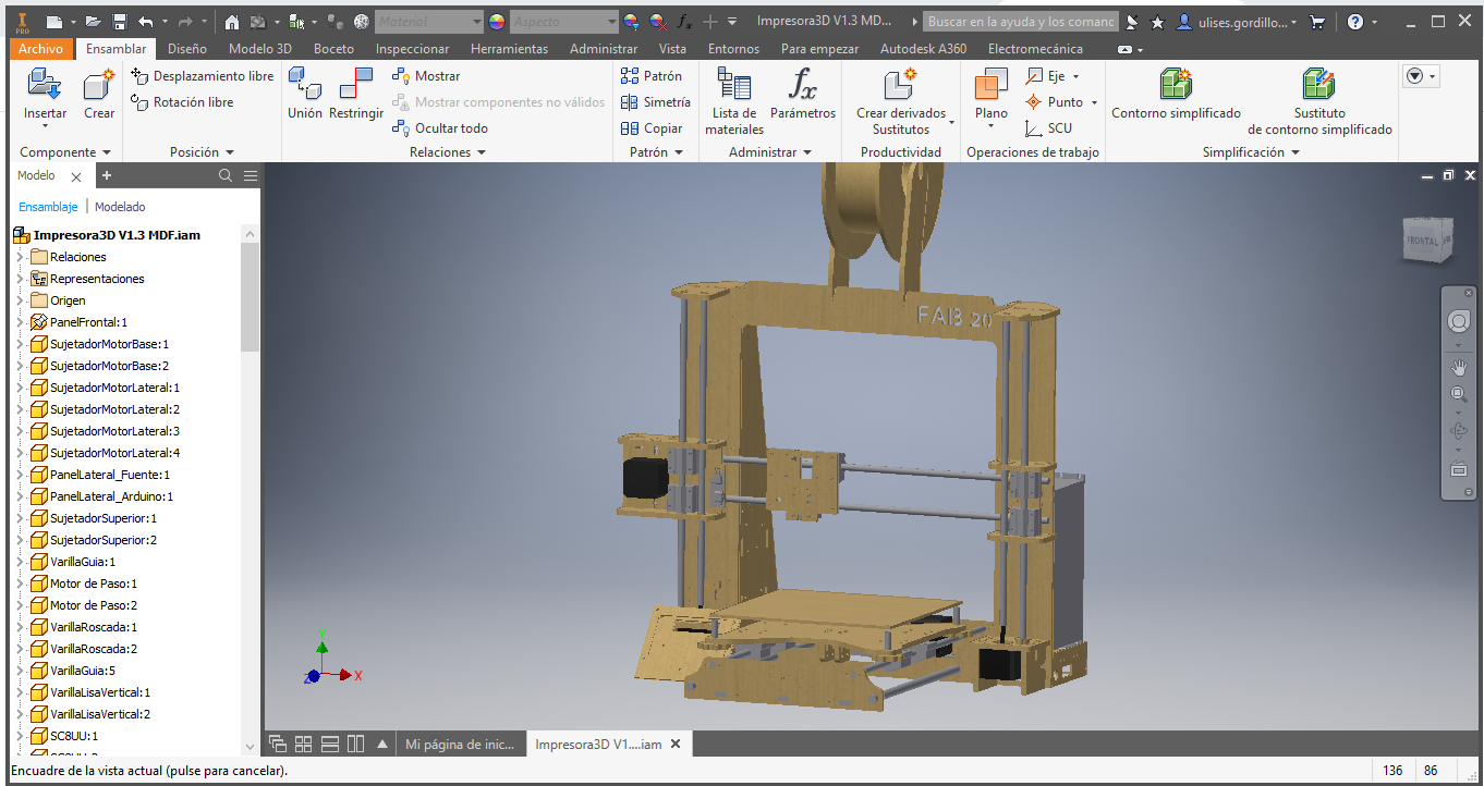
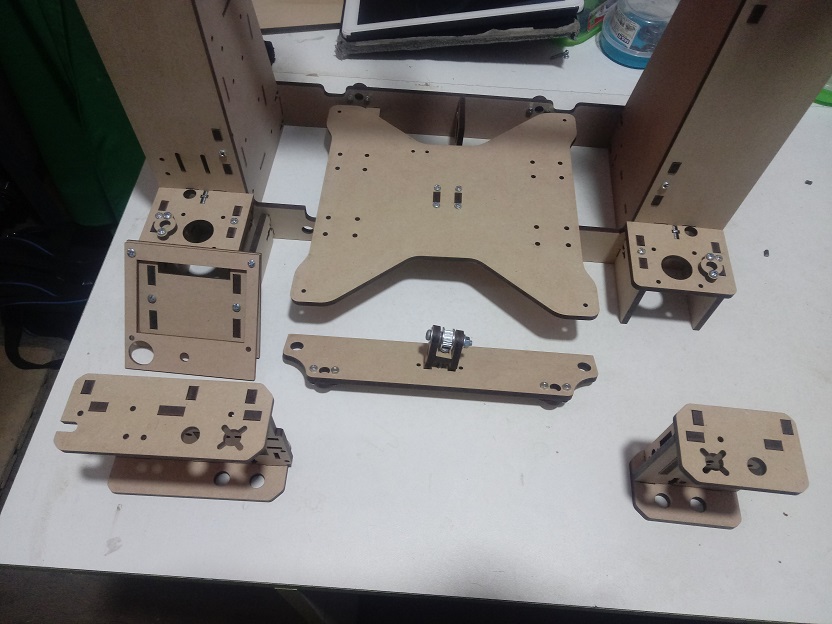
Here we have the parts of the FRAME, side PARANTS and accessories.
Here we have the parts for the Z axis
Here we have the parts for the extruder but with fused filament (if required).
Here we have the parts for the LCD screen and accessories
Here we have the parts for the electronics box and accessories
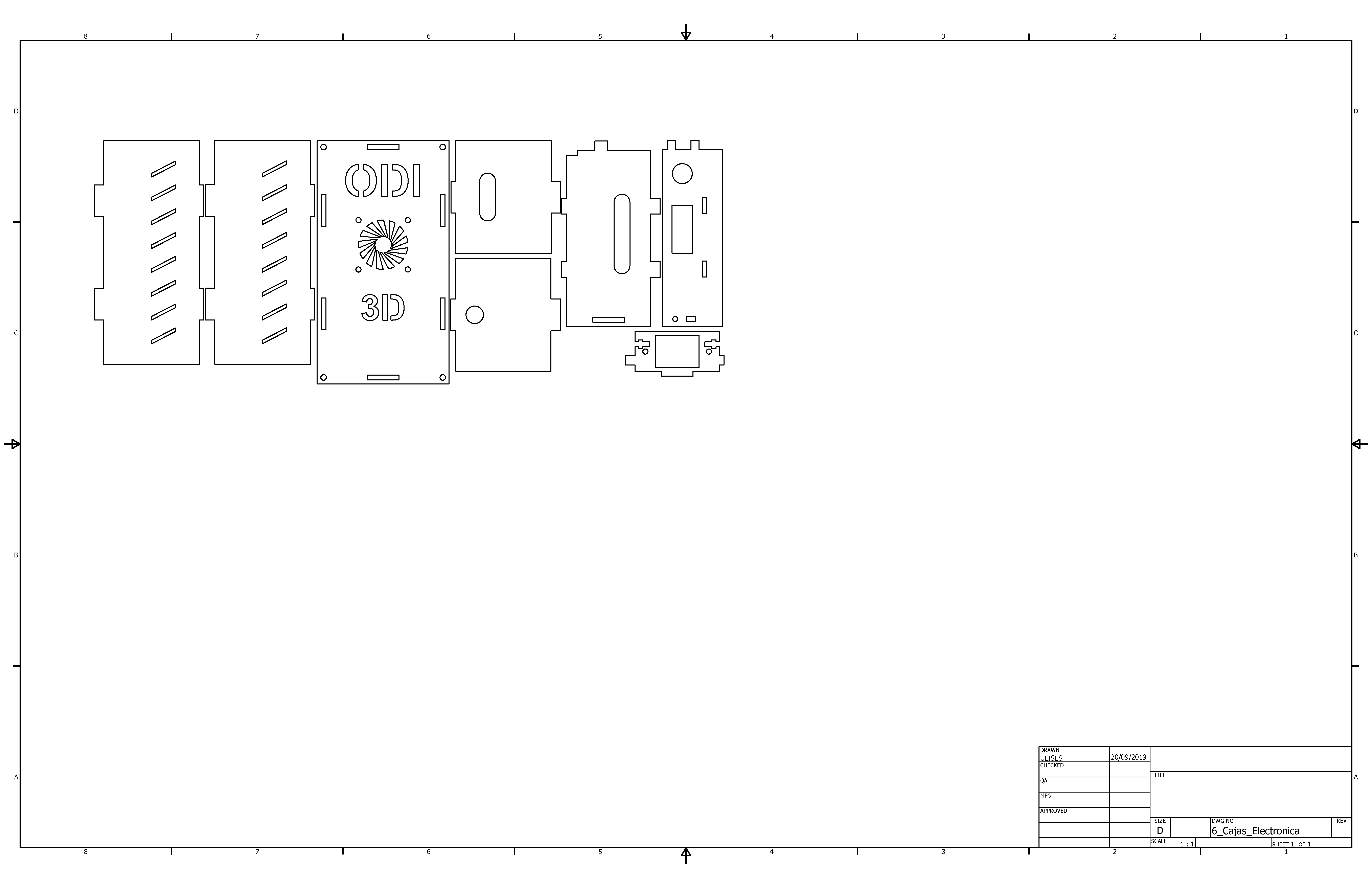
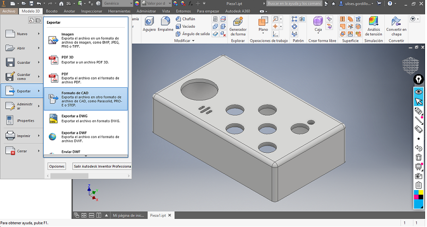
Manufacture of structure for movements in X, Y and Z axes
First, we export the 2D designs, and edit them for laser cutting in the RDwork Software.
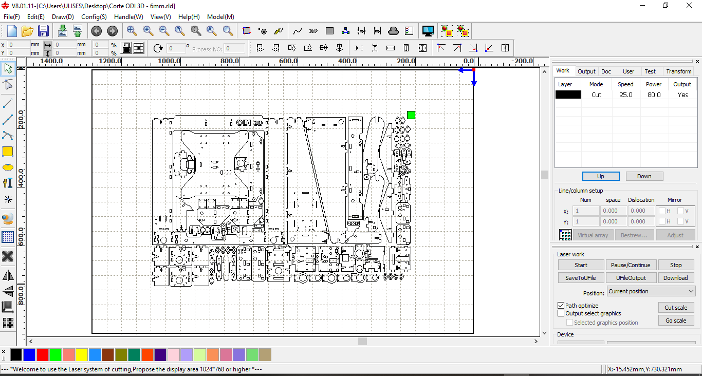
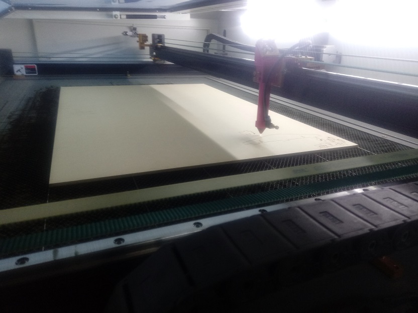
We can see the material placed and ready to cut the design of the FAB 20
Here we see the interface with the laser cutter.
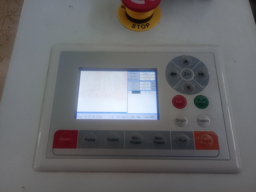
We can see the manufacturing process:
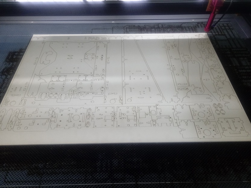
Here we have the parts to assemble the 3D printer
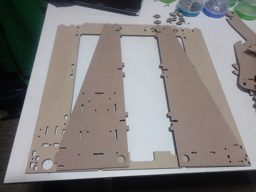
Assembly of structure of Movements in X, Y and Z axes
First we assemble the frame, the side posts, and the back:
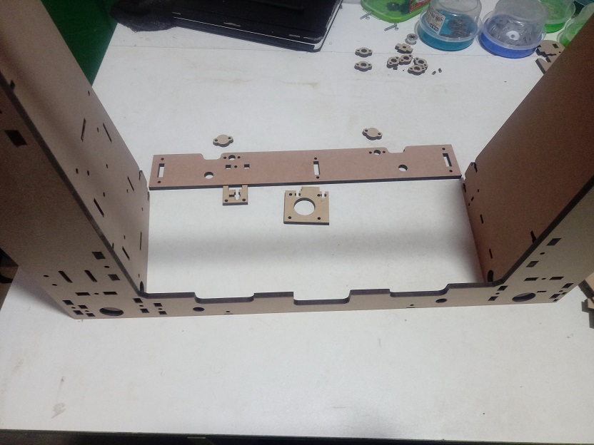
Then we add the front part
Here we have the front part armed.
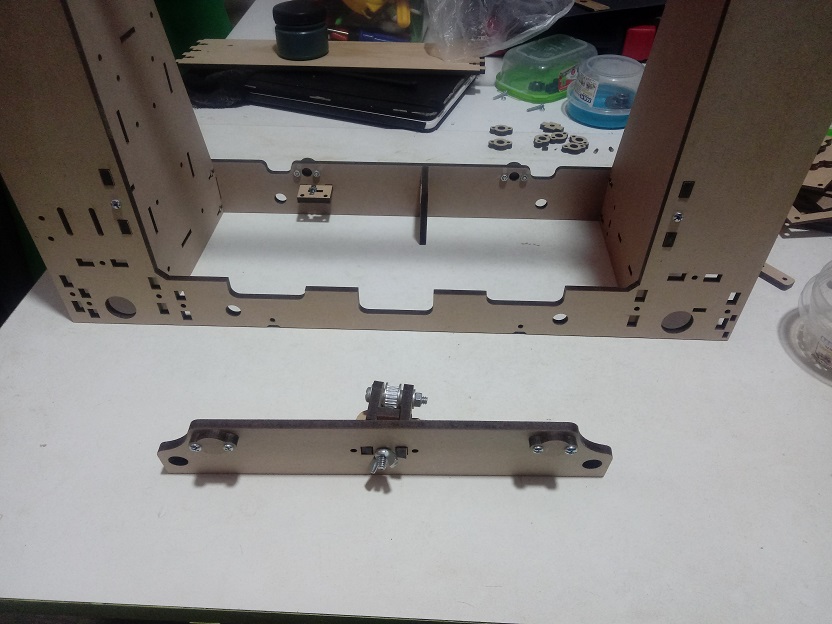
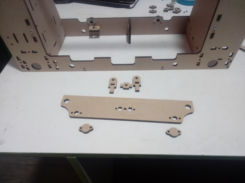
Then we add the frame joints and the side studs.
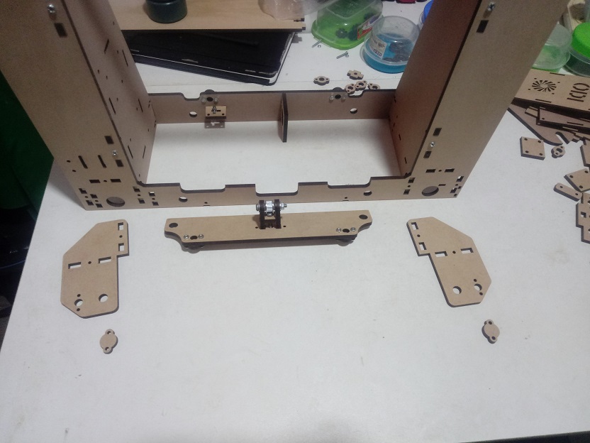
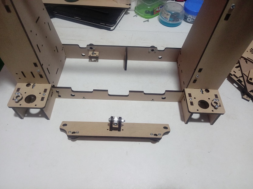
Then we add the brackets for the stepper motors.
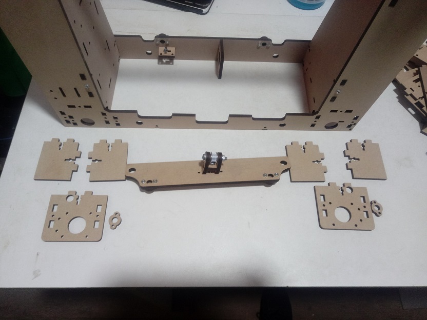
Here we have the brackets for stepper motor
Here we have the parts for the X axis
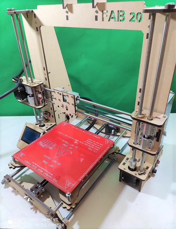
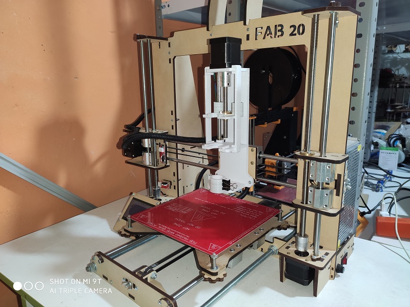
So here we have the structure with all the parts manufactured and assembled.
Extruder
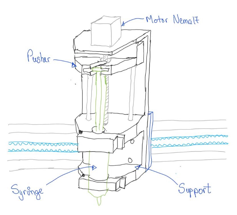
Extruder prototype sketch design
For the material injection work we use an extruder that pushes the cold material through a syringe.
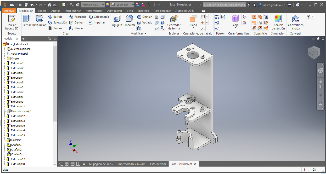
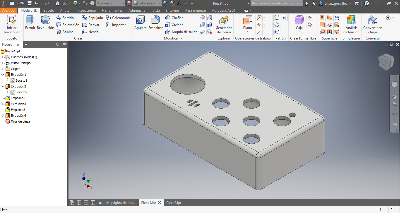
Extruder Structure Design
We started by designing the main base of the extruder
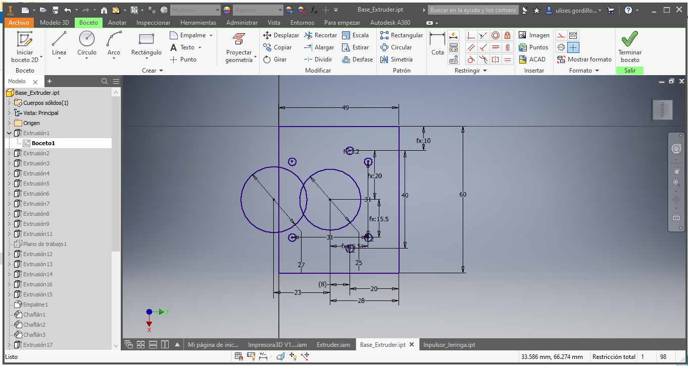
Here we have the base of the extruder
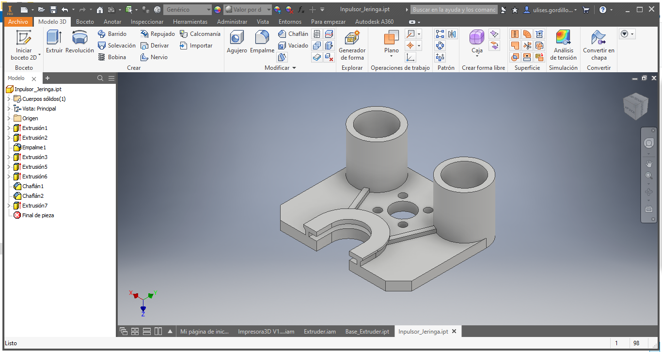
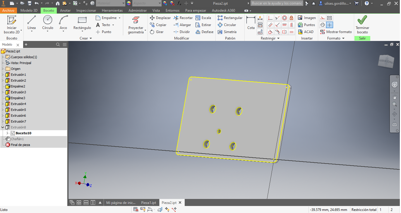
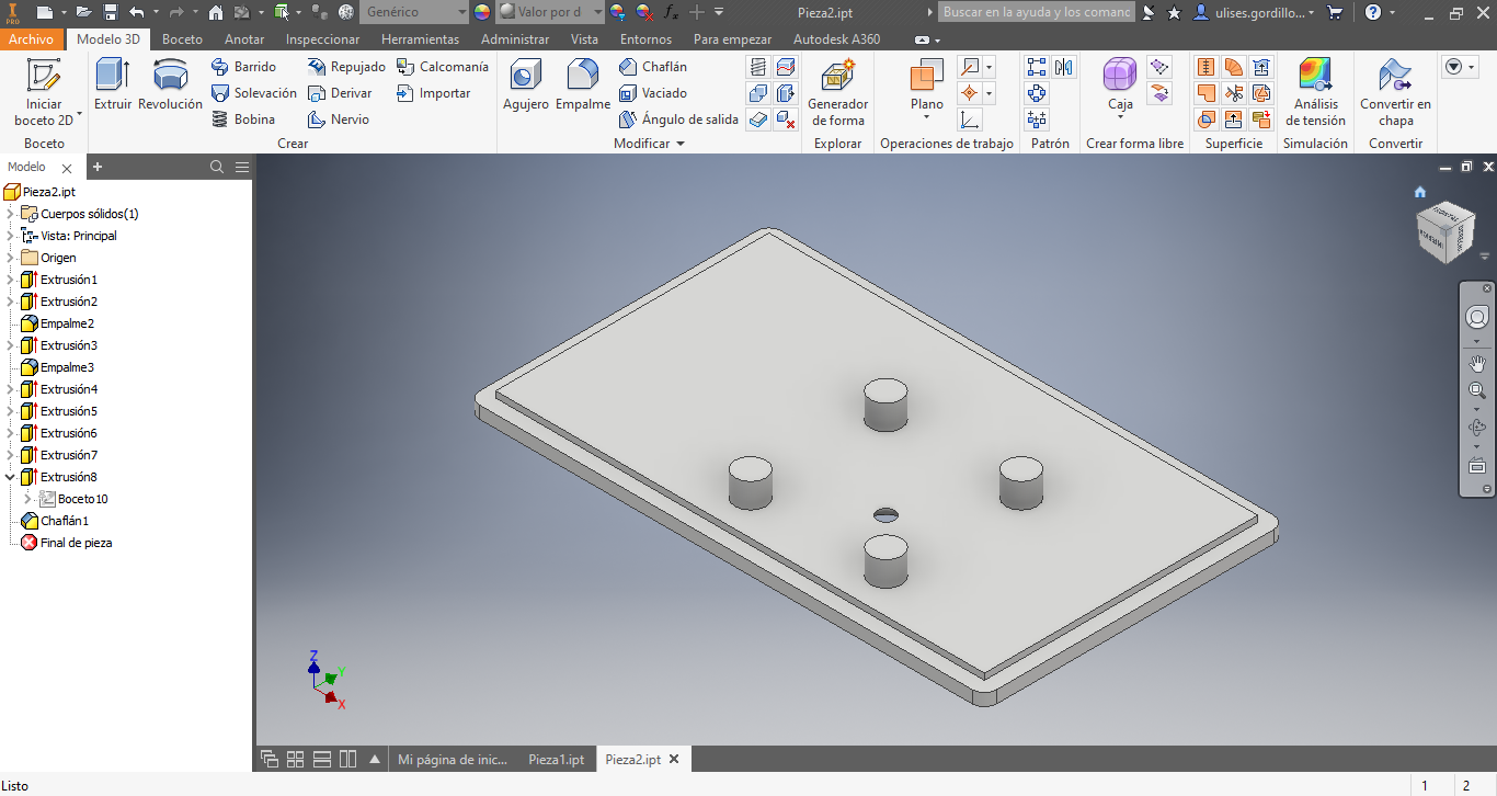
Then we design the push piece for the syringe.
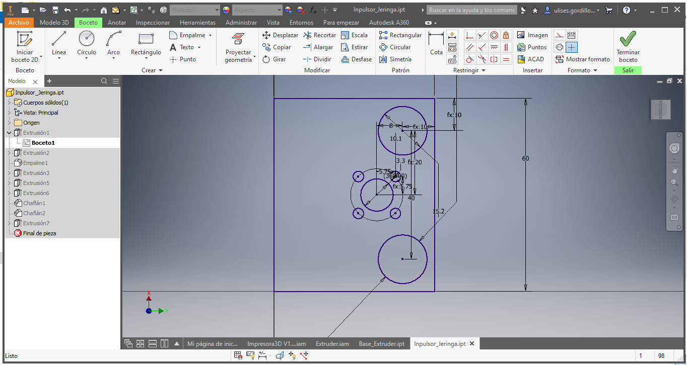
Here we have the push piece for the syringe.
We assemble the Extruder parts to obtain an image of its installation
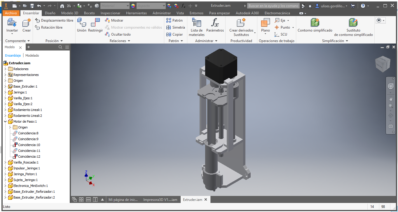
Finally we install it in the X, Y and Z motion structure. This would be the 3D printer on the part of the structure and the extruder.
Extruder Manufacturing
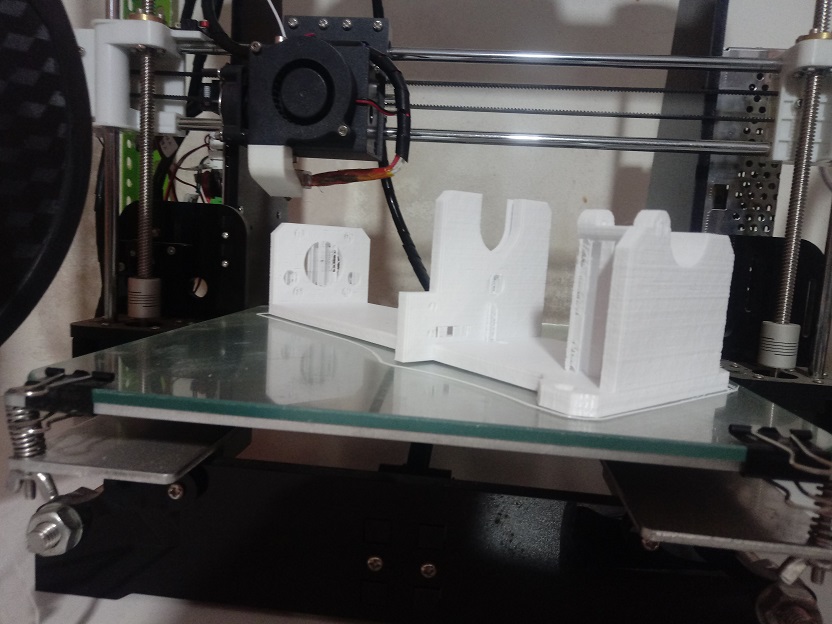
Parts are printed on a filament cast printer
Here we see the advancement of 3D printing
Here we have the finished base:
Extruder Assembling
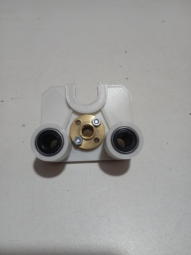
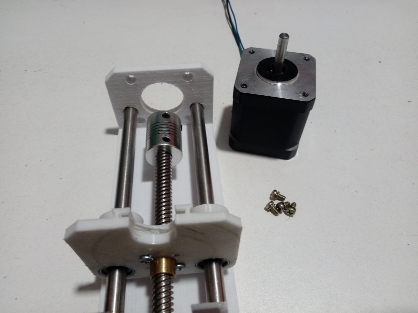
First we prepare the pieces for the sliding piece.
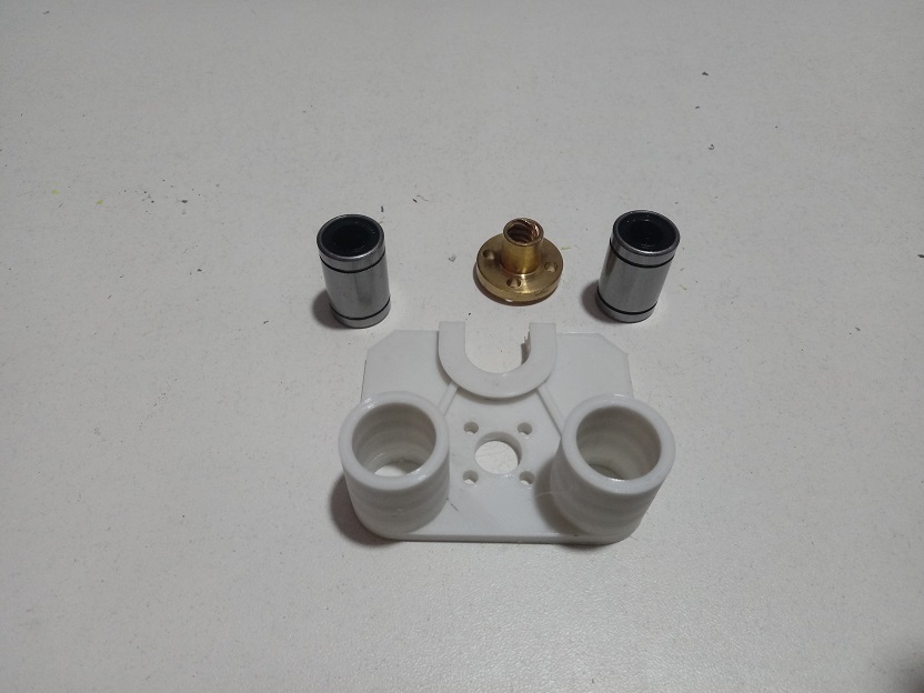
Here we have the finished sliding pieces:
Then we choose the accessories for the slide, such as the metal rods.
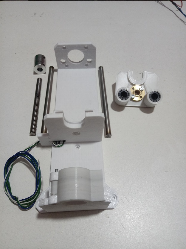
Here we have the sliding base installed
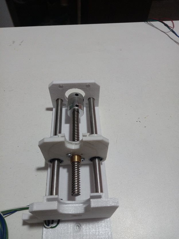
We prepare a Nema 17 engine
Here we have the extruder finished assembling it.
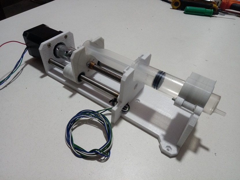
Here we show the final installation of the 3D printer
Electronic
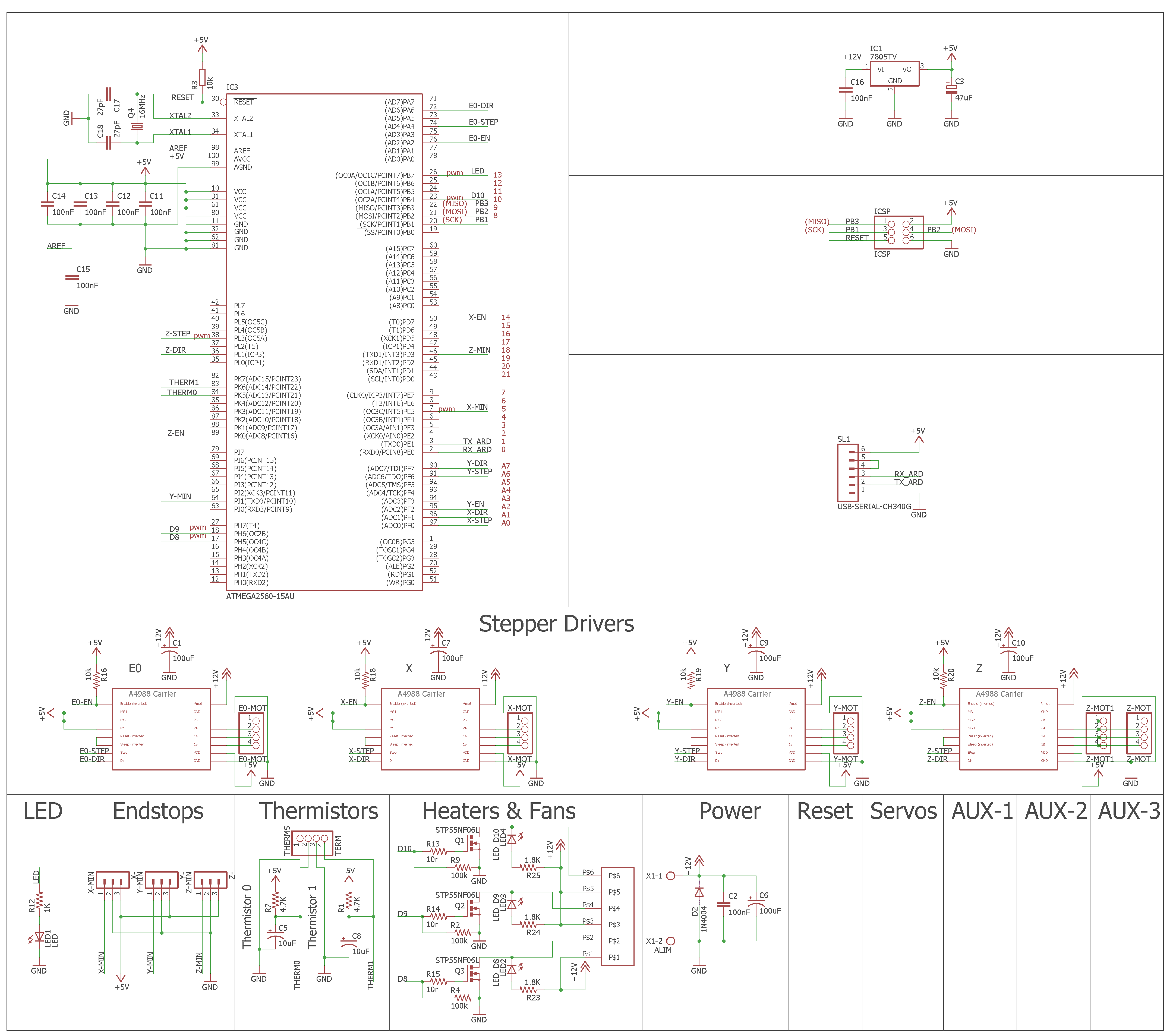
This part the initial idea is paused because we do not have some components, we have part of the work done but it was not completed due to the impact on the inputs of the restrictions of the COVID19 pandemic in my country. We worked with an Atmega2560 microcontroller and the A4988 drivers.
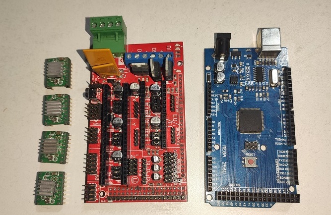
But we will replace it with commercial cards like the Arduino Mega and the Ramps 1.4, which was the cards we relied on.
CAD Electronic Designing
It is the schematic, it is basing of Arduino Mega + RAMPS 1.4 schematics, it is use in 3D printer of filaments:
It is the design with the wire top and bottom:
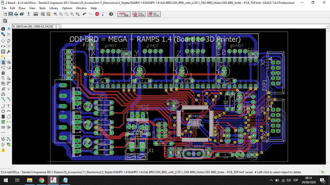
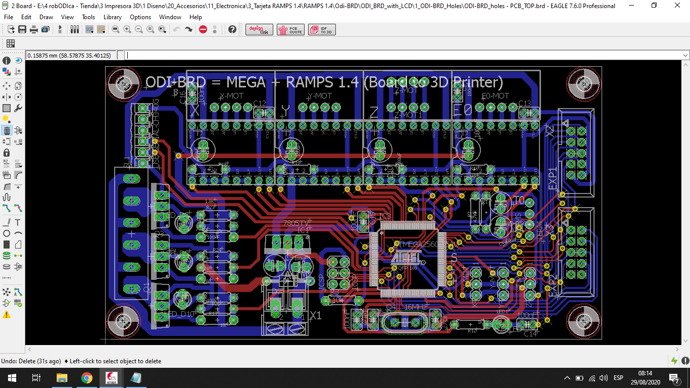
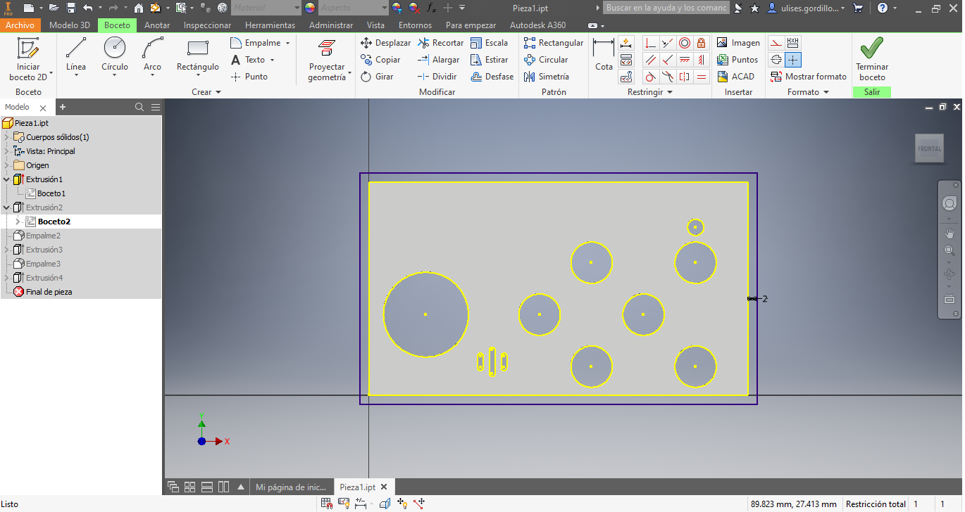
We need add the holes to sopport the board:
Electronic Manufacturing
This part has not yet been developed due to a lack of electronic components, since the pandemic stopped some related activities.
Electronic Assembling
To work we choose to change it to commercial boards, a board based on RAMPS 1.4 was developed that connects to an Arduino Mega with the Atmega2560 microcontroller, this board combines the two electronic boards, the Arduino Mega + RAMPS 1.4, used in the REPRAP Community.
The connection diagram is based on the RAMPS 1.4 documentation from its official website RAMPS 1.4
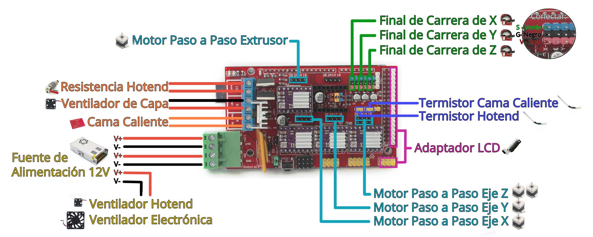
This would be the electronics to use:
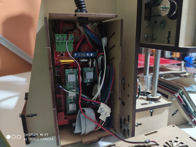
This is the electronics assembled and placed in its box
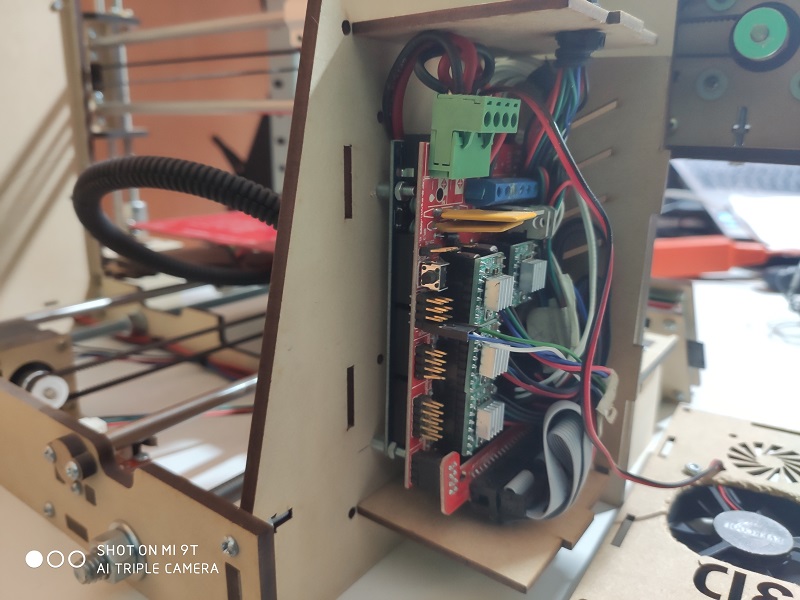
Here we have another view, the connection is the same recommended by the REPRAP community
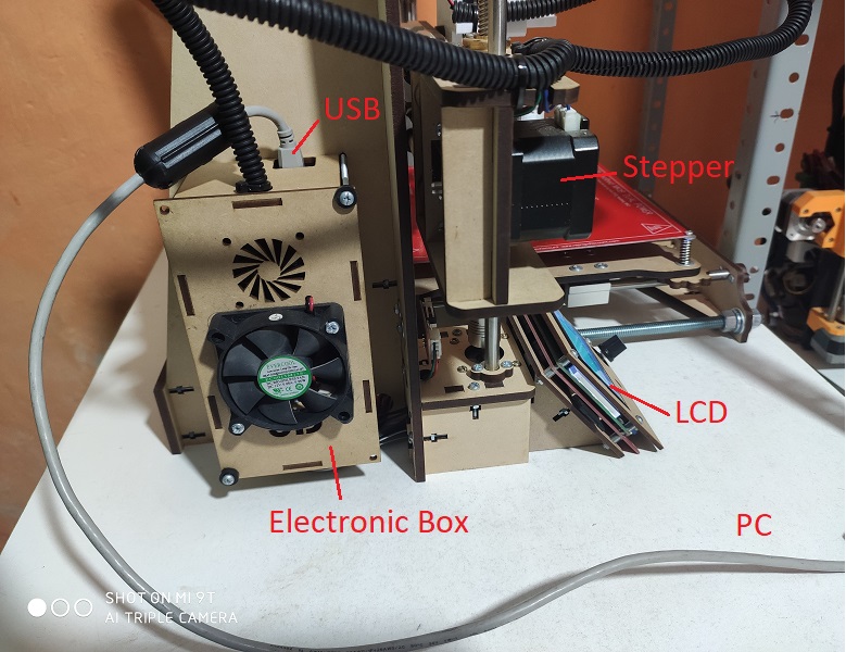
In this image we can connect the 3D printer to the computer, through a USB cable
Software
For the development of the software part we will work with software that we have in the Reprap community, with the following operating structure:
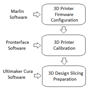
Then, to work with the software configuration we will have the following items:
- Marlin Firmware Configuration
- Calibration with Pronterface software
- Ultimaker Cura Software Configuration.
Marlin Firmware Configuration
We can download the marlin firmware for 3D printer from the following page Official Marlin Page
Let’s choose versions 1.1.9, because it is a version for 8 bit microcontrollers since we will use the Atmega2560 as microcontroller for the 3D printer
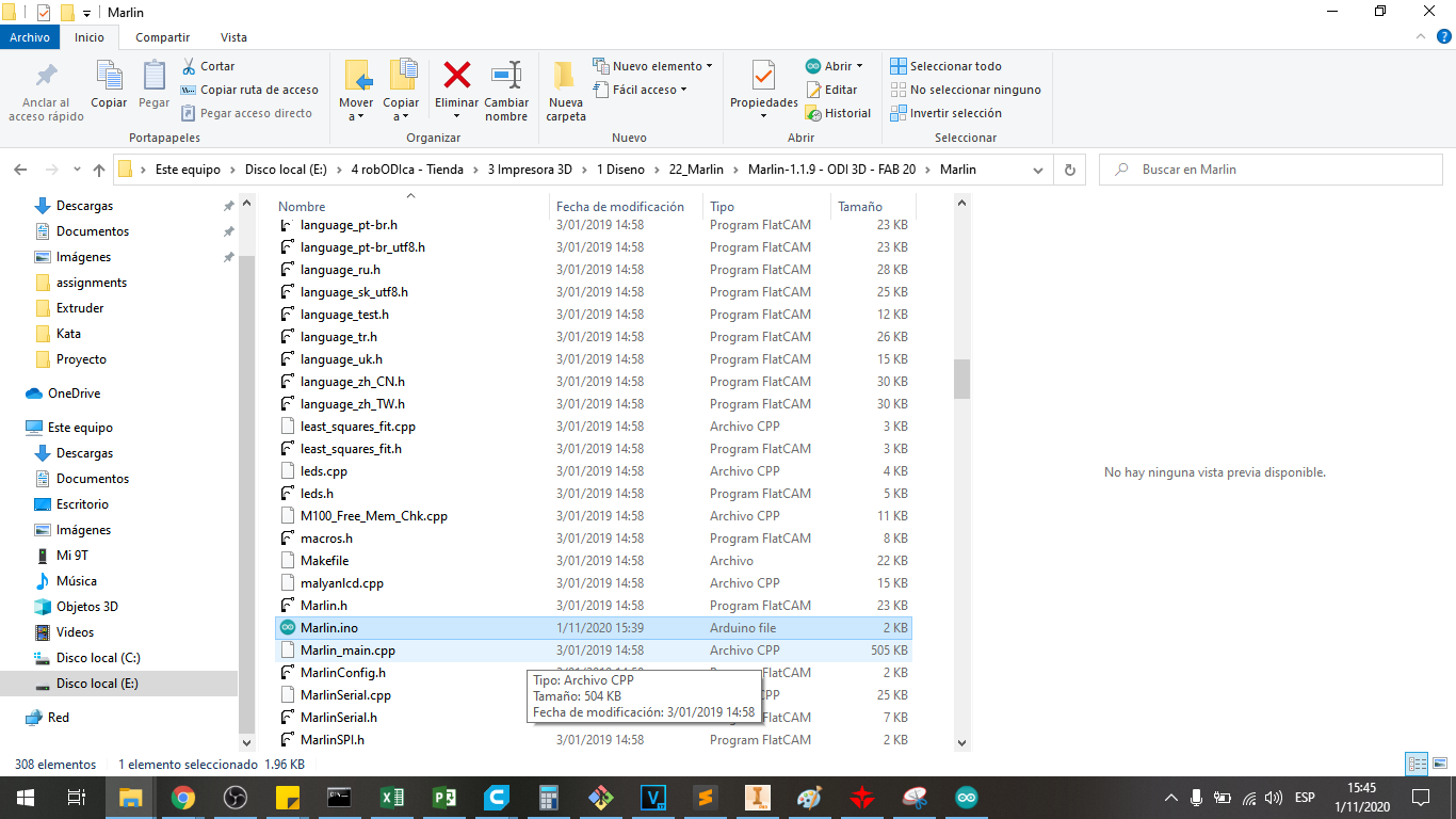
Unzip the downloaded file and go to the Marlin folder and choose the Marlin.ino file
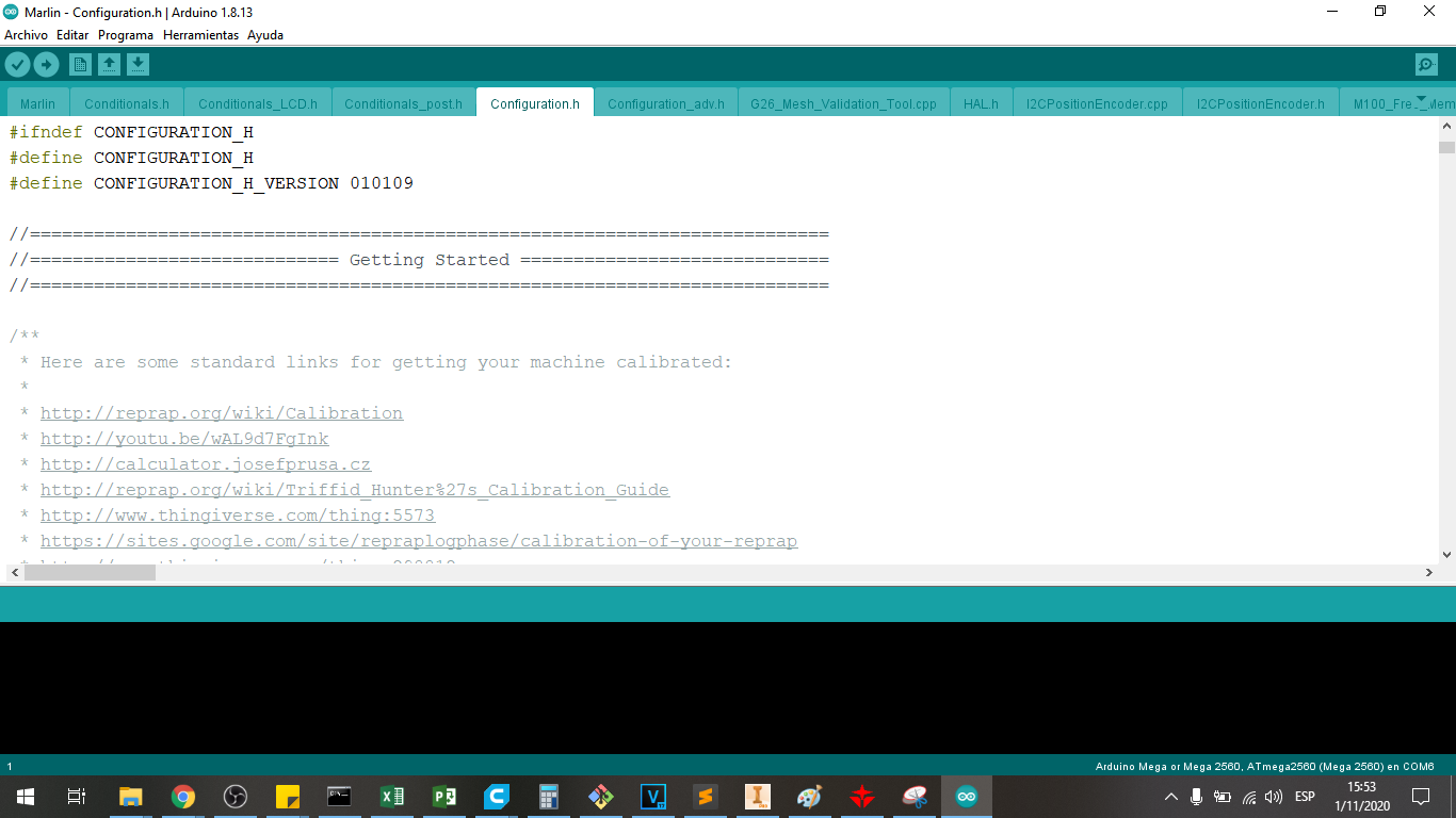
Go to the file tab Configuration.h where I will modifiy some parameters to the FAB20 Printer:
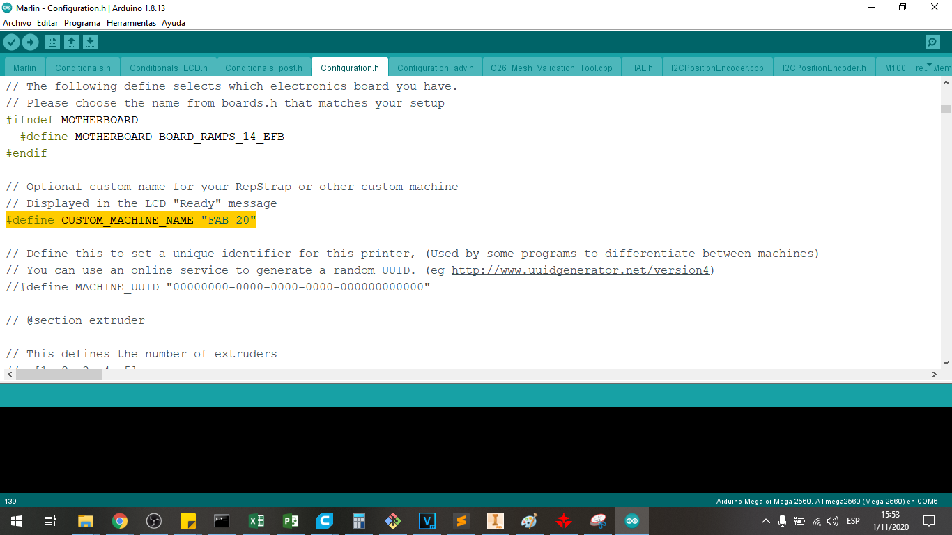
To modify the name of the machine:
#define CUSTOM_MACHINE_NAME "FAB 20"
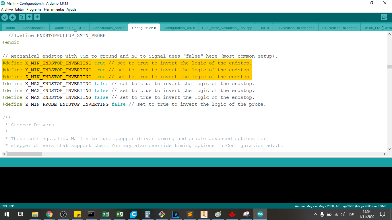
We must define the direction of operation of the limit switches for the X, Y and Z axes, this can be done in the following line:
    #define X_MIN_ENDSTOP_INVERTING true
    #define Y_MIN_ENDSTOP_INVERTING true
    #define Z_MIN_ENDSTOP_INVERTING true
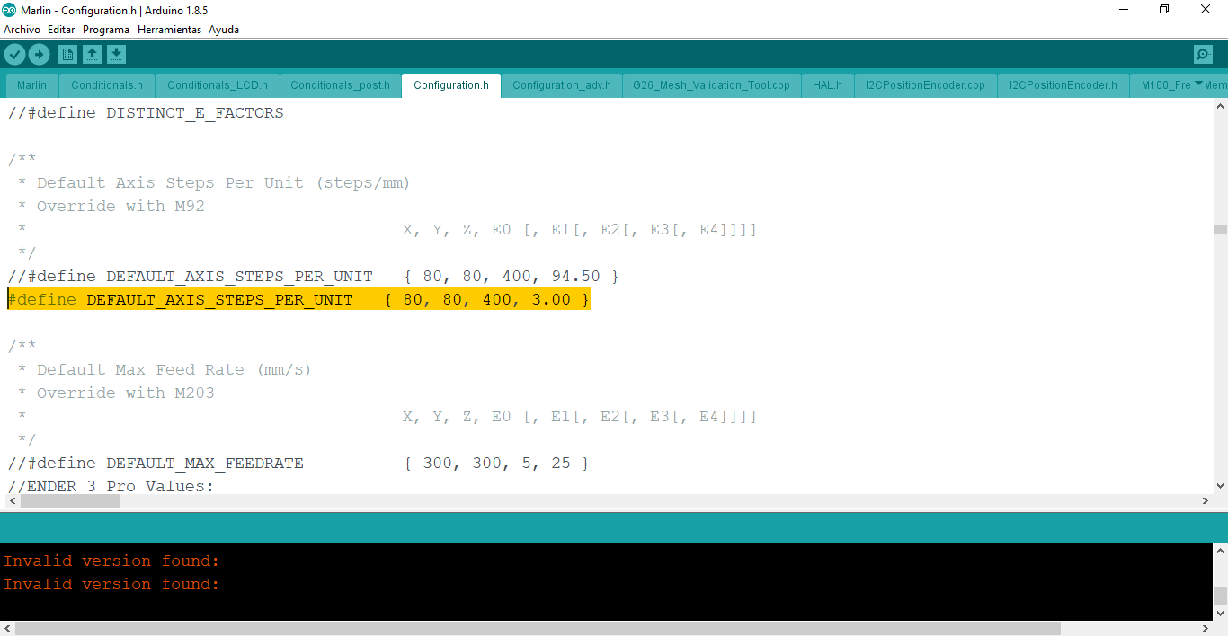
We must define the steps per unit of advance, that is, the steps per millimeter of advance, this can be done in the following line:
#define DEFAULT_AXIS_STEPS_PER_UNIT { 80, 80, 400, 3.00 }
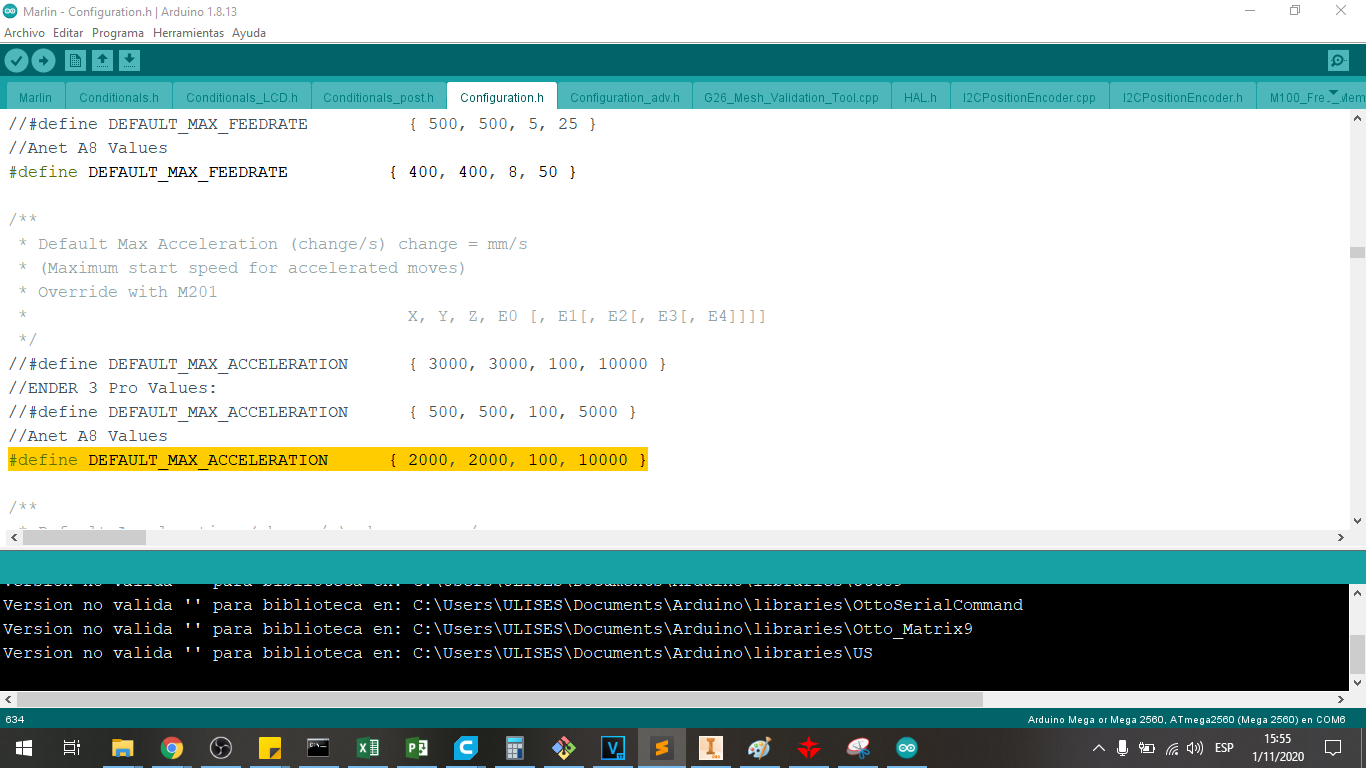
We must define the acceleration of each of the motors to control the starting or braking mode in the movements, this can be done in the following line:
#define DEFAULT_MAX_ACCELERATION { 2000, 2000, 100, 10000 }
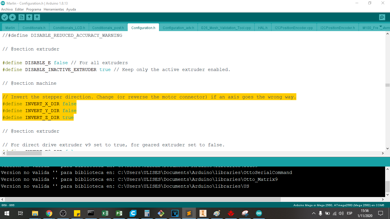
We must define the directions of the motor movements to have the correct advance in X, Y and Z, this can be done in the following line:
    #define INVERT_X_DIR false
    #define INVERT_Y_DIR false
    #define INVERT_Z_DIR true
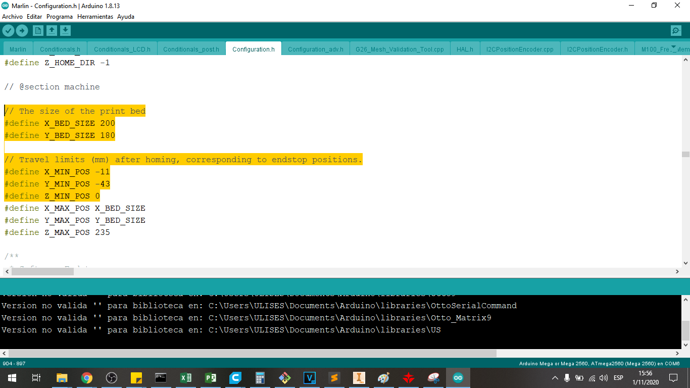
We defining the size of the print bed 200mm in X and 180mm in Y
    #define X_BED_SIZE 200
    #define Y_BED_SIZE 180
The positions of the end of races are not in 0,0,0 of the heatbed, then we need to indicate this offset, it is the travel limits (mm) after homing, corresponding to endstop positions in X. Y and Z axis:
    #define X_MIN_POS -11
    #define Y_MIN_POS -43
    #define Z_MIN_POS 0
Then, we have uploaded this program to the arduino mega for its calibration, we choose the serial port, we choose the arduino mega 2560 and upload it.
These are the most relevant parameters to be able to configure our printer, then when we test with the Pronterface software we will see what corrections we can make.
Calibration with Pronterface software
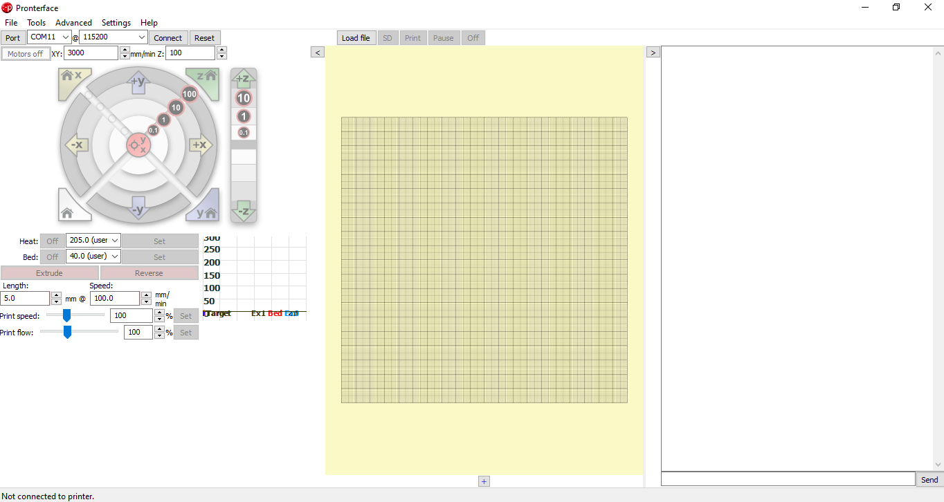
We use Pronterface software to configure the printer parameters, we can download it from the following Official Pronterface Page
Let’s choose Printrun-win-18Nov2017, because it is a newest version of the software.
We open the program:
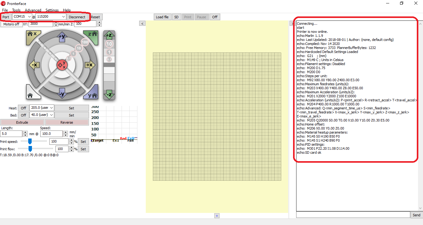
We choose the serial port, in my case it is COM15, we choose the communication speed of 115200 baud, and we press CONNECT
Then a printer connection message is displayed:
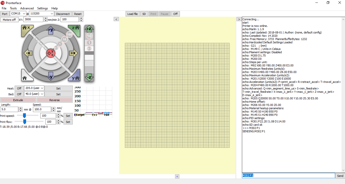
To carry out the configuration, we send the command of M302 P1, to be able to make cold movement of the 3D printer, so that we can calibrate the step of the extruder.
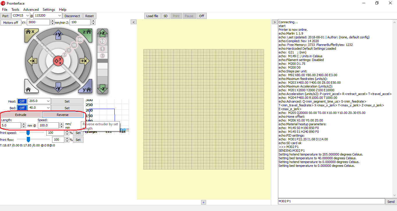
Then we can already extrude cold to calibrate the steps per millimeter for the extruder, in our case it would be 94.50, which was placed in the marlin instruction:
#define DEFAULT_AXIS_STEPS_PER_UNIT { 80, 80, 400, 3.00 }
We can calibrate the steps per millimeter using the commands to test the movement in X, succeeding in verifying that this value is 80:
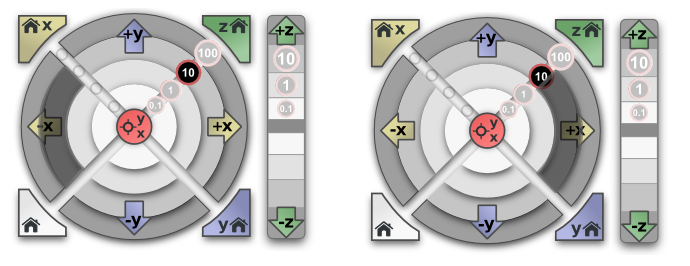
We can calibrate the steps per millimeter using the commands to test the movement in Y, succeeding in verifying that this value is 80:
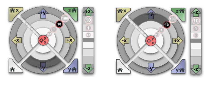
We can calibrate the steps per millimeter using the commands to test the movement in X, succeeding in verifying that this value is 400:
#define DEFAULT_AXIS_STEPS_PER_UNIT { 80, 80, 400, 3.00 }
Said data placed in the marlin instruction:
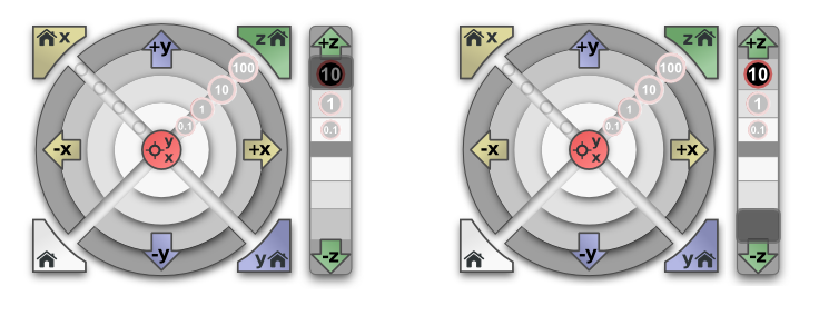
For the extruder it was tested with several advance values, giving rise to a value of 3.00 as the one that gave us a proportional injection for the design.
#define DEFAULT_AXIS_STEPS_PER_UNIT { 80, 80, 400, 3.00 }
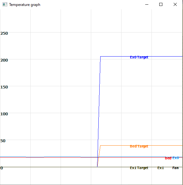
Finally we can calibrate and check the operation of the heaters and temperature sensors for the extruder and the heatbed.
Ultimaker Cura Software Configuration.
The slicer is the program that converts the STL file into a GCODE command that the 3D printer executes to create the 3D object.
We use Ultimaker Cura software to slice the designed file in 3D CAD software, we can download it from the following Official Ultimakes Page
Let’s choose the newest version of the software.
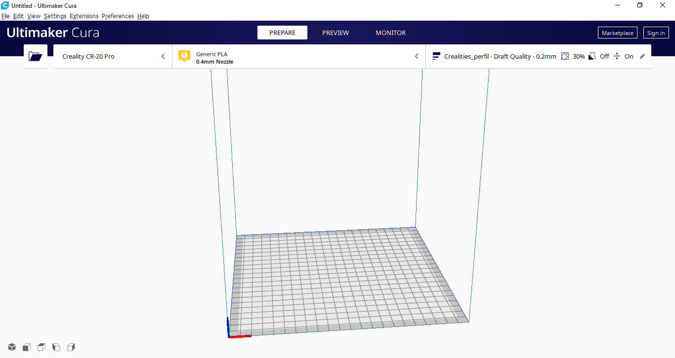
We open the program:
This is the program interface to slice the STL files:
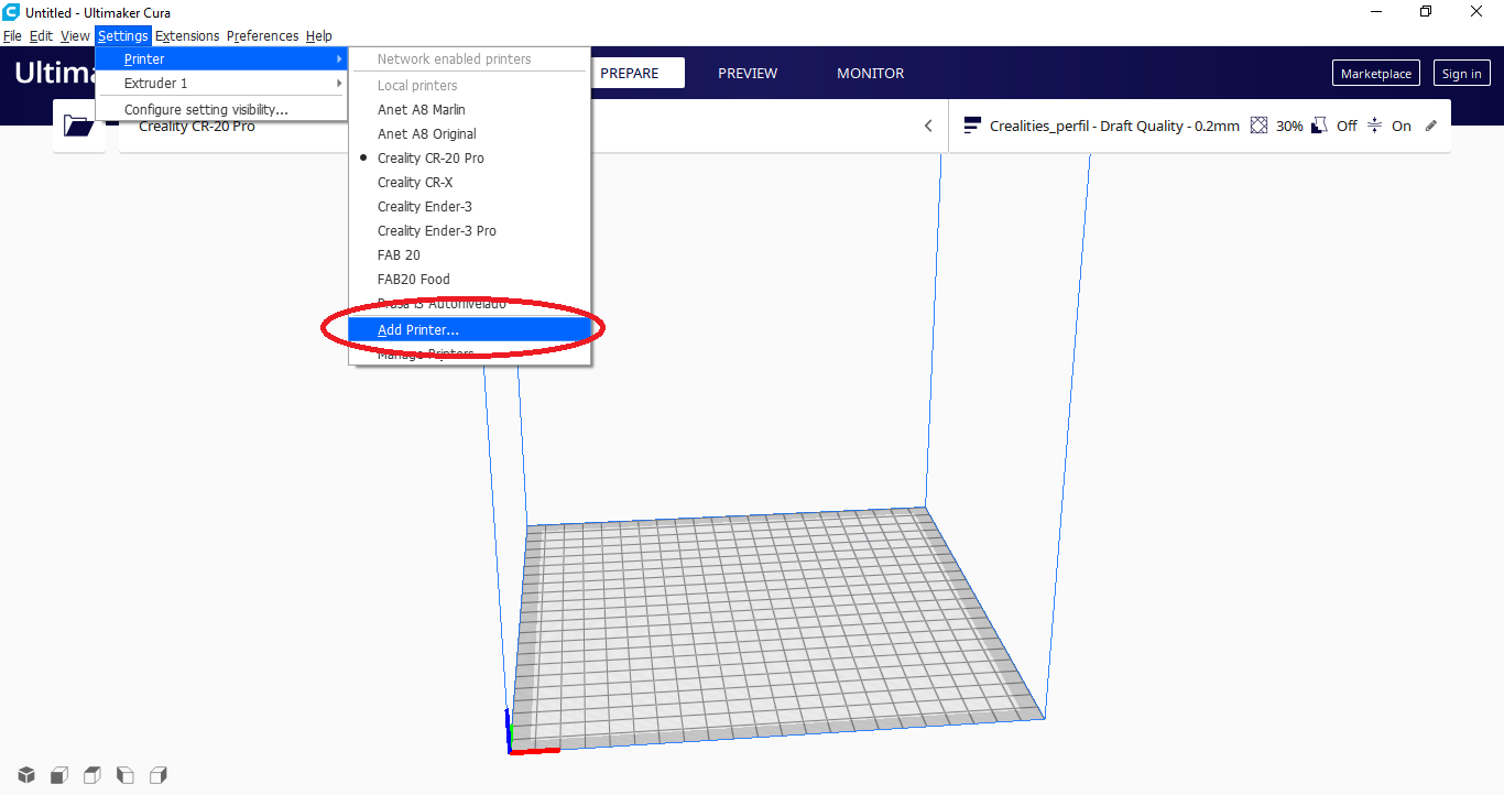
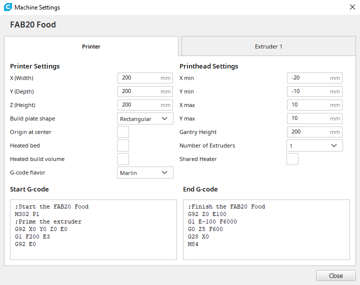
To define a new printer and configure it for the FAB 20, choose Settings > Printers > Add Printers
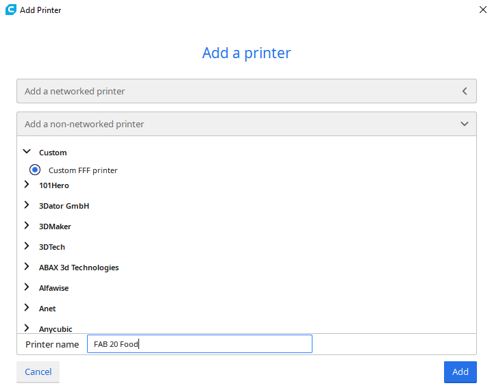
Let’s choose a generic printer, type FFF (Fused Filament Fabrication), and name it as FAB 20
We configure the following parameters referred to the 3D printer FAB 20:
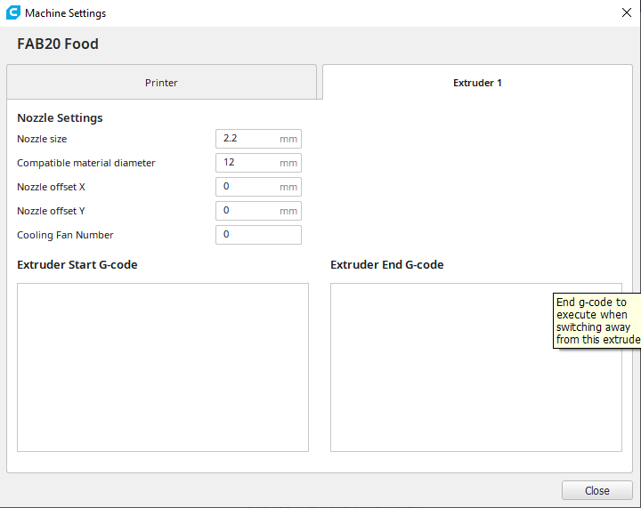
These are the Extruder data for the FAB 20:
Now we will configure the printing parameters
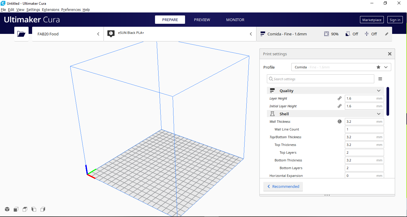
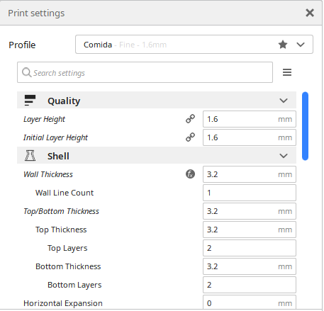
Now we will configure the printing parameters, such as QUALITY and SHELL, with the following values:
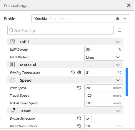
Now we will configure the printing parameters, such as INFILL, MATERIAL and SPEED, with the following values:
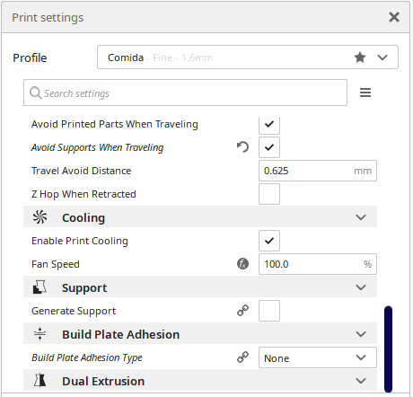
Finally we will configure the printing parameters, such as COOL, SUPPORT and BUILD PLATE ADHESION, with the following values:
Hand Control FAB 20
When we need to position the extruder in position 0,0,0 we need to move the axes in several units, the menu on the FAB 20 screen can do it, but it is very time consuming since the menu is optimized to control a printing.
Therefore, I designed a manual control for the printer. This control will allow you to directly modify the monitoring of the 3 axes, in addition to choosing the movement speeds.
A card will be designed with the Attiny44A microcontroller, which will send GCODE commands to the printer in the respective axes.
G91 command: It is to tell the printer to place it in relative movement mode, that is to say that the movement that we send will be carried out taking the current point as the starting point.
G1 command: It is to send a movement in the X, Y and Z axes, in addition to its speed.
For example
    G91
    G1 F1500 Z1.0
It is the order of a relative movement in the Z axis of 1.0 millimeters with a speed of 1500 millimeters per minute
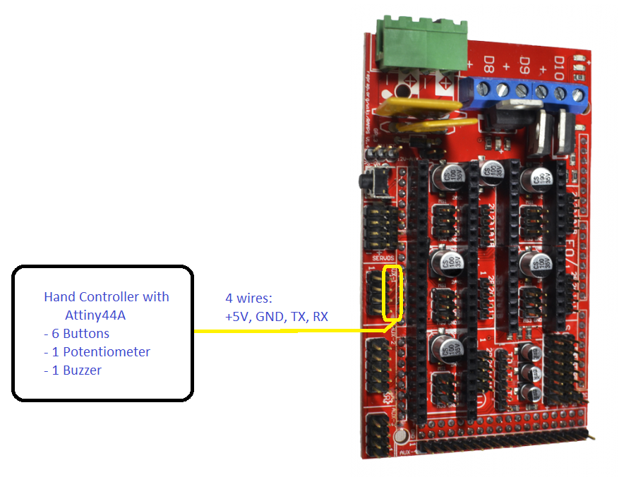
These axis movement commands will be sent through the serial port, in the case of the Attiny44A through a software generated port and in the case of the printer through the serial port 0 of the Arduino Mega, as shown in the picture.
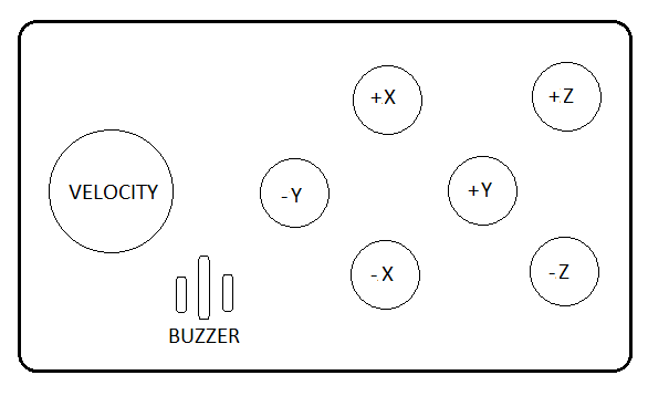
We detail the parts that the hand control will have in the following image:
Electronic Designing
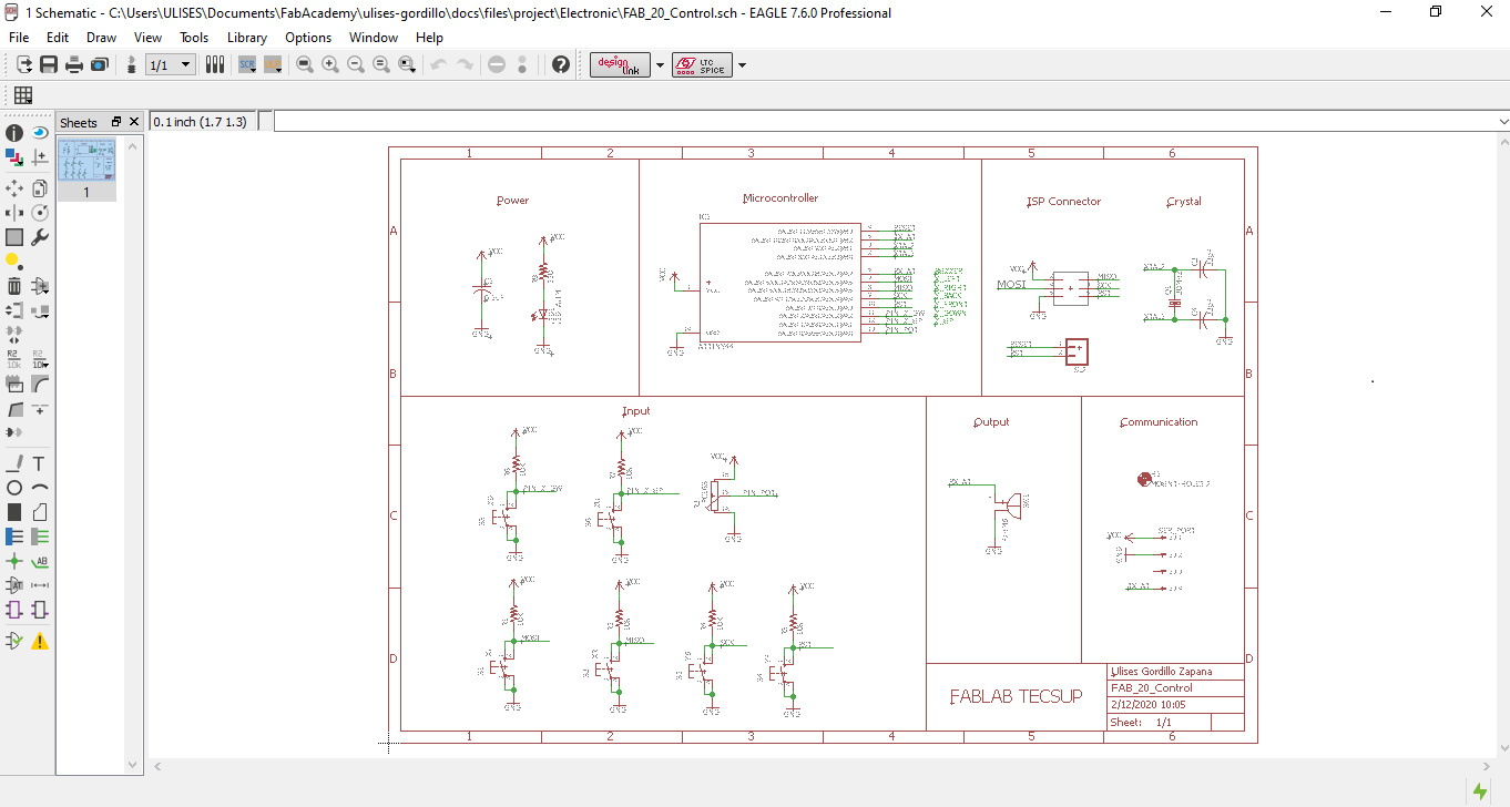
For the design of the printed circuit board, the Autodesk Eagle program was used, incorporating 6 buttons, 2 for each axis of movement, 1 potentiometer to configure the movement speed and 1 buzzer to confirm the movement actions.We have the following circuit:
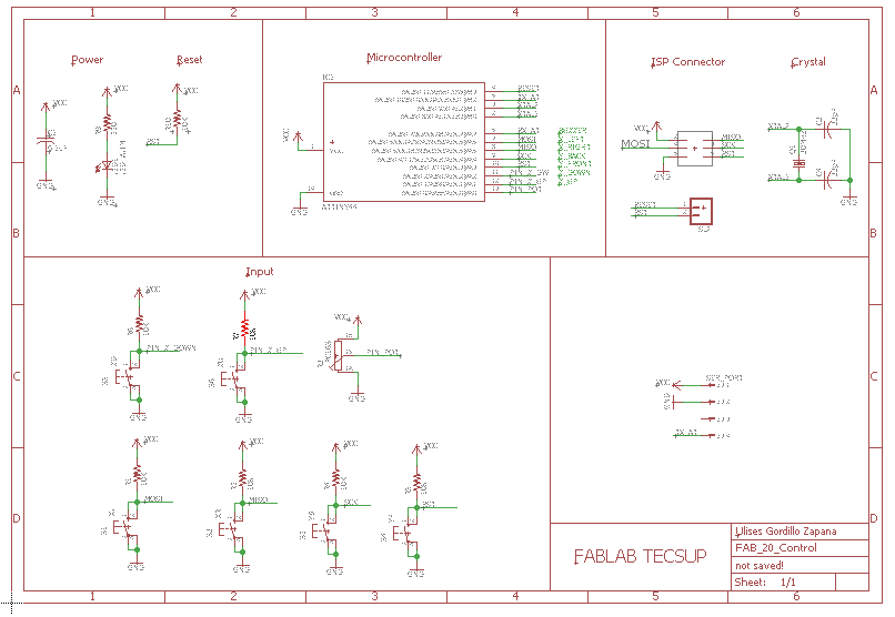
This would be the circuit in Autodesk Eagle:
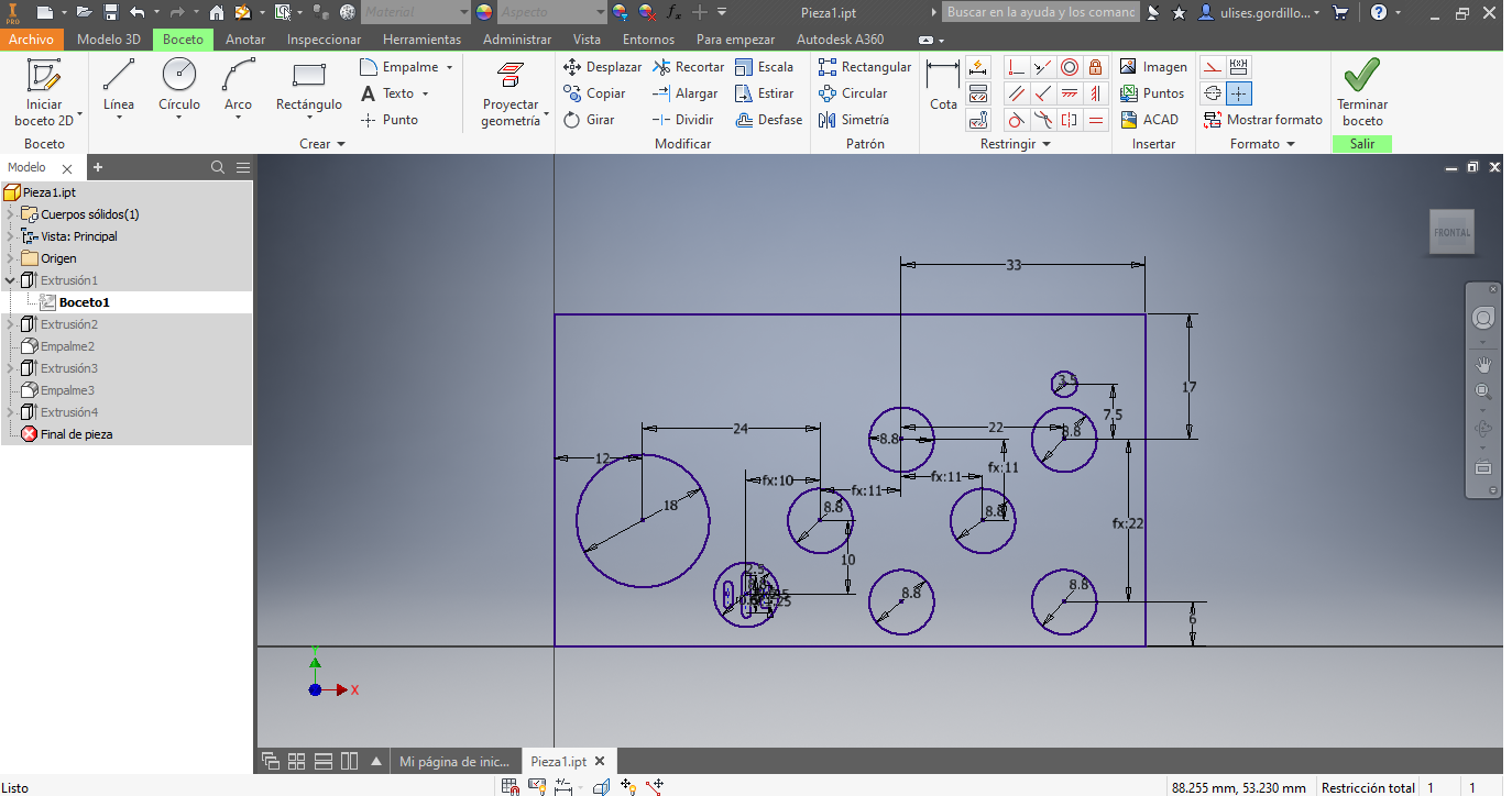
Begin to locate the components according to the connections or obtaining the track as short as possible, in addition to locating them as reduced as possible.
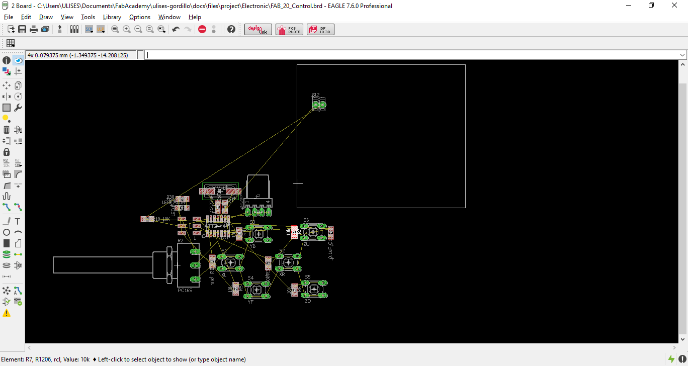
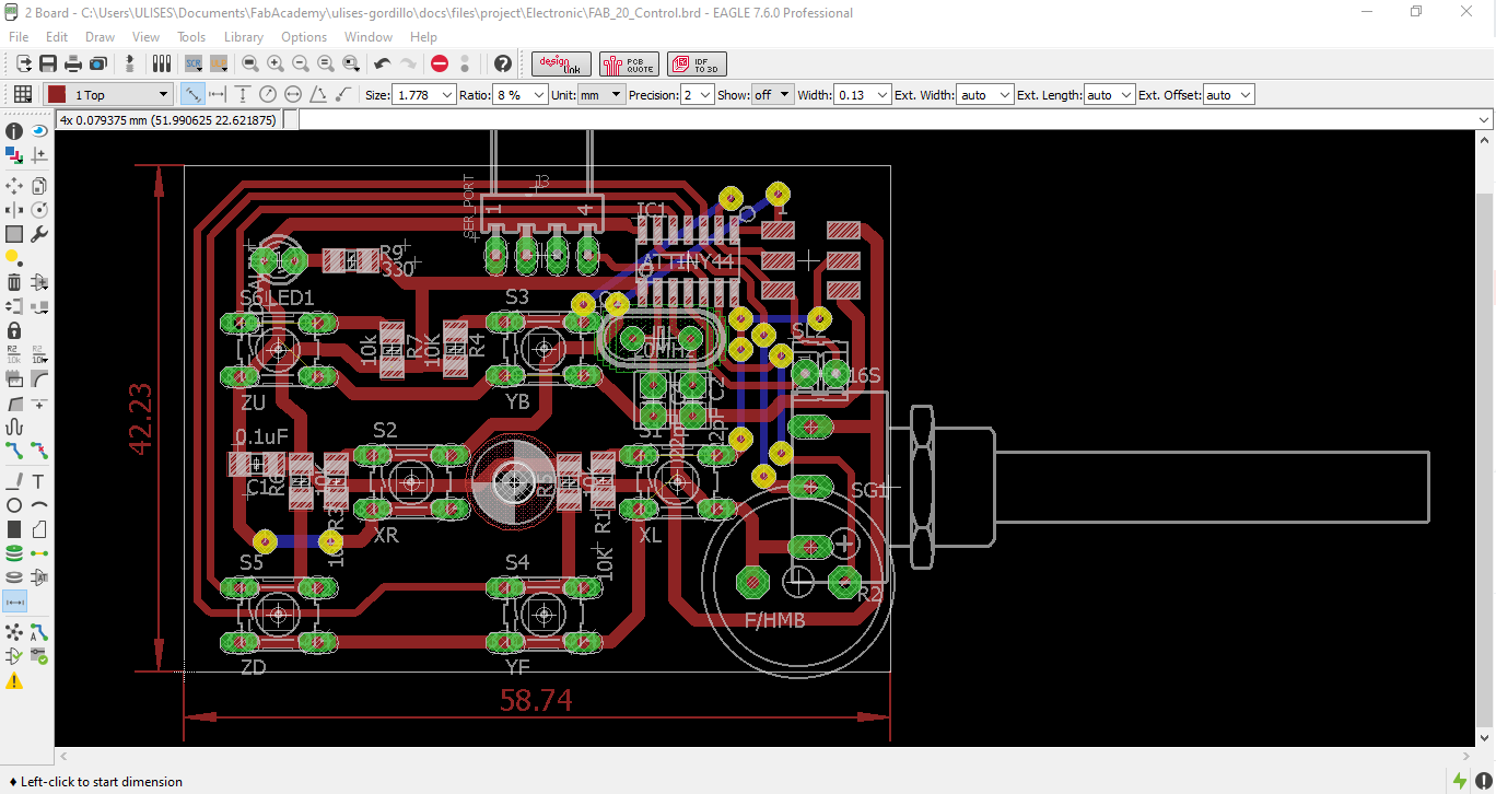
After placing them in the most optimal position, as in the image, we begin to place the tracks.
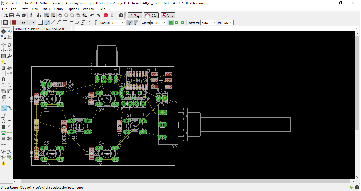
We can see the wiring proccess in the video:
The design ended like this:
Manufacturing the board
To manufacture the electronic card, we will use a GCODE generator made by third parties for Autodesk Eagle, called PCB Gcode.
To use it I have to download it from the tools search on the Autodesk Eagle page and copy them to the ULP folder of the Autodesl Eagle installation.
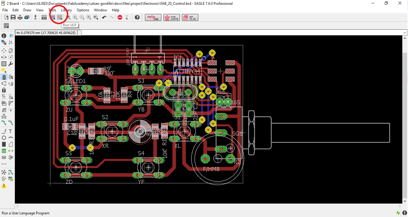
We start the GCODE PCB tool from the Run ULP icon:
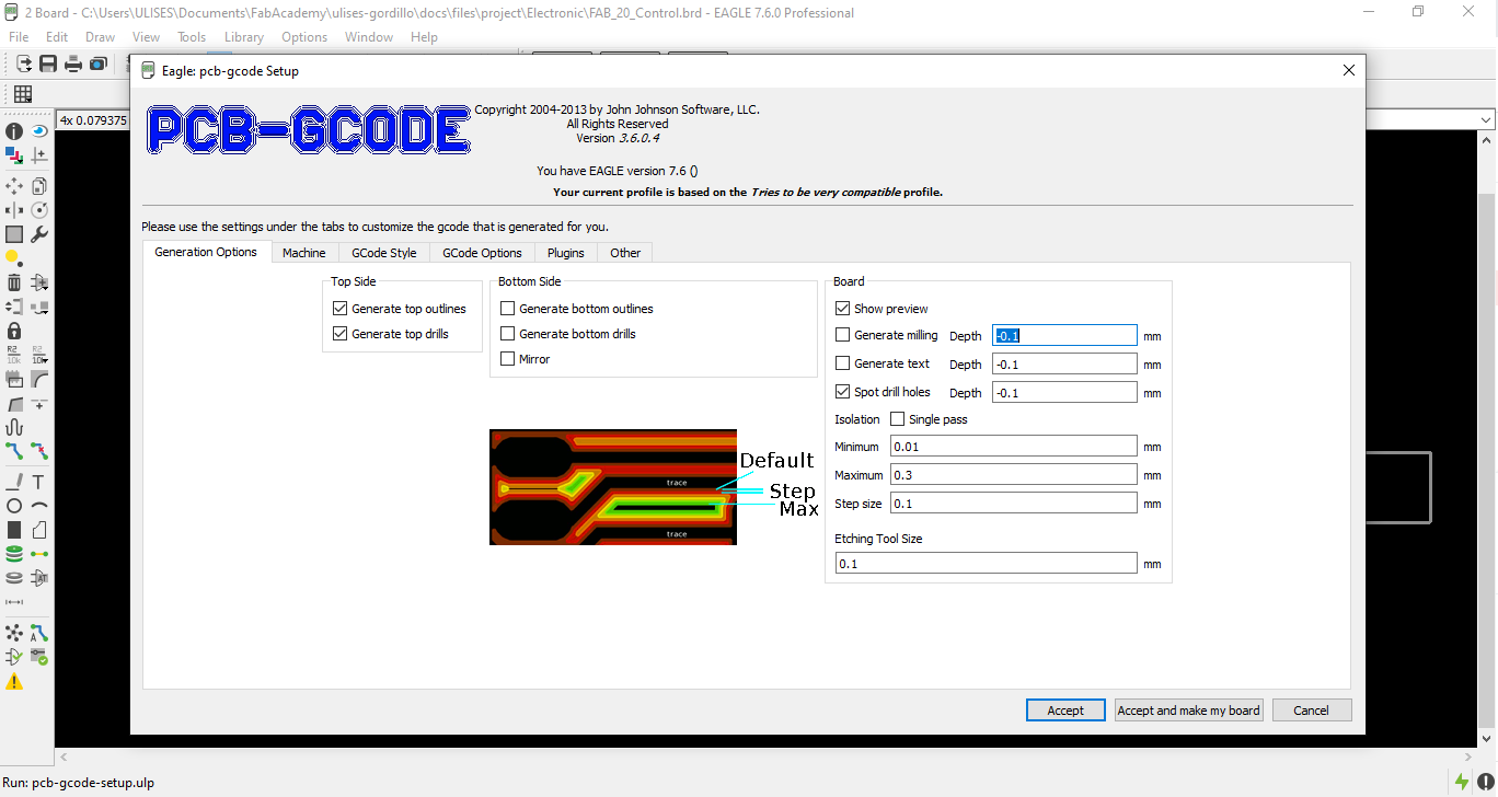
We configure the gcode file generation options:
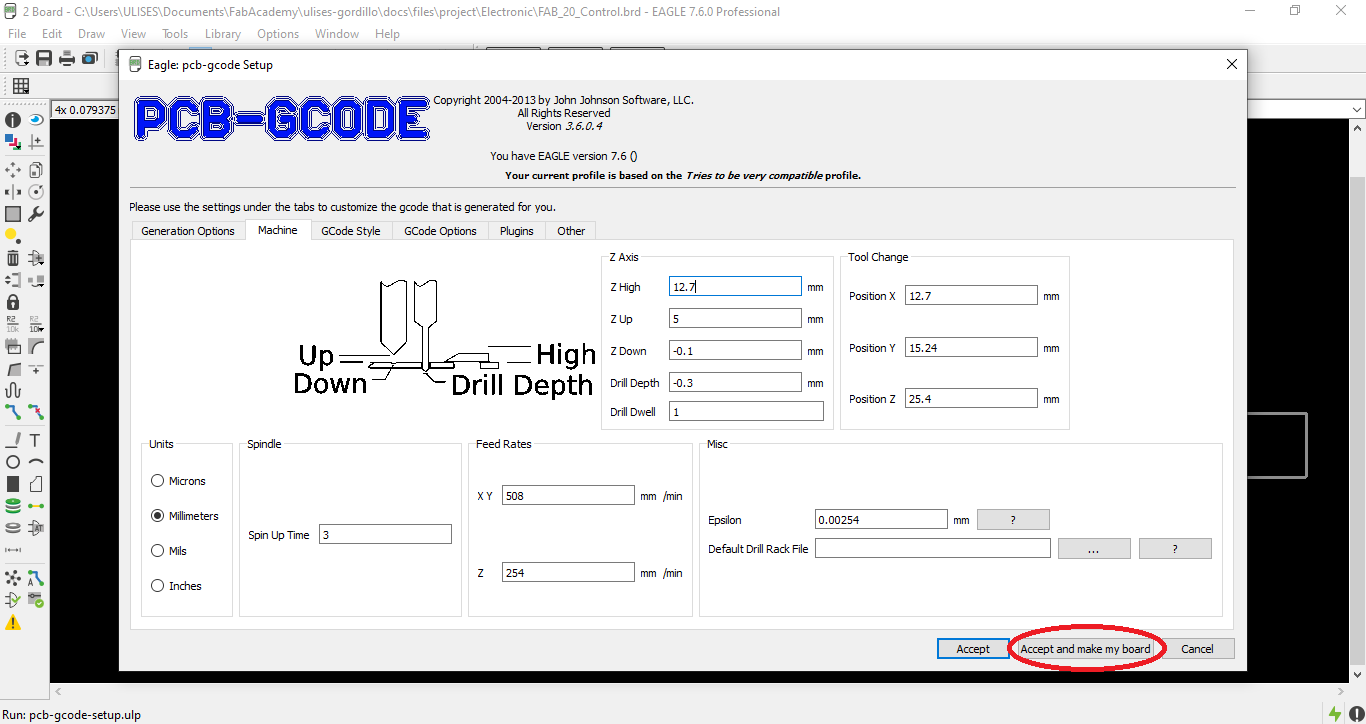
We configure the machine options:
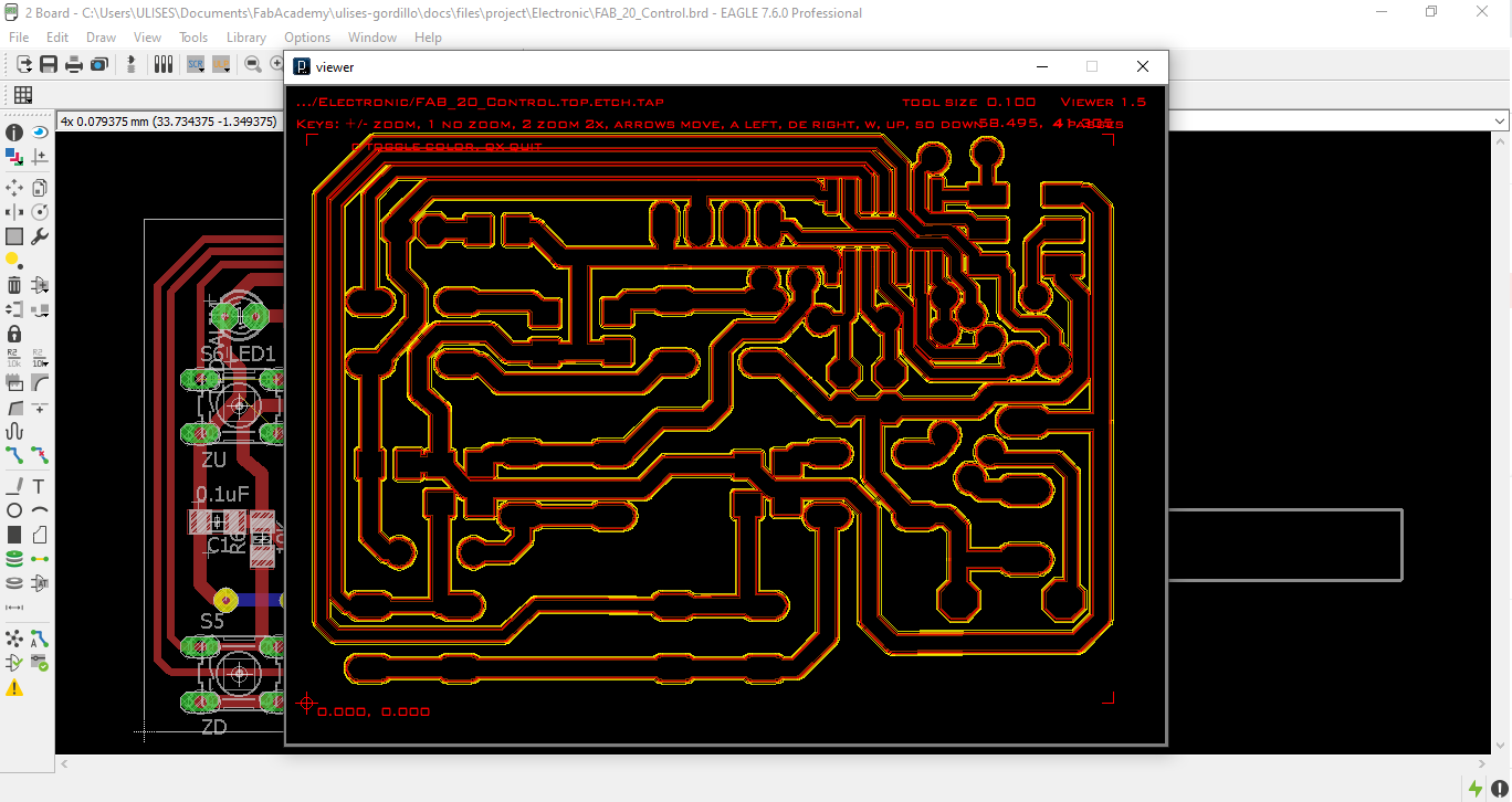
Here we can see the process of generating GCODE
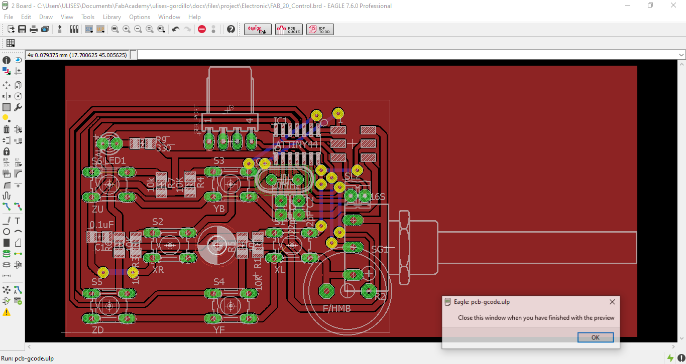
This would be the preview of the GCODE milling process
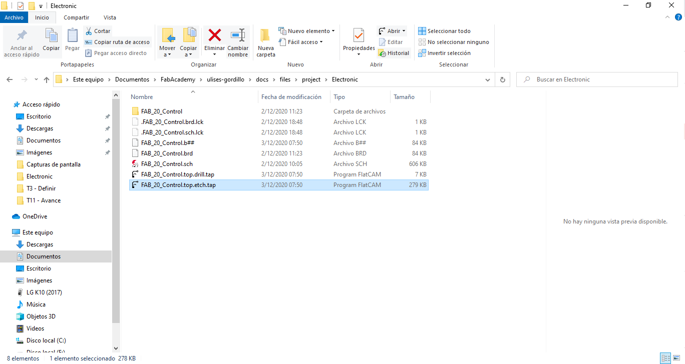
In the file folder a GCODE file with the extension of TAP was generated
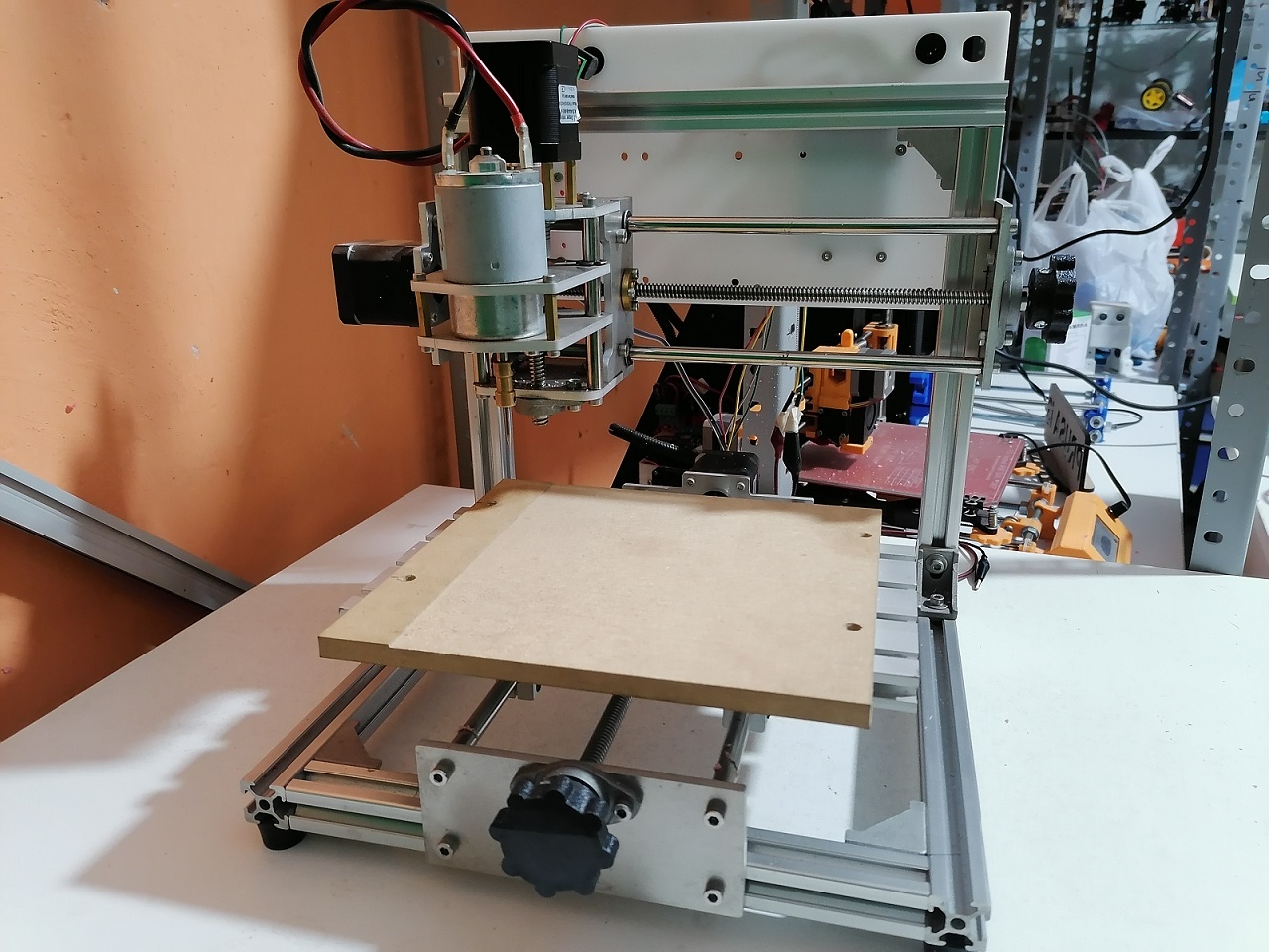
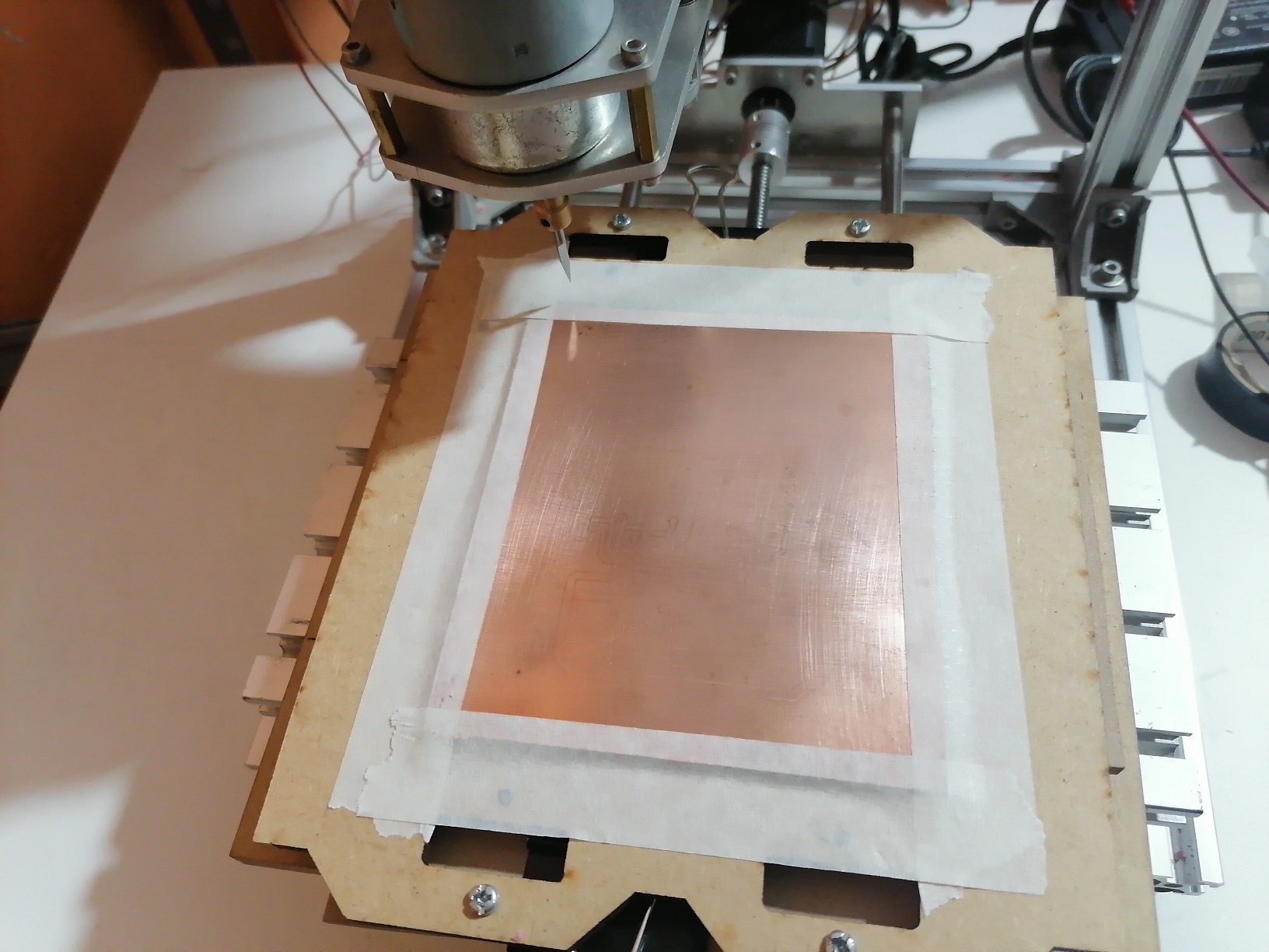
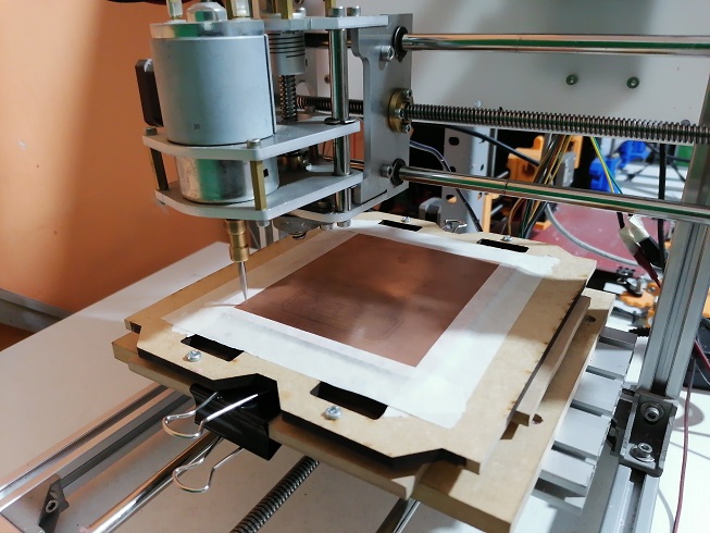
For the manufacturing we will use a CNC based on the Arduino Board, the CNC shield and the GRBL firmware, which will interpret the GCODE:
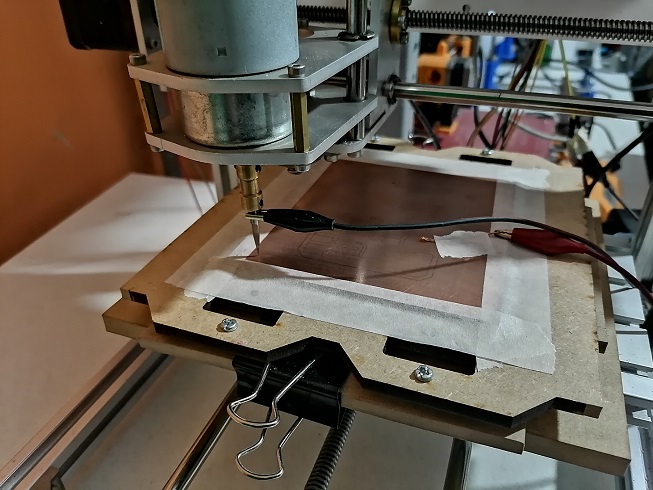
We place the initial material of the copper plate for manufacturing.
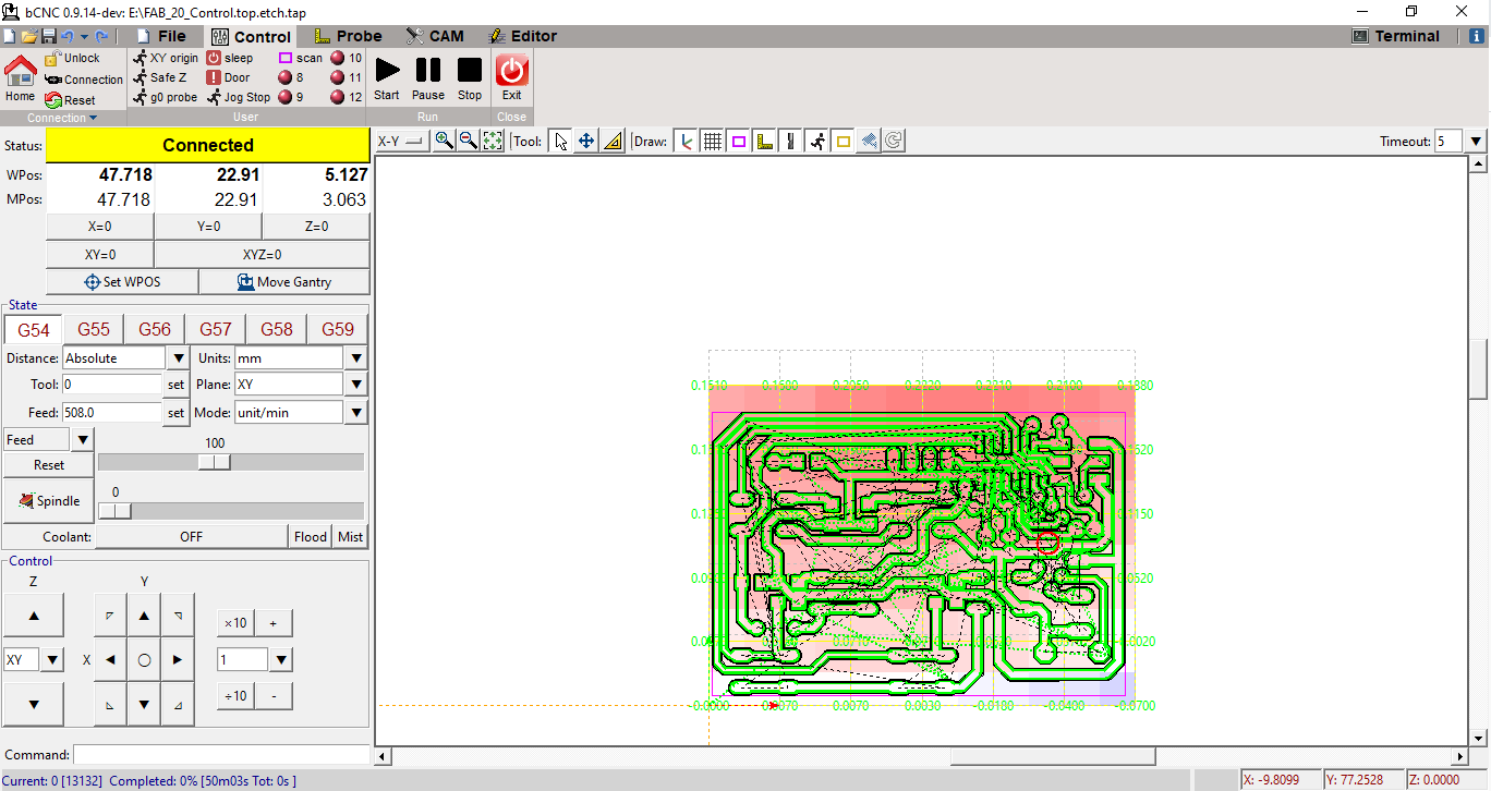
We will use bCNC software for milling:
This is the open view software interface:
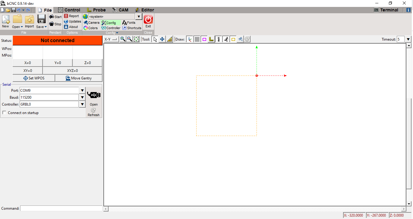
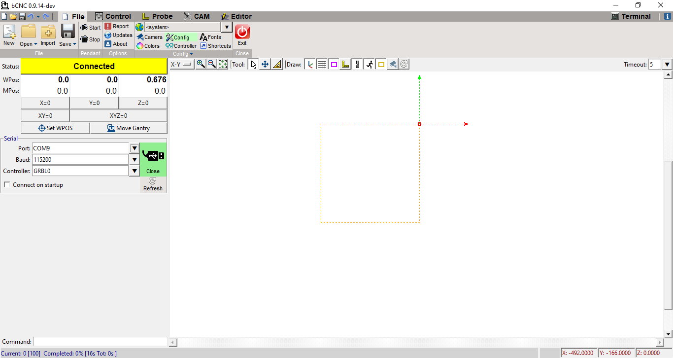
We choose the COM9 serial port and the 115200 baud rate and press the OPEN button to start the connection with the CNC:
For the leveling of 0 in the Z axis we will use the PROBE routine to achieve exactly having the cutter at the height of the copper:
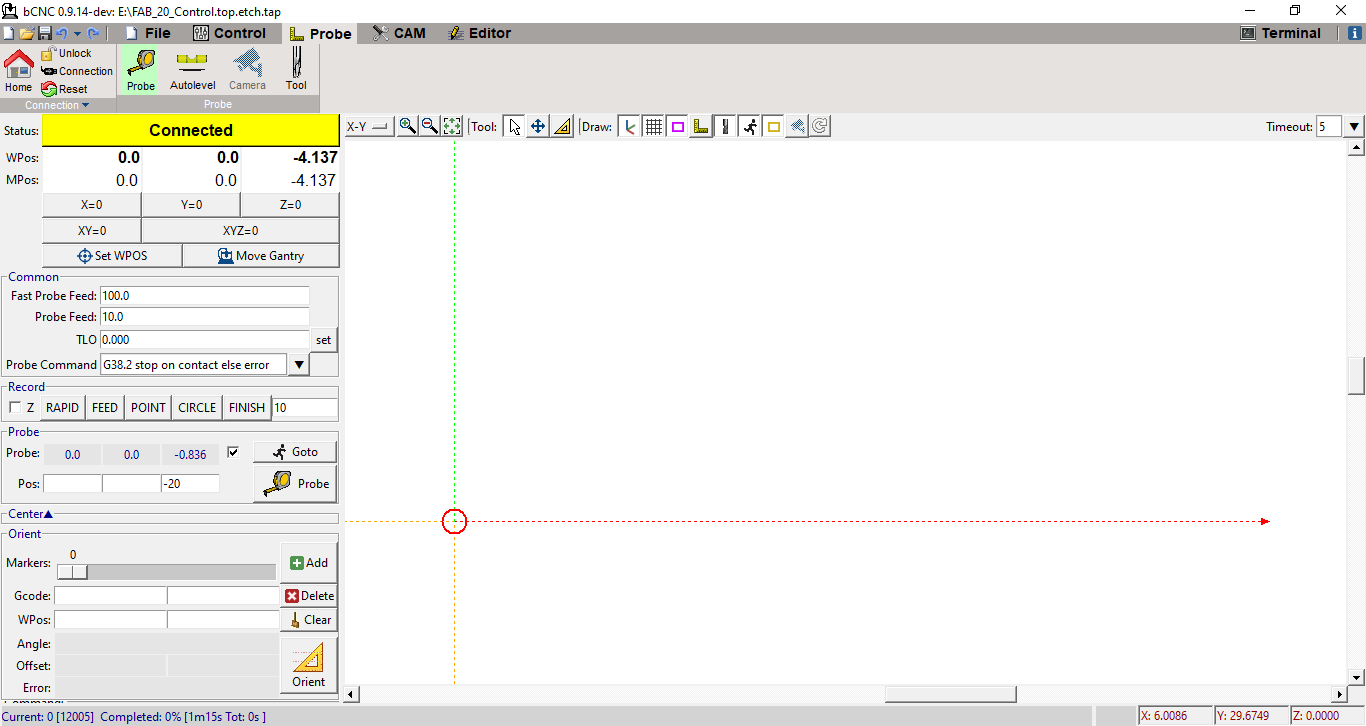
This would be the starting point or reference point of the works:
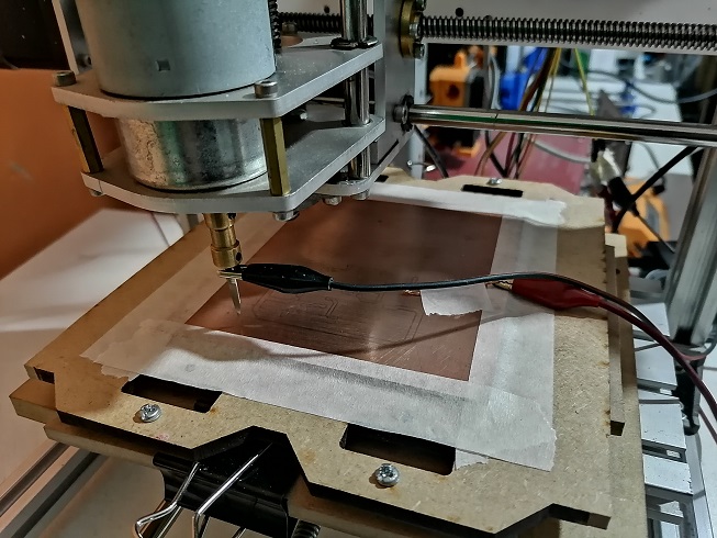
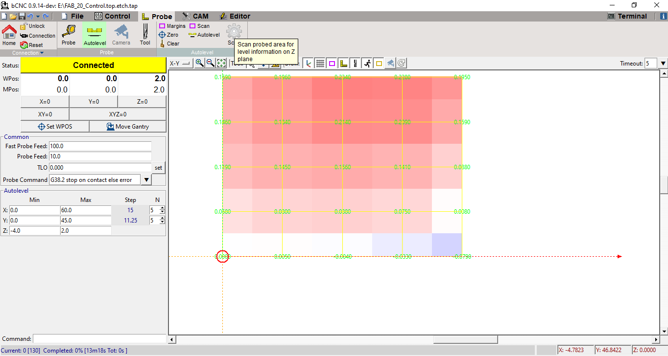
Now we will use the AUTOLEVEL routine to find the level of the entire work area but as a mesh for the correction of the height to be milled with the movement of the Z axis
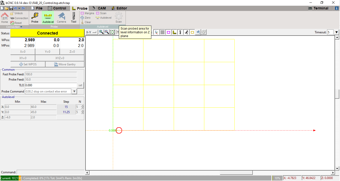
We can see the AUTOLEVEL routine:
This would be the result of the AUTOLEVEL routine:
We have to save the AUTOLEVEL values as a file with a PROBE extension:
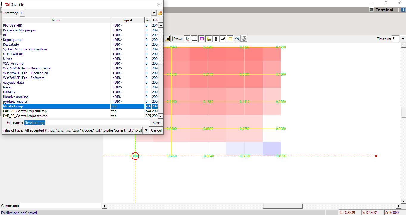
After saving the file we must load our GCODE file to work:
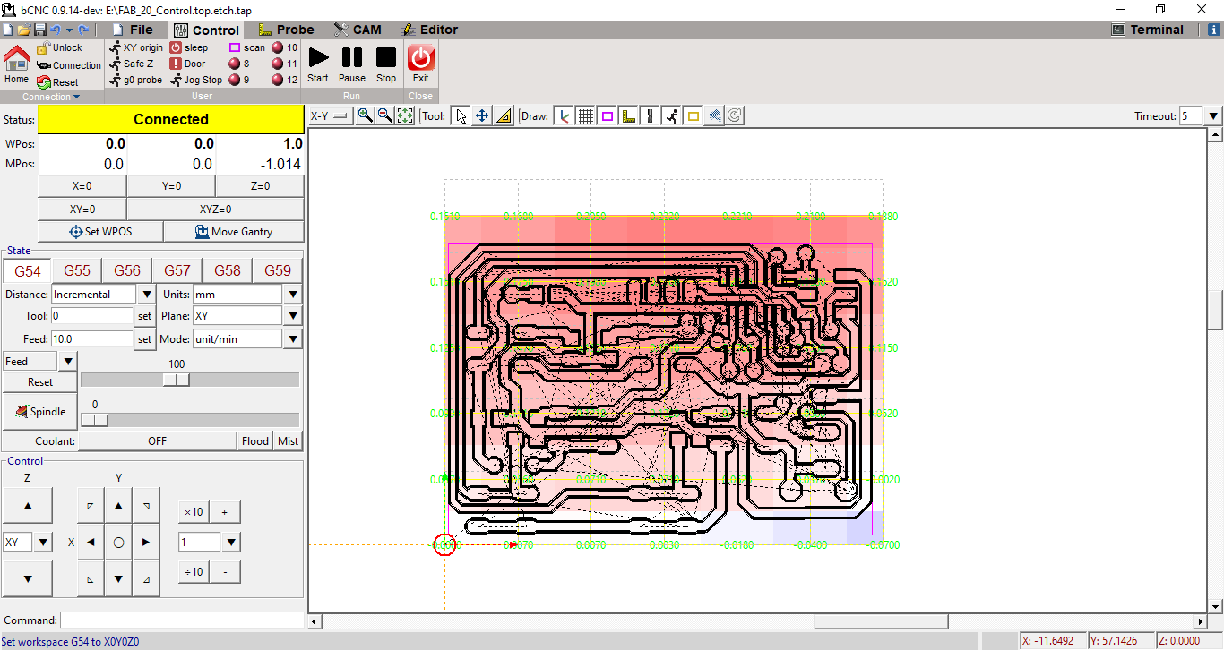
We place the starting point and we can start the track milling process:
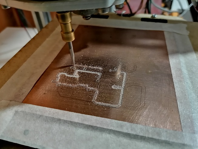
The milling process began, in the bCNC software we can monitor how progress is developing:
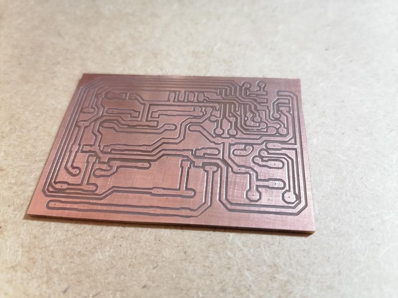
In copper plate it would be advancing as shown in the image:
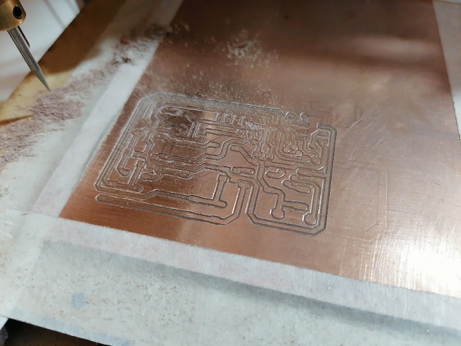
After finishing we have the milled plate with the tracks:
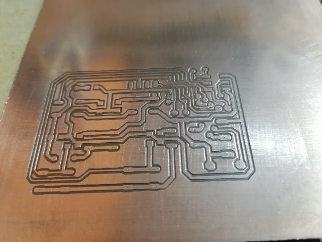
After cleaning we have the with a good finish:
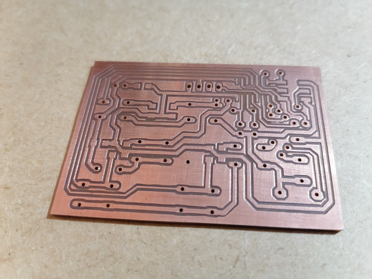
Then we cut the outline of the design, in my case I used a simple saw that I have:
Later we drill the holes of the PCB, and finally this would be our PCB board:
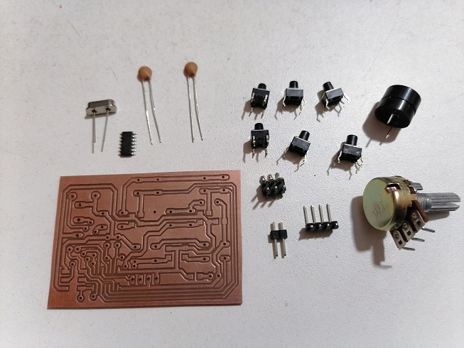
Assembling the Board
For the assembly we have all the components:
We start by soldering the SMDs, like the Attiny44A microcontroller:
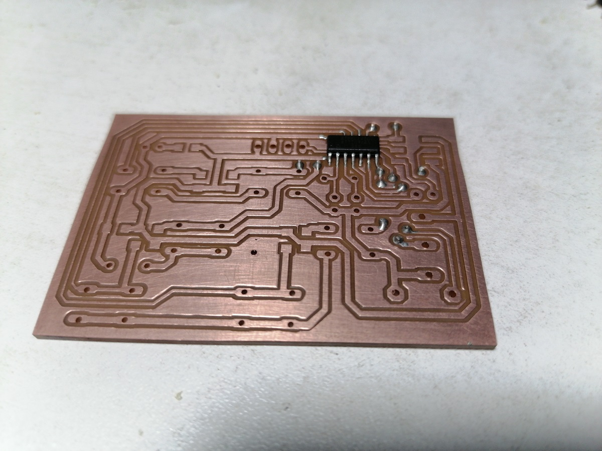
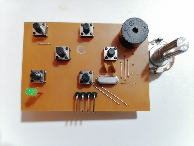
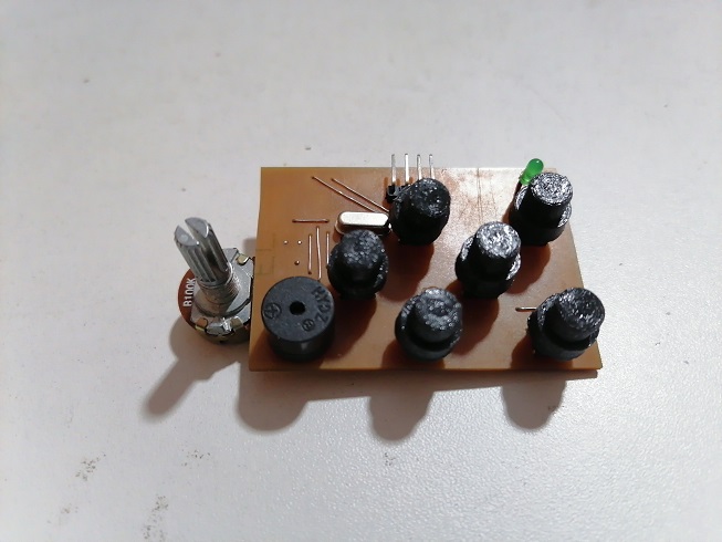
Then the rest of the components, on the top part, would remain in the image:
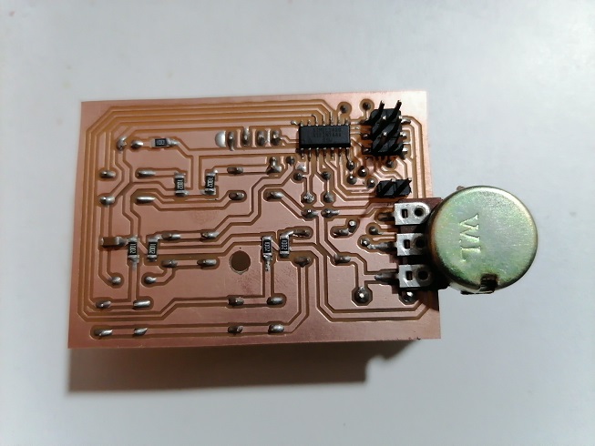
And in the part of the botton we would have like this:
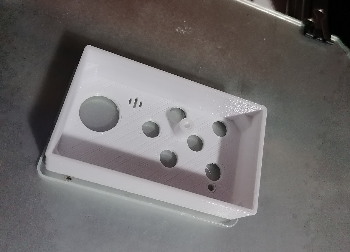
Now we will work on the box for the hand control:
We add the walls of the box:
This would be the basis of the finished box:
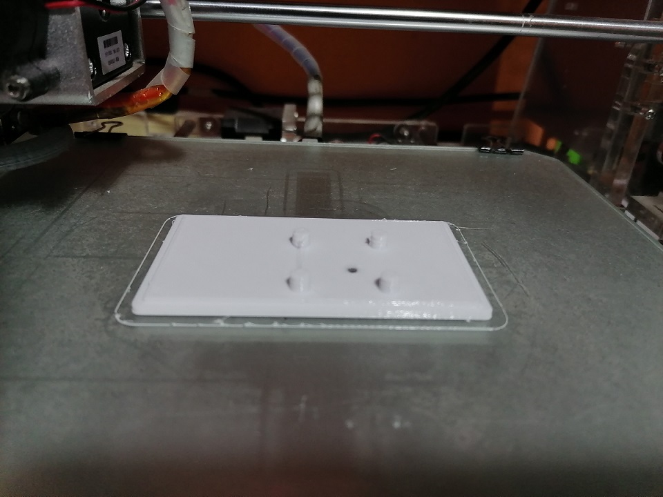
We also design the lid of the base of the box:
This would be the cover of the base:
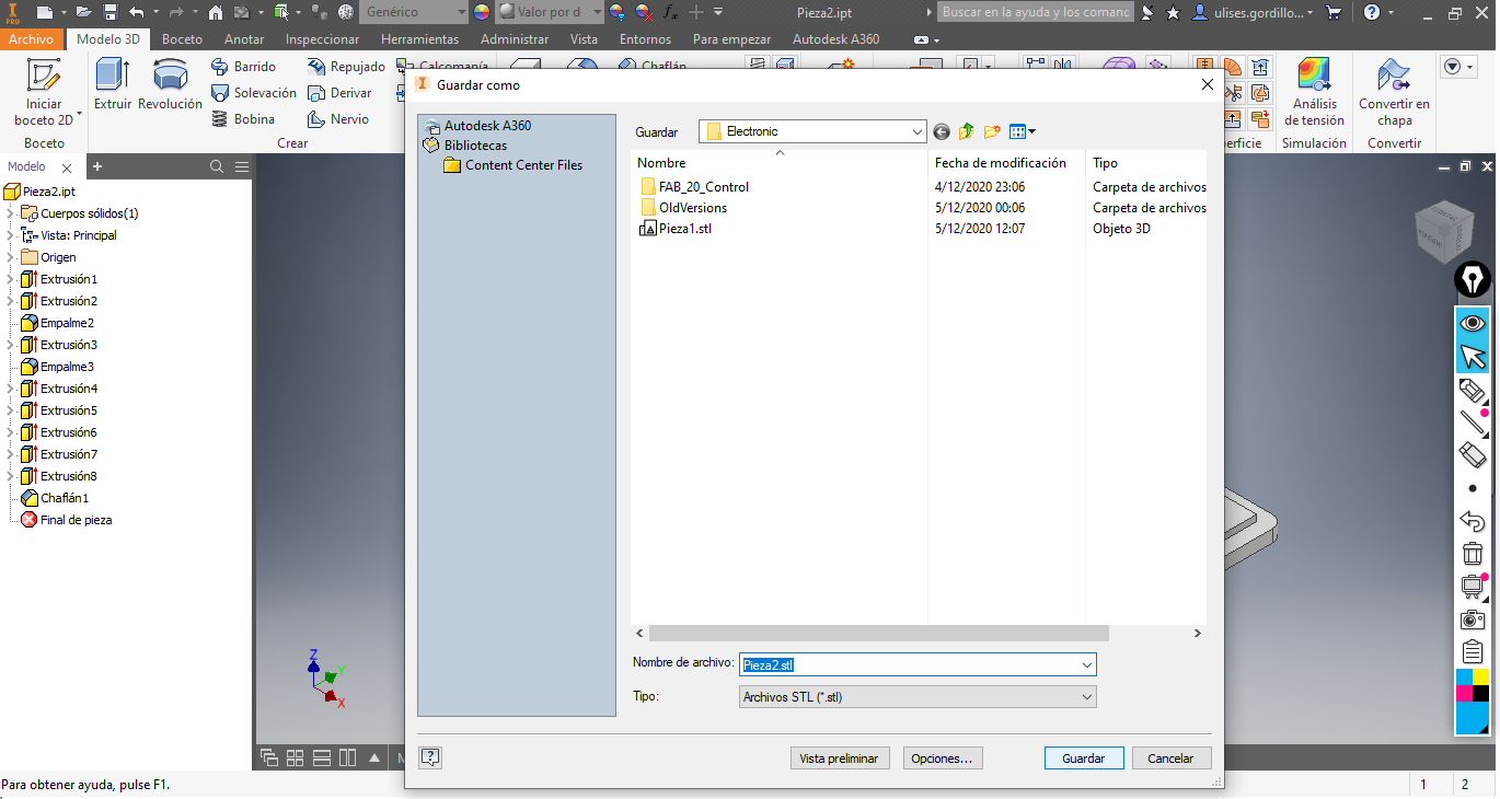
We export the STL files for printing on a 3D printer:
We save these files as STL files:
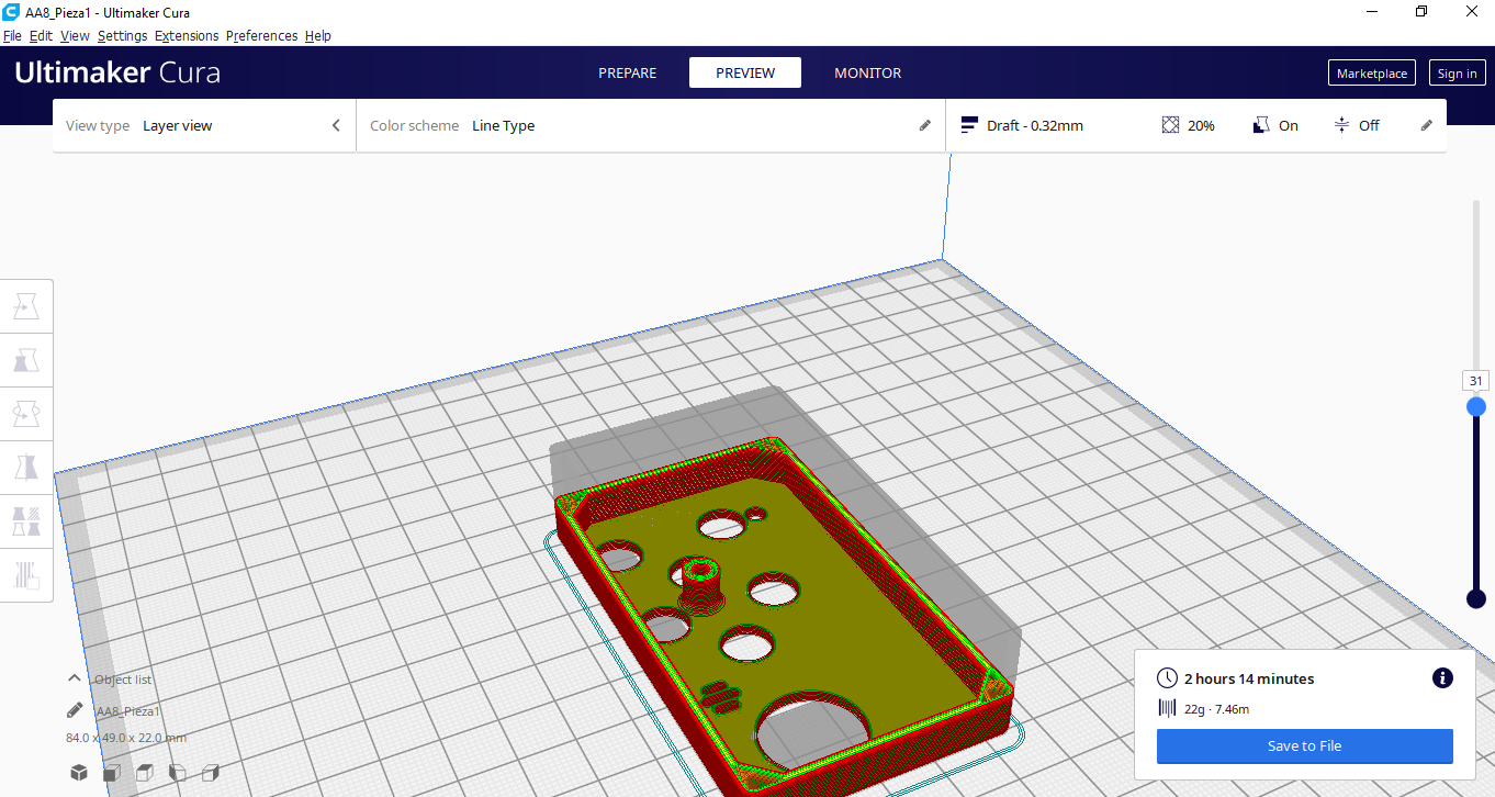
We load the database file in the CURA slicer and generate the GCODE file:
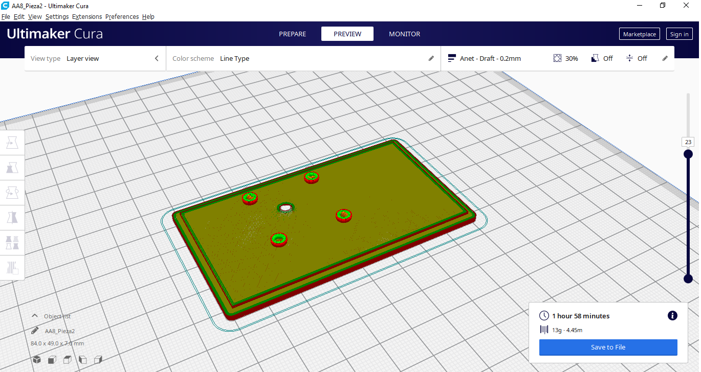
In the same way we do with the base cover:
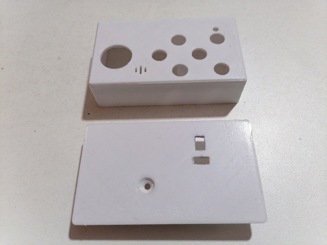
Here we see making the base of the box:
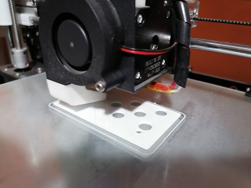
Here we have the base of the box finished printing
Here we have the cover of the box finished printing
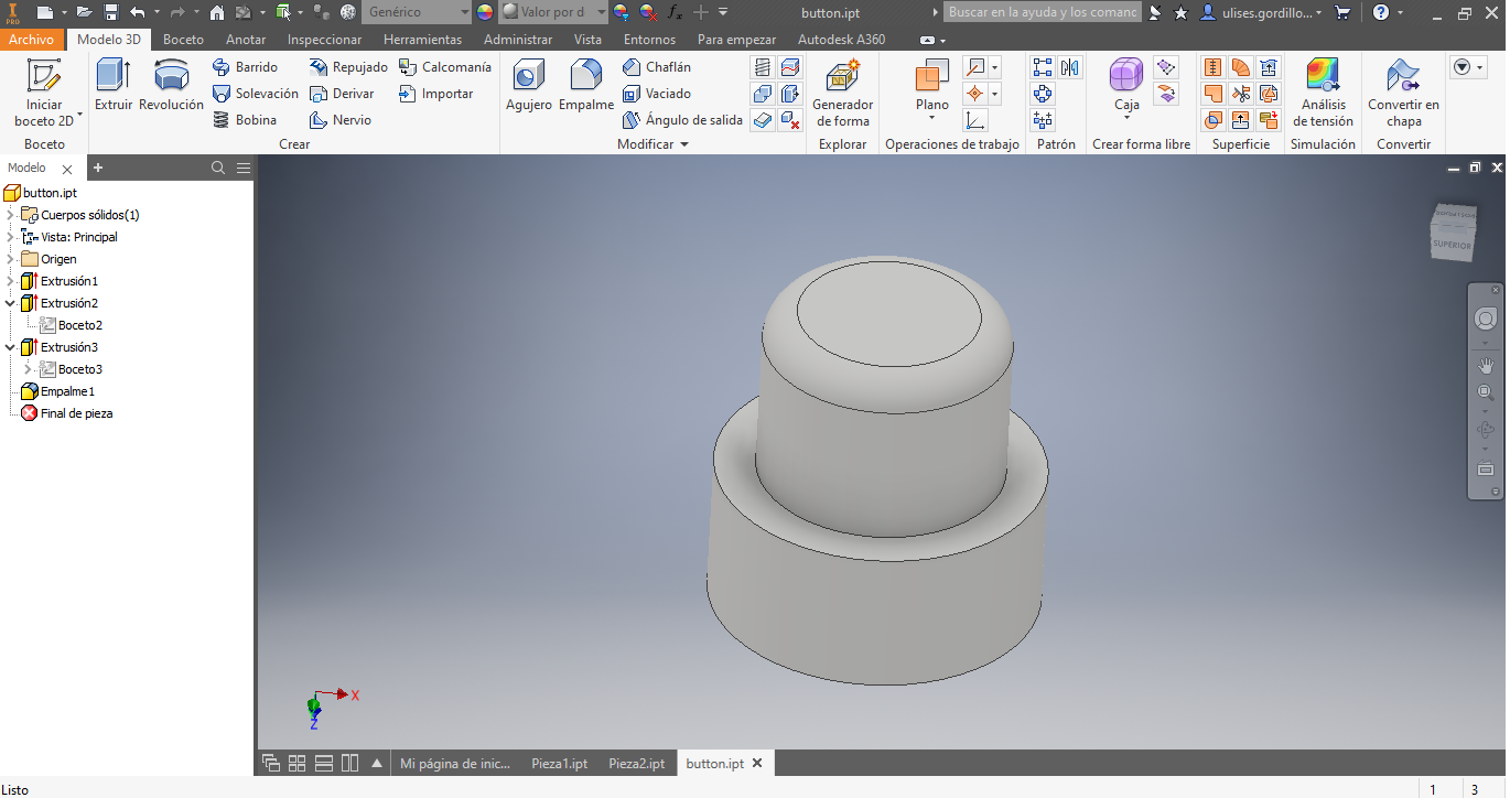
Now we design the buttons 3D for the push buttons:
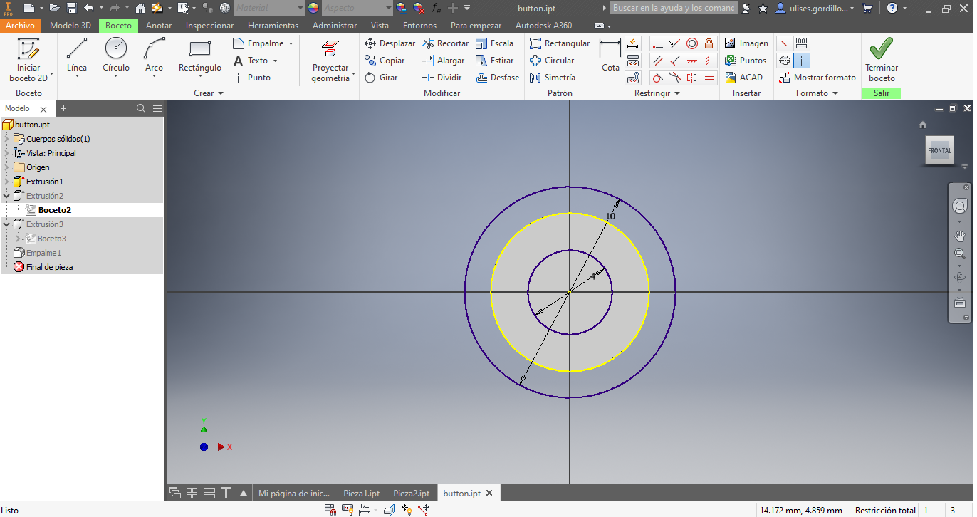
These would be the buttons, we would have to make 6 units of them:
We load in the slicer CURA to generate the GCODE file:
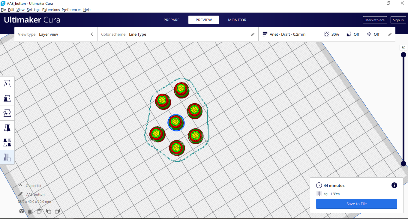
Here we would have the printed buttons:
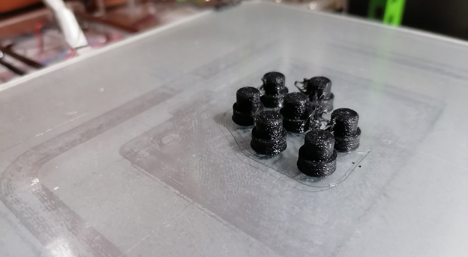
Here we would have the printed buttons ready for the assembly process:
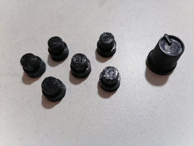
Here we have the base of the box and the lid of the box ready for its assembly process
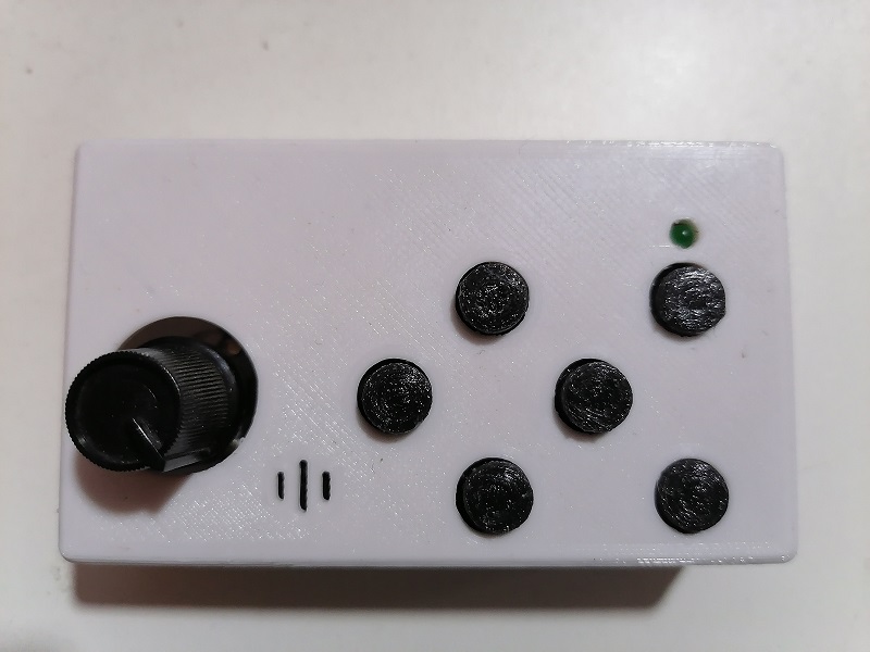
We start by placing the buttons at the top of the pushbuttons of the electronic card:
After placing the electronic card inside the box, and placing the lid on it, we have the finished assembly:
Programming the Board
To program the hand control, we carry out the program in Arduino IDE, so that when a button is pressed, a message is sent through the serial port with the following structure:
    G91
    G1 F[Analog Value] [Axis][Lenght]
This would be the commands to implement:
| Description | Command |
|---|---|
| +X Movement | G1 Fxxxx X0.1 |
| -X Movement | G1 Fxxxx X-0.1 |
| +Y Movement | G1 Fxxxx Y0.1 |
| -Y Movement | G1 Fxxxx Y-0.1 |
| +Z Movement | G1 Fxxxx Z0.1 |
| -Z Movement | G1 Fxxxx Z-0.1 |
The program would be as shown:
//****************************************************
// Ulises Gordillo Zapana - FabAcademy 2020
//****************************************************
#define pin_tx      8
#define pin_buz     7
#define pin_x_left  6
#define pin_x_right 5
#define pin_y_back  4
#define pin_y_front 3
#define pin_z_down  2
#define pin_z_up    1
#define pin_pot     0

// Include Resource
#include <SoftwareSerial.h>
SoftwareSerial SerialPort(pin_buz, pin_tx); // RX, TX

int dato_serial=0;
#define   estado_z_up     1
#define   estado_z_down   2
#define   estado_y_front  3
#define   estado_y_back   4
#define   estado_x_right  5
#define   estado_x_left   6
#define   estado_reposo   7
byte estado = estado_reposo;
// Function SETUP
void setup() {
  SerialPort.begin(115200);
  pinMode(pin_buz,OUTPUT);
  digitalWrite(pin_buz,LOW);
  pinMode(pin_x_left,INPUT);
  pinMode(pin_x_right,INPUT);
  pinMode(pin_y_back,INPUT);
  pinMode(pin_y_front,INPUT);
  pinMode(pin_z_down,INPUT);
  pinMode(pin_z_up,INPUT);
}

// Function LOOP
void loop(){
  if (!digitalRead(pin_z_up)){    estado = estado_z_up;}
  if (!digitalRead(pin_z_down)){  estado = estado_z_down;}
  if (!digitalRead(pin_y_front)){ estado = estado_y_front;}
  if (!digitalRead(pin_y_back)){  estado = estado_y_back;}
  if (!digitalRead(pin_x_right)){ estado = estado_x_right;}
  if (!digitalRead(pin_x_left)){  estado = estado_x_left;}
  if (estado != estado_reposo){
    SerialPort.println("G91");
    SerialPort.print("G1 F");
    SerialPort.print(analogRead(A0));
    SerialPort.print(" ");
    switch (estado){
      case estado_z_up:     SerialPort.println("Z0.1");   break;
      case estado_z_down:   SerialPort.println("Z-0.1");   break;
      case estado_y_front:  SerialPort.println("Y0.1");   break;
      case estado_y_back:   SerialPort.println("Y-0.1");   break;
      case estado_x_right:  SerialPort.println("X0.1");   break;
      case estado_x_left:   SerialPort.println("X-0.1");   break;
    }
    digitalWrite(pin_buz,HIGH);
    delay(100);
    digitalWrite(pin_buz,LOW);
    estado = estado_reposo;
  }
}
The connection of the electronic card for its programming:
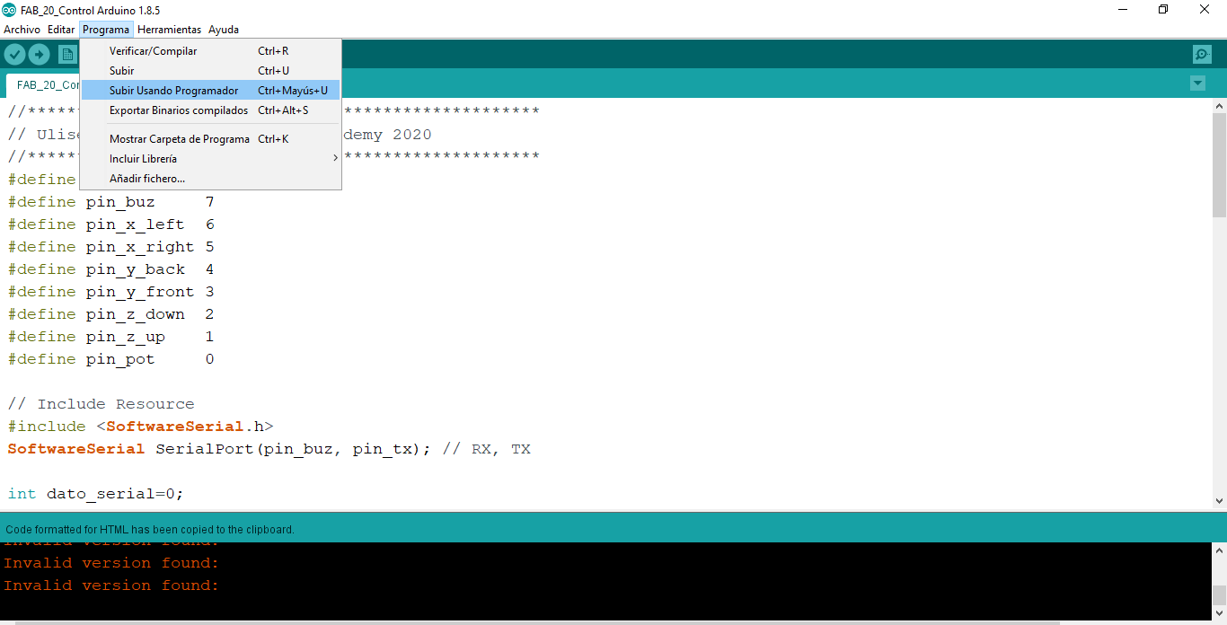
Configure the Arduino IDE to compile the program for the Attiny44A
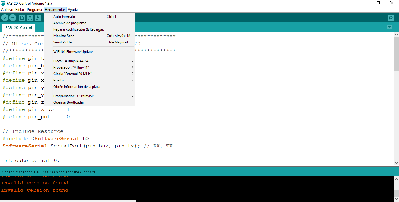
Compile and use the Arduino IDE to load the hex file into the Attiny44A microcontroller.
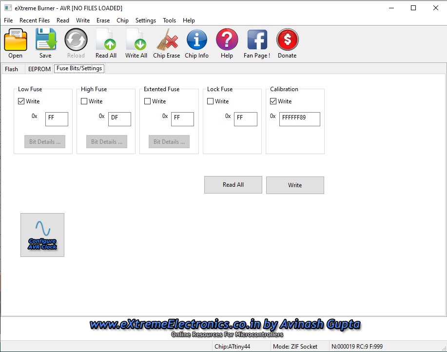
To configure the microcontroller configuration bit fuses for a 20MHz crystal, record with the following combination.This recording is done with the USBASP recorder and the eXtreme Burner software.
Testing the Hand Control FAB 20
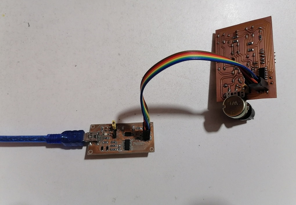
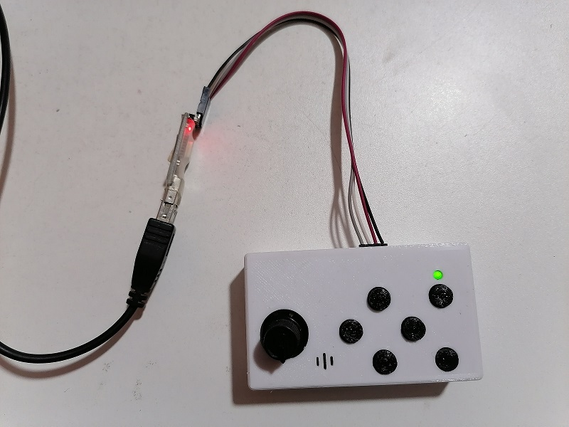
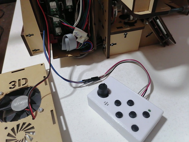
The first part of the test is to connect the electronic card connected to a USB to UART or serial communication converter, so that we can see the commands sent by the hand control to the computer:
Here we have the electronic card connected to the
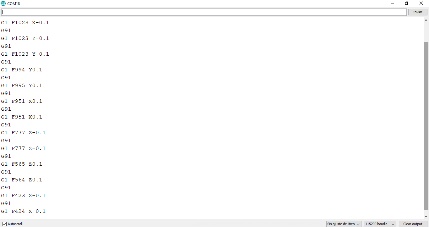
We open the Arduino interface and open the Seria Monitor linked to the serial port of the converter, which in my case is COM18, we can see the following commands sent every time I press a button:
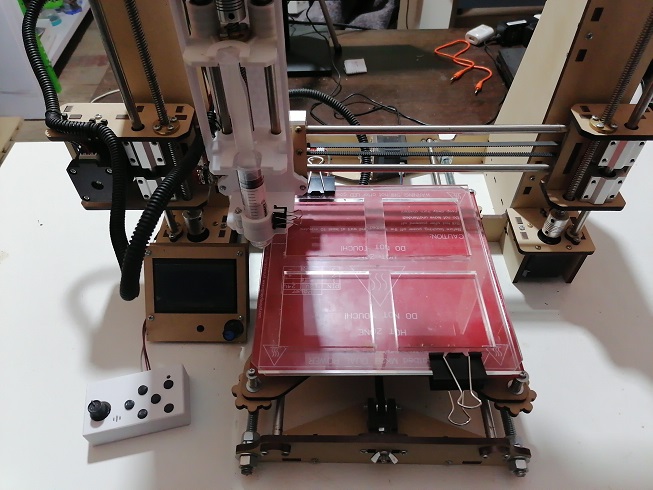
Now that we have it working, we connect it to the Ramps 1.4 card so that it connects to Serial Port 0 of the Arduino:
Here we have the hand control connected to the FAB 20 3D printer
For the operation we have the following demonstration video:
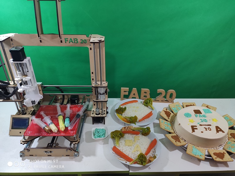
Testing FAB 20
This part will contemplate performing functional tests with different food samples such as chocolate delicacy, mashed potatoes and whipped cream for cakes.
First, let’s see the designs that we will make, according to the FABACADEMY 2020 course:
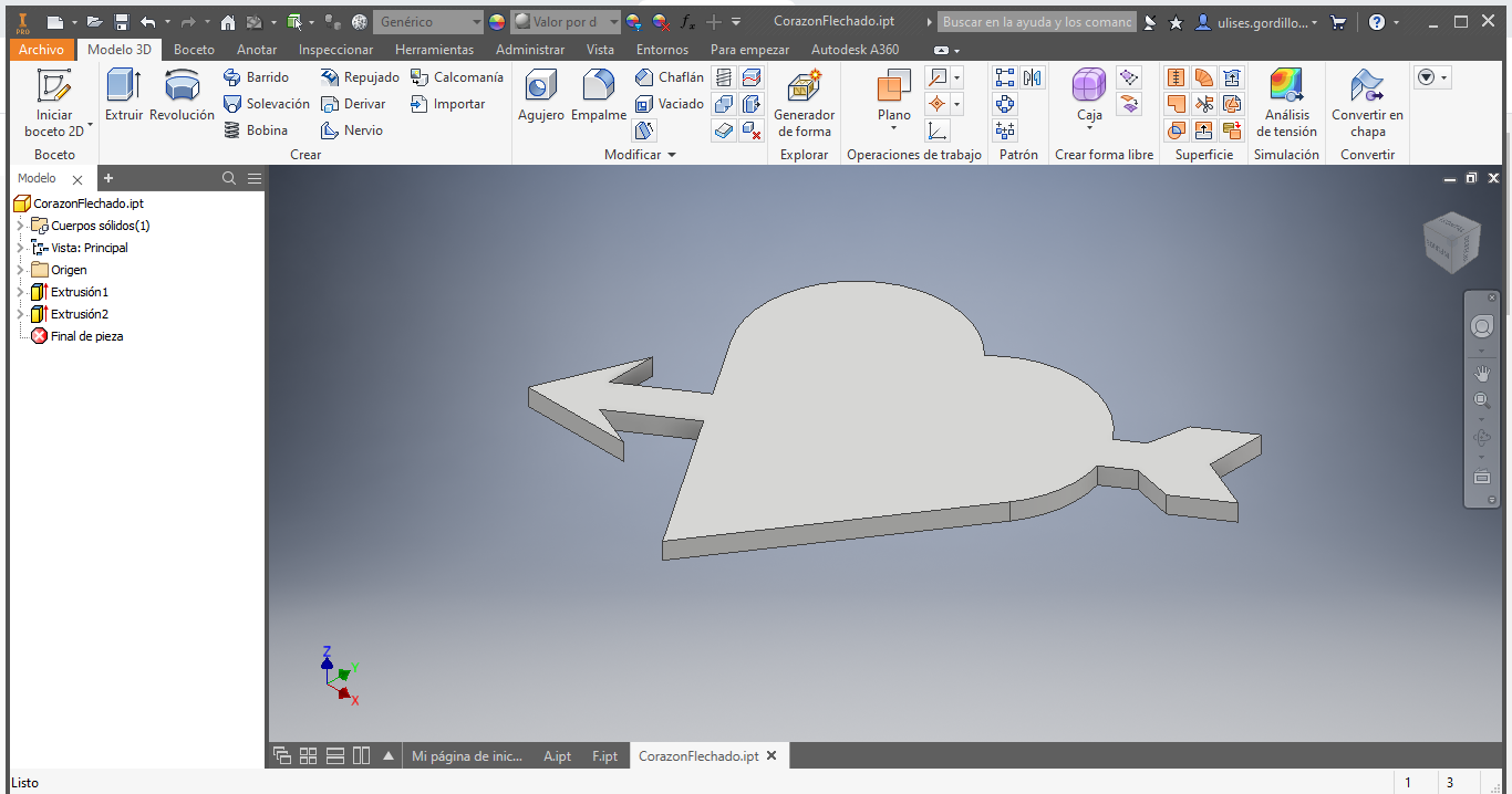
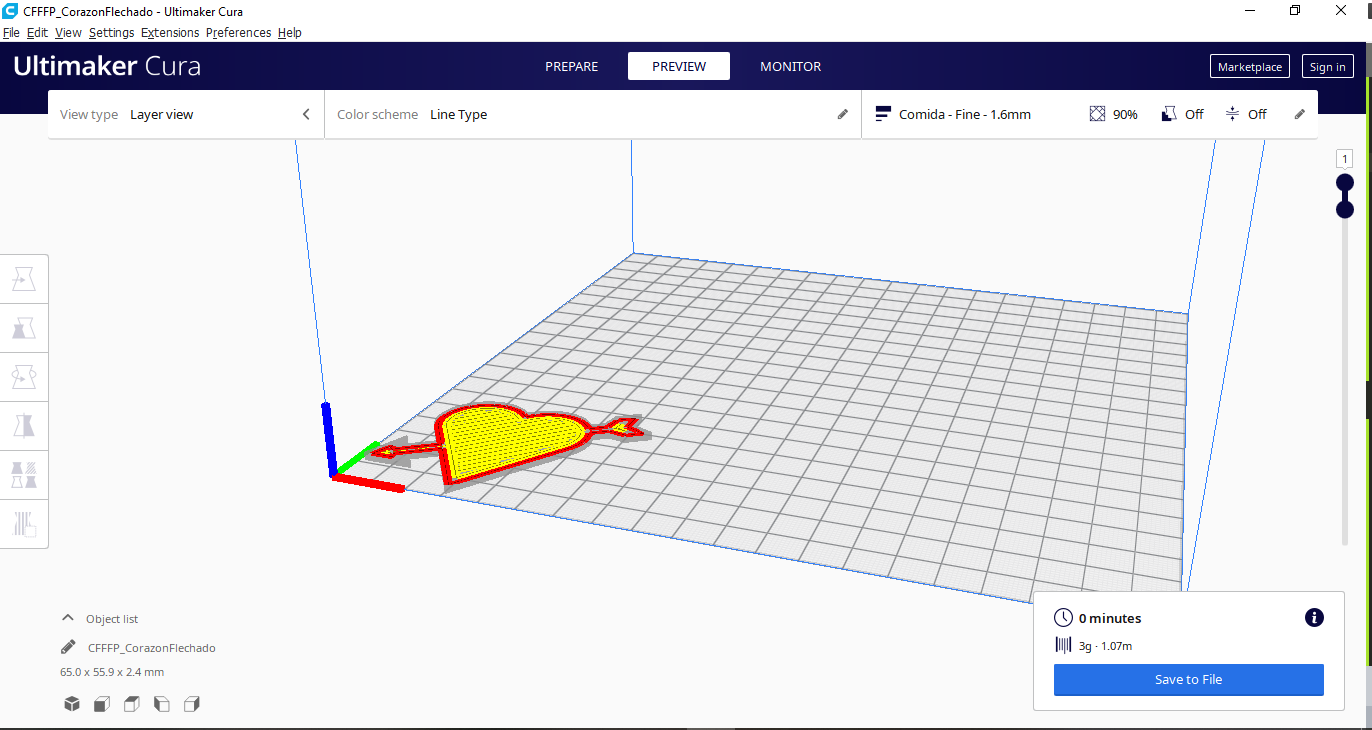
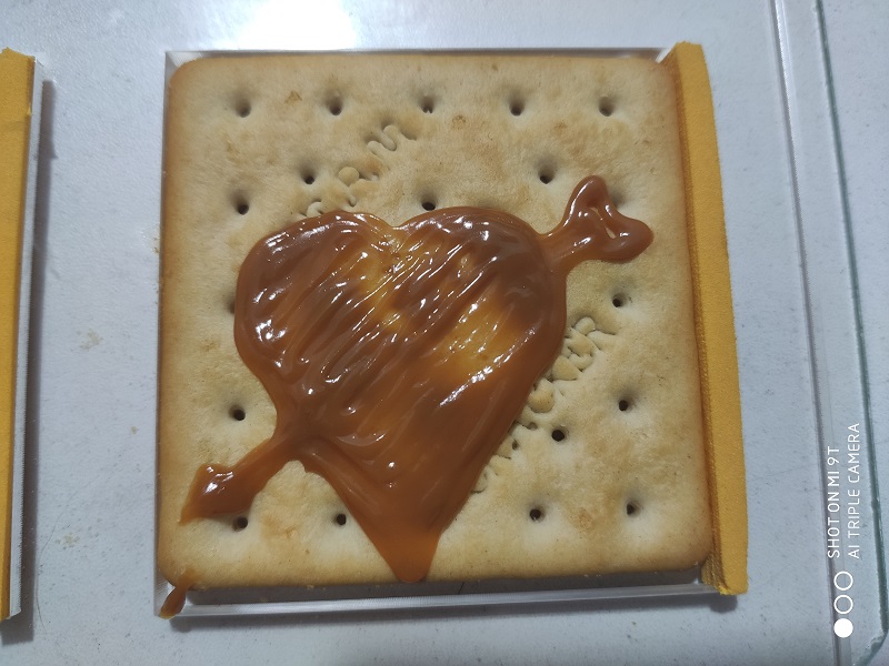
Let’s try with an arrowed heart:
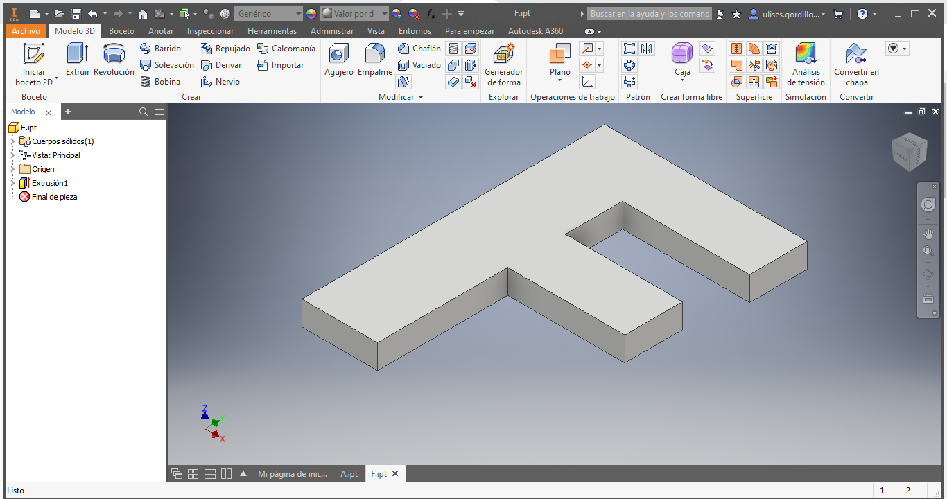
Then with the letter F:
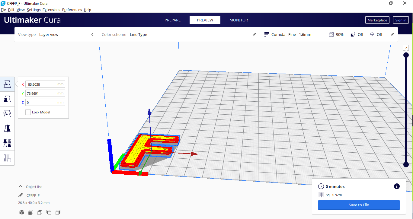
Here the letter F sliced:
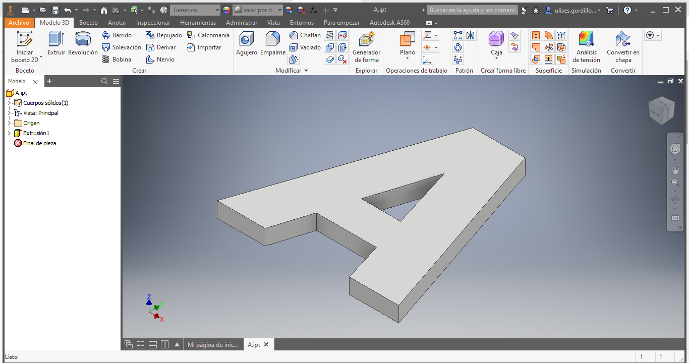
Then with the letter A:
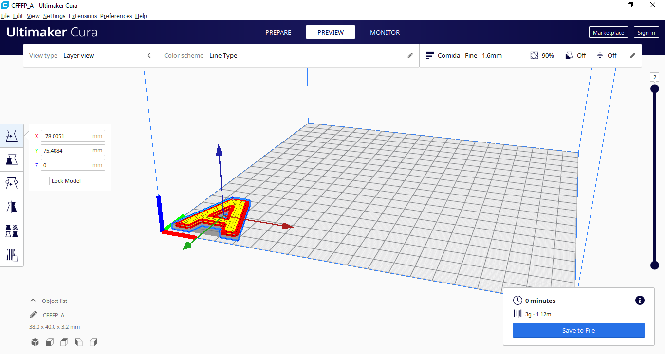
Here the letter A sliced:
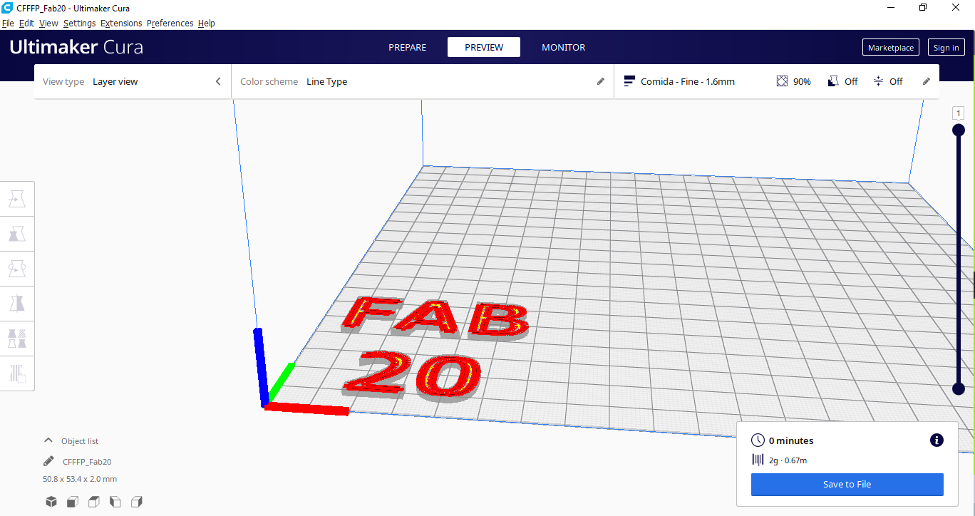
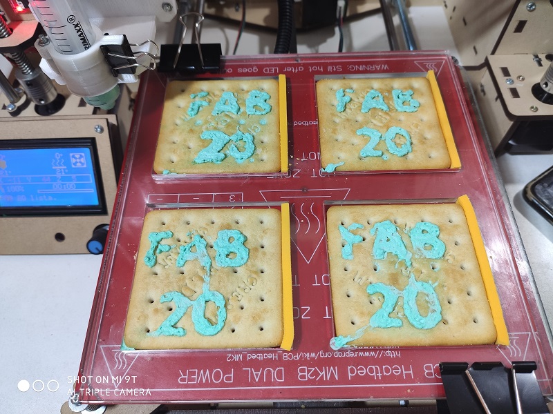
Then with the name of the 3D printer for decoration, FAB 20:
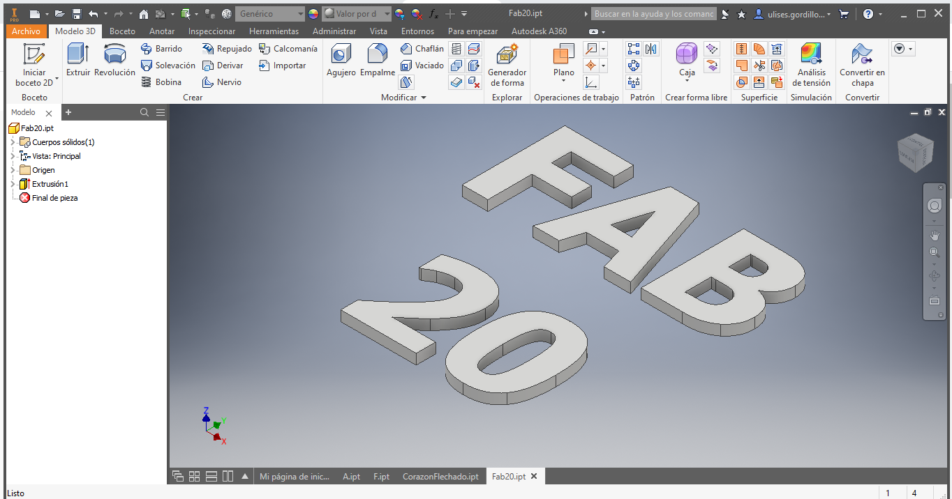
Here the Text FAB 20 sliced:
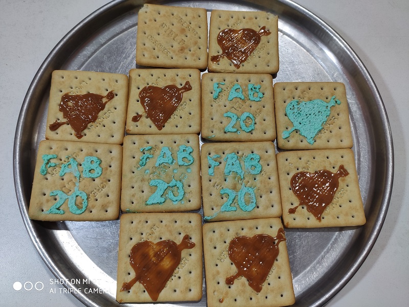
Sample with chocolate delicacy
We will test on a rectangular cookie
Here we have the chocolate delicacy, placed in a 20ml / cc syringe.
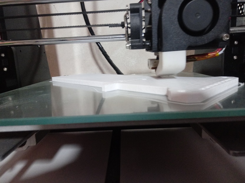
We can see a result of one of the tests:
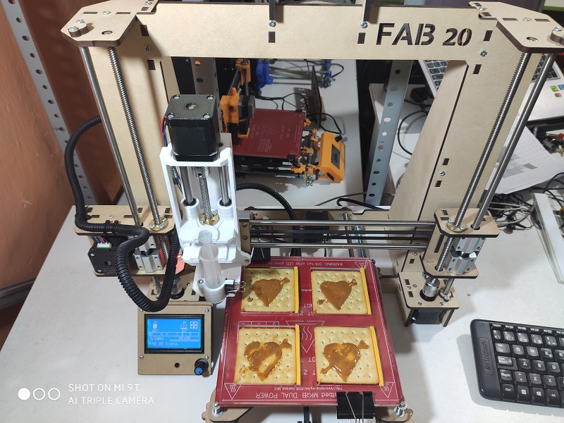
Here we can the printing process:
Here we see several tests performed, all only differ from the starting height as a 0,0,0 point of the coordinates.
Try a square on a cake:
Try the letter F on a cake:
Sample with Cake Cream
Now we will use cream for cakes:

There we have the evidence of the arrowed heart
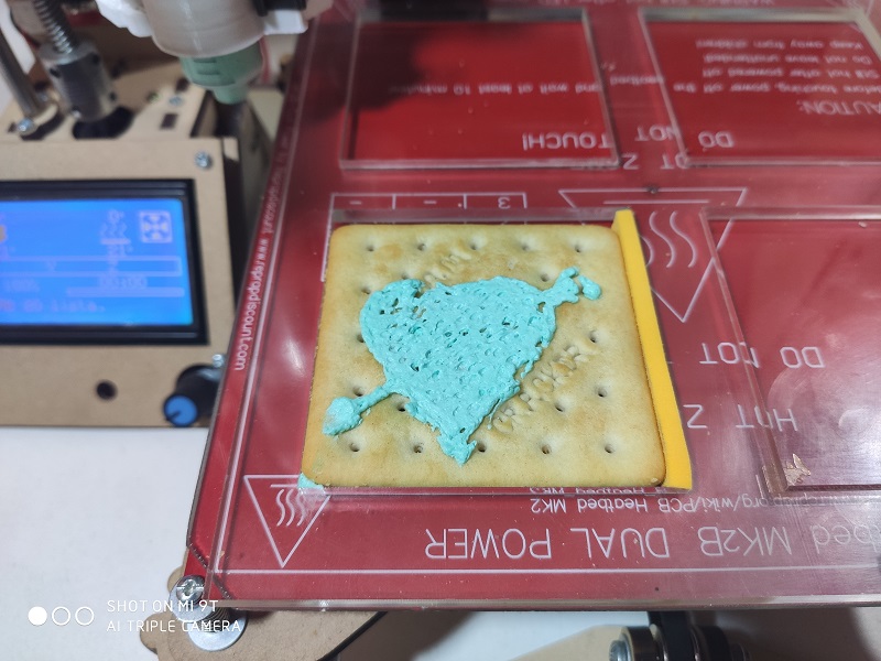
Here we can the printing process:
Here we see several tests performed, all only differ from the starting height as a 0,0,0 point of the coordinates.
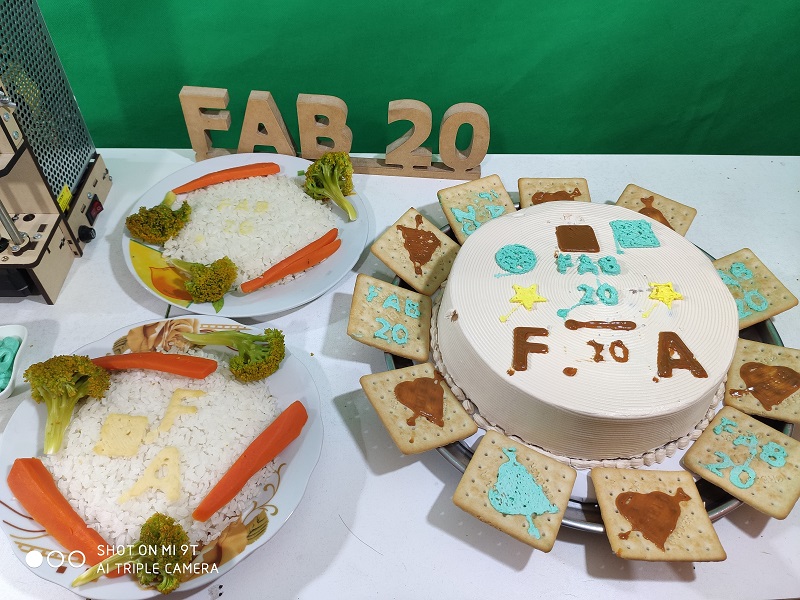
Now we will print on the cake
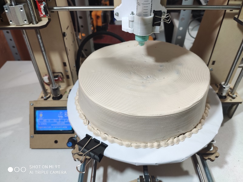
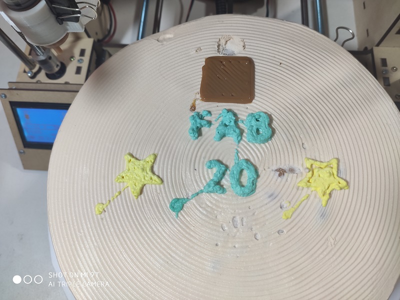
There we have the text of FAB 20, 2 stars and a rectangle
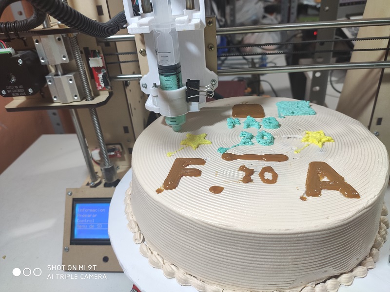
There we have the letters of F and A on the cake
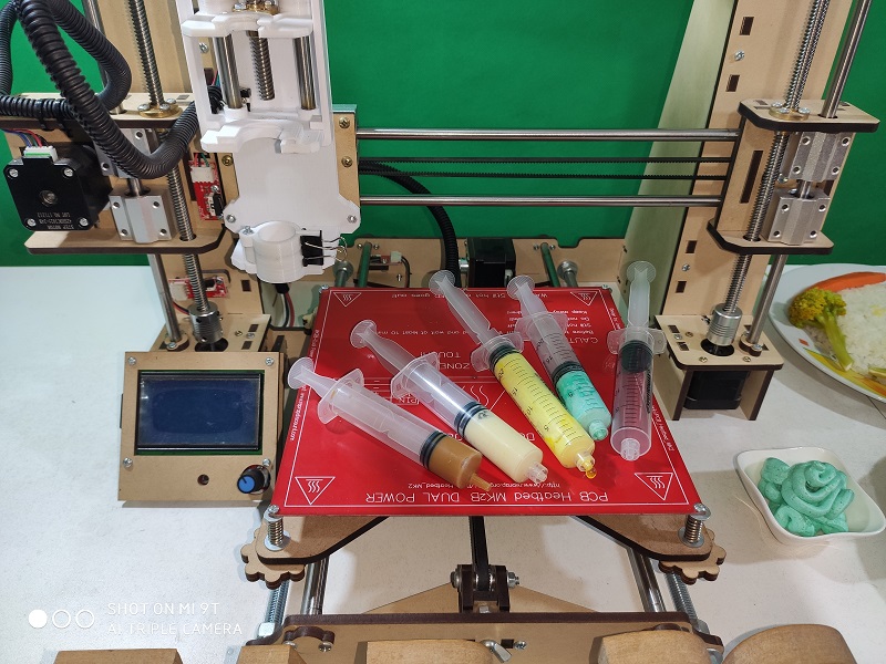
Sample with Mashed Potatoes
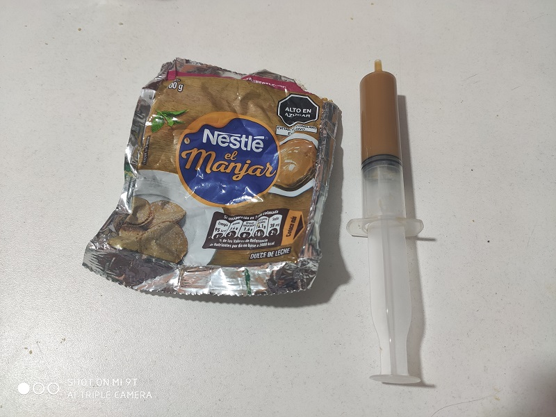
Now we will prepare mashed potatoes with a commercial solution, as we see in the image:

Here we have the mashed Potatoes, placed in a 20ml / cc syringe.

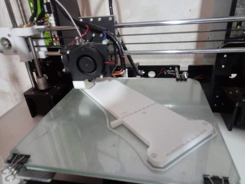
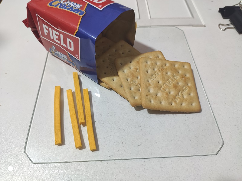
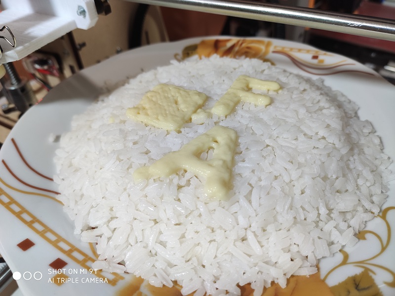
We tested the text FAB 20, printed on rice on a flattened surface.

We tested the letter A and F, printed on rice on a flattened surface.
Here we can see the printing process:
Results
Chocolate Delicacy: For the printing with chocolate delicacy, a commercial one was used, it turns out that it has the ideal viscosity for 3D printing
Cream for Cakes: For the impression with whipped cream for cakes, it was made with cream bought in a local pastry shop, we had to adapt to their behavior.
Mashed Potatoes: For printing with mashed potatoes, it was prepared to have a really good viscosity, but we can control this viscosity since we can add more liquid to make it more viscous.
On the surfaces to be printed:
- The cookies had an uneven surface, caused by baking, which caused it to not print finely.
- The cake was bought from a pastry shop, and it also had a non-level surface, so we only printed one but we had to do it by areas.
- On the rice, we make a flattening with a container so that we achieve the largest flat surface.
| Components | Features |
|---|---|
| Chocolate Delicacy | Viscosity Ideal for printing |
| Cream for Cakes | Very viscosity, printing is difficult |
| Mashed Potatoes | We can control the viscosity with the preparation |
SOME IMAGES:

The Designed Files
BOM
The list of components are:
| Item | Description | Quantity |
|---|---|---|
| 1 | Attiny44 | 1 und |
| 2 | Connector 6p | 1 und |
| 3 | Button | 4 unds |
| 4 | Resistance | 5 unds |
| 5 | Potenciometer | 1 und |
| 6 | Buzzer | 1 und |
| 7 | Capacitor 18pF | 2 und |
| 8 | Crystal 12MHz | 1 und |
| 9 | Arduino Mega | 1 und |
| 10 | Ramps 1.4 | 1 und |
| 11 | Driver A4988 | 4 unds |
| 12 | LCD Graphics | 1 und |
| 13 | Smooth Rod 50m x 8mm | 6 unds |
| 14 | Threaded Rod 35mm x 8mm | 2 unds |
| 15 | Bearing 8mm | 11 unds |
| 16 | Bearing 8mm | 11 unds |
| 17 | Steppers | 5 unds |
| 18 | Nuts 8mm | 20 unds |
| 19 | Bolts 1/8” x 1” | 50 unds |
| 20 | Springs 20mm x 5mm | 4 unds |
| 21 | Syringes 20ml | 4 unds |
| 22 | 3D Printed Parts Set | 1 und |
| 23 | Laser Cut Parts Set | 1 und |
The files to Replicate:
The files are the following:
| Description | Files |
|---|---|
| Marlin Firmware | Marlin Firmware |
| FAB 20 Printer 3D | FAB_20_Design-3D.zip |
| Extruder Food | Extruder_FA_20_Food.zip |
| Test Files | Files_Test_FAB_20.zip |
| Hand Control | Hand_Control_FAB_20.zip |