4. Computer controlled cutting
Group Assignment:
- Characterize your lasercutter’s focus, power, speed, rate, kerf, joint clearance and types
Individual Assignment:
- Cut something on the vinylcutter
- Design, lasercut, and document a parametric construction kit, accounting for the lasercutter kerf, which can be assembled in multiple ways, and for extra credit include elements that aren’t flat
GROUP ASSIGNMENT
In this item I work calibrating the laser cutting machine
Laser Cutting Machine
This week I worked with Laser CO2 Machine.
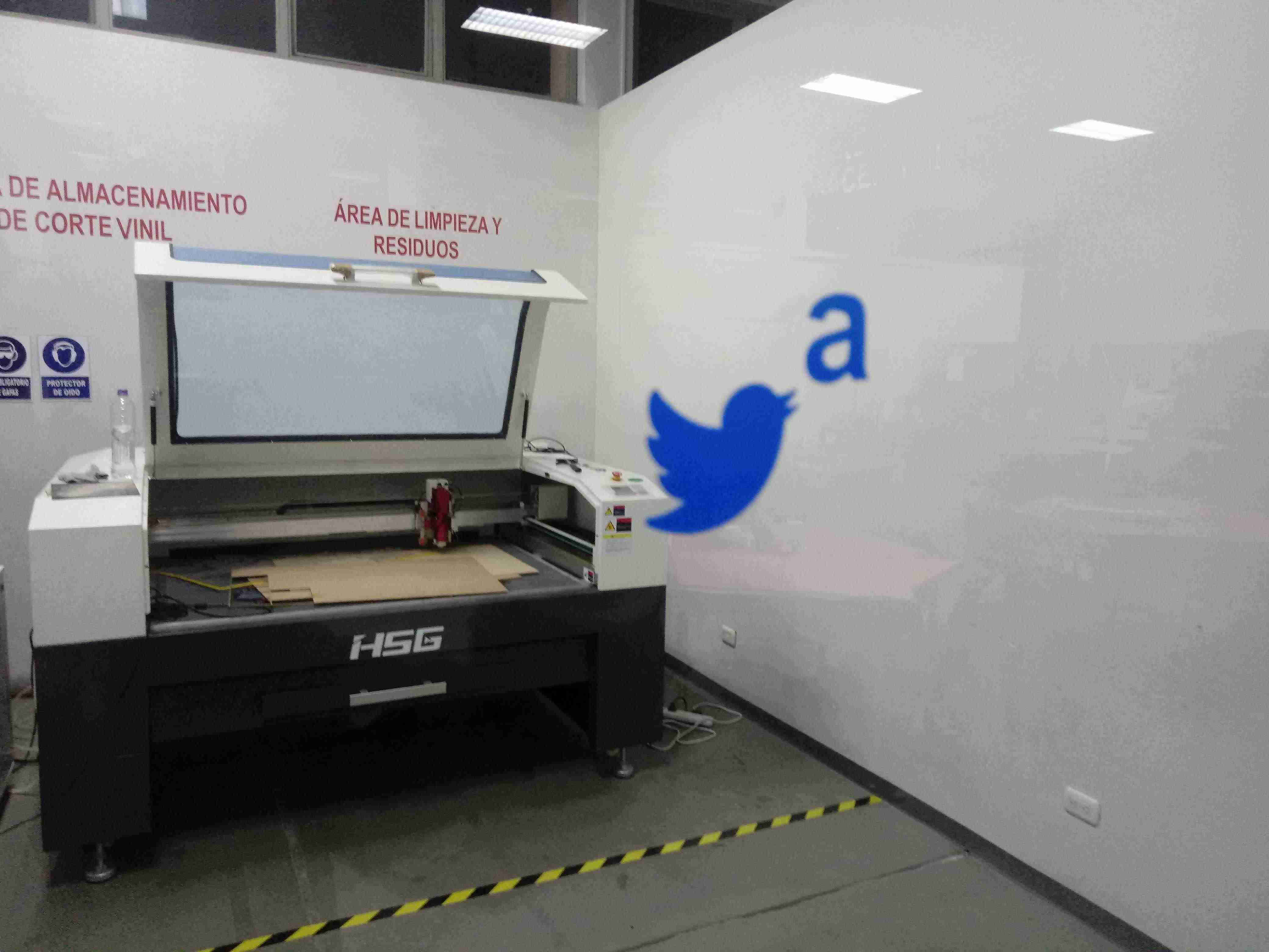
Machine’s features:
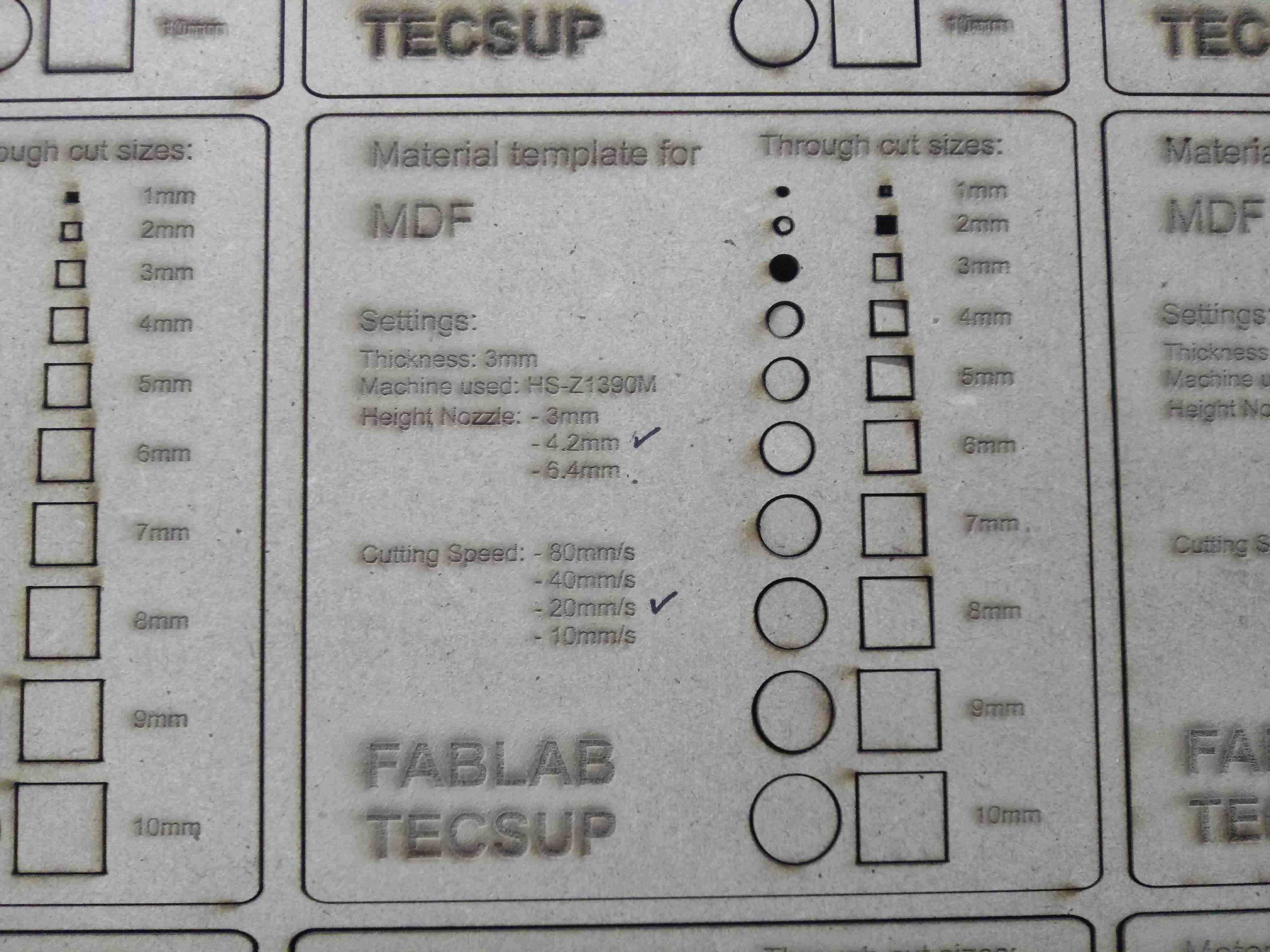
- COMPANY: HSG
- MODEL: HS-Z1390M
- LASER POWER: 100W
Designing
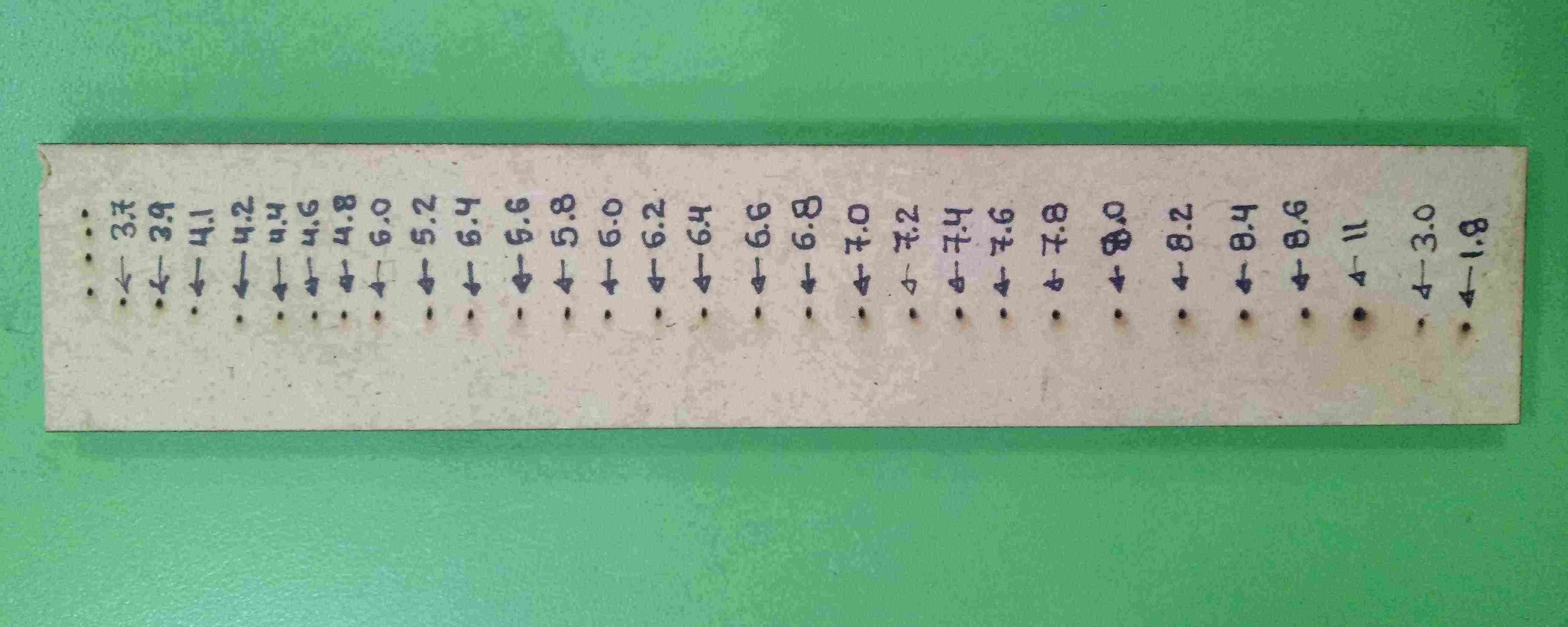
I designed the gauge in AUTODESK INVENTOR, the measurement between each link is 0.2mm
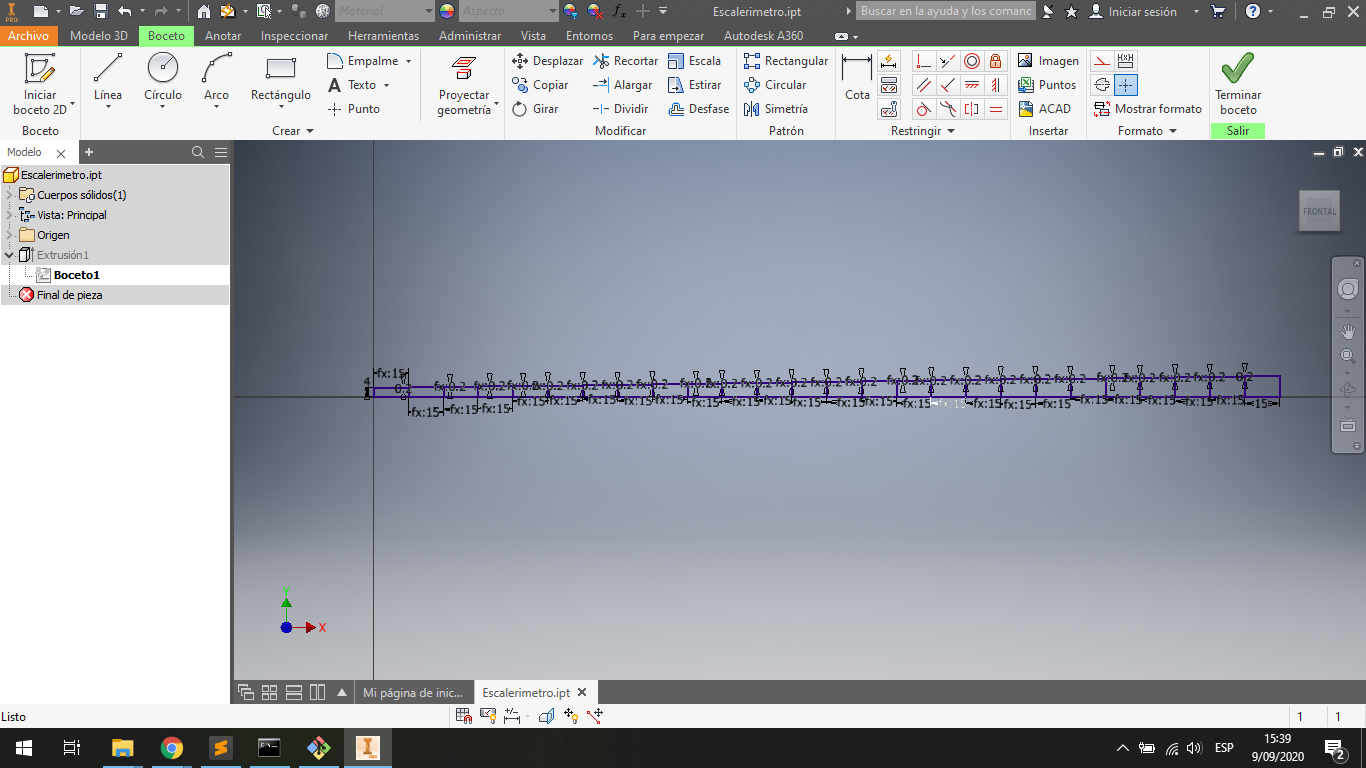
For this file I create a drawing file in the AUTODESH INVENTOR:
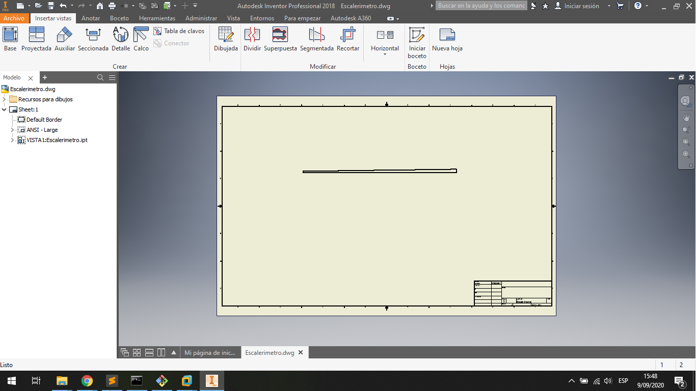
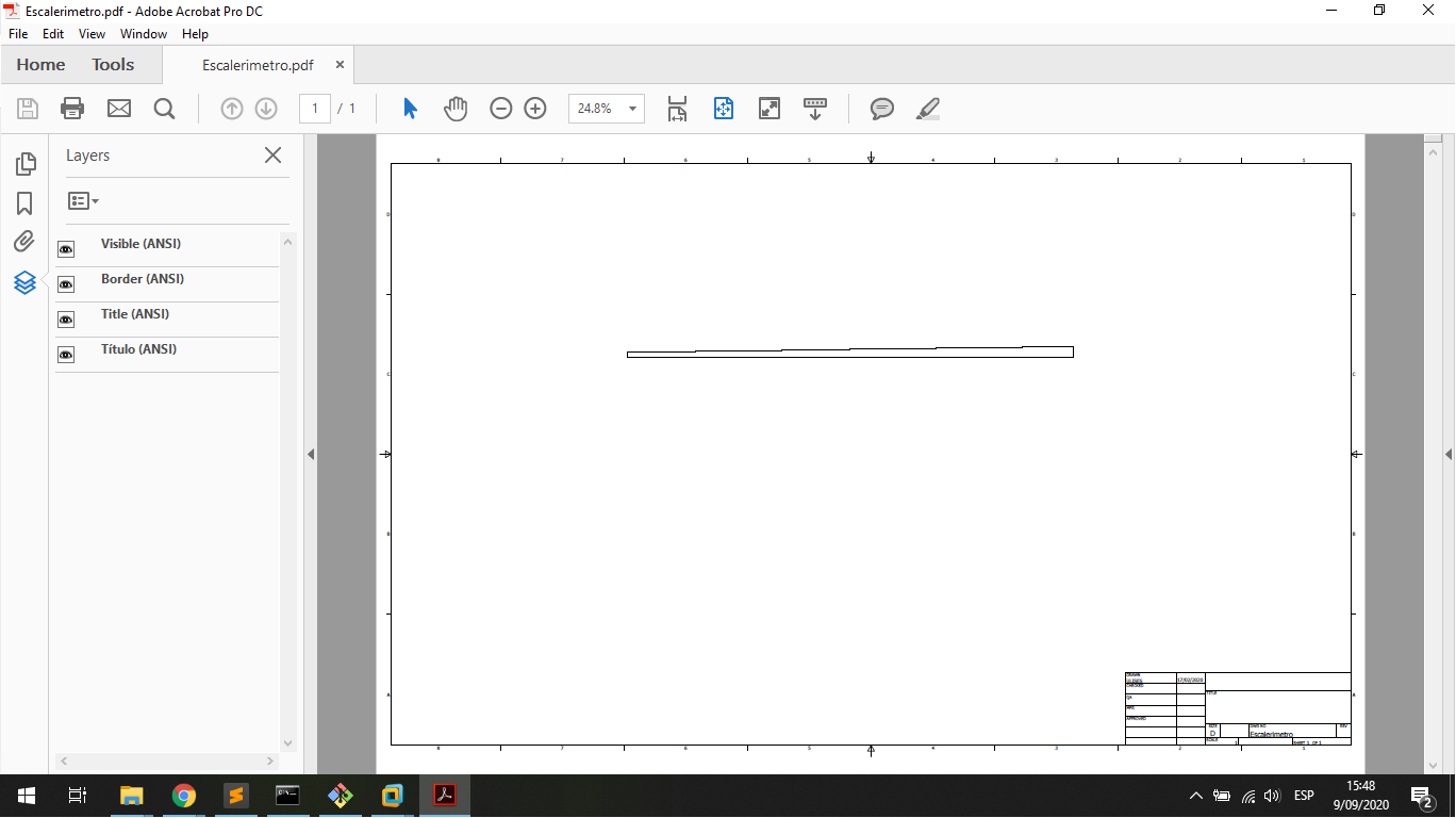
For this file I export the file in a PDF file to work with COREL DRAW:
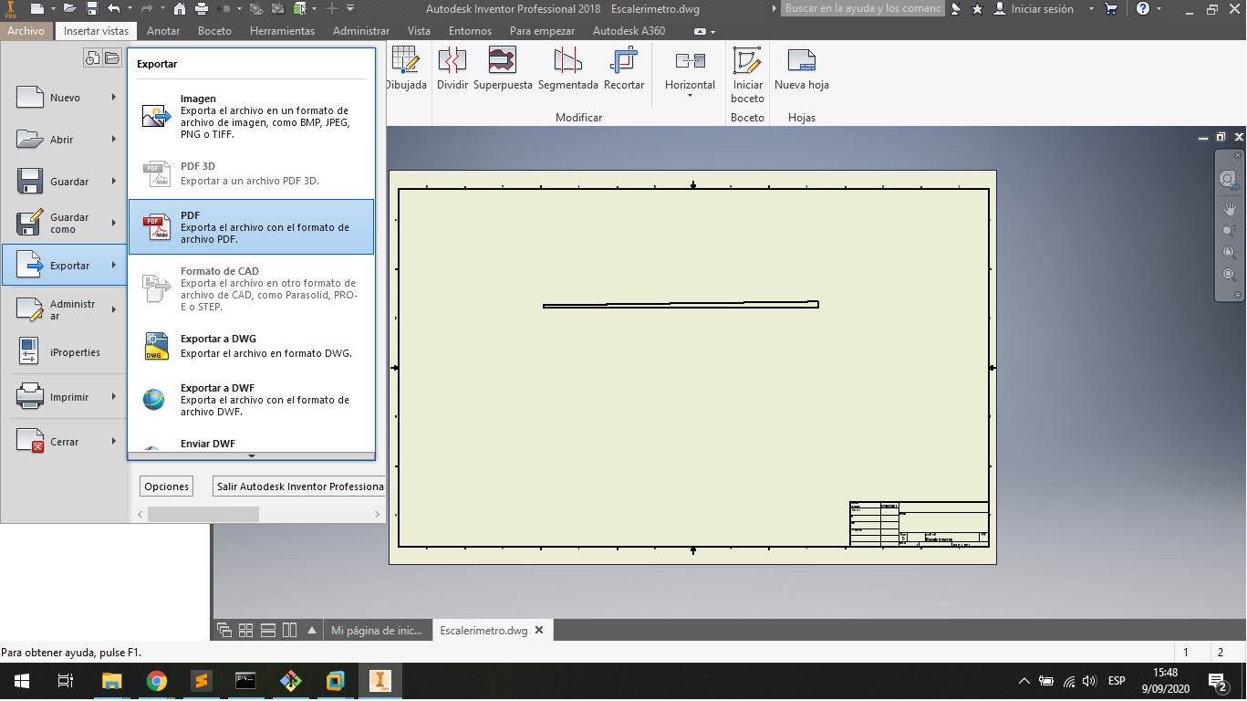
This is the file in PDF, it is necessary to work with COREL DRAW
In COREL DRAW I erase all part that does not require to cutting, and export en DXF file to work with cutting Sfotware.
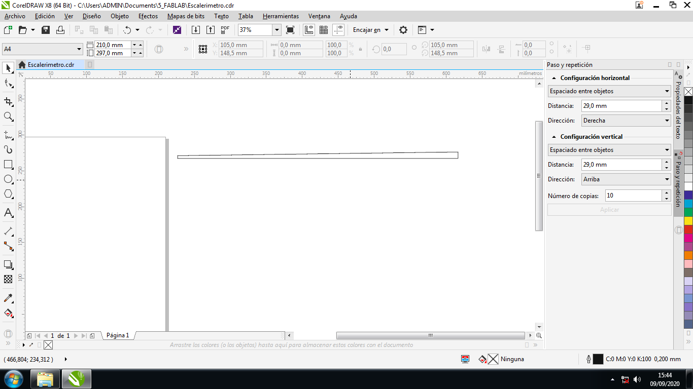
This is the DXF file to Cutting:
Cutting Gauger
For Cutting I use the RDworksV8 software and I run in the command line:
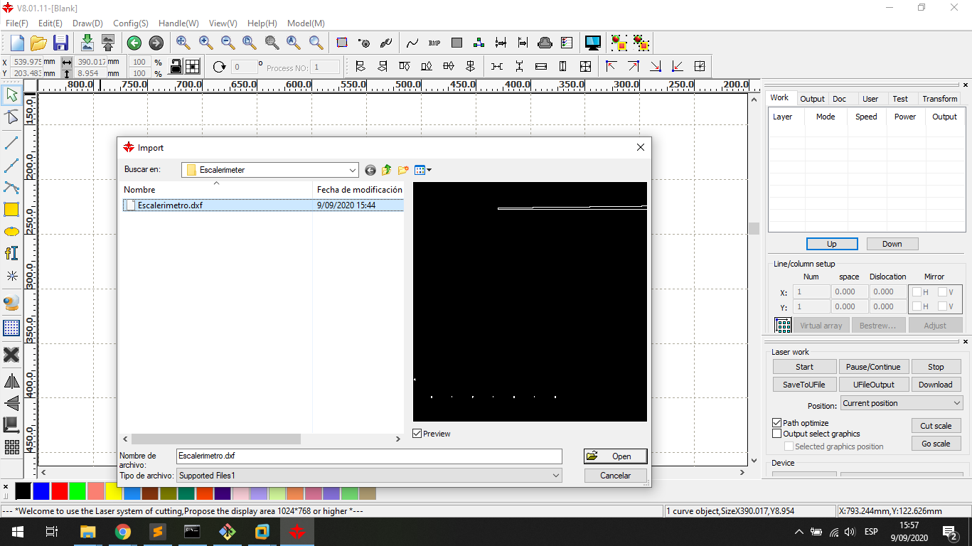
I import the DXF file:
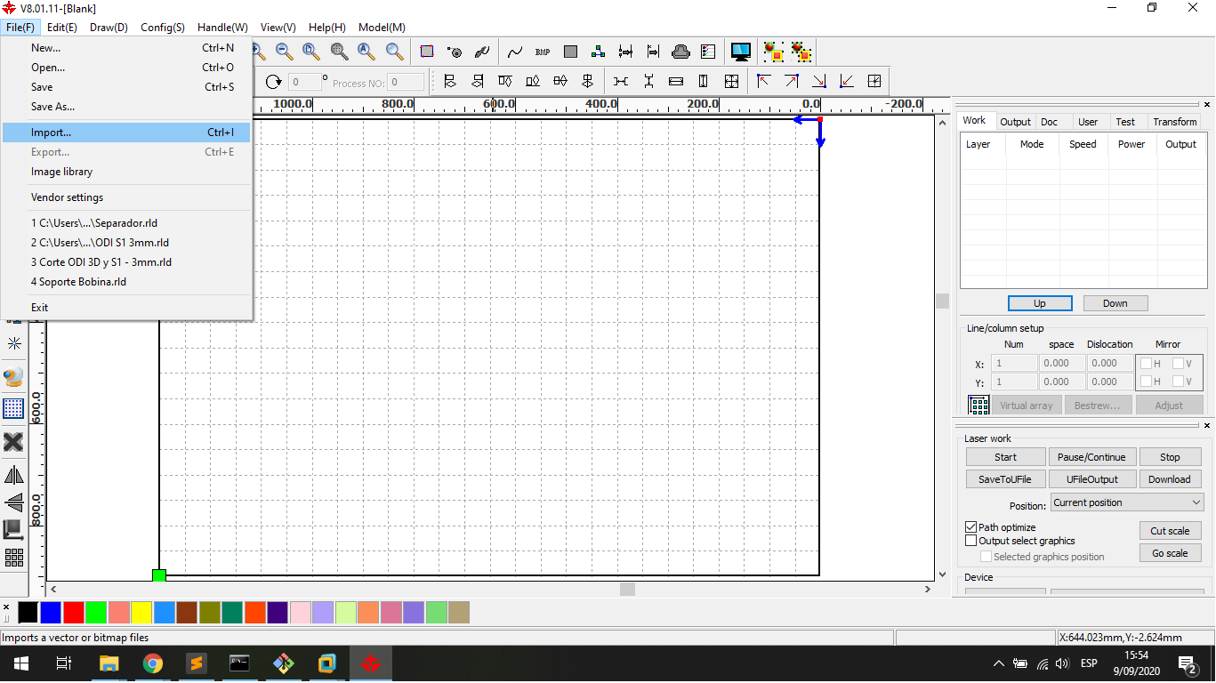
I choose the file in the explorer windows to import:
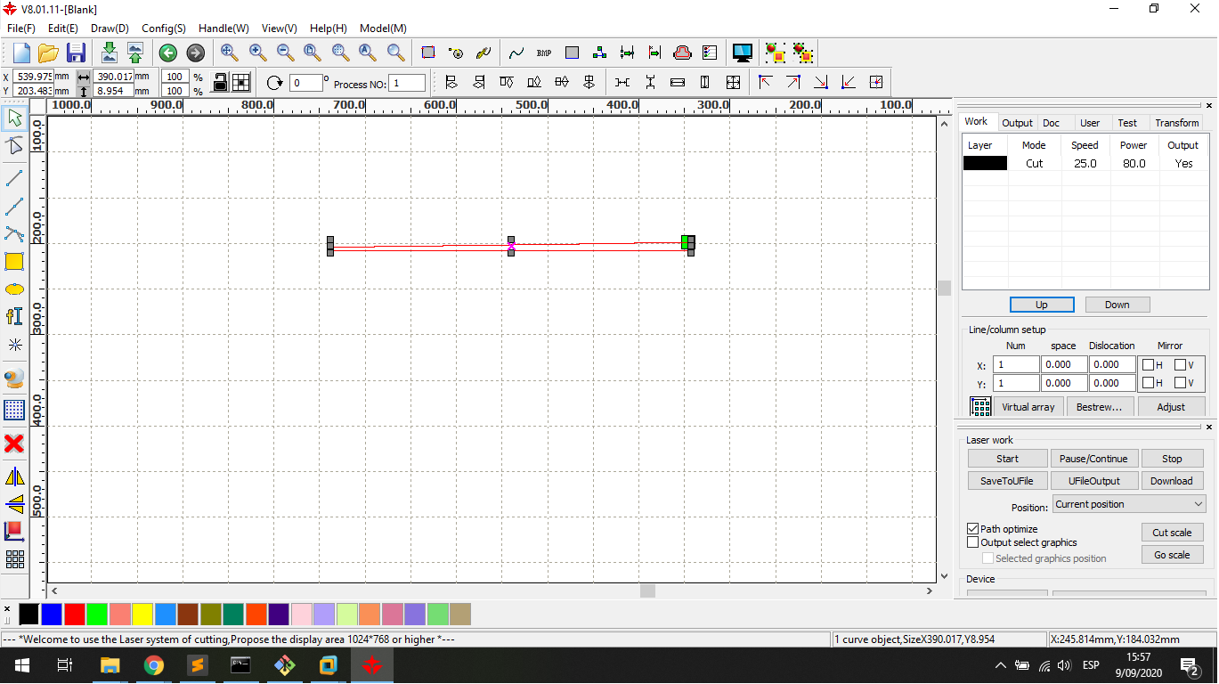
I set the POWER and SPEED to cut 5.5mm thick MDF, in this case:
    Speed = 25mm/s
    Power = 80%
Calibrating
To correct use I measure the best power and speed value to work with acrylic and MDF.
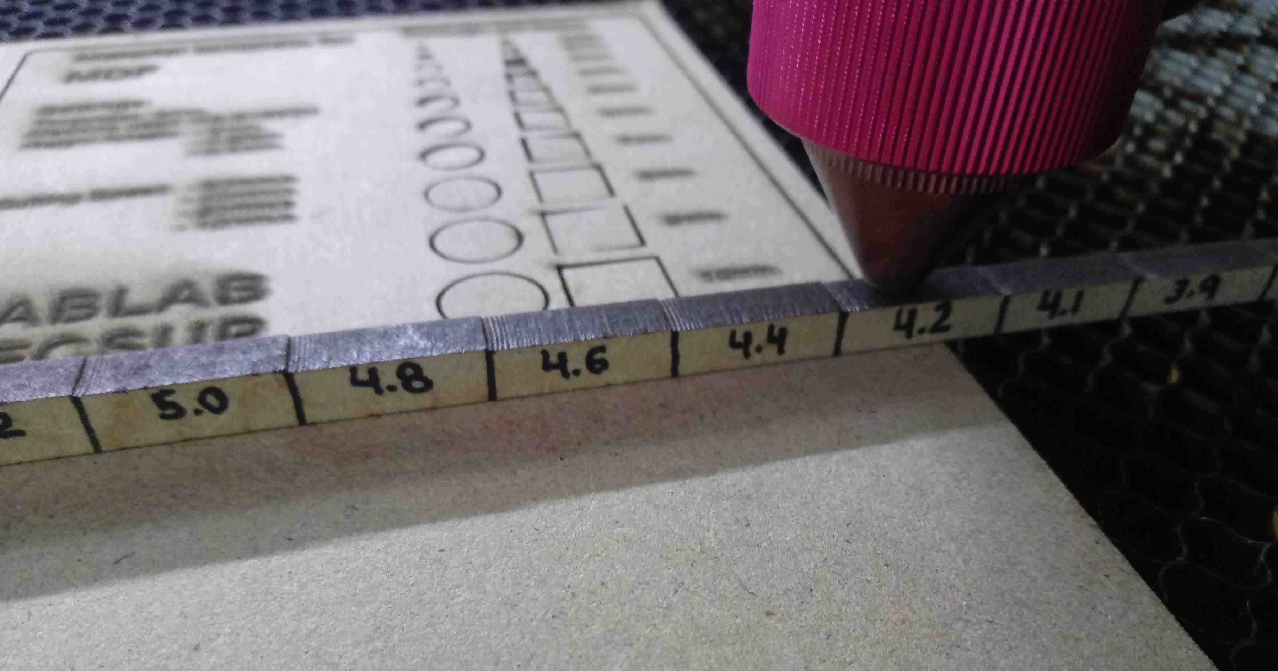
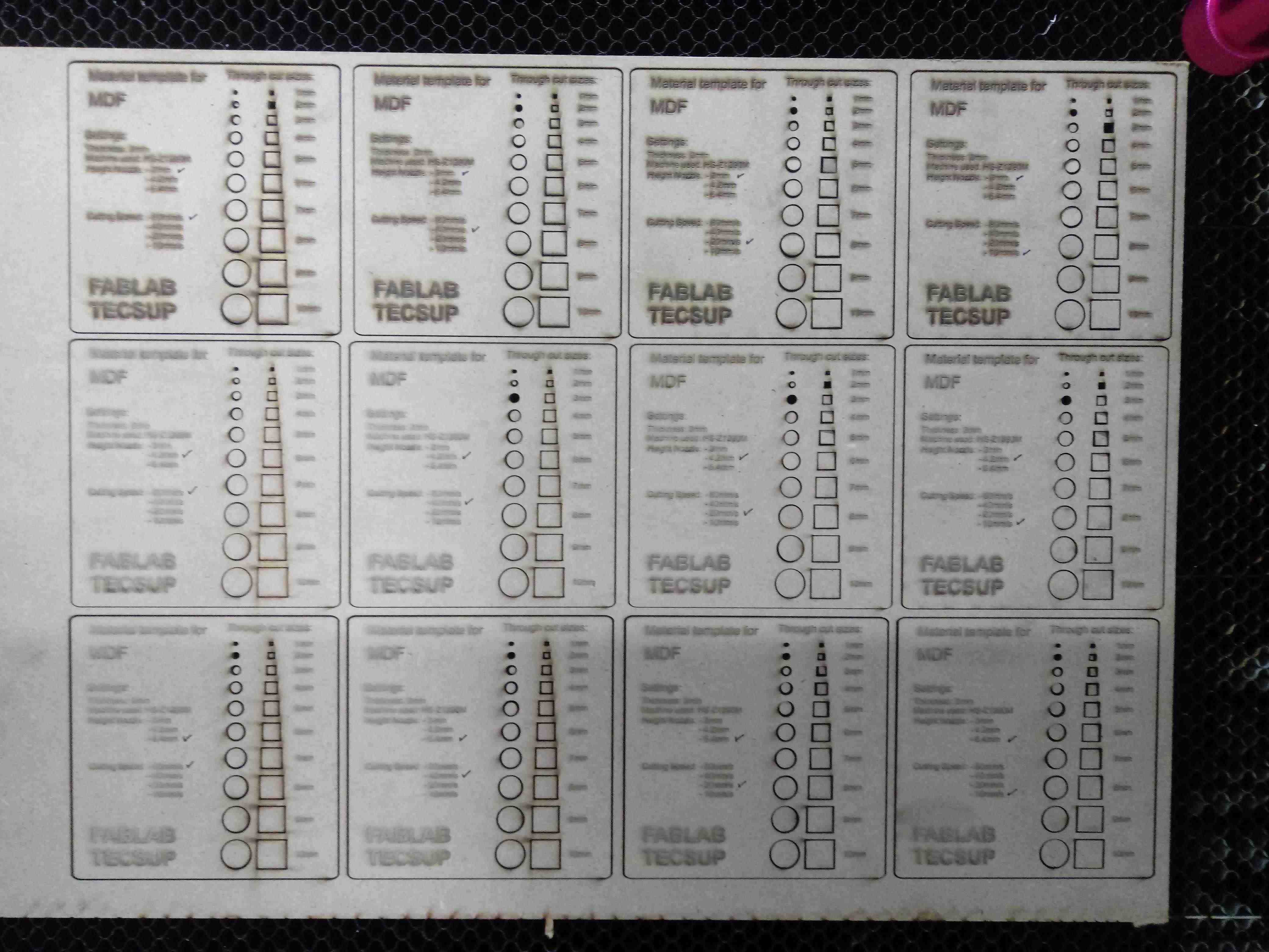
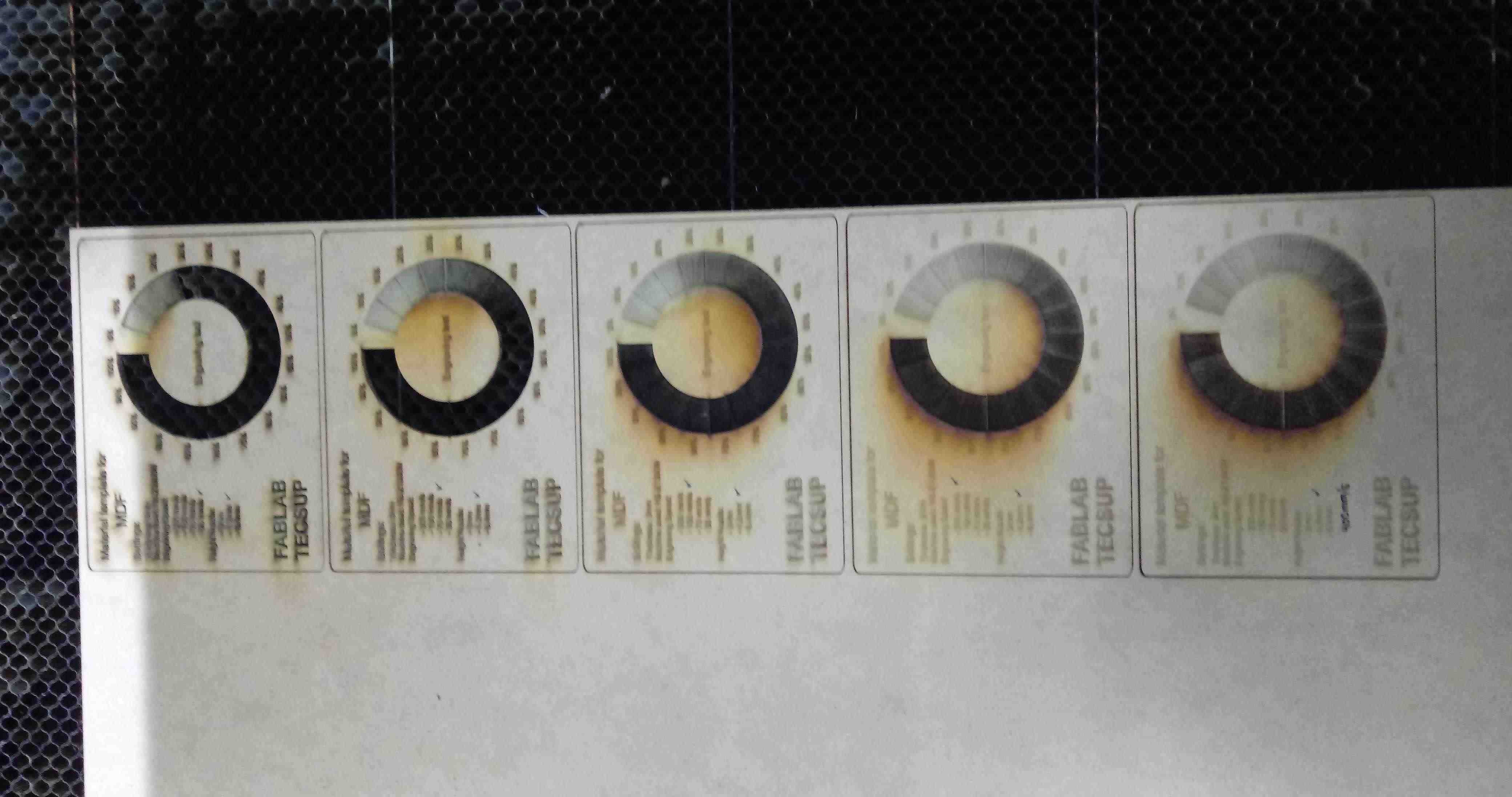
First is necessary calibrate the height of nozzle of machine, then I work whith a laser pulse to have the best height, I sign the measure in each link of the gauger.
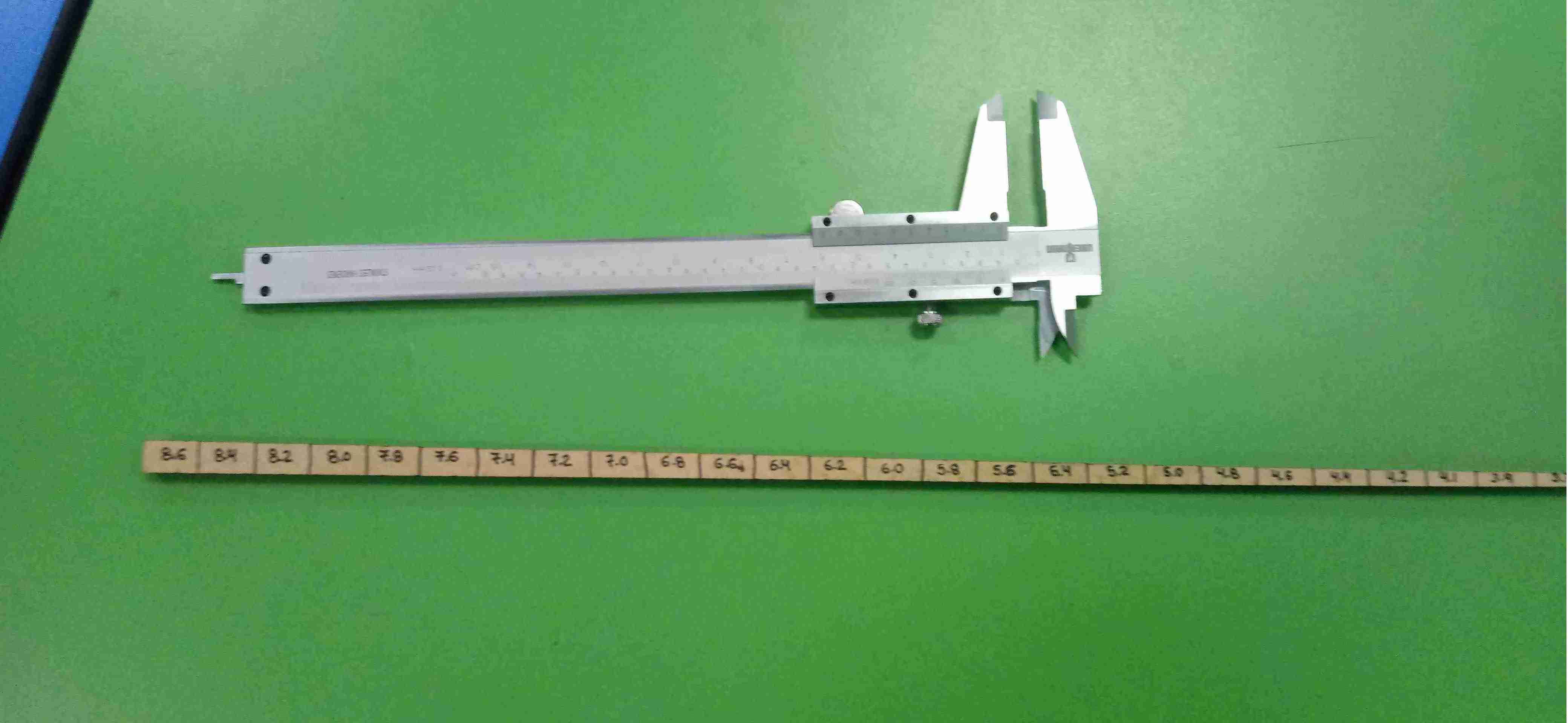
I move the nozzle height about all the measures of gauger:
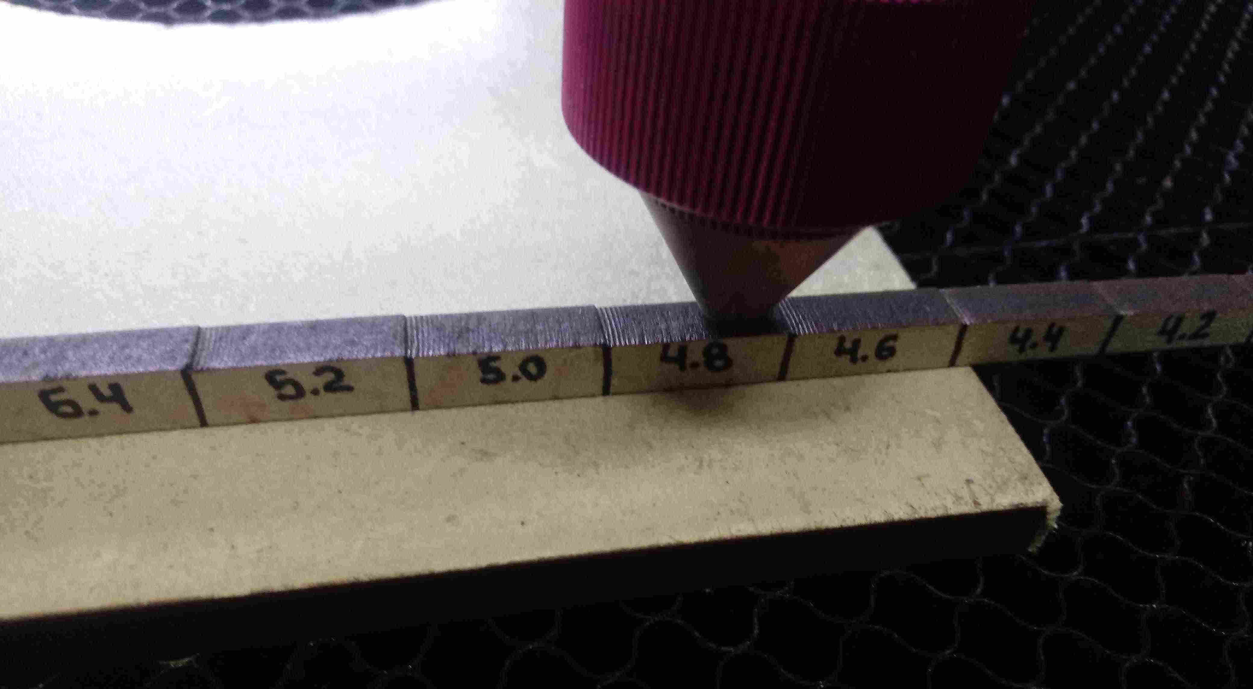
The machine has a PULSE’s button that does a Laser CO2’s pulse
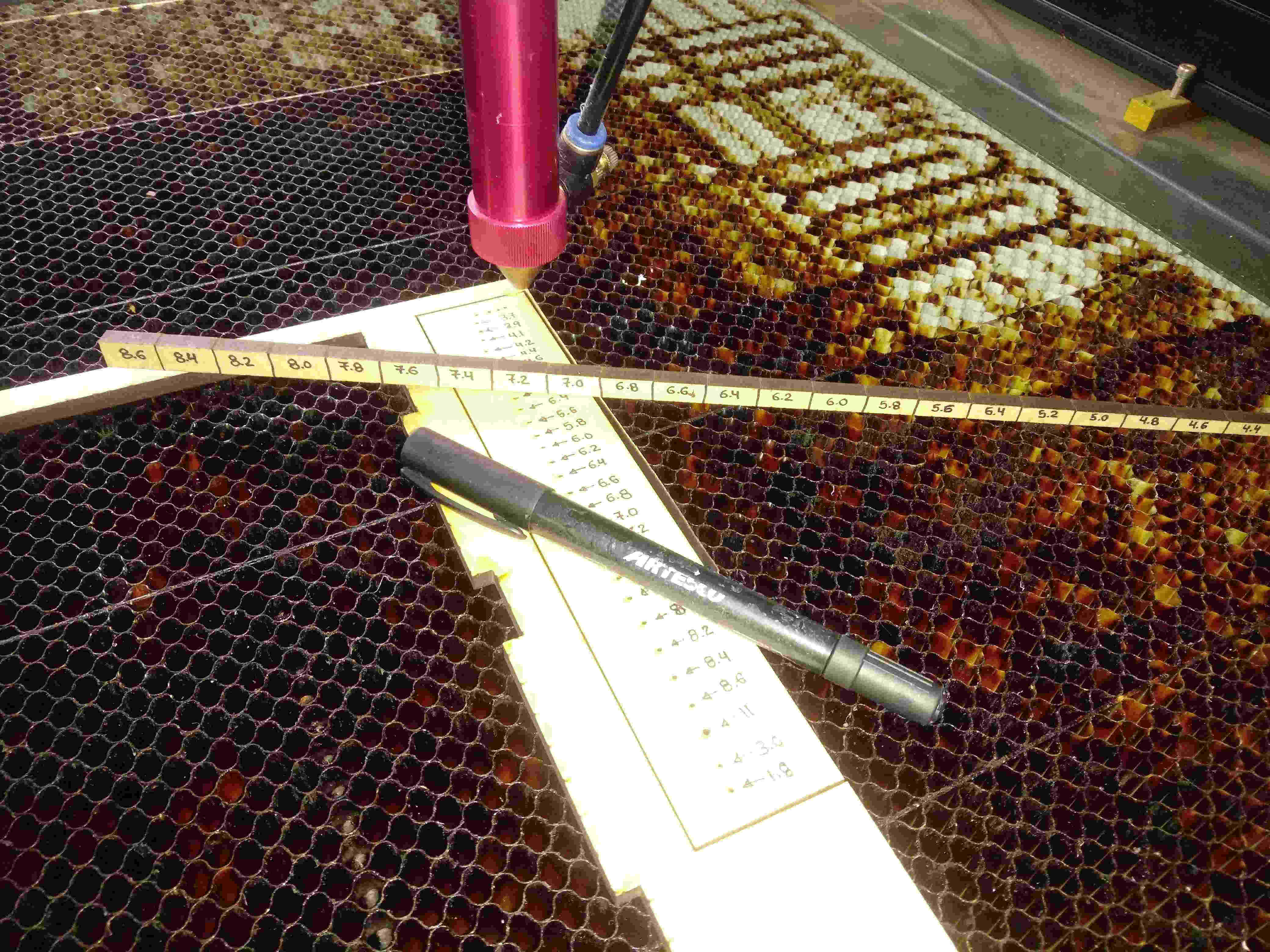
The goal in this step is choose three measures to the Nozzle Height, in my test are:
- 3mm
- 4.2mm
- 6.4mm
They are the smaller cut, for future works I use this heights of the nozzle
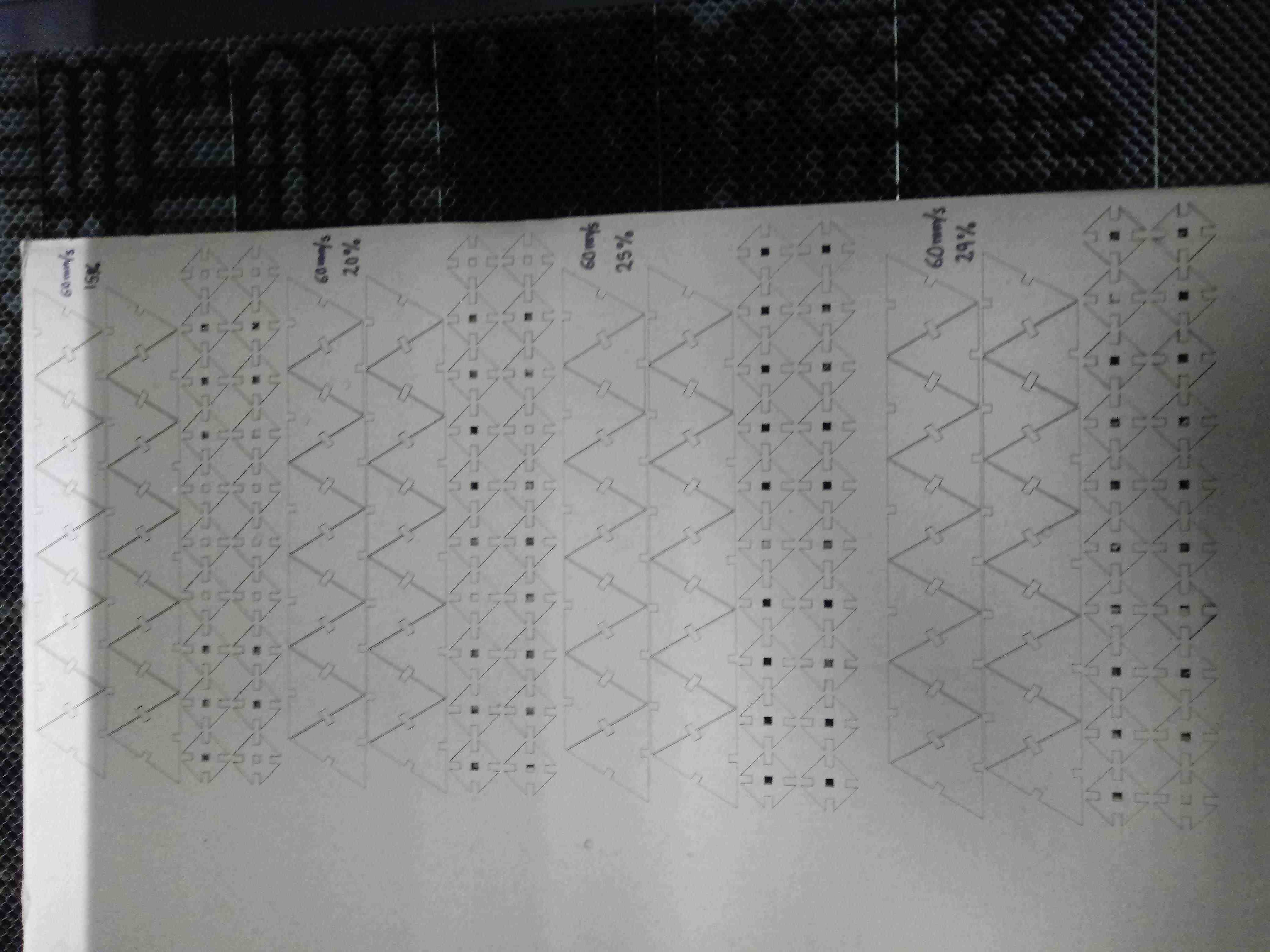
Cutting
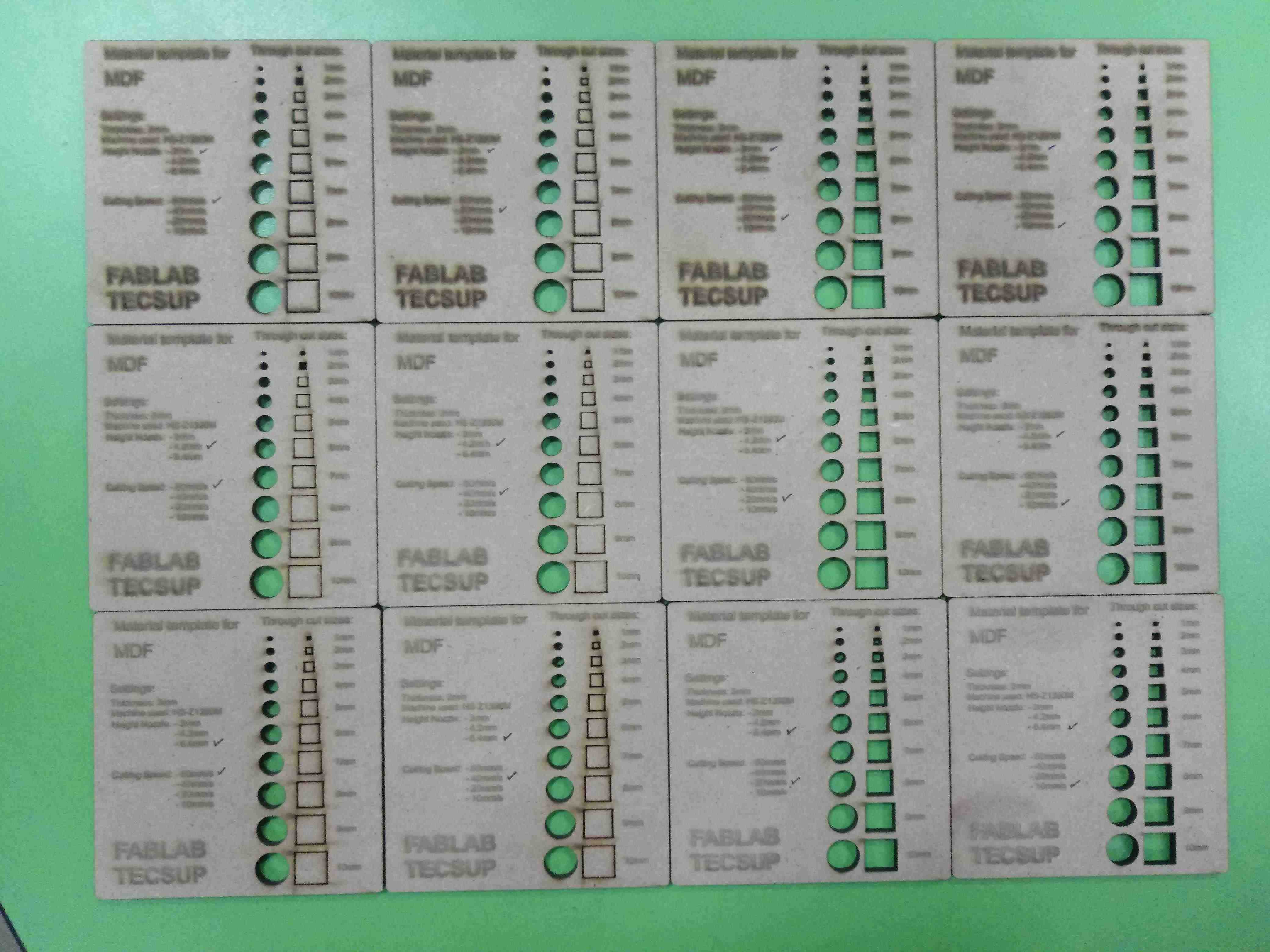
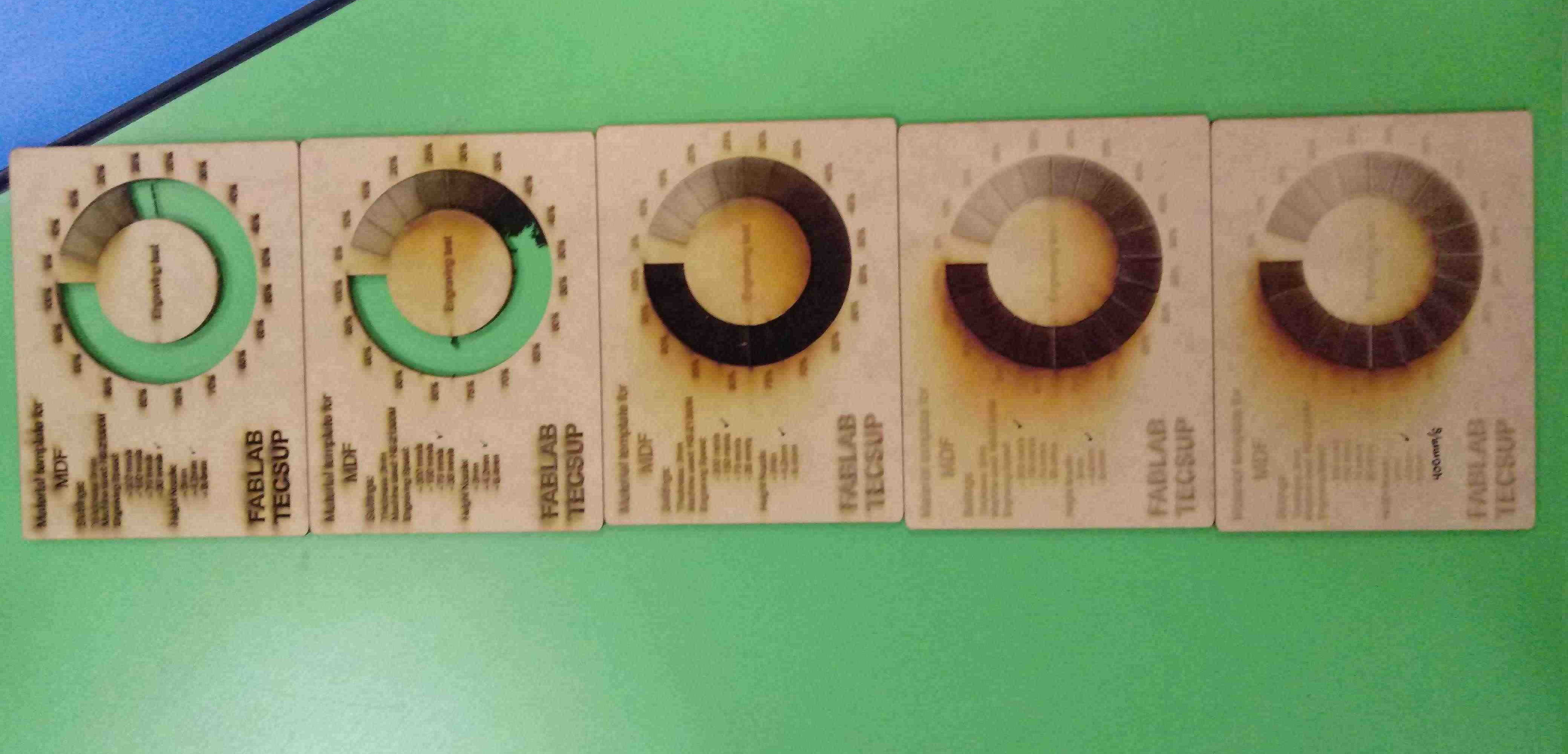
In this work, I cut with the three height of nozzle to find the best cutting.
I work with laser power fixed to 80%
I work with three height of nozzle
| Item | Nozzle Height |
|---|---|
| 1 | 3.0 mm |
| 2 | 4.2 mm |
| 3 | 6.4 mm |
And four velocities:
| Item | Velocity |
|---|---|
| 1 | 10 mm/s |
| 2 | 20 mm/s |
| 3 | 40 mm/s |
| 4 | 80 mm/s |
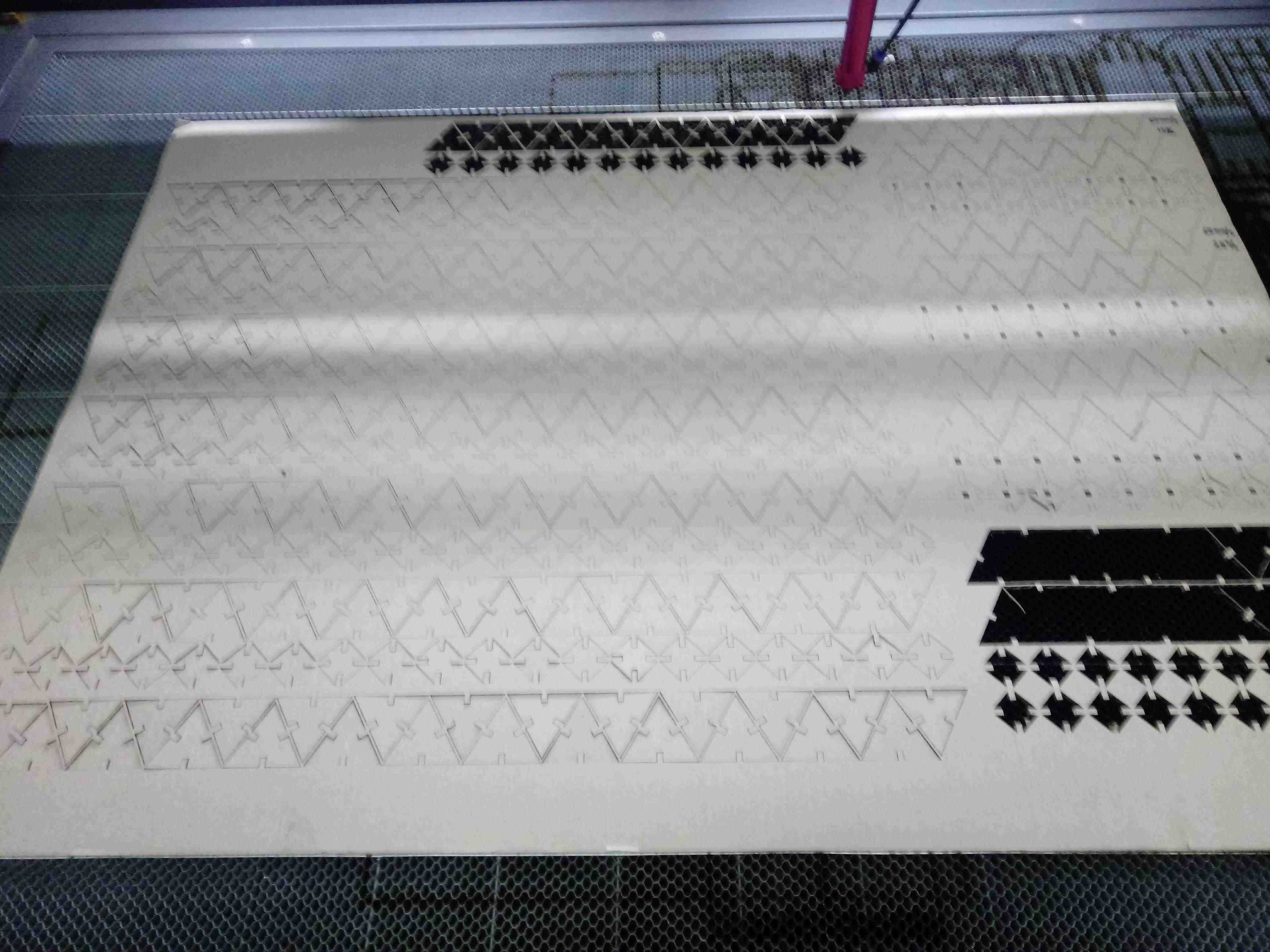
Initializing:
Cutting:
Choosing:
Measuring:
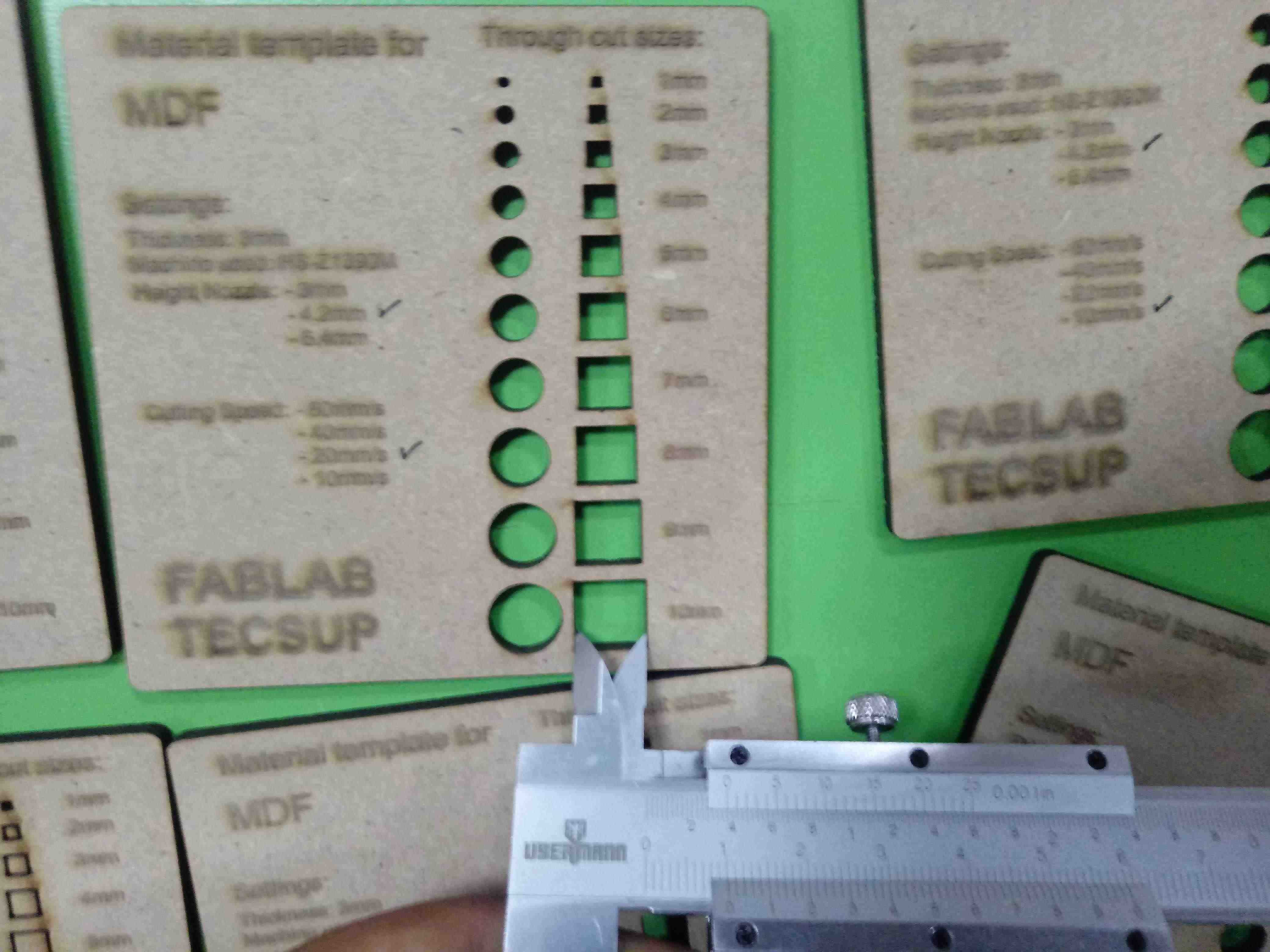
| Height/Velocity | 80 mm/s | 40 mm/s | 20 mm/s | 10 mm/s |
|---|---|---|---|---|
| 3.0 mm | 10.3 mm | 10.2 mm | 10.2 mm | 10.2 mm |
| 4.2 mm | 10.2 mm | 10.1 mm | 10.0 mm | 10.1 mm |
| 6.4 mm | 10.3 mm | 10.2 mm | 10.2 mm | 10.3 mm |
The Best height is to: 4.2 mm height of nozzle
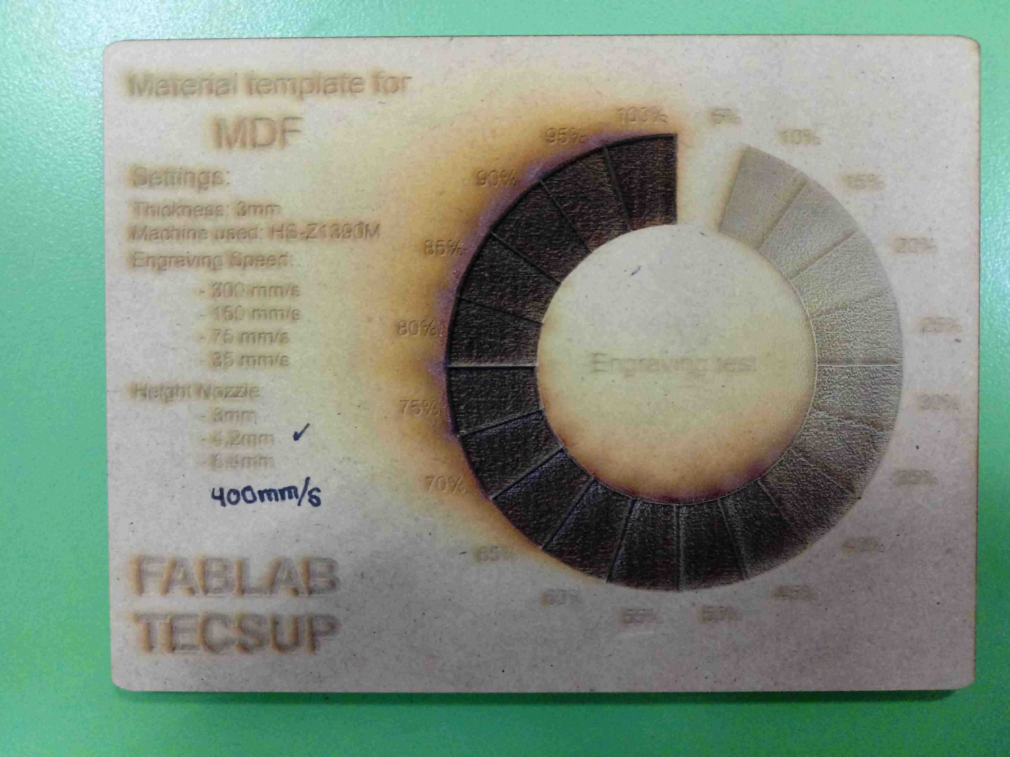
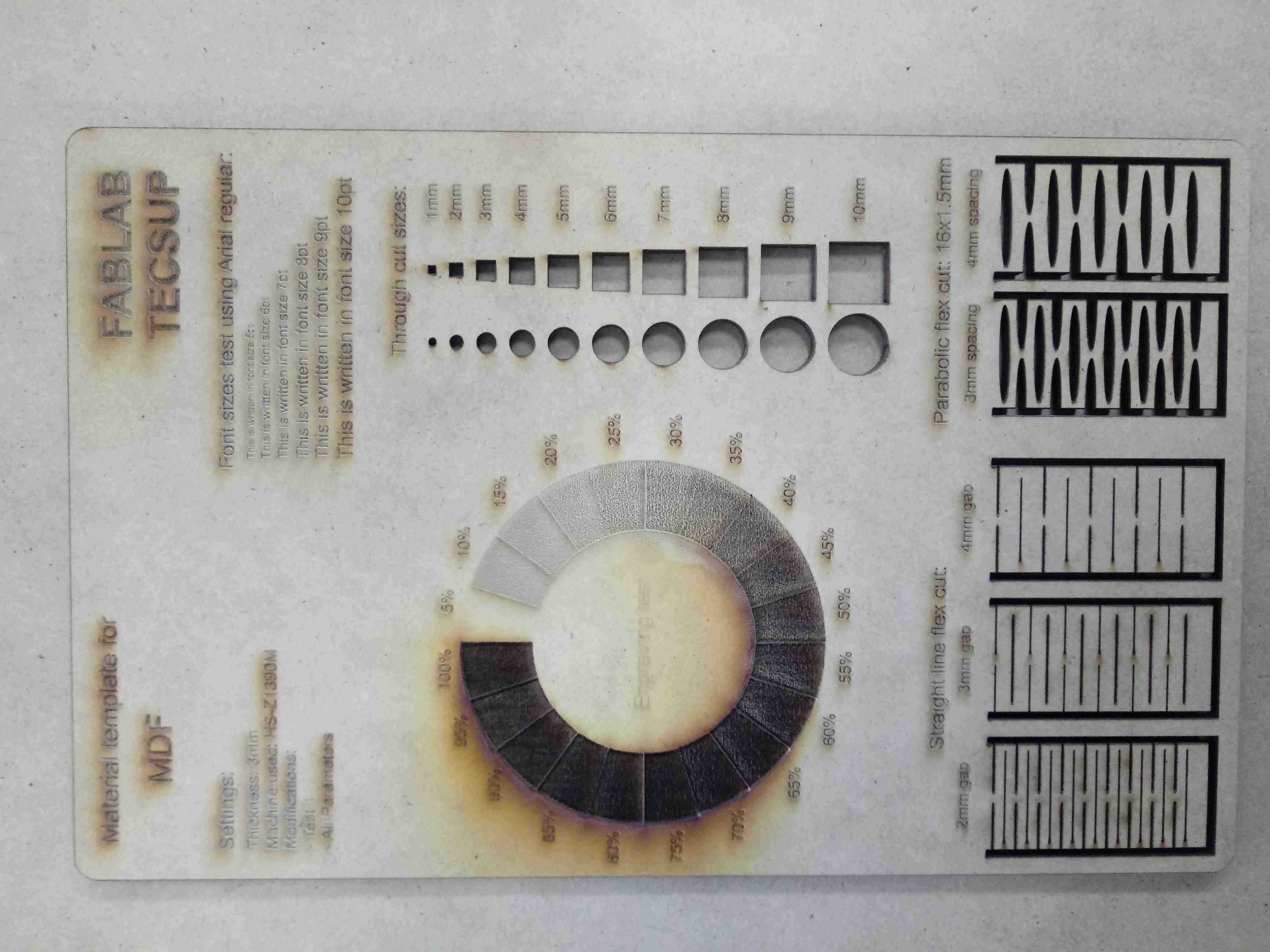
Engraving
In this work, I use the best nozzle height
Individual samples I can see:
I choose to engraving the test with 4.2mm of height of nozzle and 400mm/s of speed:
I choose to cutting the test with 4.2mm of height of nozzle and 20mm/s of speed:
INDIVIDUAL ASSIGNMENT
Design the Parametric Kit
In the following parametric kit I am using Autodesk Inventor software, in this design we will have the design parameters in an excel file, which will allow us to control the design parameters.
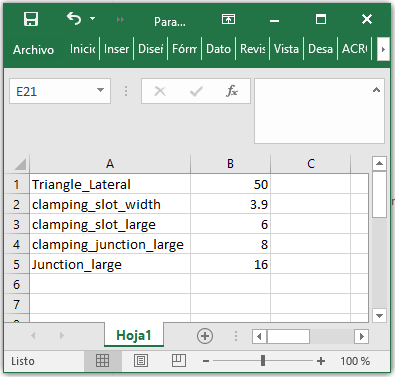
The file is Parameter.xlsx in excel to enter the parameters:
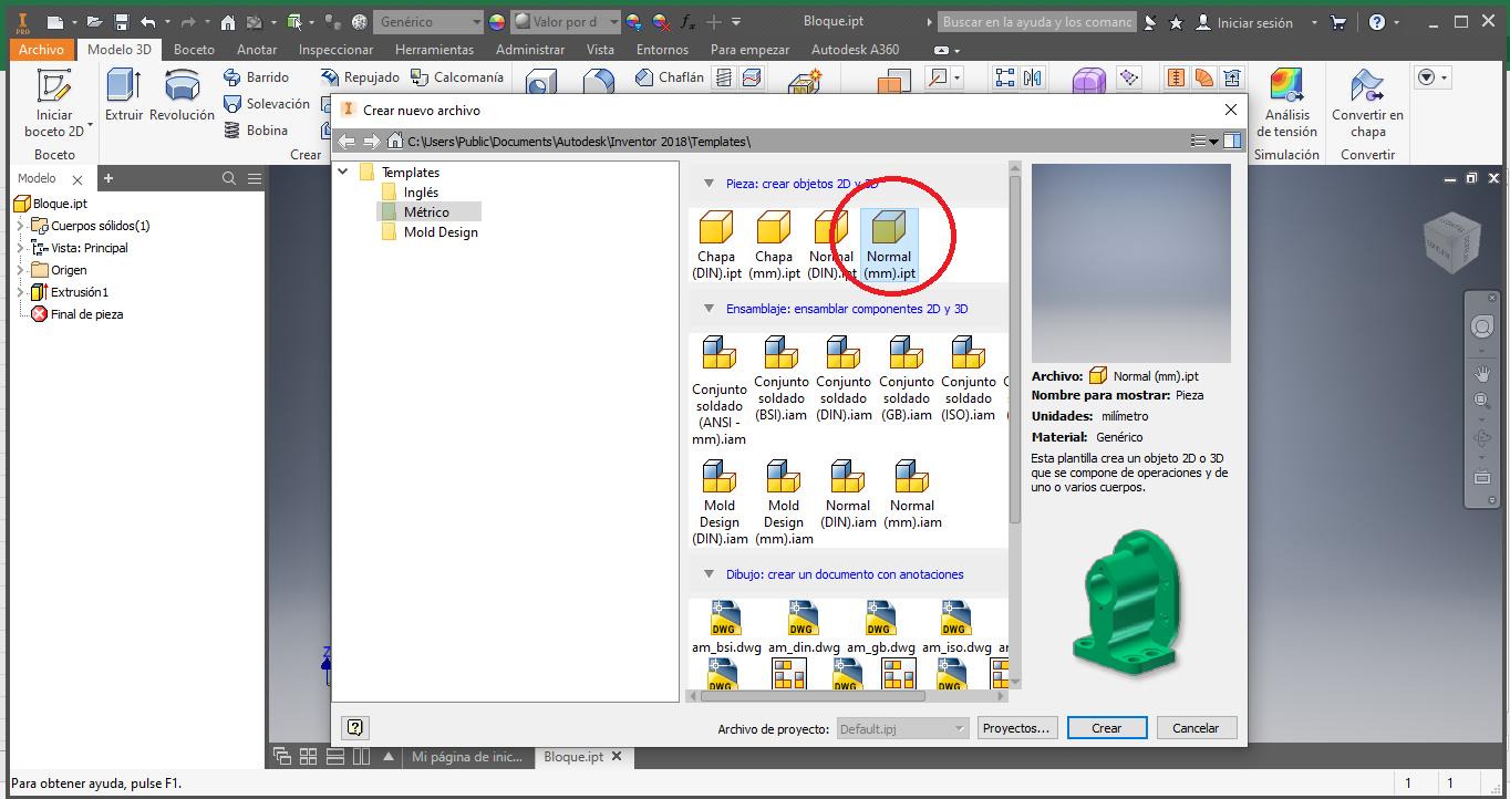
We start a new piece in 3D:
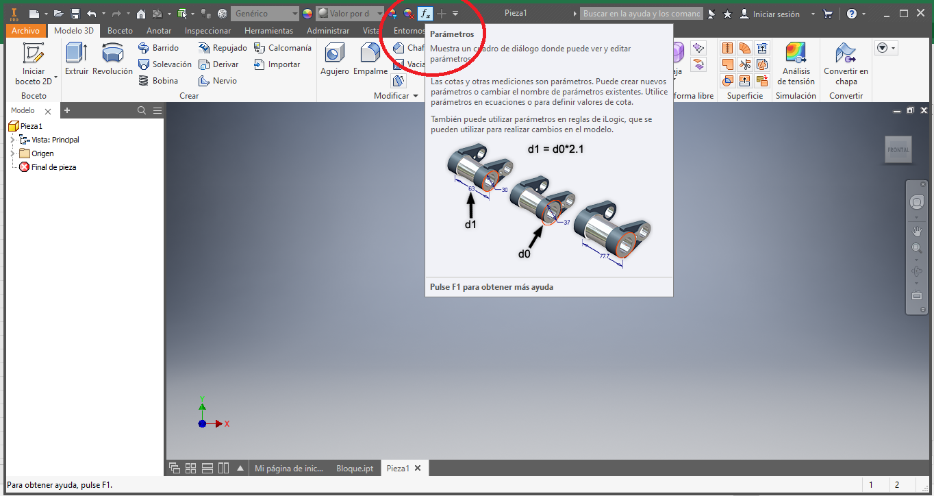
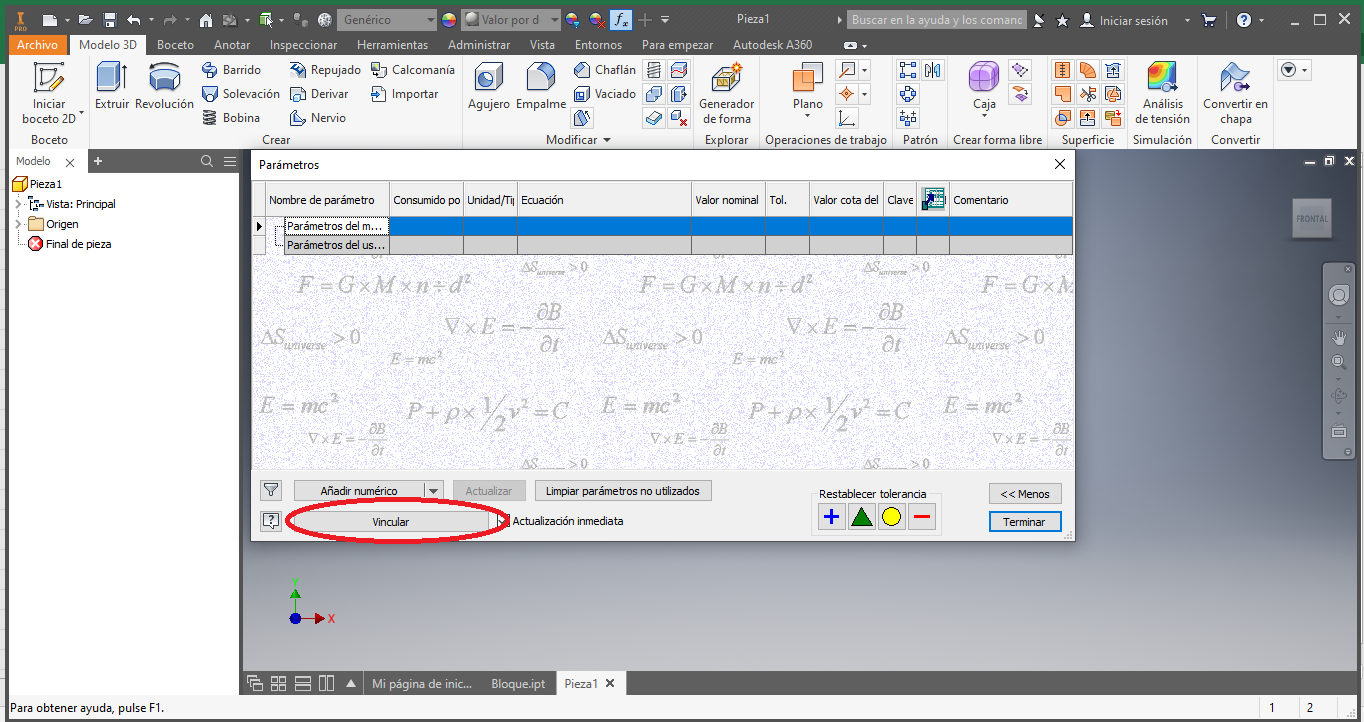
Before starting to design we add the parameters of the file in excel to the Autodesk Inventor design, we look for the parameters icon in the software, it is found in the upper part with the fx symbol
In the window that we have, we click on the link button
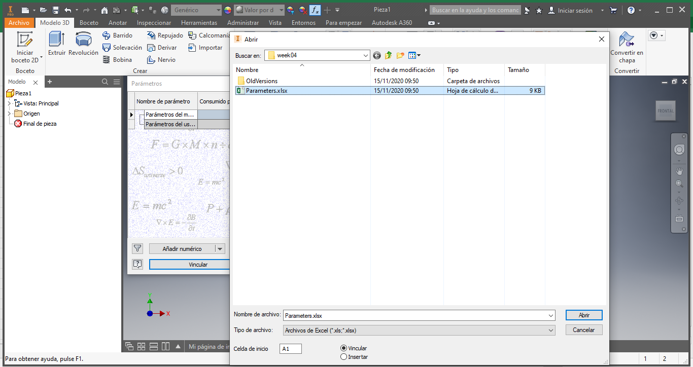
In the window that appears, we select the file in excel and click on Open
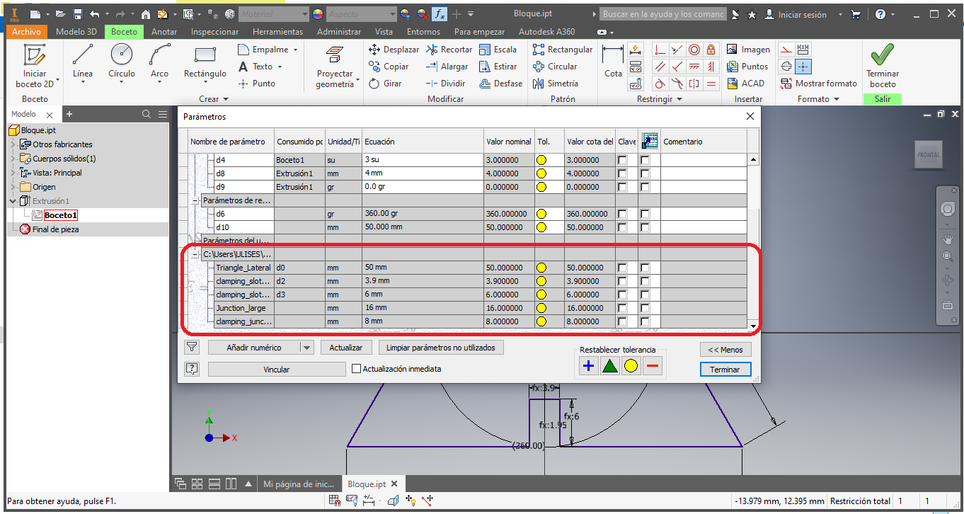
This action will add the list of parameters defined in the file in excel:
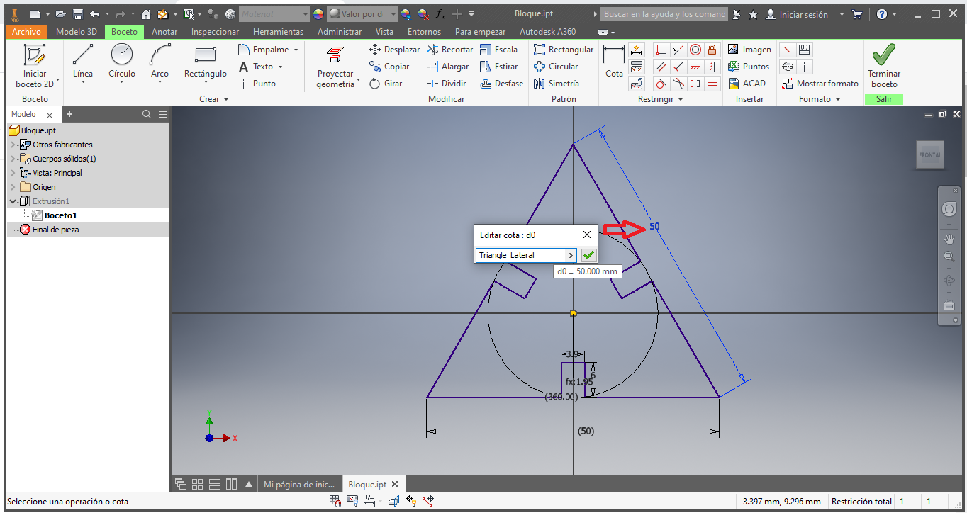
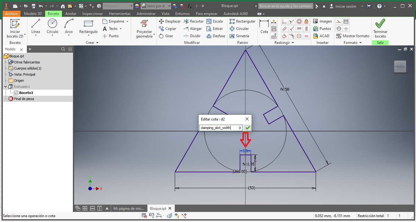
We start to design using the previously defined parameters, in this case the lateral length of the triangle:
Now we add the width of the slot:
Then the depth of the groove:
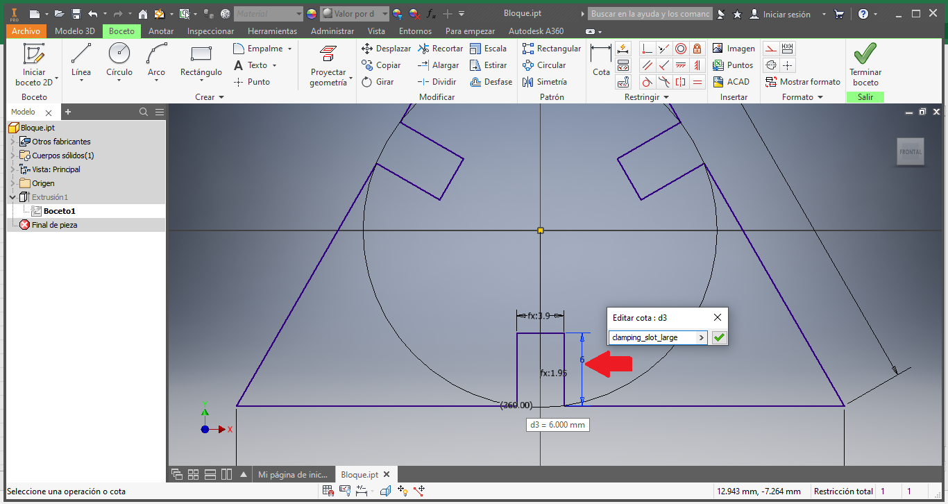
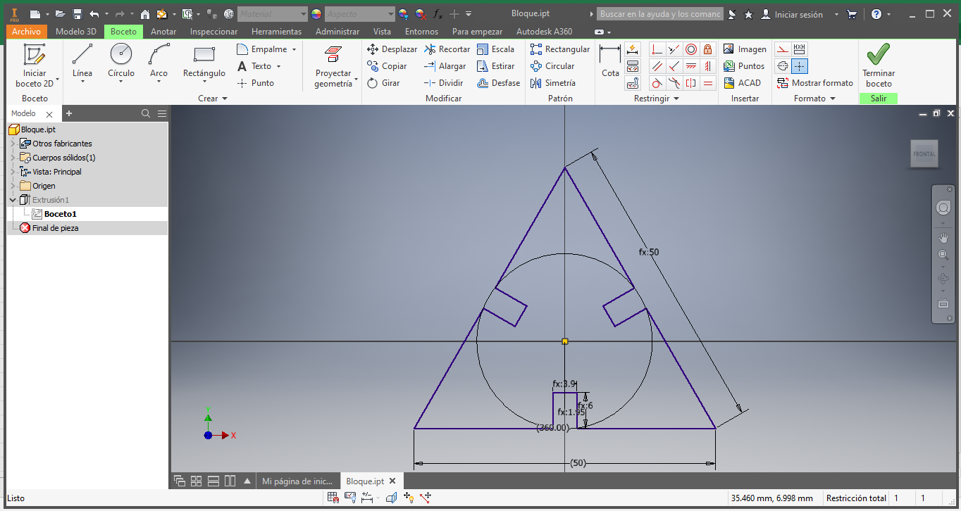
Finally we have the design parameterized by the data in the file in Excel:
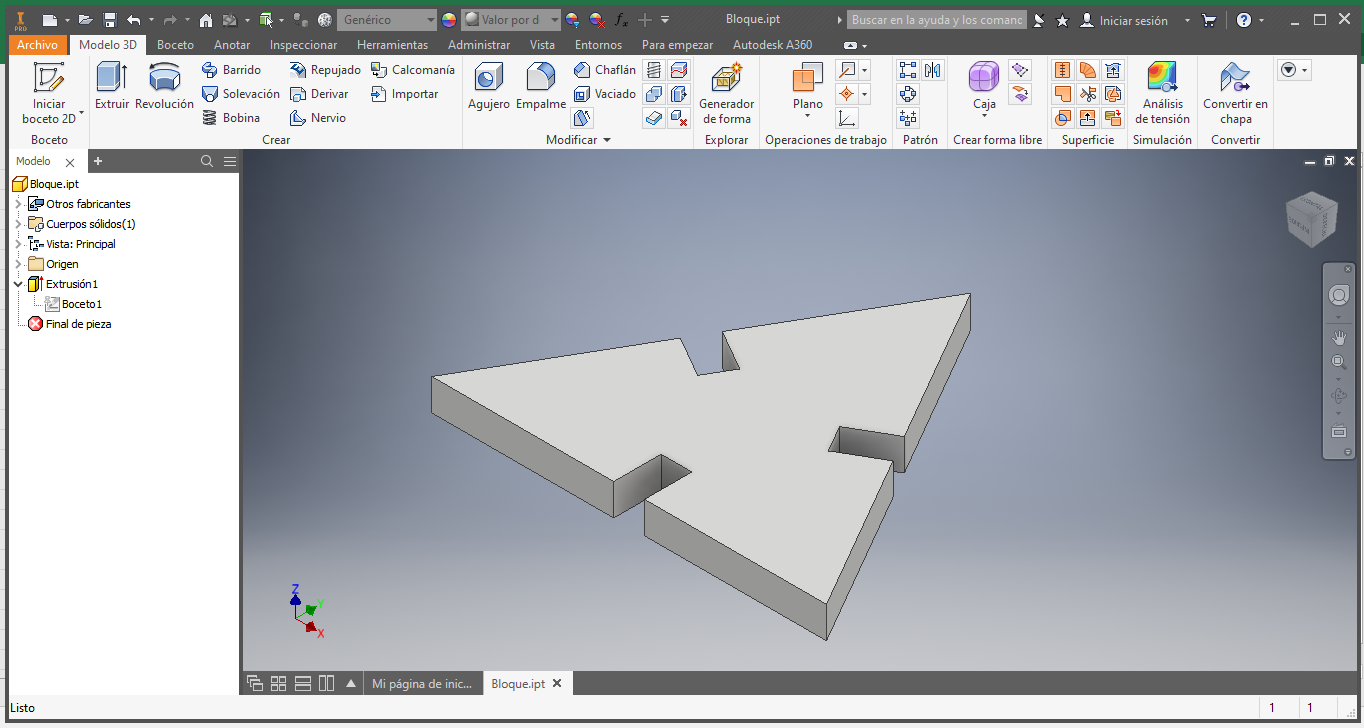
We extrude the design to obtain the following 3D object, which would be our first parametric piece:
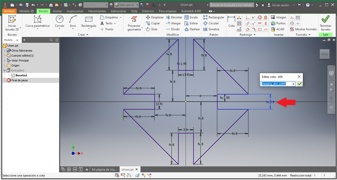
Now we carry out the same sequence for the second parametric part, in this case we define the depth of the groove:
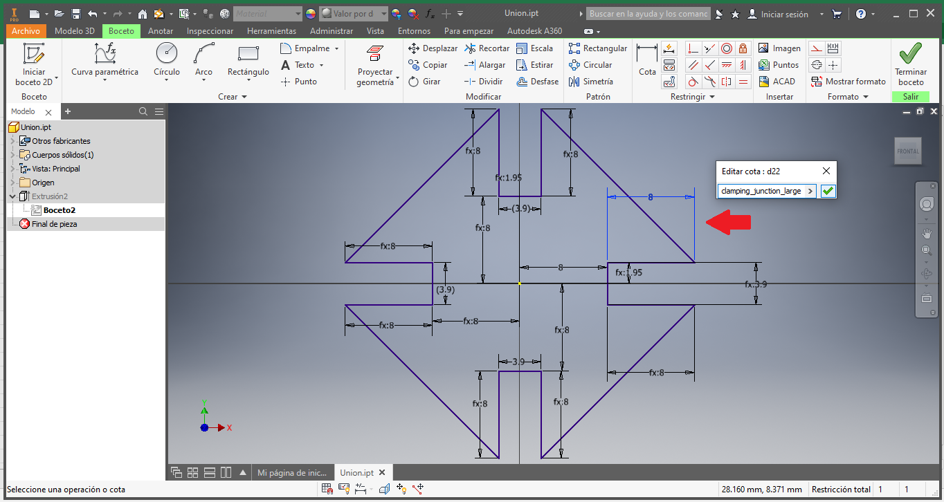
Now in slot width:
Then the length of the connecting piece that is the second piece of the parametric kit:
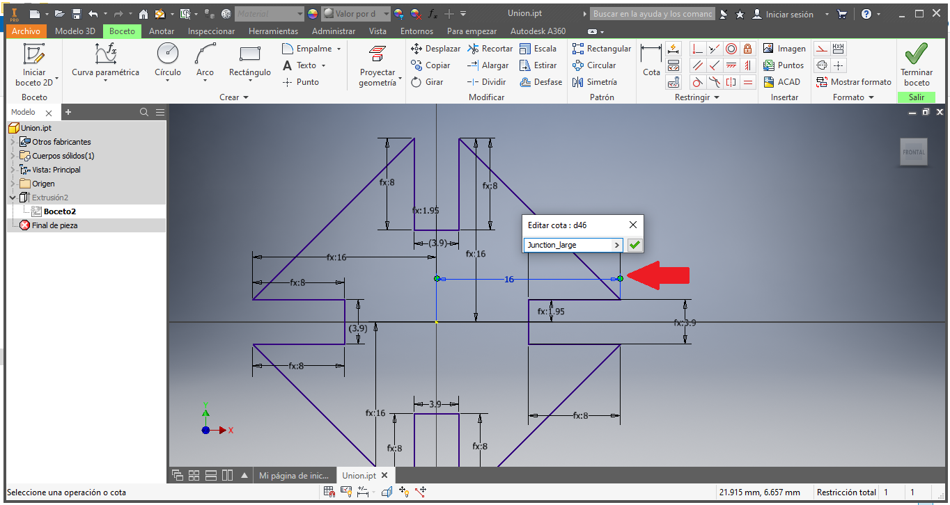
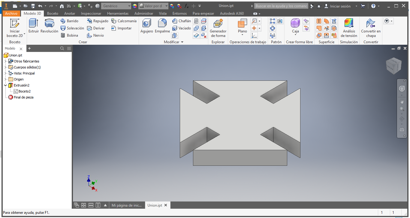
Finally we have the 3D piece that will serve us to join the other pieces:
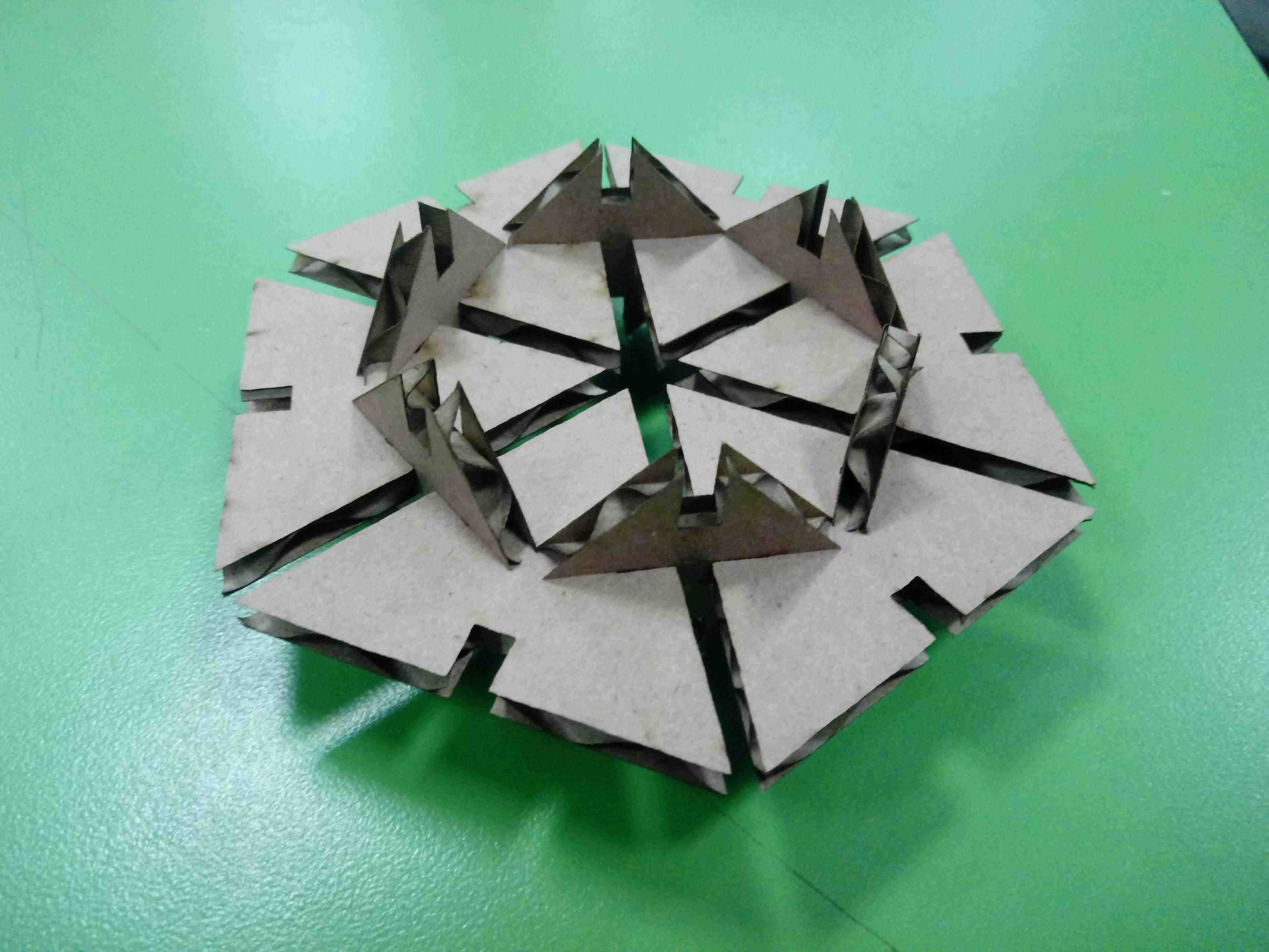
Parametric Construction Kit
I create a piece to join between them
I use cardboard to create, in my case I use the parameters of machine
- Speed: 60mm/s
- Power: 29%
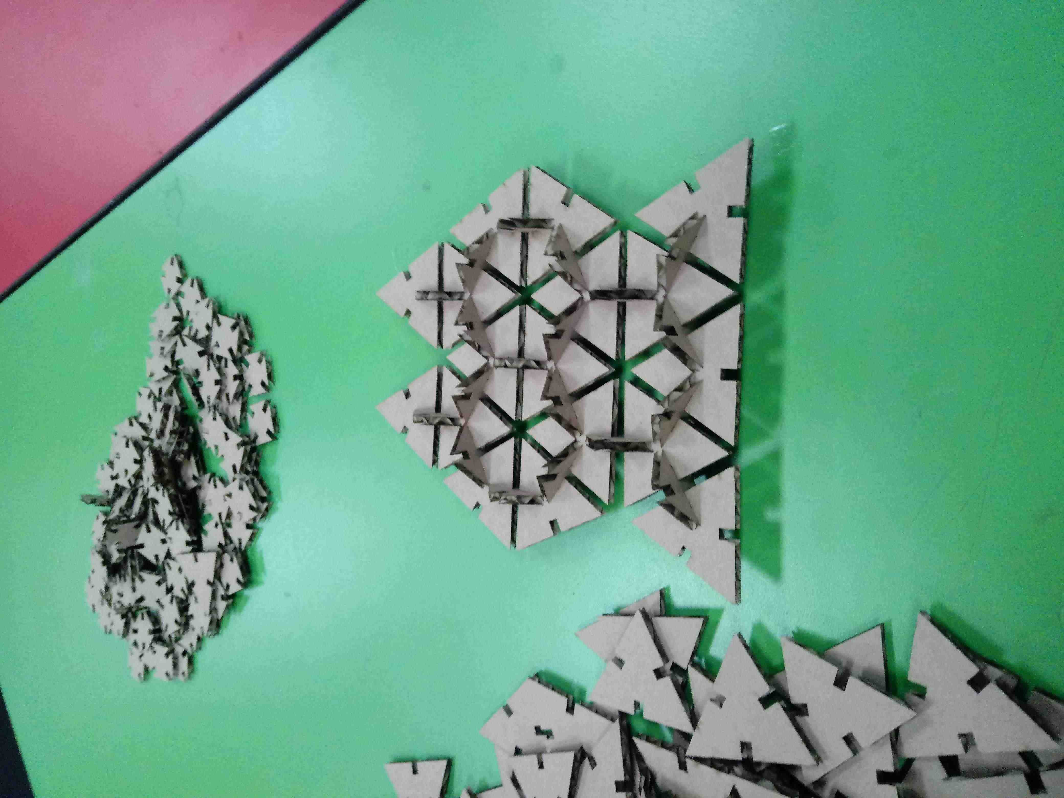
I join the pieces together and they make a good bond
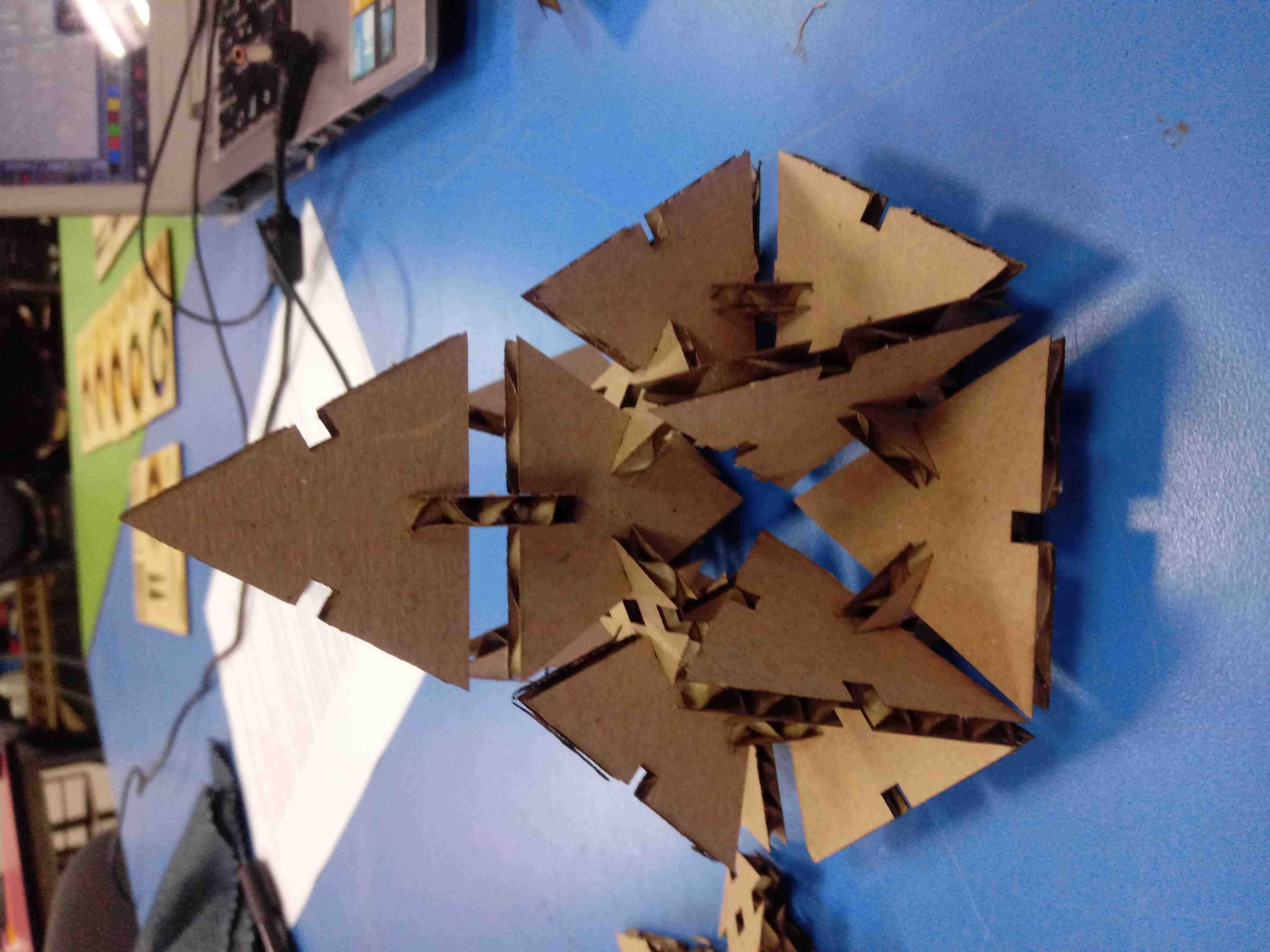
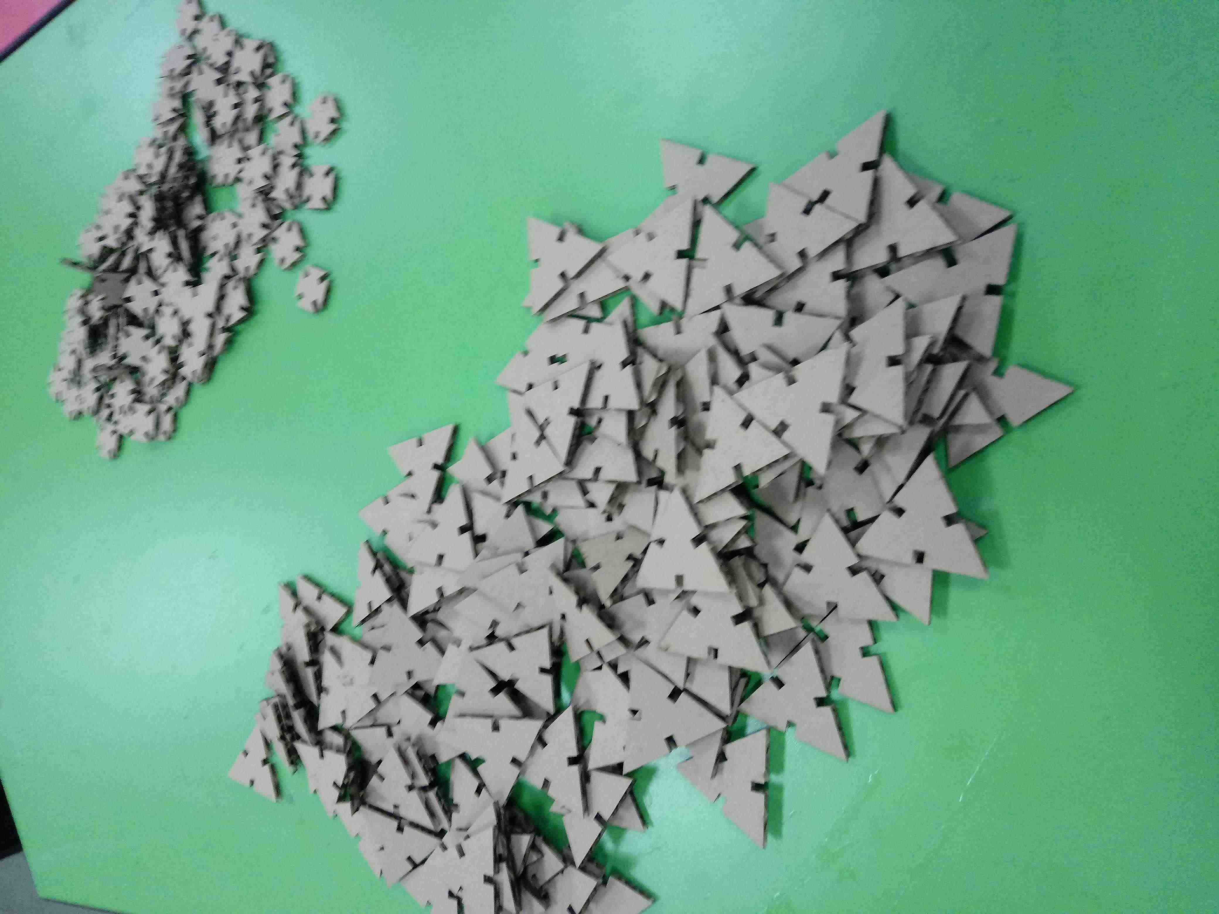
I cut more pieces to use in my prototypes
These are my block to create any object, similar to the lego function:
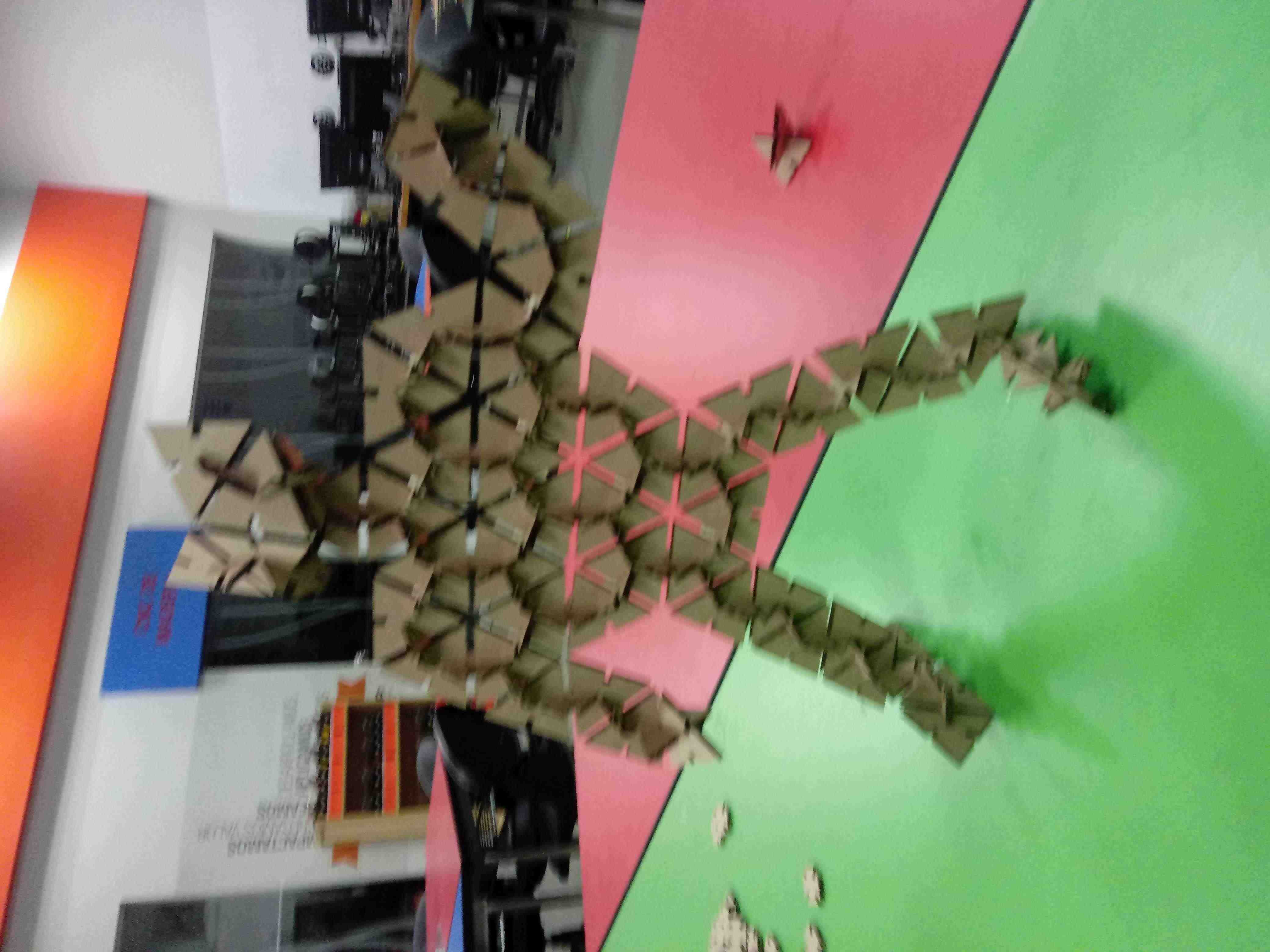
First I build a ship of UFO:
Second I build an airship battle:
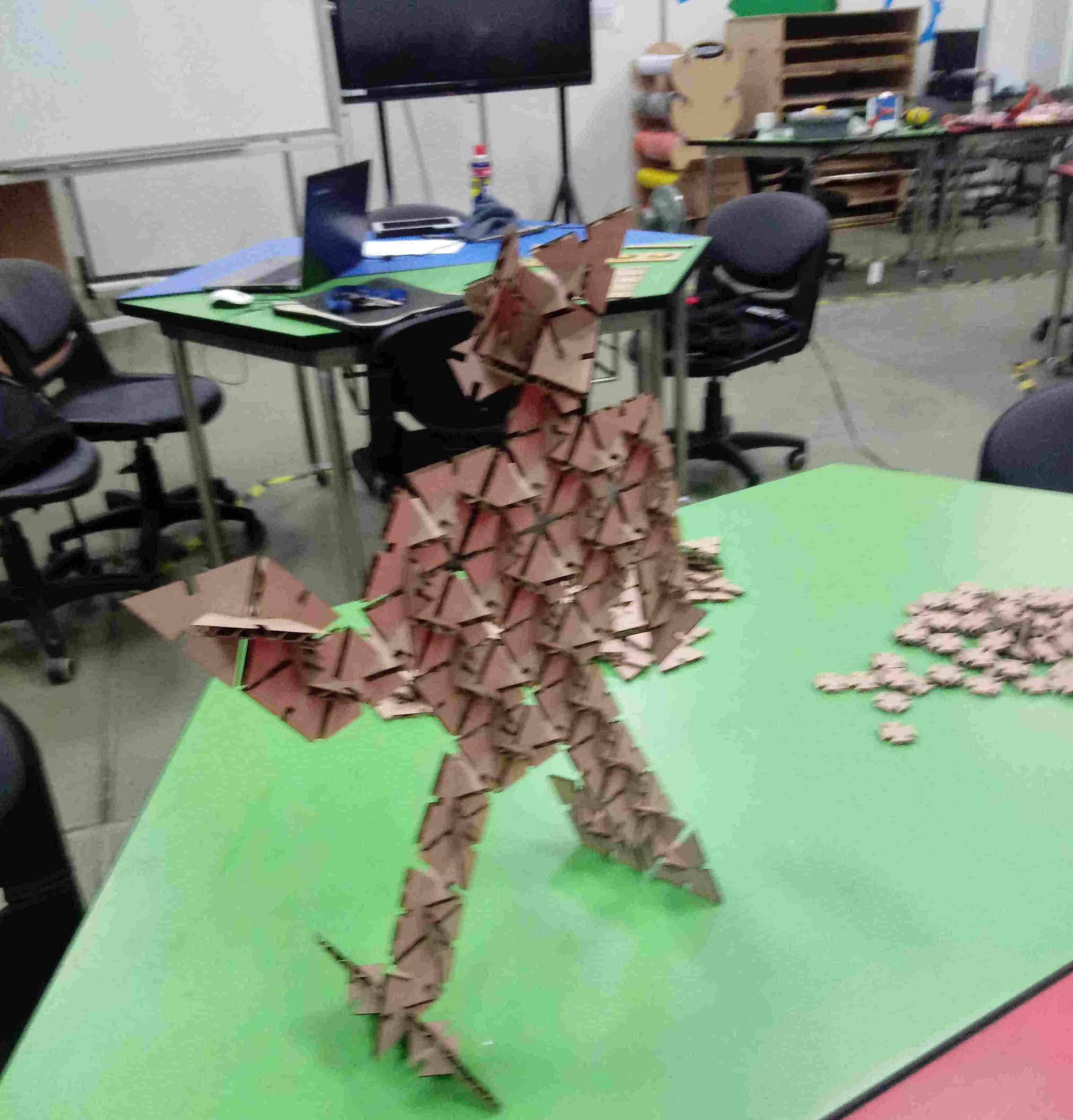
Finally I create a HUMAN
Nice human, but the structure is very weak due to the way of construction, is that the human figure has unreinforced joints such as the hip and shoulder:
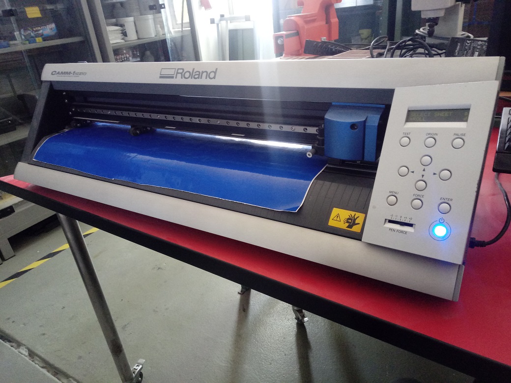
Vinyl Cutting Machine
- To work the Fablab has a CAMM-1 Servo GX-24 from ROLAND with a computer to edit the file to cutting in CutStudio Software:
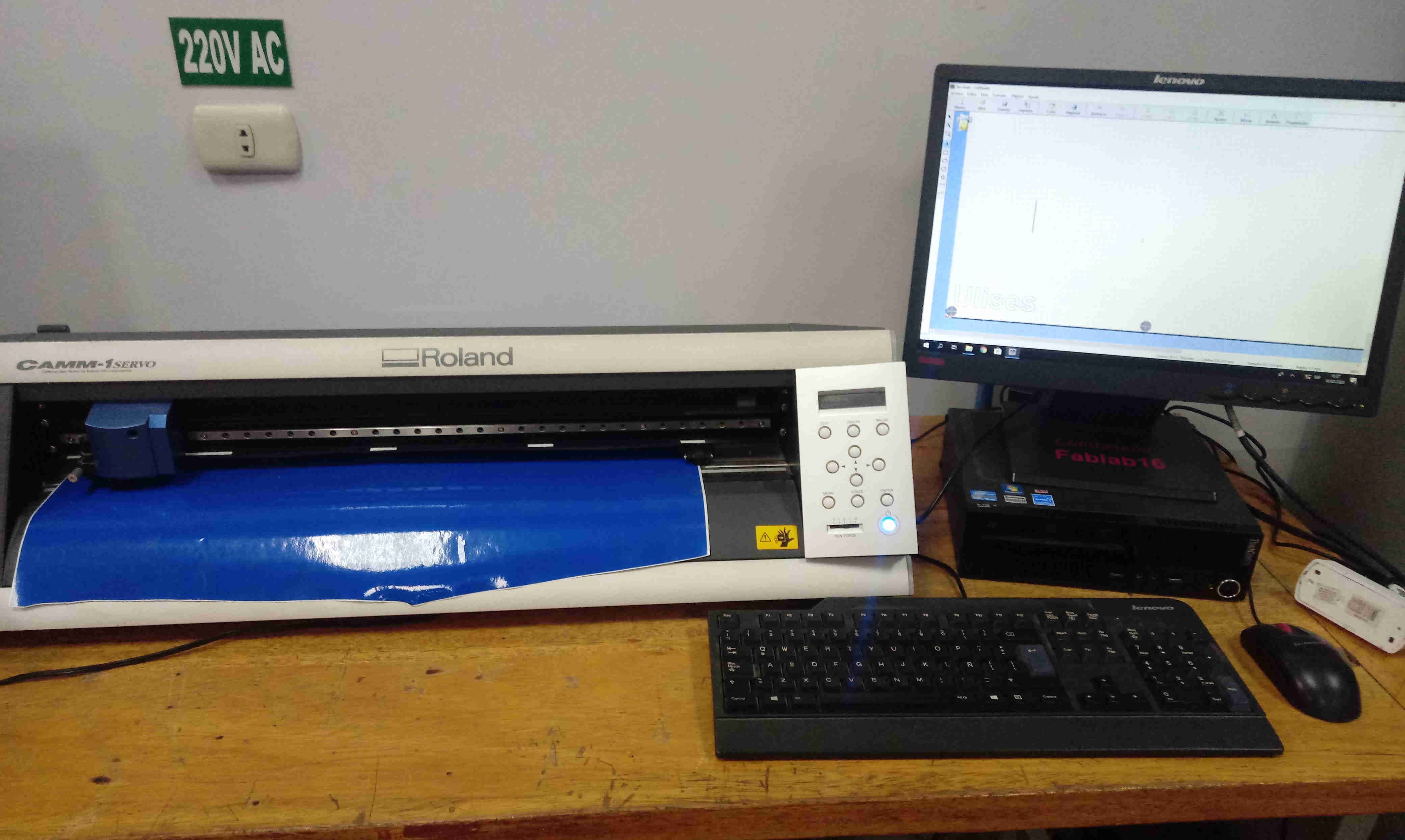
I work with Fablab Tecsup’s logo to transfer to glass:

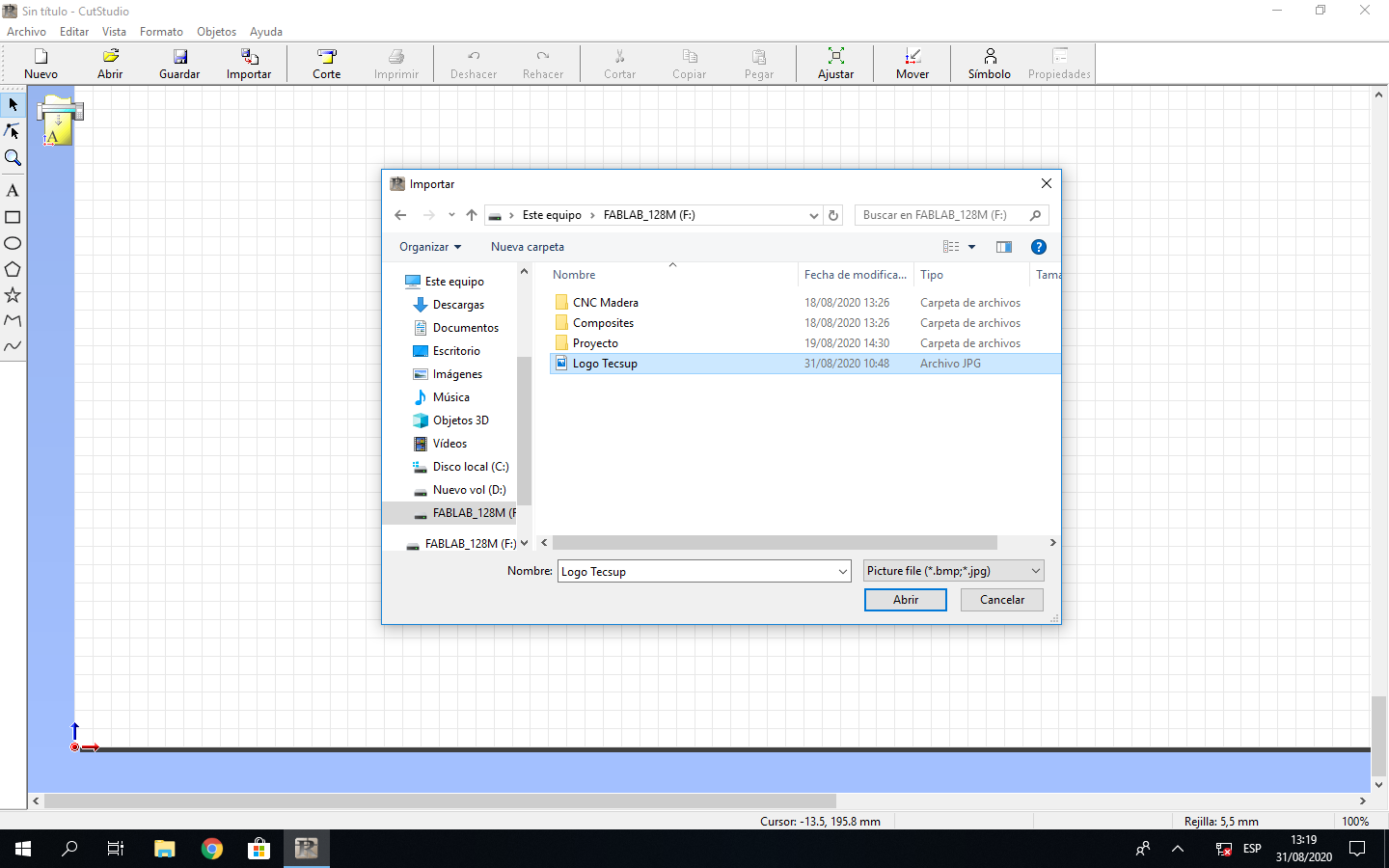
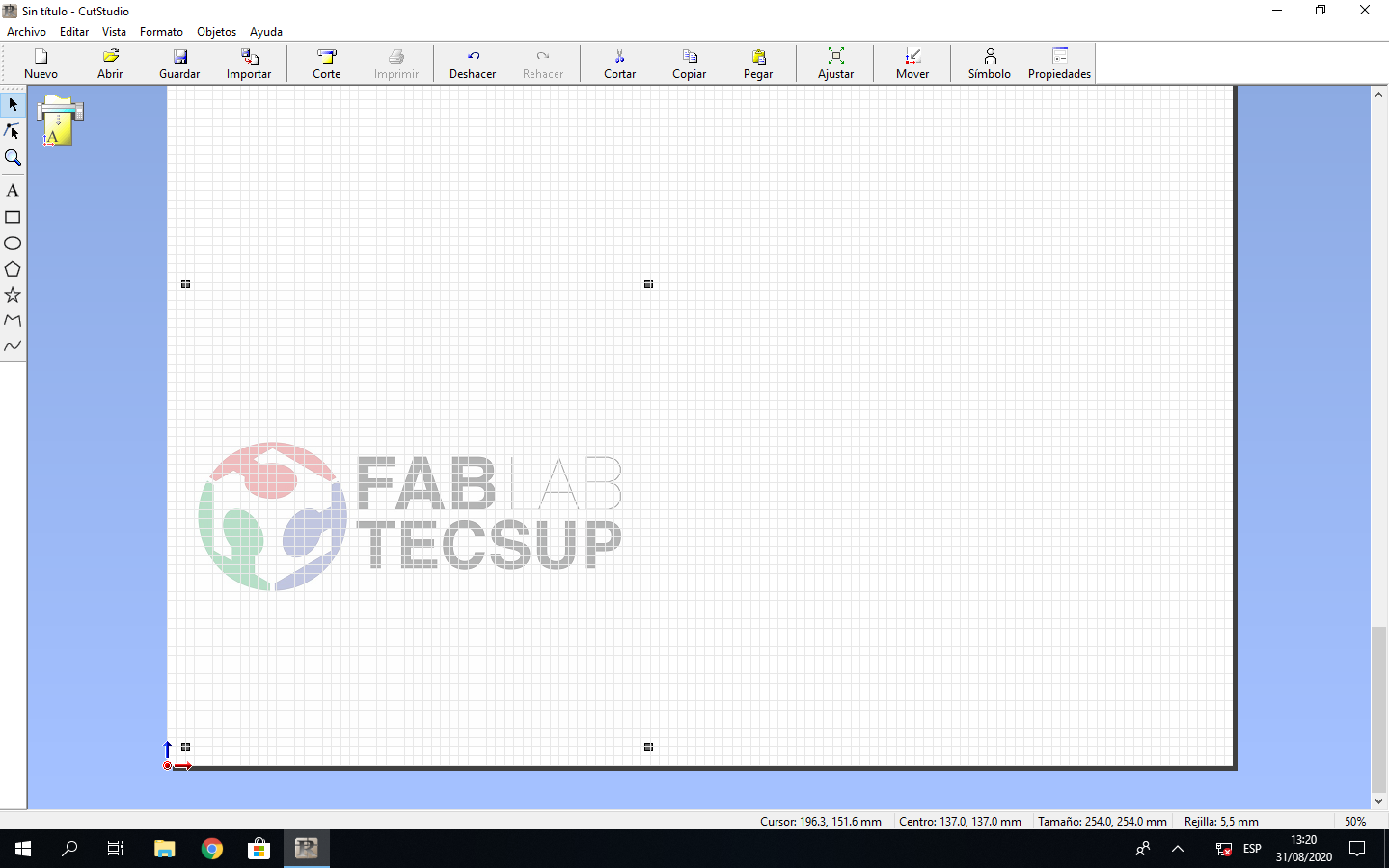
I execute the CUTSTUDIO software in the computer, and import the file of logo:
This is an image with colored parts, so I extract its outline
I click right over the imagea and choose the image outline option:
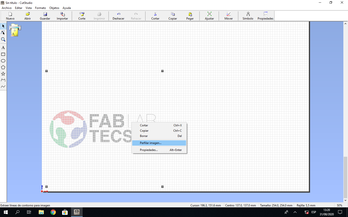
I choose the option of Extract the outline button:
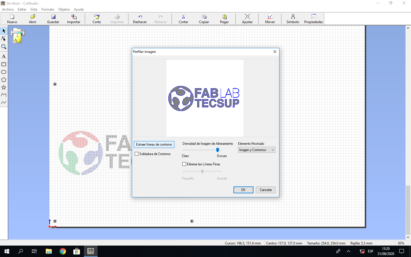
This processed image has 2 layer, the original image and the outline:
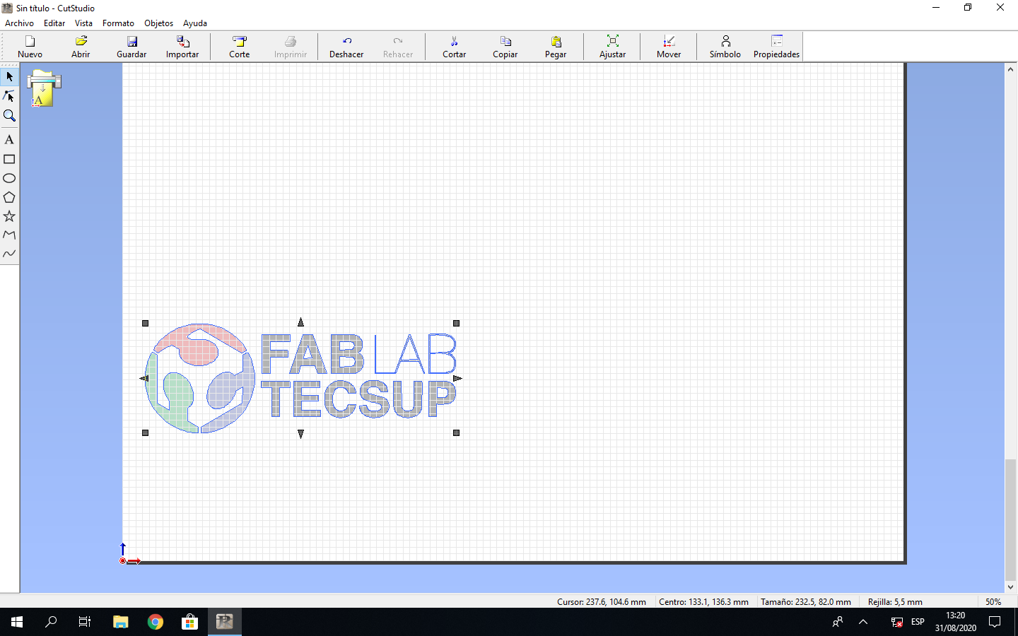
I choose the outlines and separate of the original:
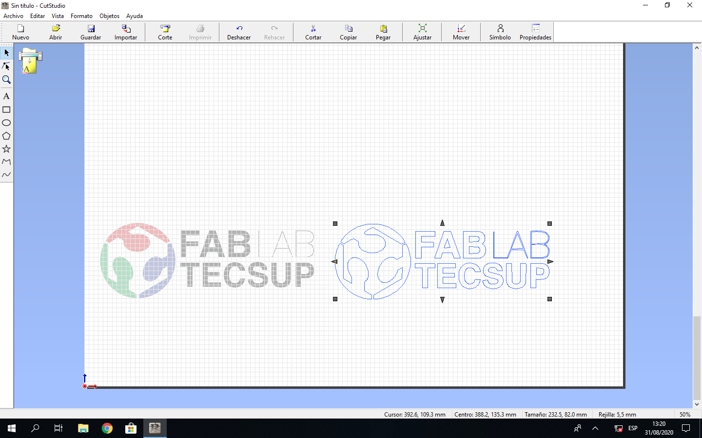
I erase the original image and I colocate the outline image to cutting process:
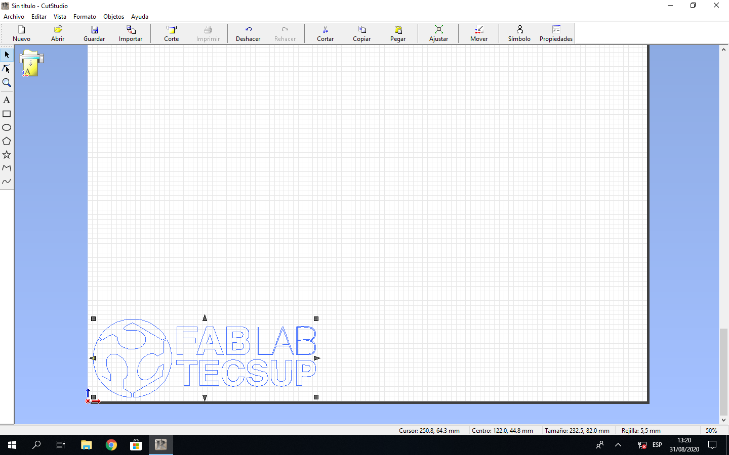
The cutting is similar to print process, so I choose the print option:
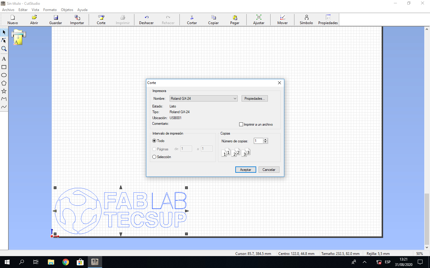
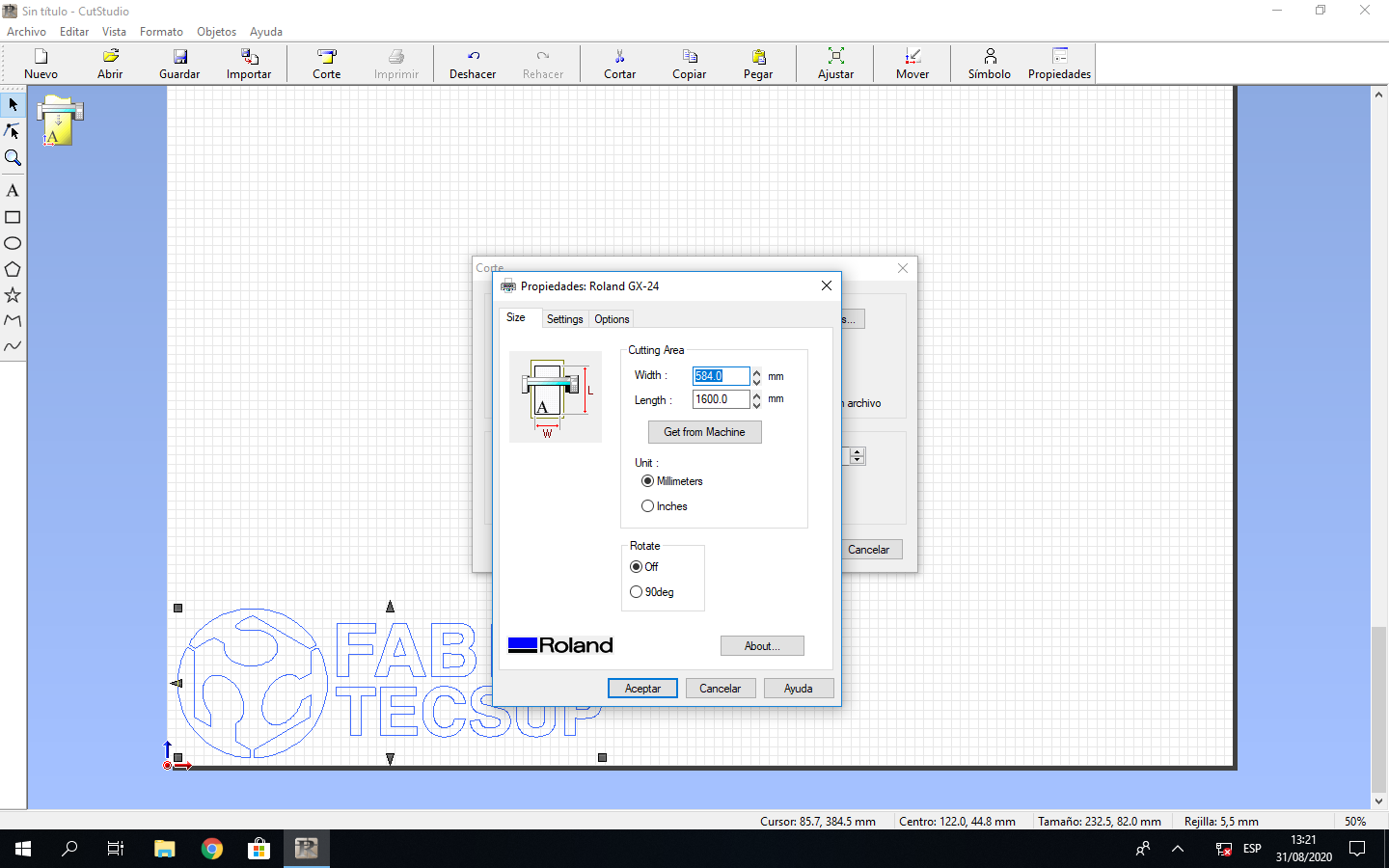
I get from machine size to work, select the milimeters to work and accept the cutting process:
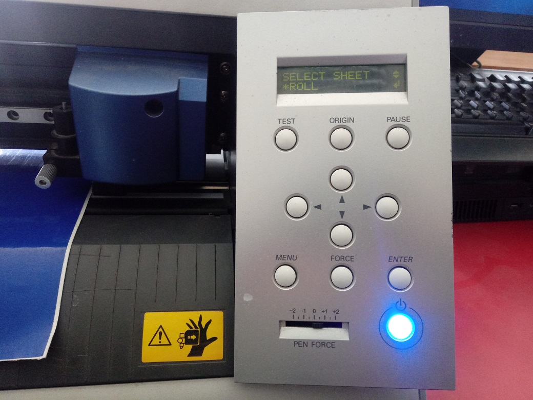
I turn on the cutting machine, configurate the parameter to cut and send the cutting file from CUTSTUDIO software:
The machine start the cutting process and after some minutes the work is finish:
So I use transfer paper to move the cutted image to glass:
Designed Files
| Description | Files |
|---|---|
| - Scalimeter Design | Escalerimetro.cdr |
| - Pattern Engraving | Prueba_MDF.cdr |
| - Parametric Block | Bloque.ipt |
| - Parametric Junction | Union.ipt |
| - Parameters | Parameters.xlsx |
| - Cutting File | Patron.cdr |
| - Logo Vinyl File | Logo.jpg |