15. Networking and Communications
Individual Assignment:
- Design, build, and connect wired or wireless node(s) with network or bus addresses
Group Assignment:
- Send a message between two projects
INDIVIDUAL ASSIGNMENT:
This week I worked on design, build and connect wireless by IOT Plataform.
When we word with IOT we use the following structure:
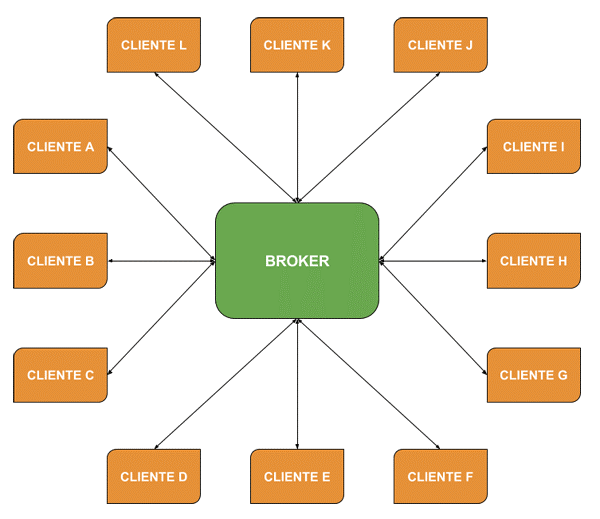
The Broker is the central part of the architecture and all messages go through it.
MQTT publish / subscribe architecture:
It is an event-based architecture. Each message is sent to recipients who have subscribed to a specific publication. The Broker is in charge of distributing the messages to the receivers.
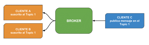
The topic:
It is the subject where the recipients subscribe to receive the message. You will see a typical communication to understand the concept of publish / subscribe architecture. A customer subscribes to a topic that is like the topic, to whom the message is directed. We can think of it as the subject of an email. A message has no specific recipient, there can be one, many or none.
ESP8266
It is a very low cost Wi-Fi module, which allows you to connect wireless networks and program them with the Arduino IDE. Produced by the Espressif company. In its production there are currently several modules, based on said microcontroller.
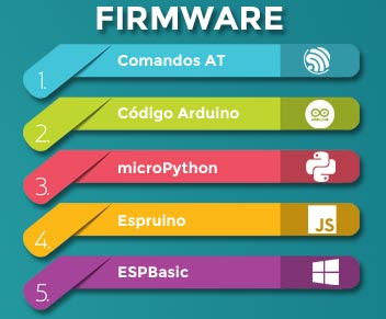
The ESP8266 is a microcontroller and as such it can do the same functions as an Arduino board. Of course, it has its limitations. The main features of the ESP8266 are as follows: • 32-bit RISC CPU: Tensilica Xtensa LX106 running at 80 MHz (which can be overclocked at 160MHz if required) • 64 KiB of RAM for instructions and 96 KiB of RAM for data • IEEE 802.11 b / g / n Wi-Fi • 16 GPIO pins • SPI and I2C • UART on dedicated pins (used for chip programming) • A 10 bit Analog-Digital Converter (ADC)
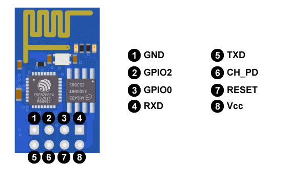
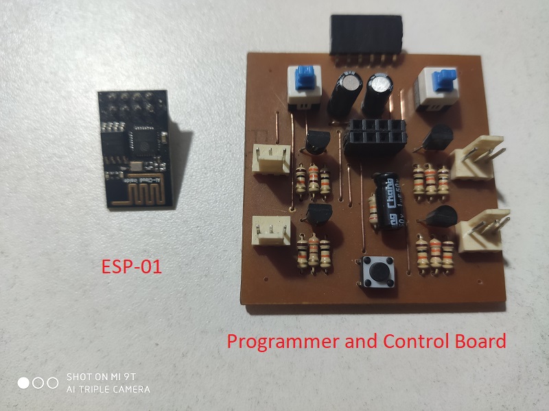
ESP-01 THE MICROCONTROLLER PLATE The ESP-01 card is the model most used for its low cost and high performance, the figure shows the parts of it:
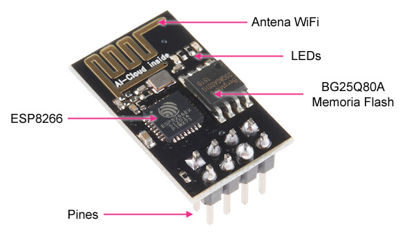
• ESP8266: It is the microcontroller of the ESP-01 module. • Pins: Where we will connect the power, sensors and program transmission. • BG25Q80A: It is the flash memory where the programs or sketchs reside. The ESP8266 does not have this type of memory and therefore is a separate chip. • LEDs: They inform us if it is on or not and the data transmission (Tx and Rx). • The WiFi antenna to connect to a network / Internet.
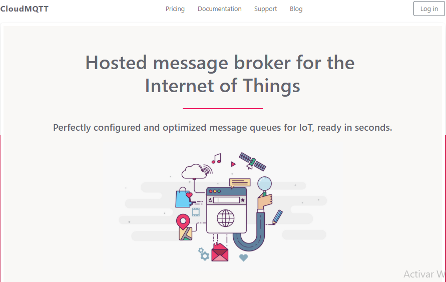
CloudMQTT
CloudMQTT is a perfect solution for “Internet of Things” messages between low-power sensors or mobile devices like phones, embedded computers, or microcontrollers like the Arduino. CloudMQTT automates every part of configuring and running your mosquitto messaging agent. It allows the team to focus on building their good product and leaves server management and supervision to the CloudMQTT web service.
To configure and obtain an MQTT server on the web, I work with the service of https://www.cloudmqtt.com/, in which we can have up to 5 variables for free.
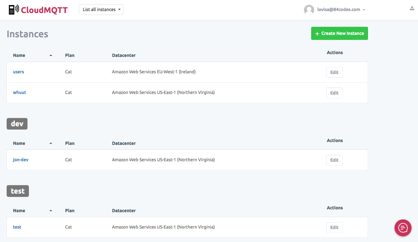
First you LOGIN:
Next I have created an instance for our project, in this case an instance is like a project in the service.
Next you create the User’s account
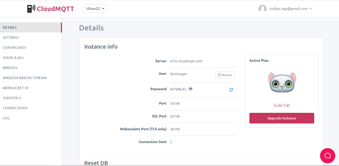
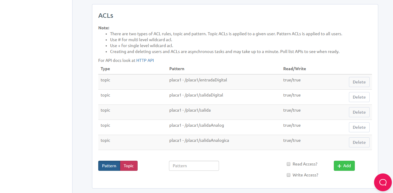
Next you create the topic on account, the topics are the variables that you have in the MQTT server that would be the brokers, these would be the variables that can be publish and subscribe
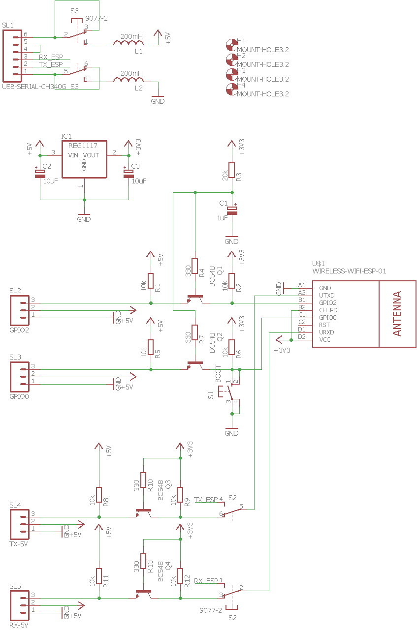
Schematic and Board
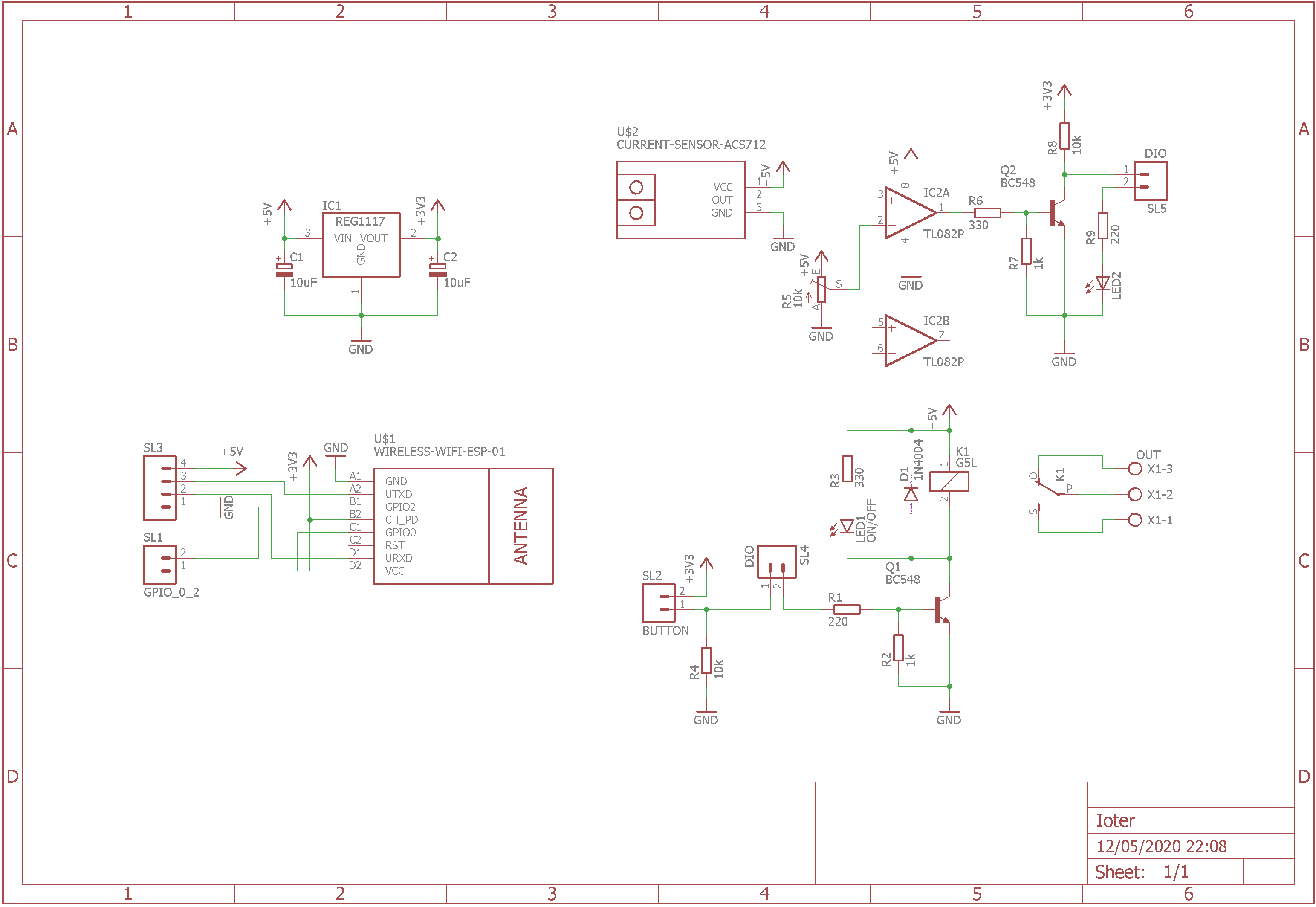
The circuit design was done in Autodesk Eagle.

The design was worked with a through-hole mounting component, for the reason of having the components but we cannot buy them due to the restrictions of the 2020 pandemic.
The schematic with the ESP-01
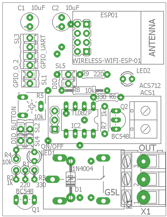
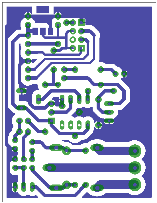
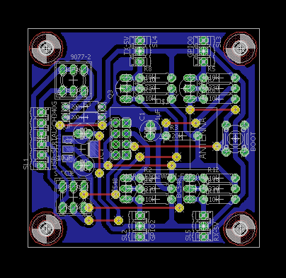
In this image we can see the location of the components:
In this image we can see the pads and bridges at the top. that will help us to connect having the plate on one side, with the bottom
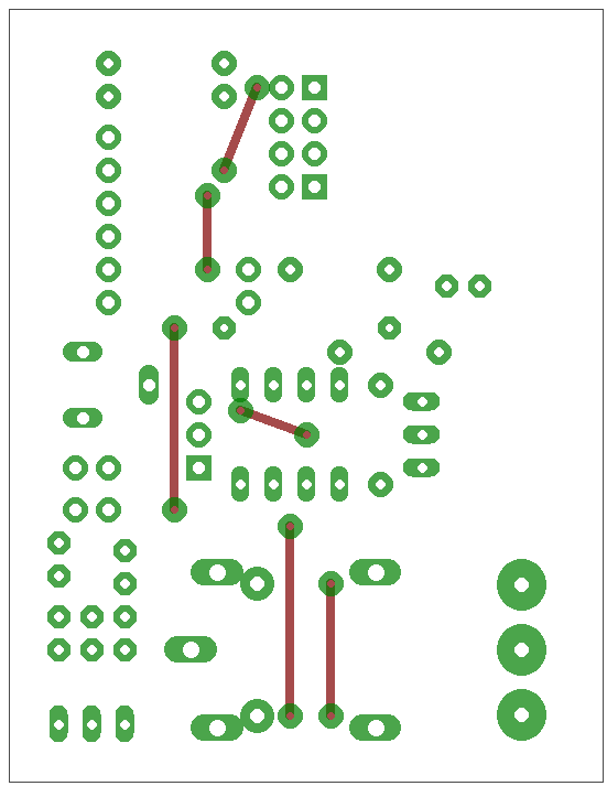
In this image we can see the clues at the bottom.
The manufacturing procedure will be carried out with a manual method, which would be using a laser ink printing and transferring with an iron towards the copper plate, and using ferric acid to obtain in the end only the tracks on the copper plate.
Programming ESP-01
The ESP-01 programming procedure was performed with the Arduino IDE and a library of PubSubClient, which we have to add to Arduino IDE with the library manager.
The preparation of the Arduino IDE to work with the ESP8266 we have detailed in Week 9 of Embedded programming in the 3th part.
The program is the following:
#include <ESP8266WiFi.h>
#include <PubSubClient.h>
//-------------------VARIABLES GLOBALES--------------------------
int contconexion = 0;
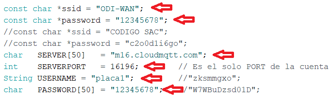
const char *ssid = "ODI-WAN";
const char *password = "12345678";
//const char *ssid = "CODIGO SAC";
//const char *password = "c2o0d1i6go";
char SERVER[50] = "m16.cloudmqtt.com";
int SERVERPORT = 16196; // Es el solo PORT de la cuenta
String USERNAME = "placa1"; //"zksmmgxo";
char PASSWORD[50] = "12345678"; //"W7WBuDzsd01D";
unsigned long previousMillis = 0;
char charPulsador [15];
String strPulsador;
String strTexto;
String strPulsadorUltimo;
char PLACA[50];
char valueStr[15];
String strtemp = "";
char TEMPERATURA[50];
char PULSADOR[50];
char SALIDADIGITAL[50];
char SALIDAANALOGICA[50];
bool pulsador_ant;
bool estado_led;
#define pin_relay 3
#define pin_boton 0
//--------------------------------------------------------------
WiFiClient espClient;
PubSubClient client(espClient);
//------------------------CALLBACK------------------------------
void callback(char* topic, byte* payload, unsigned int length) {
char PAYLOAD[5] = " ";
for (int i = 0; i < length; i++) {
PAYLOAD[i] = (char)payload[i];
}
if (String(topic) == String(SALIDADIGITAL)) {
if (payload[1] == 'N'){
digitalWrite(pin_relay, HIGH);
estado_led = HIGH;
strTexto = "Consumiendo";
strTexto.toCharArray(valueStr, 15);
client.publish(SALIDAANALOGICA, valueStr);
}
if (payload[1] == 'F'){
digitalWrite(pin_relay, LOW);
estado_led = LOW;
strTexto = "No Consume ";
strTexto.toCharArray(valueStr, 15);
client.publish(SALIDAANALOGICA, valueStr);
}
}
}
//------------------------RECONNECT-----------------------------
void reconnect() {
uint8_t retries = 3;
// Loop hasta que estamos conectados
while (!client.connected()) {
// Crea un ID de cliente al azar
String clientId = "ESP8266Client-";
clientId += String(random(0xffff), HEX);
// Attempt to connect
USERNAME.toCharArray(PLACA, 50);
if (client.connect("", PLACA, PASSWORD)) {
client.subscribe(SALIDADIGITAL);
client.subscribe(SALIDAANALOGICA);
} else {
// espera 5 segundos antes de reintentar
delay(5000);
}
retries--;
if (retries == 0) {
// esperar a que el WDT lo reinicie
while (1);
}
}
}
//------------------------SETUP-----------------------------
void setup() {
pinMode(13, OUTPUT); // D7 salida analógica
analogWrite(13, 0); // analogWrite(pin, value);
pinMode(pin_relay, FUNCTION_3);
pinMode(pin_relay, OUTPUT); // D6 salida digital
digitalWrite(pin_relay, LOW);
// Entradas
pinMode(14, INPUT); // D5
pinMode(pin_boton, INPUT); // D0
// Conexión WIFI
WiFi.begin(ssid, password);
while (WiFi.status() != WL_CONNECTED and contconexion <50) { //Cuenta hasta 50 si no se puede conectar lo cancela
++contconexion;
delay(500);
}
if (contconexion <50) {
//para usar con ip fija
IPAddress ip(192,168,43,140);
IPAddress gateway(192,168,43,1);
//IPAddress ip(192,168,0,120);
//IPAddress gateway(192,168,0,1);
IPAddress subnet(255,255,255,0);
WiFi.config(ip, gateway, subnet);
}
else {
}
client.setServer(SERVER, SERVERPORT);
client.setCallback(callback);
String temperatura = "/" + USERNAME + "/" + "temperatura";
temperatura.toCharArray(TEMPERATURA, 50);
String pulsador = "/" + USERNAME + "/" + "pulsador";
pulsador.toCharArray(PULSADOR, 50);
String salidaDigital = "/" + USERNAME + "/" + "salida";
salidaDigital.toCharArray(SALIDADIGITAL, 50);
String salidaAnalogica = "/" + USERNAME + "/" + "salidaAnalogica";
salidaAnalogica.toCharArray(SALIDAANALOGICA, 50);
}
//--------------------------LOOP--------------------------------
void loop() {
if (!client.connected()) {
reconnect();
}
client.loop();
unsigned long currentMillis = millis();
if (currentMillis - previousMillis >= 10000) { //envia la temperatura cada 10 segundos
previousMillis = currentMillis;
int analog = analogRead(17);
float temp = analog*0.322265625;
strtemp = String(temp, 1); //1 decimal
strtemp.toCharArray(valueStr, 15);
client.publish(TEMPERATURA, valueStr);
}
if (pulsador_ant!=digitalRead(pin_boton)){
pulsador_ant = digitalRead(pin_boton);
if(digitalRead(pin_boton)==LOW){
delay(200);
if(digitalRead(pin_boton)==LOW){
if (estado_led){
strPulsador = "OFF";
estado_led = LOW;
} else {
strPulsador = "ON";
estado_led = HIGH;
}
}
}
}
if (strPulsador != strPulsadorUltimo) { //envia el estado del pulsador solamente cuando cambia.
strPulsadorUltimo = strPulsador;
strPulsador.toCharArray(valueStr, 15);
client.publish(SALIDADIGITAL, valueStr);
}
}
In order to modify it and use it in your tests, you have to modify the connection WIFI network and its password, in addition to the server data to use, in my case it will be cloudMQTT.
The topic we use to control the 220VAC line on or off is as follows:
- /placa1/salida
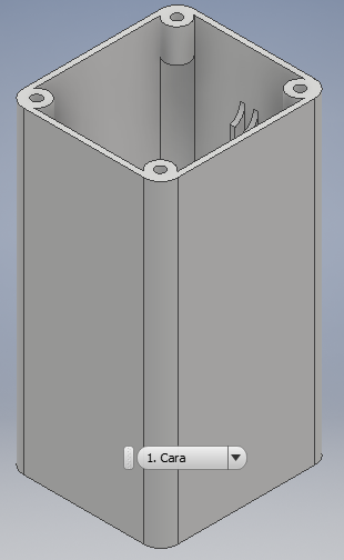
The box
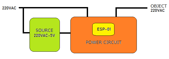
Design the box of the project, it must have a good spacing since it will contain the 220VAC to 5VDC adapter source to power the card, in addition to the 220VAC input and output connector:
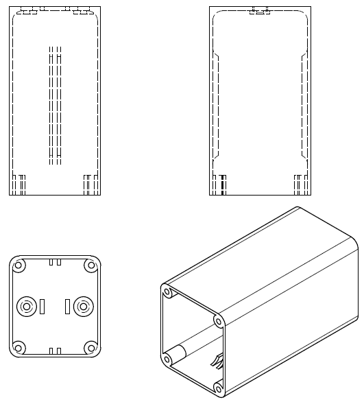
We can see the image of the box in isometric or 3D:
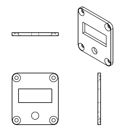
We can see the image of the boc cover:
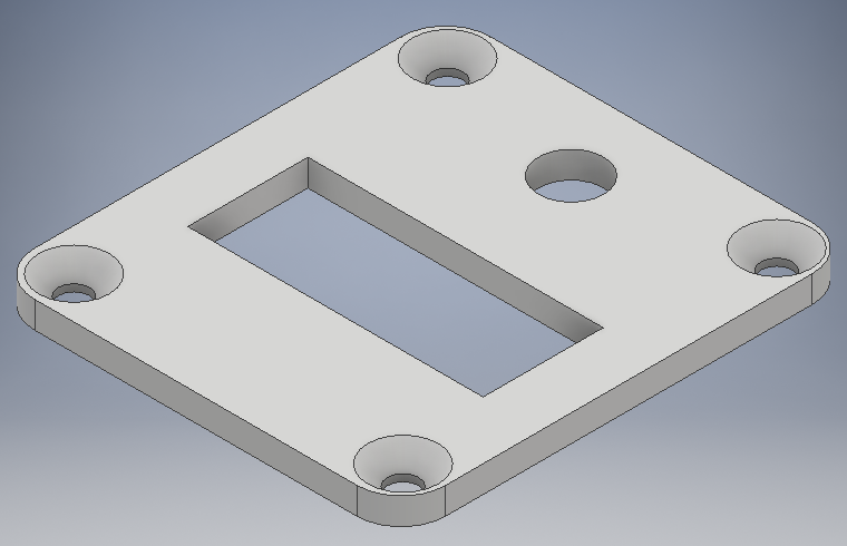
3D box view of the box cover, in Autodesk inventor software:
Assembly
The printing of the parts was carried out with the same steps explained in the steps of week 6 of 3D Scanning and Printing, for which we have the printed parts:
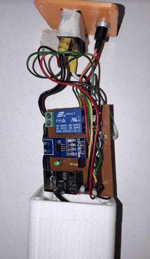
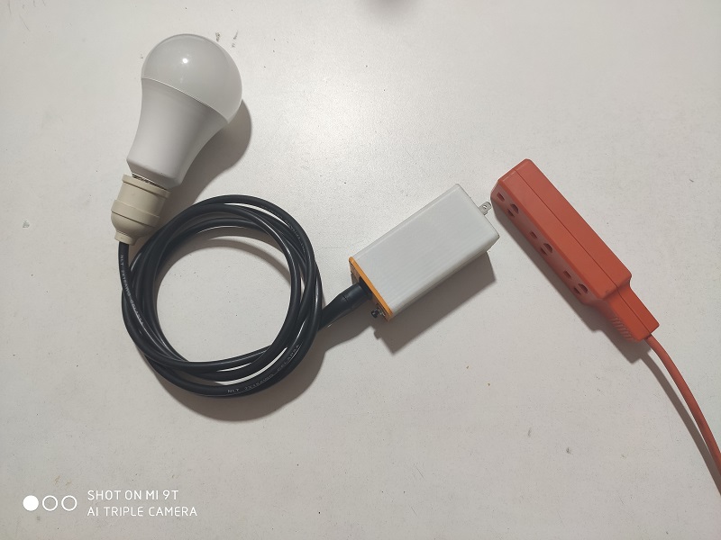
The electronic card and the adapter source are inside the box:
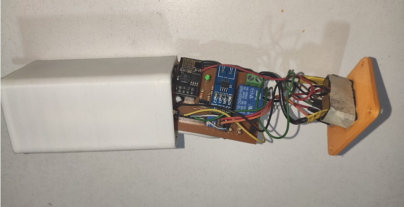
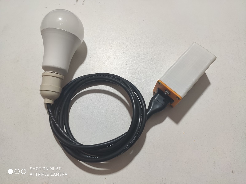
To demonstrate the on and off control of a contact using the MQTT protocol, a 220VAC load is required to control its on and off.
This is a 220VAC connector and a bulb insert socket.
Software of Controlling
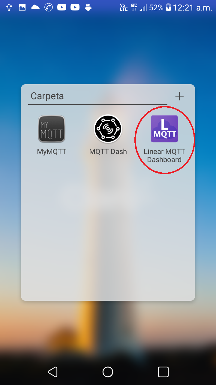
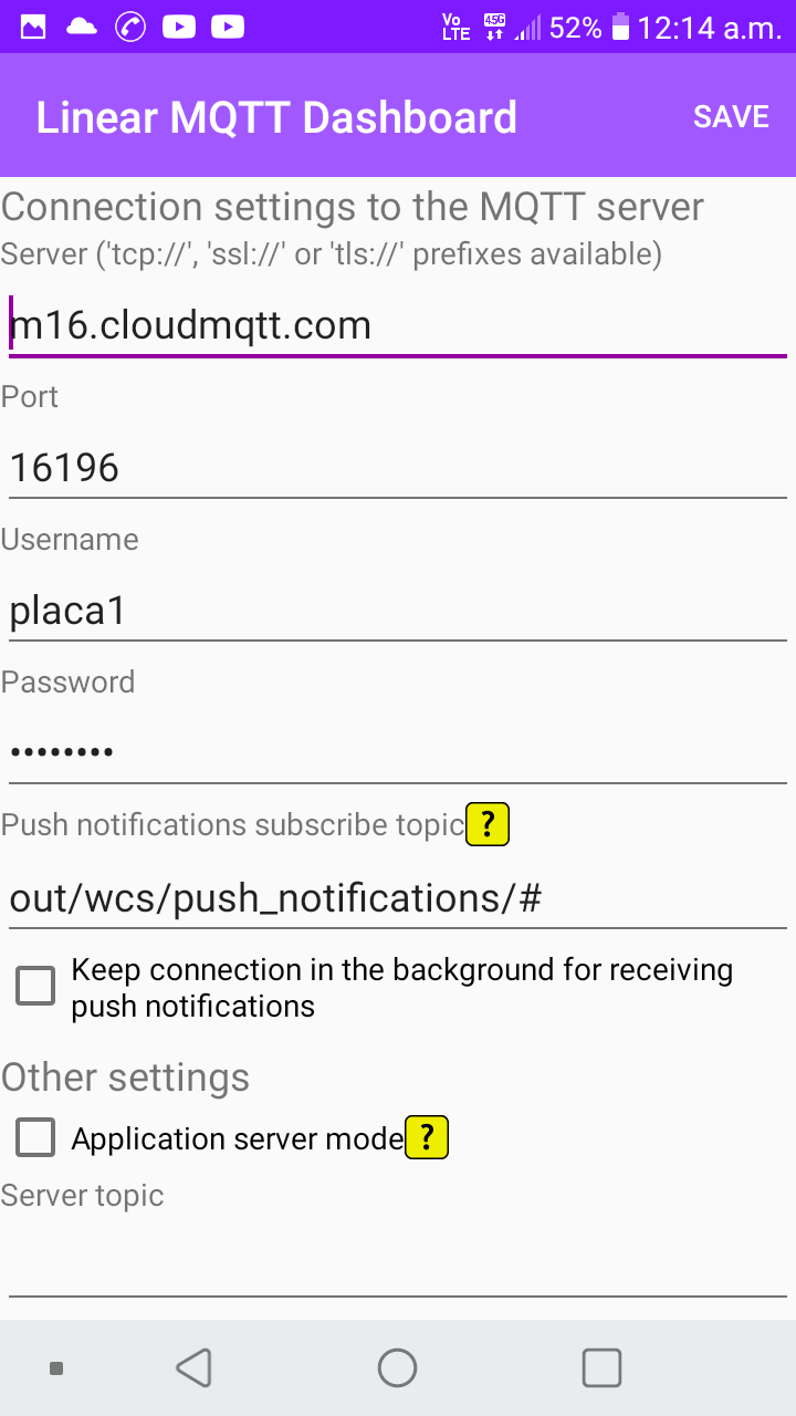
For the control through an Android program we will use an APP named Linear MQTT located in the APP Store, after installed, we open it
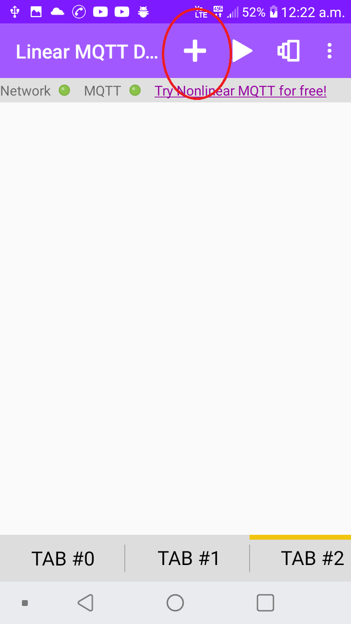
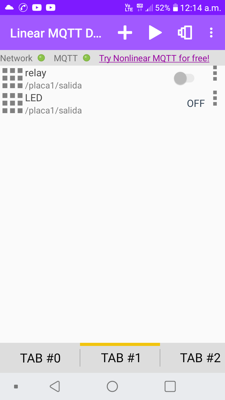
I place myself in an empty TABx, to add new objects, and press the _ + _ button:
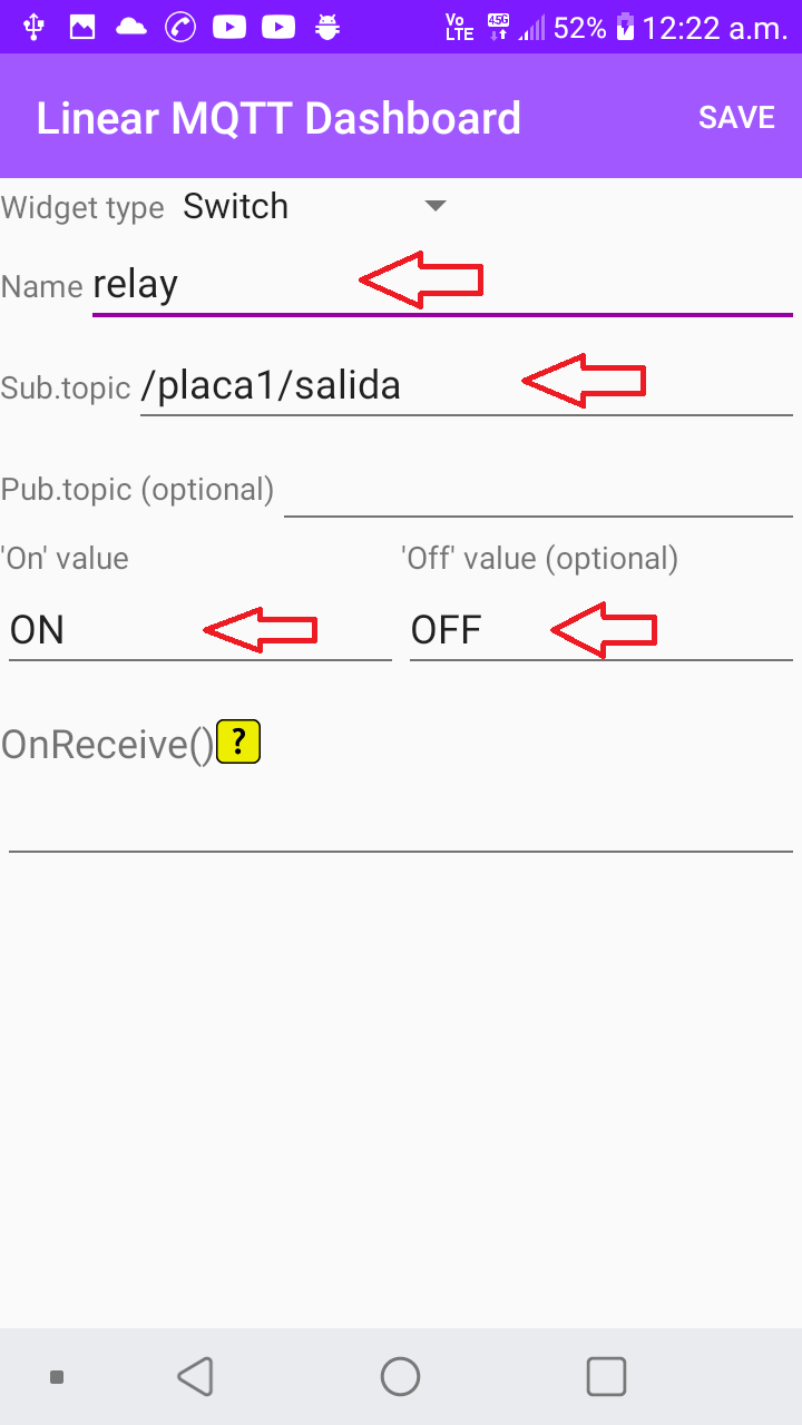
Add an object of type switch in it that will have the data of the variable _ /placa1/salida_
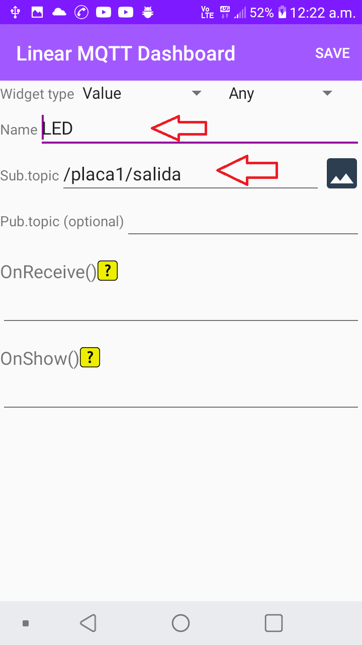
In the same way, add an LED that would be linked to the same variable, with the intention of seeing the data written from any device.
Here we have the objects that we require to control a contact.
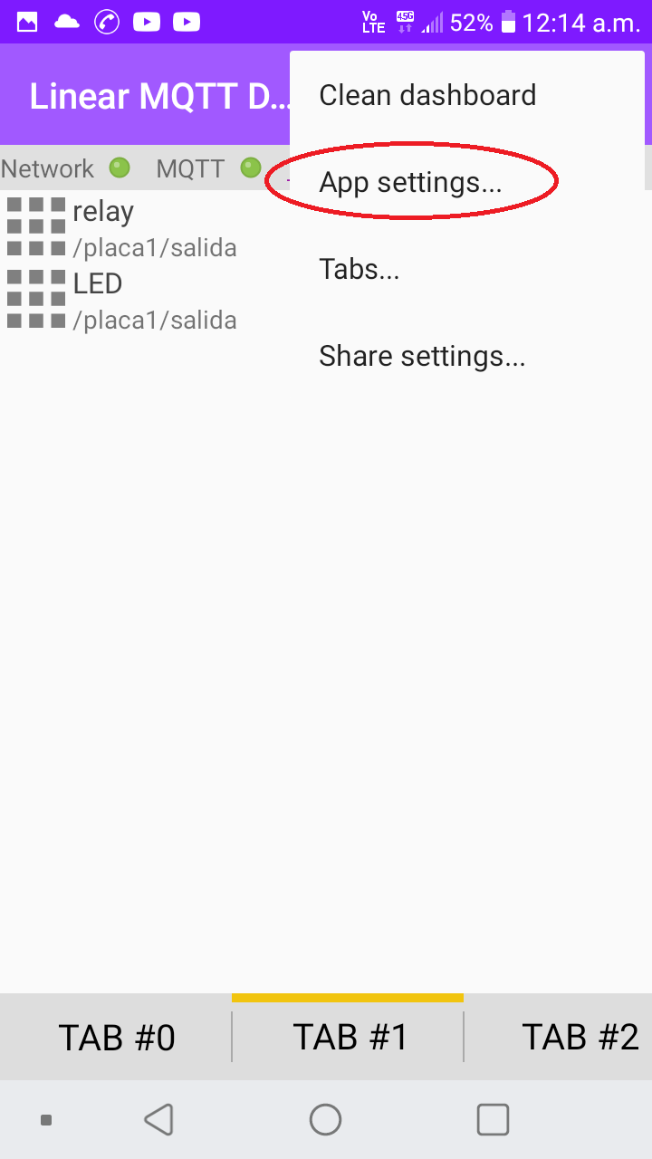
To Add the user data, you access the App settings:
We enter the broker and user data:
Operating
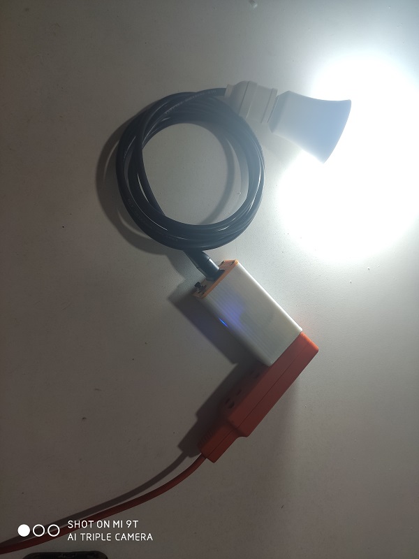
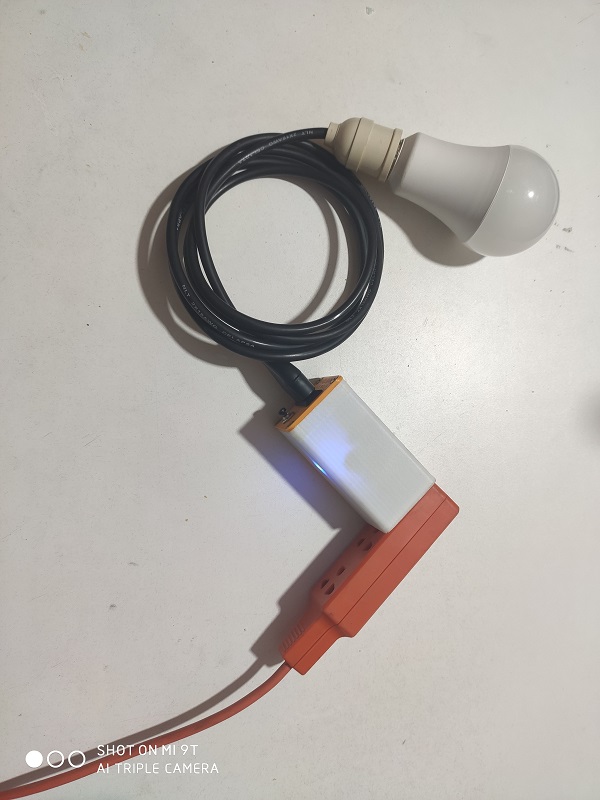
For the contact control operation, the project is placed with a load that is a 220VAC lamp
If I send the command to turn on the contact, the light is turned on for
If I send the command to turn off the contact, the lamp will turn off.
For the demonstration of the operation of the project, the following video is available:
GRUOP ASSIGNMENT:
In this group task I worked on a second printed circuit board to remotely control the light bulb, that is to say in another Wi-Fi to turn on the light bulb, I used an ESP8266 card in your ESP-01 model and the MQTT communication protocol.
Electronic
For the remote control of the bulb, only 1 digital input is required through a button, but we have added some additional digital inputs.
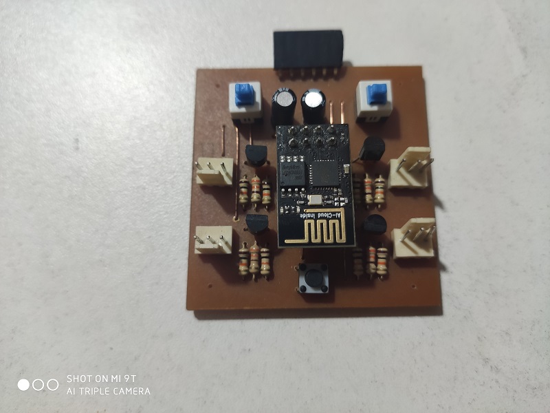
The PCB design was done with through-hole mounting component:
This is the card assembled with the ESP-01 card for programming and communication
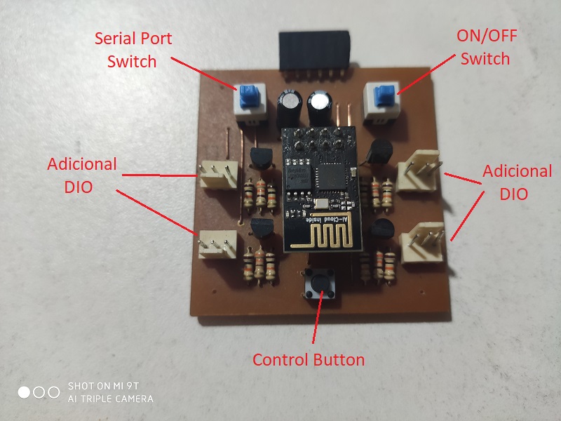
These are the parts designed on the electronic board
This is the electronic board ready to be programmed and used
Programming the Board
The ESP-01 program is the same as the first card, since they access the same variable in the CloudMQTT Broker server, the difference is that the wireless network is different and the IP addresses are different.
This would be the program:
#include <ESP8266WiFi.h>
#include <PubSubClient.h>

//-------------------VARIABLES GLOBALES--------------------------
int contconexion = 0;

const char *ssid = "LA CASA DEL MUSICO";
const char *password = "chichorevilla2018";
char   SERVER[50]   = "m16.cloudmqtt.com";
int    SERVERPORT   = 16196;        // Es el solo PORT de la cuenta
String USERNAME = "placa1";         //"zksmmgxo";
char   PASSWORD[50] = "12345678";   //"W7WBuDzsd01D";

unsigned long previousMillis = 0;

char charPulsador [15];
String strPulsador;
String strTexto;
String strPulsadorUltimo;

char PLACA[50];

char valueStr[15];
String strtemp = "";
char TEMPERATURA[50];
char PULSADOR[50];
char SALIDADIGITAL[50];
char SALIDAANALOGICA[50];

bool pulsador_ant;
bool estado_led;

#define pin_relay 3
#define pin_boton 0

//--------------------------------------------------------------
WiFiClient espClient;
PubSubClient client(espClient);

//------------------------CALLBACK------------------------------
void callback(char* topic, byte* payload, unsigned int length) {

  char PAYLOAD[5] = "    ";
  for (int i = 0; i < length; i++) {
    PAYLOAD[i] = (char)payload[i];
  }
  if (String(topic) ==  String(SALIDADIGITAL)) {
    if (payload[1] == 'N'){
      digitalWrite(pin_relay, HIGH);
      estado_led = HIGH;
      strTexto = "Consumiendo";
      strTexto.toCharArray(valueStr, 15);
      client.publish(SALIDAANALOGICA, valueStr);
    }
    if (payload[1] == 'F'){
      digitalWrite(pin_relay, LOW);
      estado_led = LOW;
      strTexto = "No Consume ";
      strTexto.toCharArray(valueStr, 15);
      client.publish(SALIDAANALOGICA, valueStr);
    }
  }
}

//------------------------RECONNECT-----------------------------
void reconnect() {
  uint8_t retries = 3;
  // Loop hasta que estamos conectados
  while (!client.connected()) {
    // Crea un ID de cliente al azar
    String clientId = "ESP8266Client-";
    clientId += String(random(0xffff), HEX);
    // Attempt to connect
    USERNAME.toCharArray(PLACA, 50);
    if (client.connect("", PLACA, PASSWORD)) {
      client.subscribe(SALIDADIGITAL);
      client.subscribe(SALIDAANALOGICA);
    } else {
      // espera 5 segundos antes de reintentar
      delay(5000);
    }
    retries--;
    if (retries == 0) {
      // esperar a que el WDT lo reinicie
      while (1);
    }
  }
}

//------------------------SETUP-----------------------------
void setup() {
  pinMode(13, OUTPUT); // D7 salida analógica
  analogWrite(13, 0); // analogWrite(pin, value);
  pinMode(pin_relay, FUNCTION_3);
  pinMode(pin_relay, OUTPUT); // D6 salida digital
  digitalWrite(pin_relay, LOW);

  // Entradas
  pinMode(14, INPUT); // D5
  pinMode(pin_boton, INPUT); // D0

  // Conexión WIFI
  WiFi.begin(ssid, password);
  while (WiFi.status() != WL_CONNECTED and contconexion <50) { //Cuenta hasta 50 si no se puede conectar lo cancela
    ++contconexion;
    delay(500);
  }
  if (contconexion <50) {
      IPAddress ip(192,168,1,198);
      IPAddress gateway(192,168,1,1);
      IPAddress subnet(255,255,255,0);
      WiFi.config(ip, gateway, subnet);
  }
  else {
  }

  client.setServer(SERVER, SERVERPORT);
  client.setCallback(callback);

  String temperatura = "/" + USERNAME + "/" + "temperatura";
  temperatura.toCharArray(TEMPERATURA, 50);
  String pulsador = "/" + USERNAME + "/" + "pulsador";
  pulsador.toCharArray(PULSADOR, 50);
  String salidaDigital = "/" + USERNAME + "/" + "salida";
  salidaDigital.toCharArray(SALIDADIGITAL, 50);
  String salidaAnalogica = "/" + USERNAME + "/" + "salidaAnalogica";
  salidaAnalogica.toCharArray(SALIDAANALOGICA, 50);
}

//--------------------------LOOP--------------------------------
void loop() {

  if (!client.connected()) {
    reconnect();
  }
  client.loop();

  unsigned long currentMillis = millis();

  if (currentMillis - previousMillis >= 10000) { //envia la temperatura cada 10 segundos
    previousMillis = currentMillis;
    int analog = analogRead(17);
    float temp = analog*0.322265625;
    strtemp = String(temp, 1); //1 decimal
    strtemp.toCharArray(valueStr, 15);
    client.publish(TEMPERATURA, valueStr);
  }
  if (pulsador_ant!=digitalRead(pin_boton)){
    pulsador_ant = digitalRead(pin_boton);
    if(digitalRead(pin_boton)==LOW){
      delay(200);
      if(digitalRead(pin_boton)==LOW){
        if (estado_led){
          strPulsador = "OFF";
          estado_led = LOW;
        } else {
          strPulsador = "ON";
          estado_led = HIGH;
        }
      }
    }
  }

  if (strPulsador != strPulsadorUltimo) { //envia el estado del pulsador solamente cuando cambia.
    strPulsadorUltimo = strPulsador;
    strPulsador.toCharArray(valueStr, 15);
    client.publish(SALIDADIGITAL, valueStr);
  }
}
Testing the Comunications with Two Boards
Now we are ready to test it.
Designed Files
| Description | Files |
|---|---|
| Program Project Board | Termanal_1.ino |
| Schematic | Ioter.sch |
| Board | Ioter.brd |
| Program Second Board | Termanal_2.ino |
| Schematic 2 | IOT-ESP-01.sch |
| Board 2 | IOT-ESP-01.brd |
| Box | Caja.ipt |
| Top | Tapa.ipt |