17. Wildcard Week
Assignment
- Design and produce something with a digital fabrication process (incorporating computer-aided design and manufacturing) not covered in another assignment, documenting the requirements that your assignment meets, and including everything necessary to reproduce it
This week I will make a biped robot inspired by a robot widely used in Education, it is Otto Robot
I will call Betto, to achieve this robot requires:
I have done it:
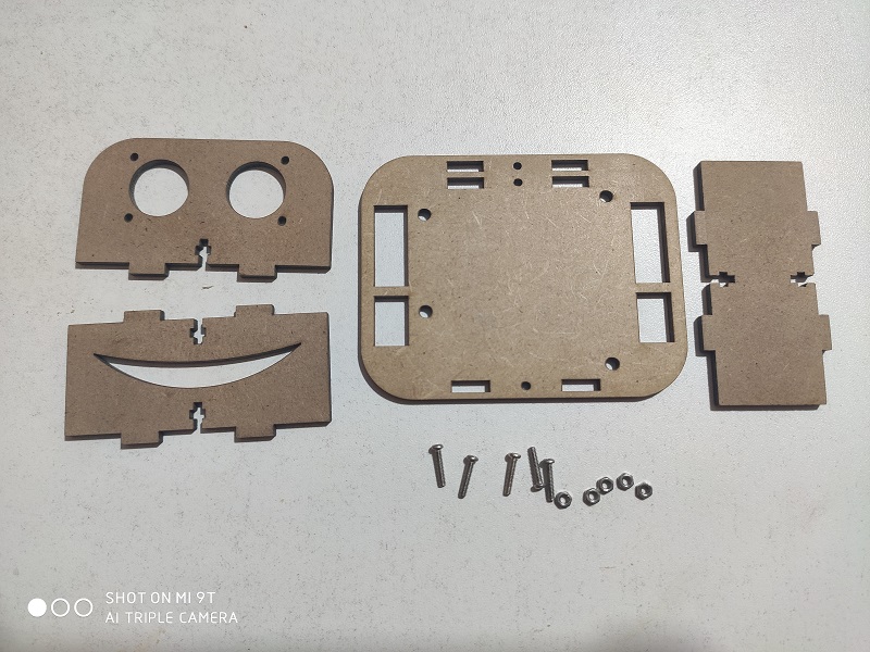
- 3D design: It is for lasercut in MDF of 3mm
- Robot Firmware: It is in Arduino IDE
- App for Android: It is developped in APP Inventor 2 from MIT
I have used from the commercial:
- Electronic board, Arduino Nano and Shield
Let’s start
Inspiration
Otto is a robot widely used in Education to teach programming, electronics and robotics, it can even be used to test mathematics, reasoning among others.
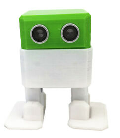
We will work on a similar model with our own parts:
3D Design
For the 3D design I have used the Autodesk Inventor Software, to design flat parts for laser cutting.
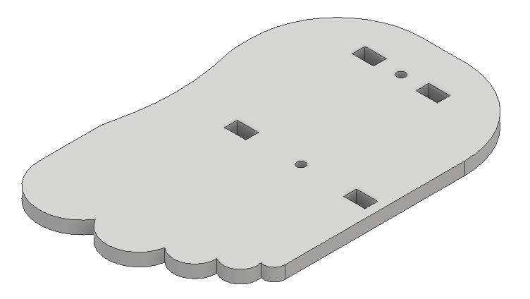
First we will start with the soles of the feet:
Here we have the finished sole of the feet:
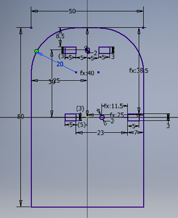
For the head and eyes we made a model with these characteristics:
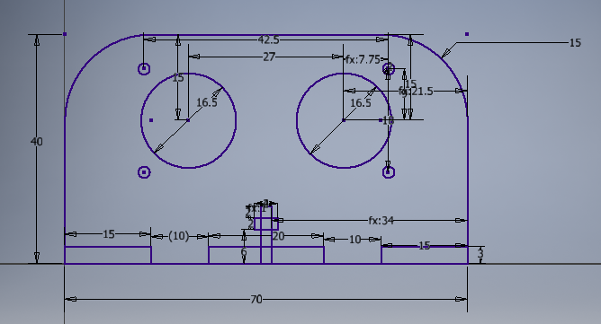
Here we have the design of the head:
The front and rear head supports

Here we have the finished design:
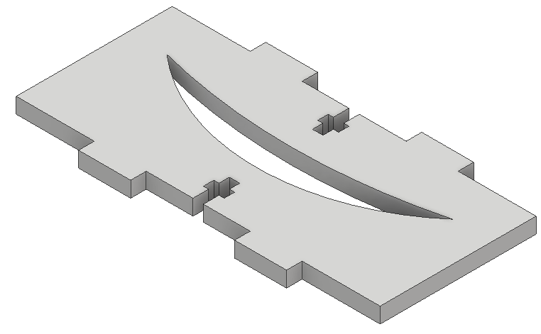
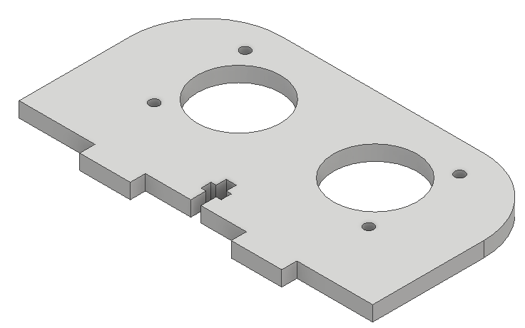
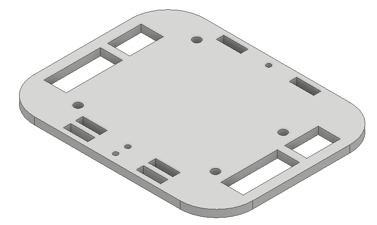
Designing the Servo Motor Platform
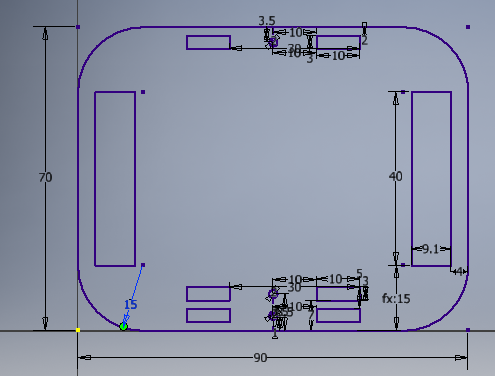
Here the finished platform
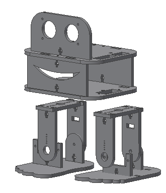
We can see a sample of our robot Assembled in the software
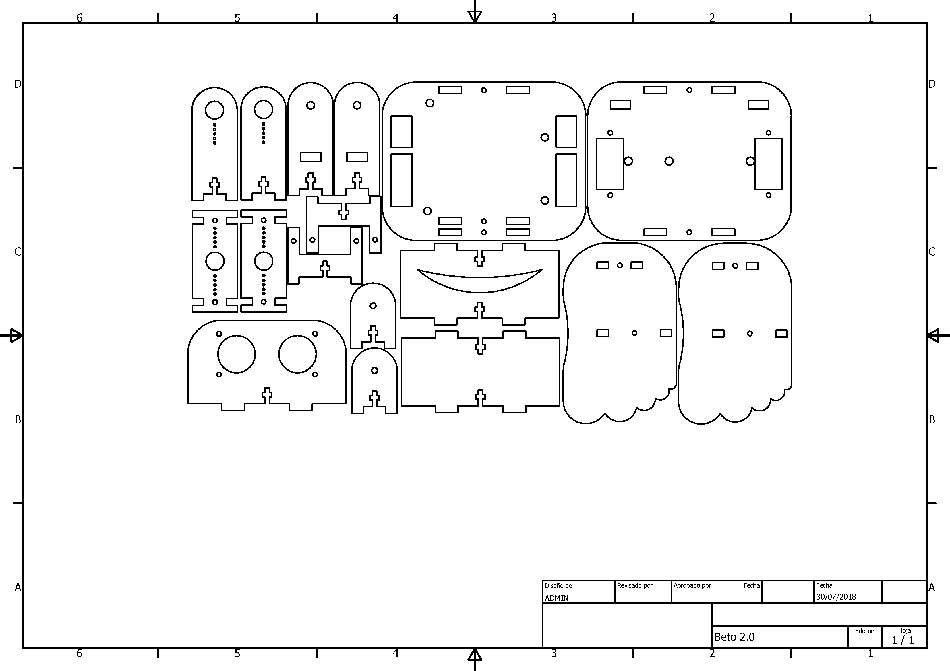
We export the designs in dwg file for laser cutting, in this case 3mm MDF was used and proceeded as in week 4: Computer Controlled Cuting
Electronics Parts
To control the movement of the bidepo, we have the following diagram:
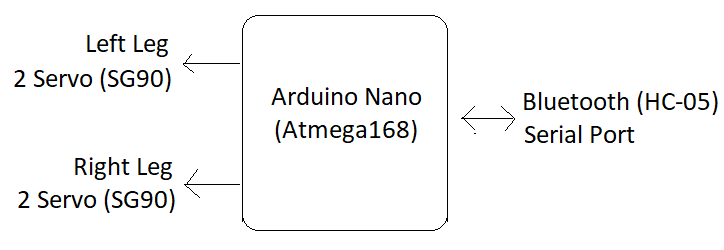
The components are:
- 1und Arduino Nano
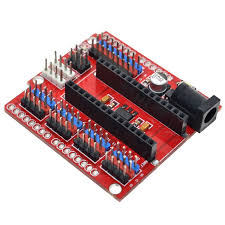
- 1und Shield to Arduino Nano
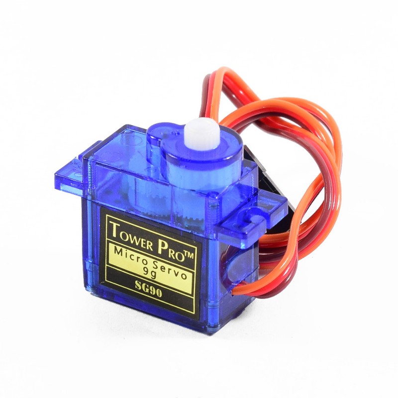
- 4unds SG90 Servomotors
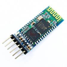
- 1 unit of Bluetooth Module HC-05
- Cables and connectors
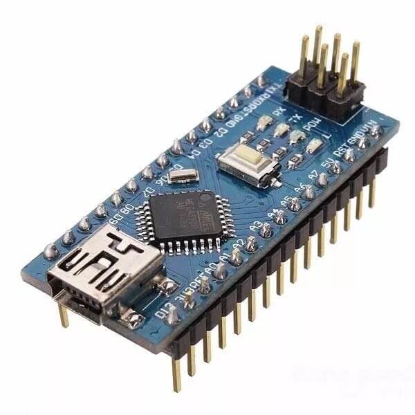
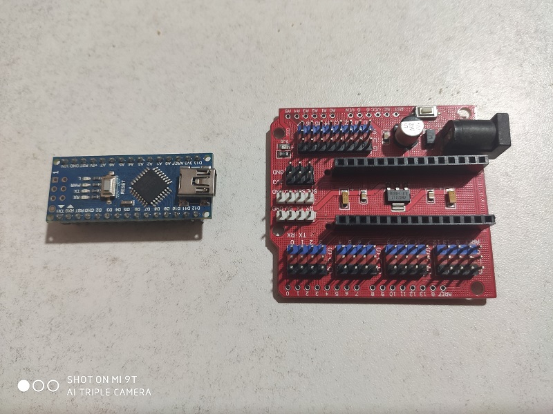
This is the Arduino Nano
This is the shield for Arduino nano, its function is to extend the connectivity of the Arduino’s output pins.
Servo motors of 0.5Kg of pork on the rotary axis.
The HC-05 Bluetooth communication module
Assembling Robot
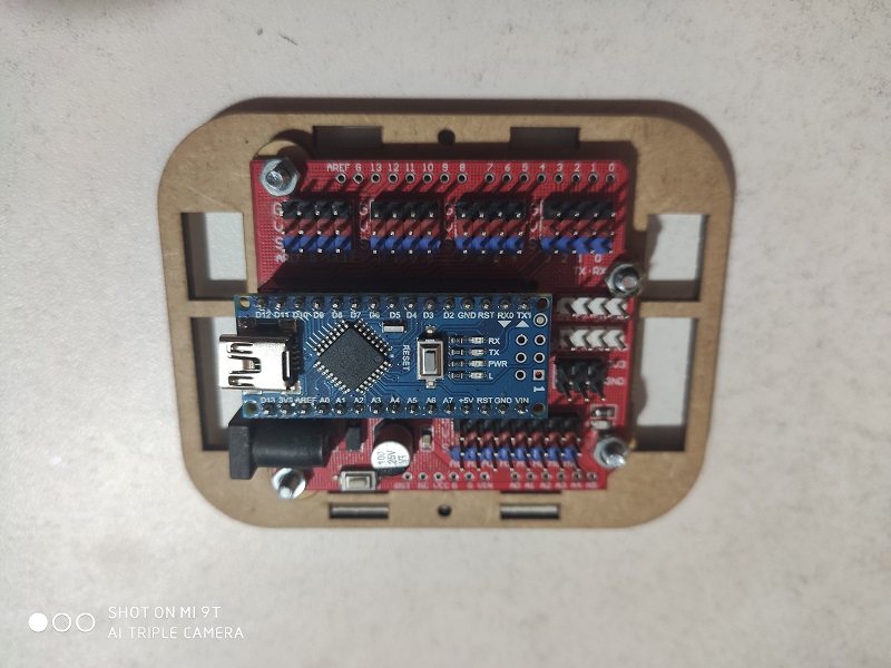
After cutting the design and having the electronic parts recognized, we started the assembly:
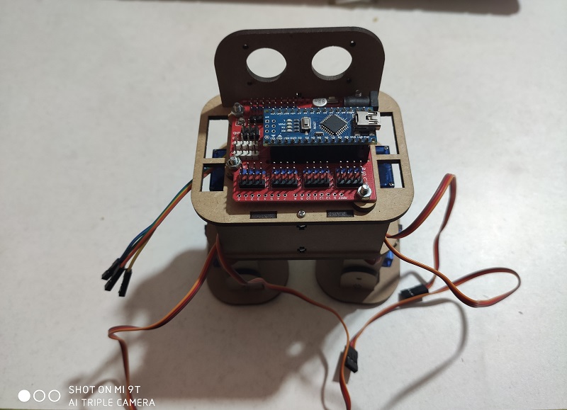
We prepare the electronics of the Arduino Nano and Shield.
We assemble the parts as indicated in the figure:
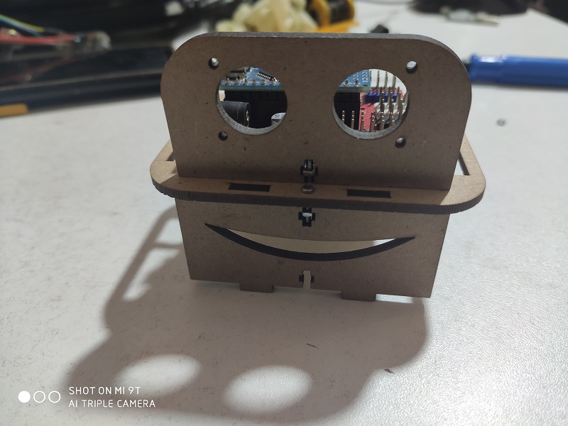
We place the head so that said part is already assembled:
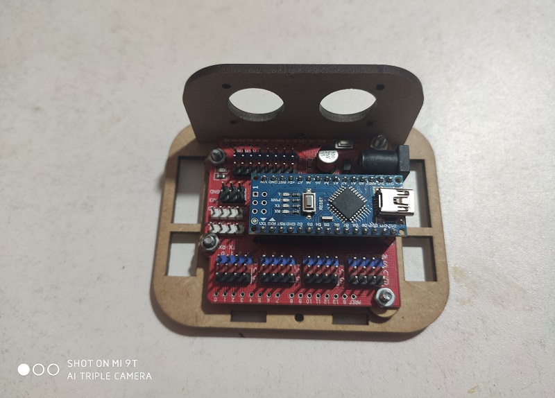
We place the head supports at the bottom:
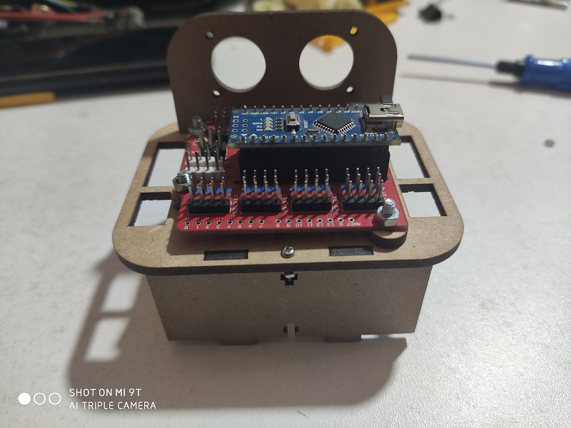
This is the front view:
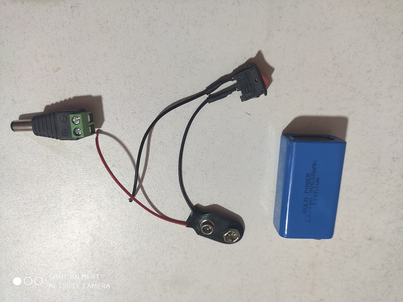
We prepare the battery and the connectors to turn the robot on and off.
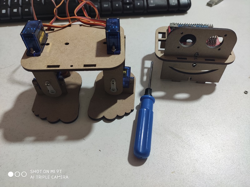
We assemble the lower part with the SG-90 servomotors:
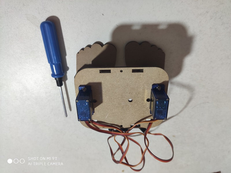
For the assembly we take into account the position of the servomotors, these must be centered at 90 ° to achieve their maximum movement.
We install the battery and the Bluetooth module and secure.
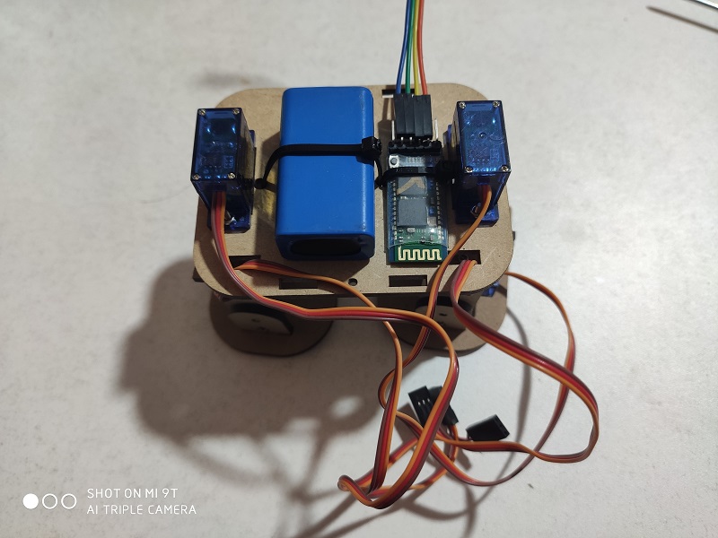
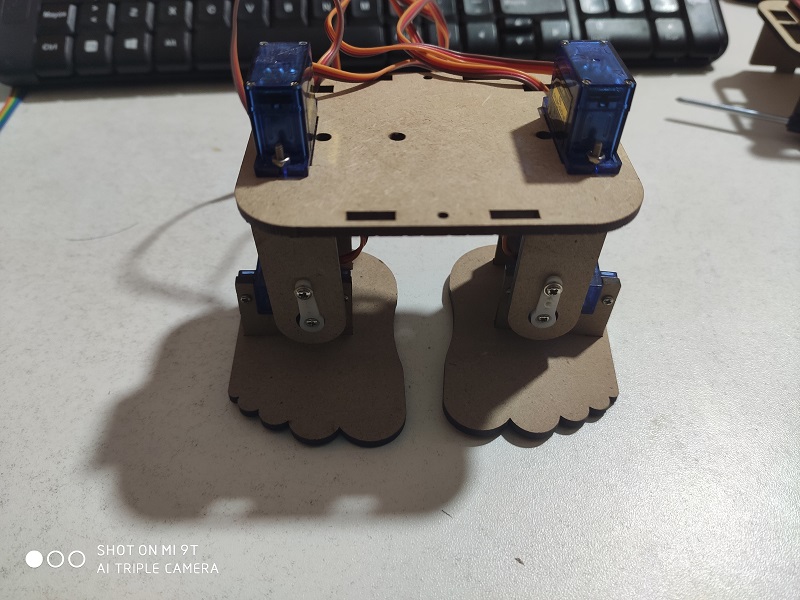
Here we have the previously assembled parts:
We assemble the robot and review the details of the position of the cables:
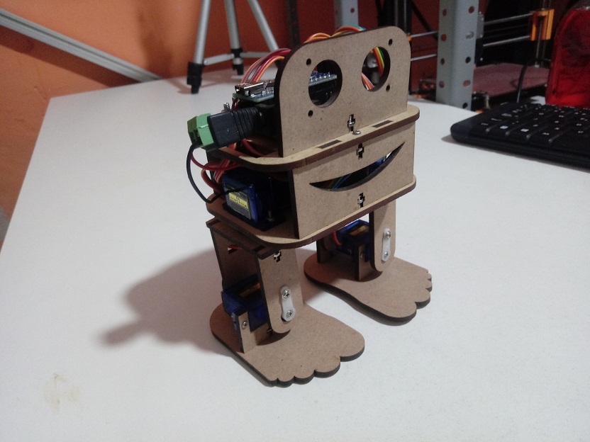
Here we have the Beto robot finished and ready to be programmed with the firmware.
Program Firmware Robot
The software has been developed in the Arduino Ide software, having as control commands the following commands through the serial port:
| Item | Data | Command |
|---|---|---|
| 1 | 0 | Stop |
| 2 | 1-254 | Relative Velocity |
| 3 | 255 | Start |
The most useful routine in the robot is the half-step sequence control.
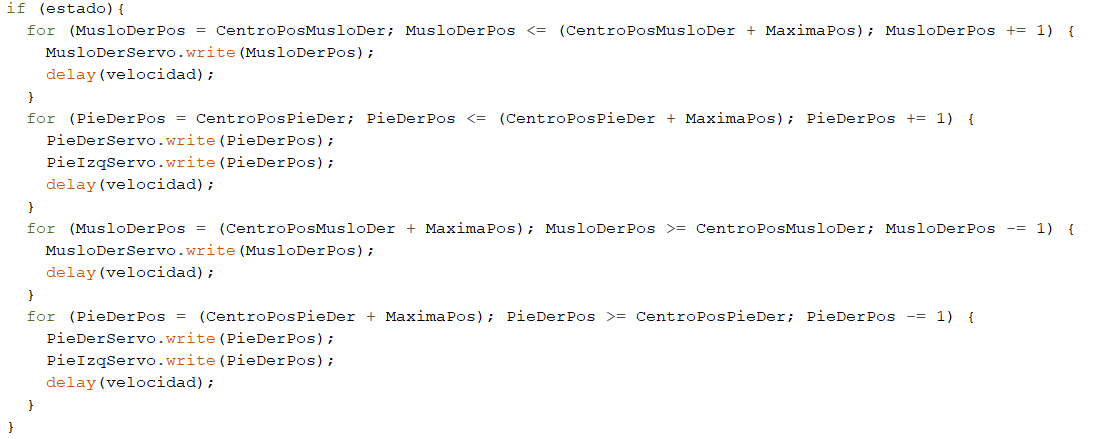
The complete program is the following:
/ Define the Servo Class
#include <Servo.h>
Servo PieDerServo,MusloDerServo;
Servo PieIzqServo,MusloIzqServo;

// References Positions
#define CentroPosPieDer   90
#define CentroPosPieIzq   90
#define CentroPosMusloDer 90
#define CentroPosMusloIzq 90
#define MaximaPos         30
#define MinimaPos         -30

// Variables to control
int velocidad=20;
byte PieDerPos=CentroPosPieDer,MusloDerPos=CentroPosMusloDer;
byte PieIzqPos=CentroPosPieIzq,MusloIzqPos=CentroPosMusloIzq;
byte dato_serie;
bool estado = LOW;

// Setup Function to set the config and the initial values
void setup() {
  // Begin the Servos
  PieDerServo.attach(5);
  PieIzqServo.attach(4);
  MusloDerServo.attach(3);
  MusloIzqServo.attach(2);
  PieDerServo.write(PieDerPos);
  MusloDerServo.write(MusloDerPos);
  PieIzqServo.write(PieIzqPos);
  MusloIzqServo.write(MusloIzqPos);
  // Begin the Bluetooth
  Serial.begin(115200);
}
void loop() {
  // Secuence to move the right side
  if (estado){
    for (MusloDerPos = CentroPosMusloDer; MusloDerPos <= (CentroPosMusloDer + MaximaPos); MusloDerPos += 1) {
      MusloDerServo.write(MusloDerPos);
      delay(velocidad);
    }
    for (PieDerPos = CentroPosPieDer; PieDerPos <= (CentroPosPieDer + MaximaPos); PieDerPos += 1) {
      PieDerServo.write(PieDerPos);
      PieIzqServo.write(PieDerPos);
      delay(velocidad);
    }
    for (MusloDerPos = (CentroPosMusloDer + MaximaPos); MusloDerPos >= CentroPosMusloDer; MusloDerPos -= 1) {
      MusloDerServo.write(MusloDerPos);
      delay(velocidad);
    }
    for (PieDerPos = (CentroPosPieDer + MaximaPos); PieDerPos >= CentroPosPieDer; PieDerPos -= 1) {
      PieDerServo.write(PieDerPos);
      PieIzqServo.write(PieDerPos);
      delay(velocidad);
    }
  }
  // Secuence to move the left side
  if (estado){
    for (MusloIzqPos = CentroPosMusloIzq; MusloIzqPos >= (CentroPosMusloIzq + MinimaPos); MusloIzqPos -= 1) {
      MusloIzqServo.write(MusloIzqPos);
      delay(velocidad);
    }
    for (PieIzqPos = CentroPosPieIzq; PieIzqPos >= (CentroPosPieIzq + MinimaPos); PieIzqPos -= 1) {
      PieDerServo.write(PieIzqPos);
      PieIzqServo.write(PieIzqPos);
      delay(velocidad);
    }
    for (MusloIzqPos = (CentroPosMusloIzq + MinimaPos); MusloIzqPos <= CentroPosMusloIzq; MusloIzqPos += 1) {
      MusloIzqServo.write(MusloIzqPos);
      delay(velocidad);
    }
    for (PieIzqPos = (CentroPosPieIzq + MinimaPos); PieIzqPos <= CentroPosPieIzq; PieIzqPos += 1) {
      PieDerServo.write(PieIzqPos);
      PieIzqServo.write(PieIzqPos);
      delay(velocidad);
    }
  }
}
void serialEvent(){
  // Serial event
  while (Serial.available()){
    dato_serie = Serial.read();
    switch(dato_serie){
      // Case the data is Turn ON
      case 255:
        estado = HIGH;
        Serial.println("ON");
      break;
      // Case the data is Turn OFF
      case 0:
        estado = LOW;
        Serial.println("OFF");
      break;
      // Case the data is Change Velocity
      default:
        velocidad = map(dato_serie,1,254,8,30);
        Serial.println(velocidad);
      break;
    }
  }
}
// End the Program
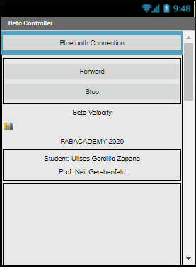
APP Design for Android
To make the program for Android, we have used the online software of App Inventor 2 from MIT

We can see the design interface of the App.
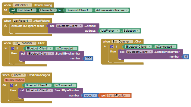
Here we have the block program.
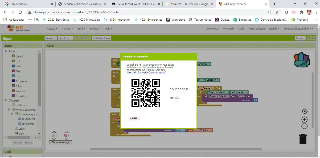
To perform the tests on the mobile, first we start the publication of the application in its AI Companion linker
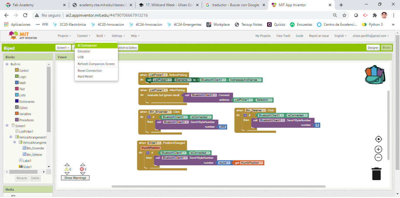
A QR code is created to synchronize with the AI Companion Software of the platform:
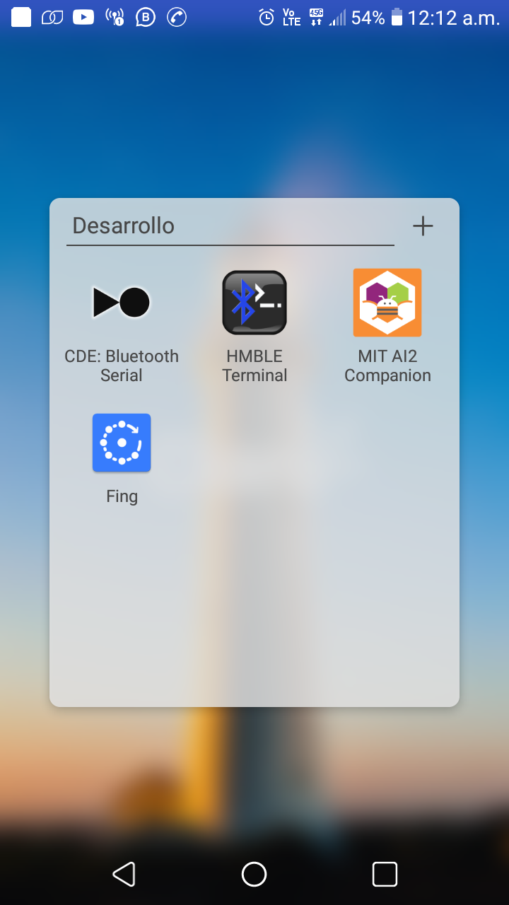
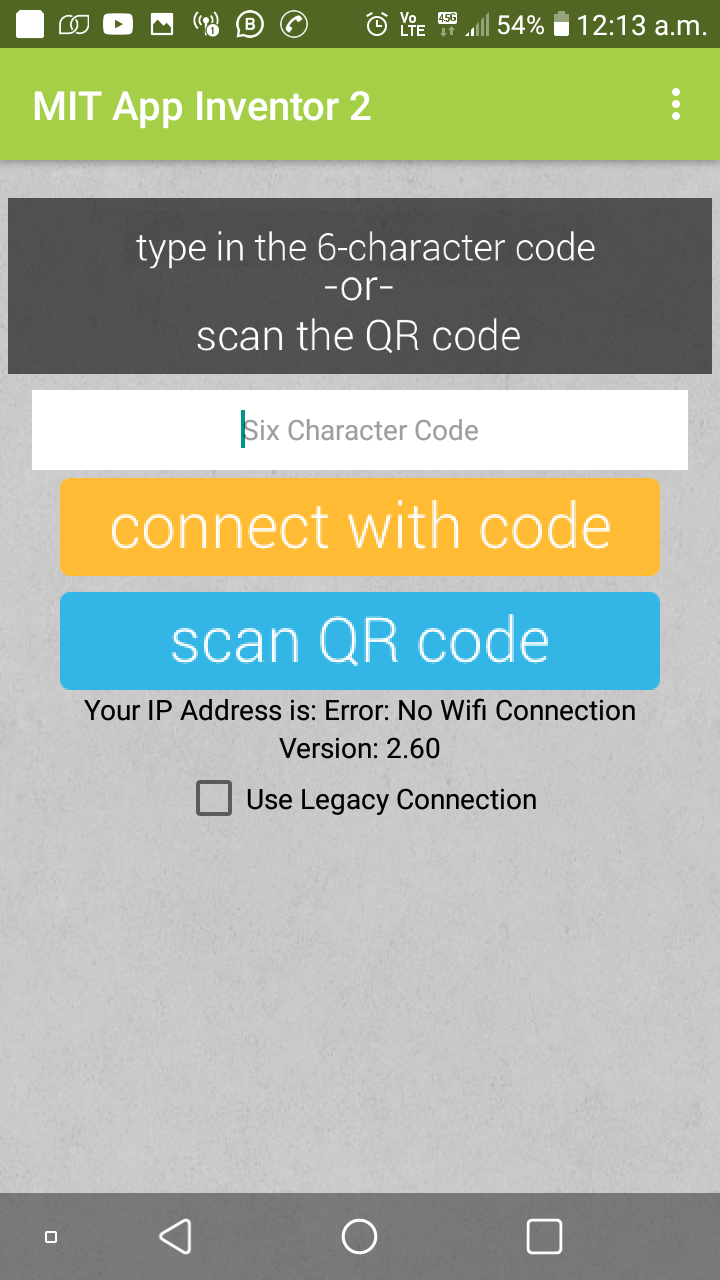
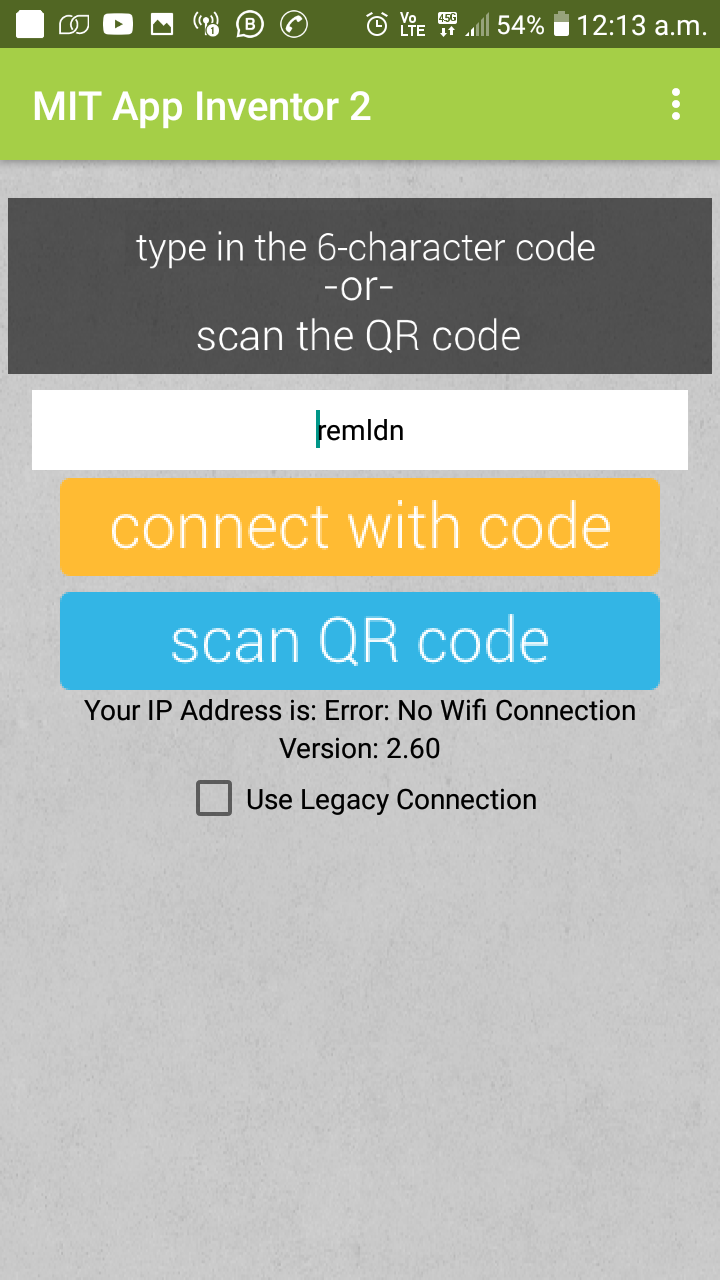
We open the application on Android:
We choose scan QR code to synchronize with the program:
We scan the bar code in App Inventor 2, keep in mind that this key and synchronization is temporary, it is only for testing, but if we want to install we must create the .apk file
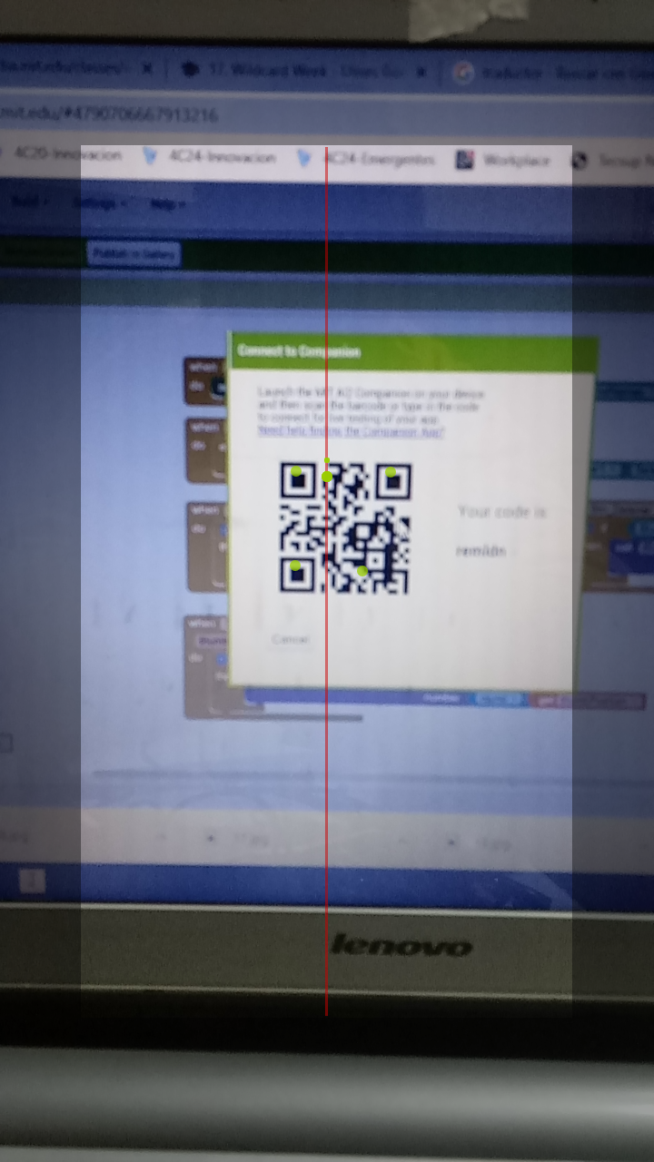
Here we can see that the code linked to the App Inventor 2 program was scanned
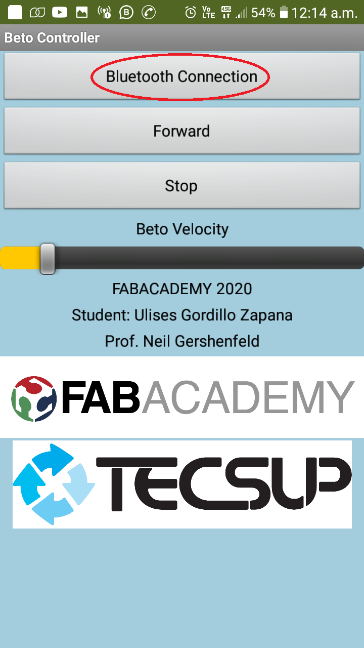
We turn on the robot, press the button to connect via Bluetooth with the Robot
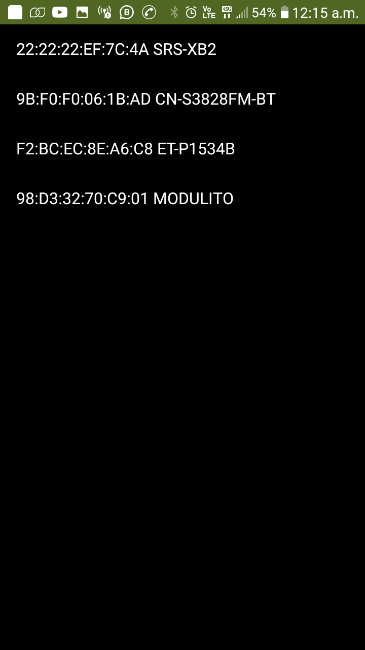
We choose the Modulito and thus we have named our HC-05 Bluetooth module:
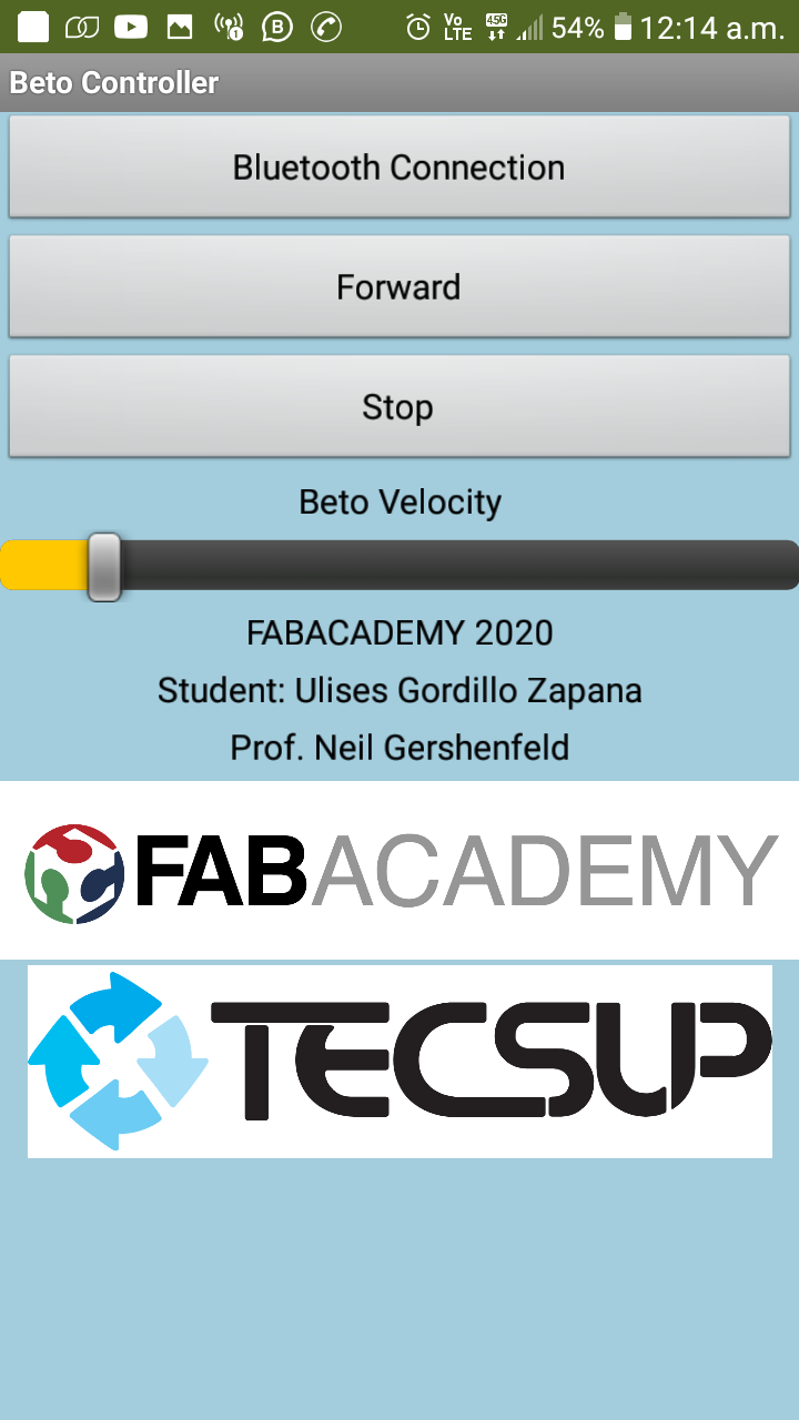
Finally we have the application ready to control it.
Demostration
Protecting Betto from Covid19
In this additional work we carry out the design, the manufacture of a mask to protect it from Covid19.
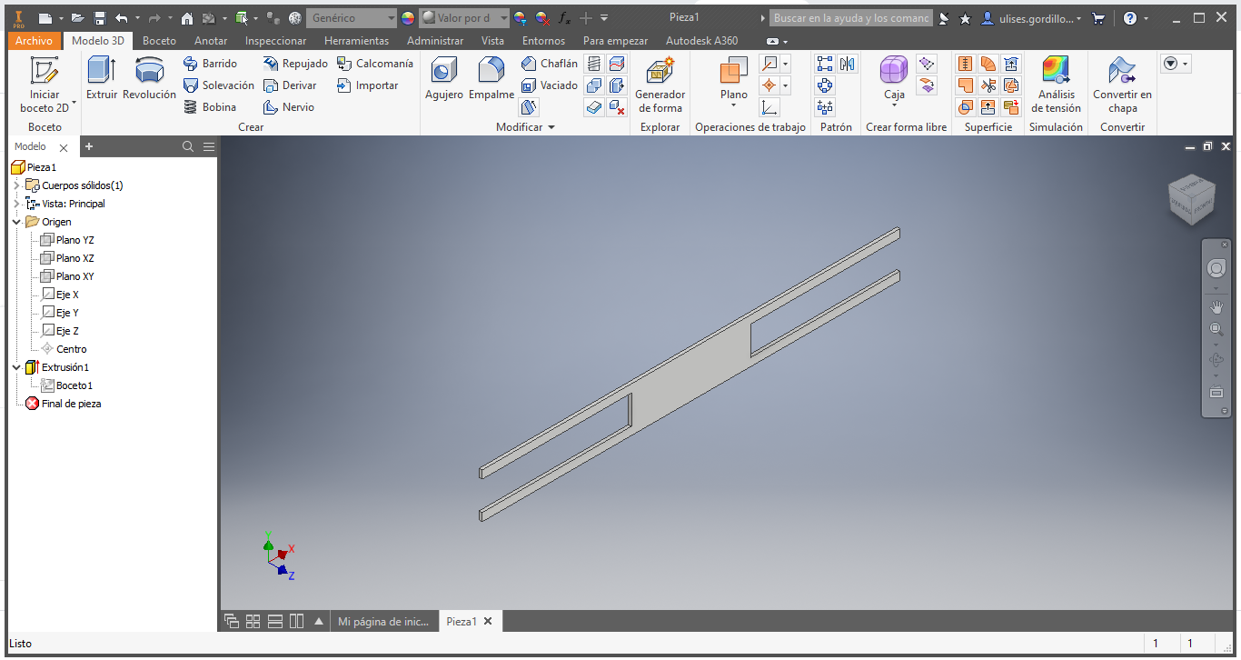
Here we have the design in Autodesk inventor
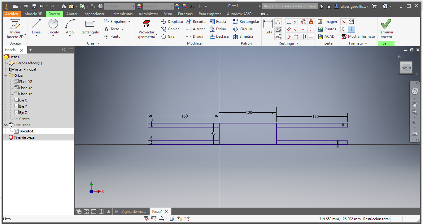
We have the 3D design:
We extract the 2D file for the Cut
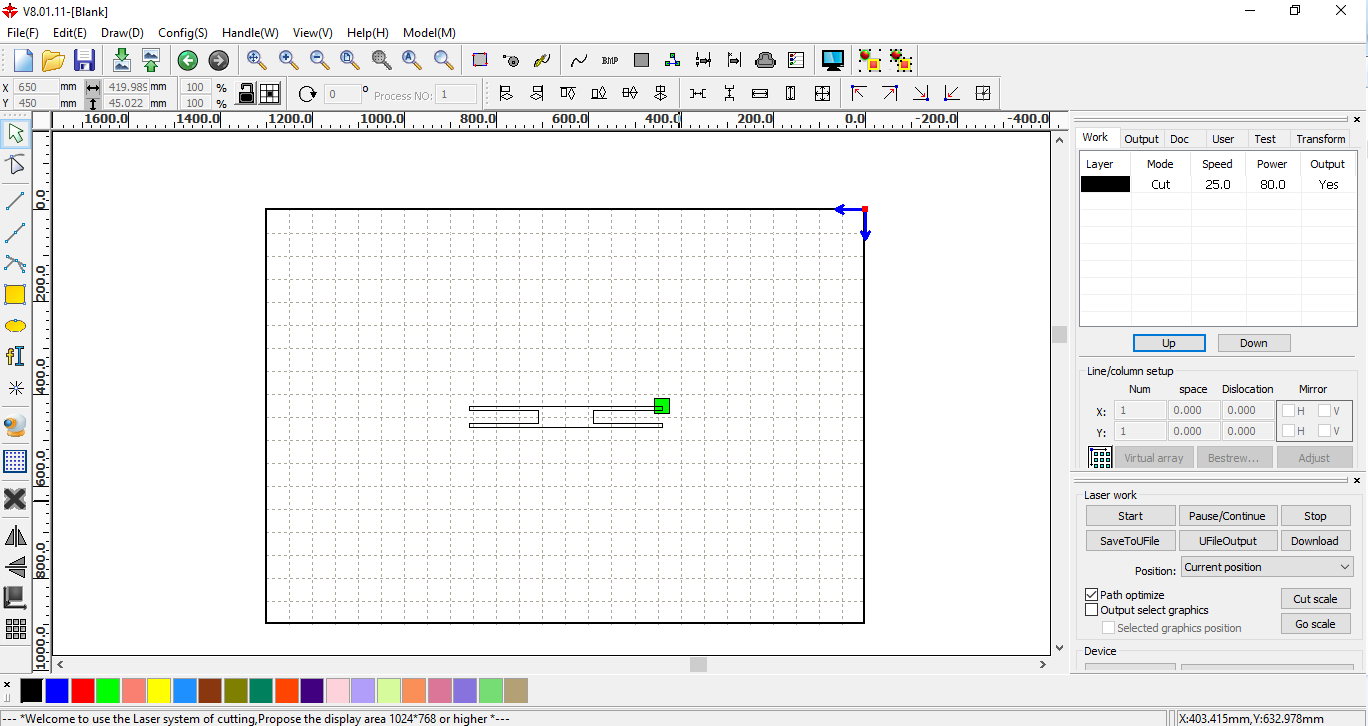
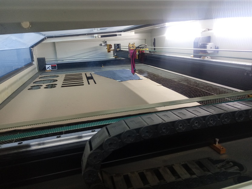
We load the file in the RDWorks Software to generate a cutting process:
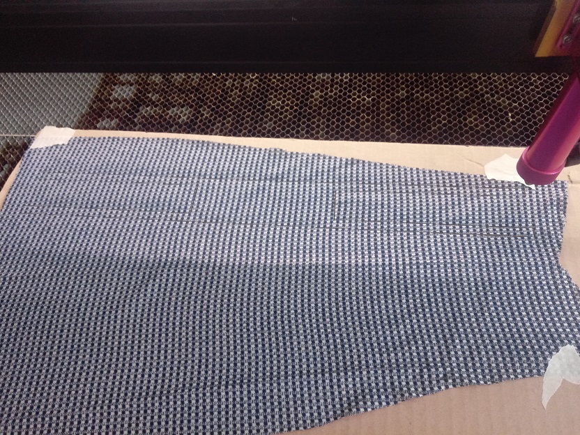
To achieve the cut in fabric, we must stretch the material very well, in this case, stretch it on a cardboard sheet and fasten it with adhesive tape.
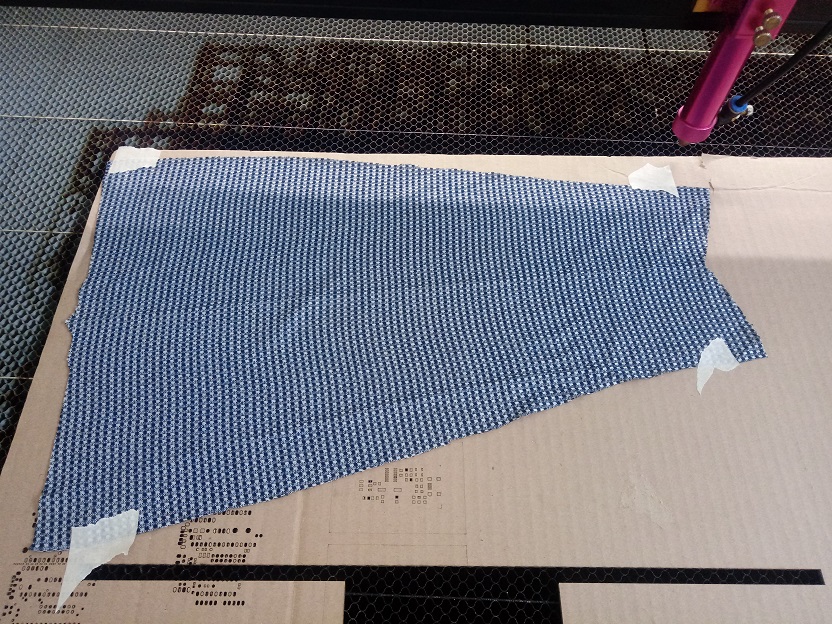
We can see by cutting the design, with the speed at 100mm / s and 30% CO2 laser power.:
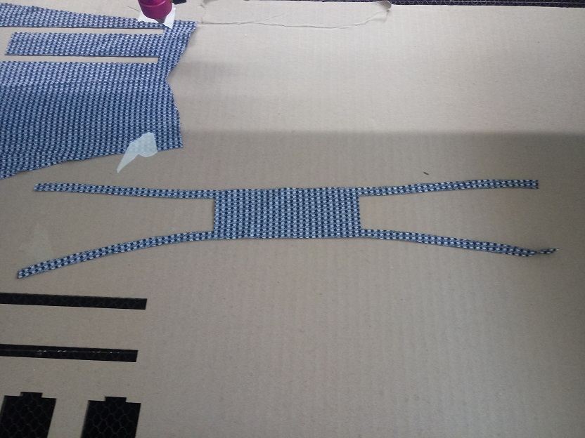
Now we can see that the cut is achieved.
We see the manufactured design. this cut went well:
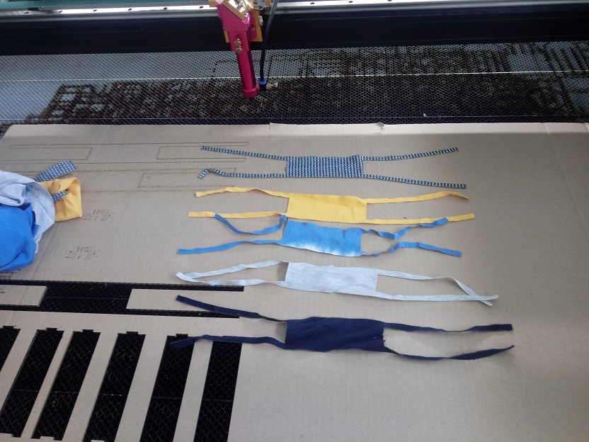
With the same characteristics we cut other colors and types of fabrics, the result was as expected, clean cuts without excesses or lack of cutting, a recommendation, the compressed air of the machine must be strong, since it helps to threaten the fire if it is generated when cutting.
Here we can see Betto with his protection mask against Covid19.
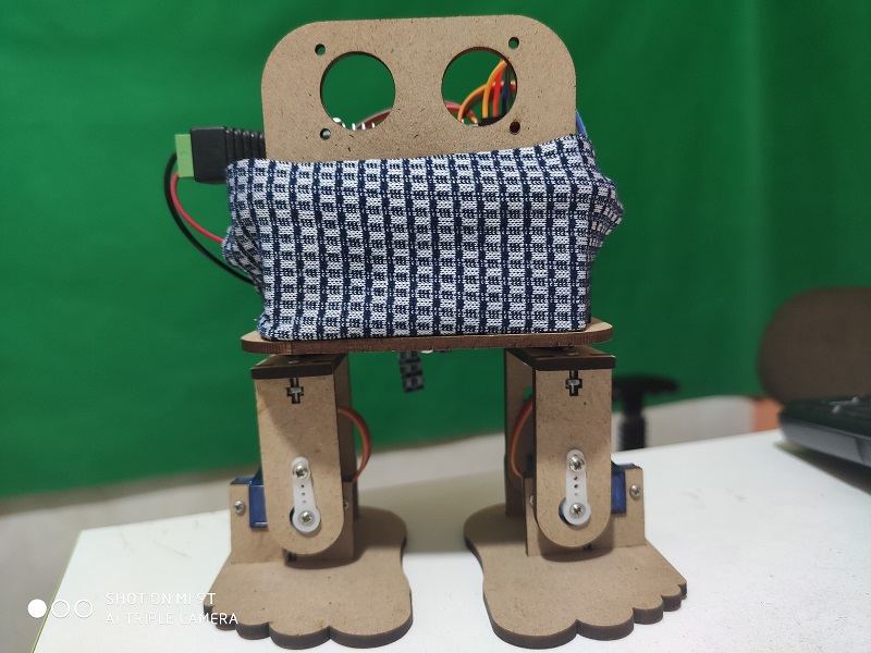
Now with another model of fabric and color:
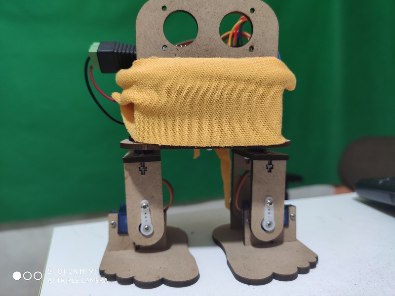
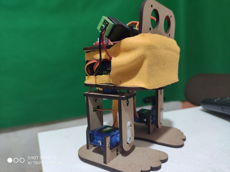
Now viewed from another profile, and showing the details.
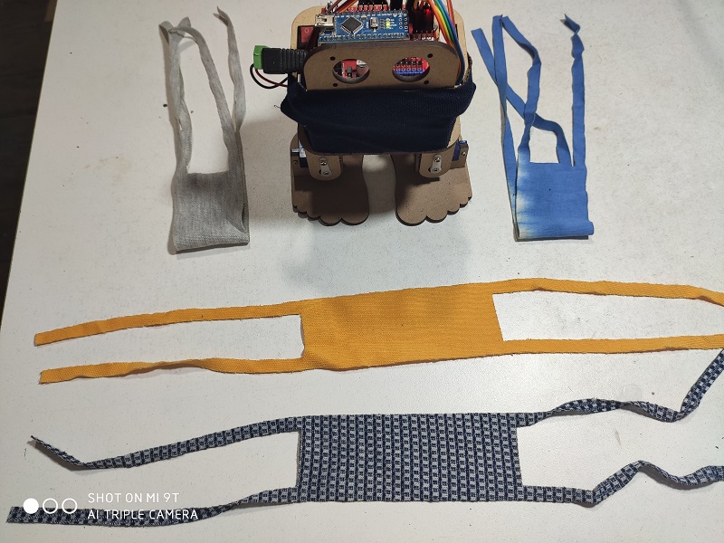
Finally, this would be your collection of protection masks against Covid19.
Designed Files
| Description | Files |
|---|---|
| Base Body | Base_Cuerpo.ipt |
| Arduino Platform | Base_Cuerpo_Arduino.ipt |
| All design | Beto2.0-Informe.dwg |
| Arduino Program | Beto_Program.ino |
| Foot | Planta.ipt |
| Body Vertical | Separador_Cuerpo.ipt |
| Body vertical 2 | Separador_Cuerpo_Plano.ipt |
| Head | Soporte_Ultrasonido.ipt |
| Servomotor Supoort | SoporteSG90.ipt |
| Servomotor Leg | SoporteSG90_Leg.ipt |
| Servomotor Leg 2 | SoporteSG90_LegAtras.ipt |
| Servomotor Led 3 | SoporteSG90Atras.ipt |
| Support Leg | Sujetador_Leg.ipt |
| Betto Protector | Mascarilla.ipt |