20. Project development
- Complete your final project tracking your progress.
Learning outcomes
- Implement project plan
- Apply time management techniques
- Summarise and communicate the essence of your project development
Have you answered these questions?
- what tasks have been completed, and what tasks remain?
- what has worked? what hasn’t?
- what questions need to be resolved?
- what will happen when?
- what have you learned?
Project Summary
My project consists in the development of a DIY RC car, that could be fabricated in any fablab. It represents my experimentations and learnins during fabacademy, along with my curiosity to build it as i wanted and see if i could go through and have as many of the ideas/features in done.
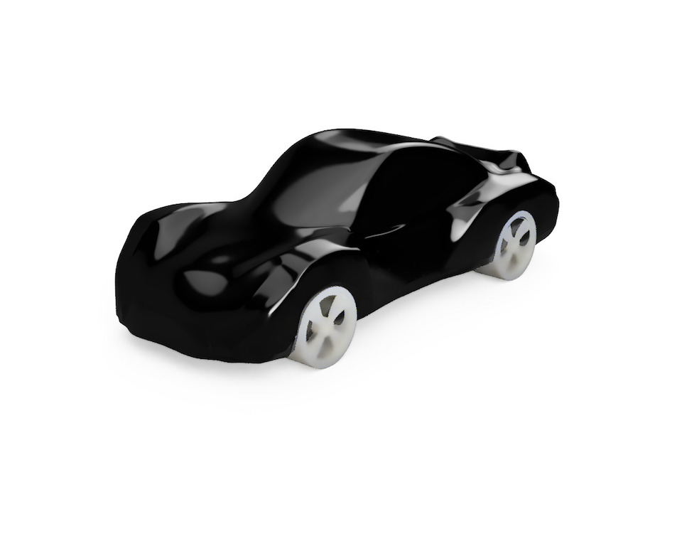
A 1/7 scale RC car that could be “easily” build (or adapted, improved) inside any FabLab.
So in summary, a DIY RC car platform that could be extended to later allow autonomous driving. To learn making, programming software, physics, having fun just driving around or with AI having fun doing autonomous racing on a budget (or maybe to explore some building, deliver goods, anyone could adapt or create own version).
Questions?
What tasks have been completed, and what tasks remain?
The the tasks that are mostly completed are the design and cut chassi, design and 3d print suspension elements and wheels. Assemble components with chassi. Design and fabricate the shell in carbon fiber. Design, stuffing and programming of the electronics: power pcb, controller pcb, sensors pcb with ESC to controll servo and motors. Connect pcbs with battery to connect to wifi network and operate the servo and brushless motor by using mobile app virtual joystick. The tasks that still remain, are related with front suspension, it’s not in a final project iteration that can be used. So car at the moment doesn’t turn left/right only forward. The ToF sensors aren’t in in use at the moment, need to be assembled in the car shell.
What has worked?
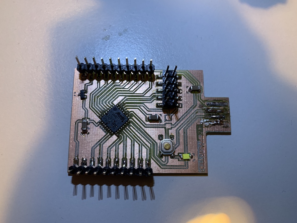
what hasn’t? until now all has worked, but there was a lot of trial and error to fabricate the pcbs with SAMD21, because of the size of connectors, required a vbit small enough to machine properly the PCB copper. Also the number of connectors and vias to rounte in the controller PCB was more challenging to do and smaller PCBs. In the end the controller to work properly needed some serial connector re-routed via coper cable and also 3.3v connection needed a bypass to work properly and provide power to ESP12s
What questions need to be resolved?
how to design a proper front suspension.
What will happen when?
project will have a 2nd iteration/version later
What have you learned?
I learned a lot, CNC, 3d Printing, laser cutting, design a circuits that have more components and connect wifi to serial and how to handle this in the software. Have learned how to assemble CNC machines, 3d Printer and vacuum bagging properly :) have a mini-fablab in the garage :D
Project Planning
| Fab Academy Week | Project related tasks | Date | Done |
|---|---|---|---|
| 1. Principles and practices | |||
| 2. Project management | |||
| 3. Computer Aided design | |||
| 4. Computer controlled cutting | design & cut chassi, maybe suspension arms for size fit/mockup | ||
| 5. Electronics production | design/mockup electronics | ||
| 6. 3D Scanning and printing | |||
| 7. Electronics design | design/mockup electronics | ||
| 8. Computer controlled machining | |||
| 9. Embedded programming | |||
| 10. Molding and casting | cast some gears, suspension arms or rims | ||
| 11. Input devices | test Time-of-Flight, accelerometer, gyro and gps sensors. build sensor board. | ||
| 12. Output devices | test brushless motor controll. build power distribution board. | ||
| 13. Applications and implications | Improve project concept and documentation. Iterate. | ||
| 14. Networking and communications | design and build and test communication board. I2C communication between boards. Communication Between phone and rc car via WIFI. | ||
| 15. Mechanical design | design front/back suspension, steering | ||
| 16. Interface and application programming | connect the phone with servo and motors. Design interface that could drive the car | ||
| 17. Machine design | automate steering | ||
| 18. Wildcard week | learn and work with composite. Design and build a rc car shell | ||
| 19. Invention, intellectual property and income | how is the project being shared? | x | |
| 20. Project development |
Development by week topic
3. Computer Aided design
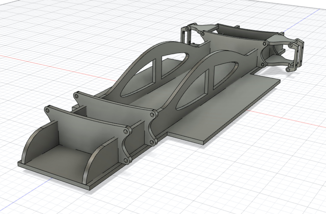
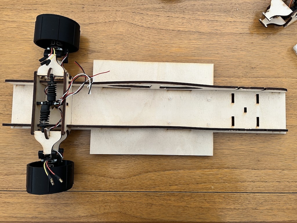
*** Chassi design: *** The main idea was to use plywood to make the most of the chassi parts. 1 Plywood sheet, cutted in the laser, could create 1 chassi. So the design took this into account. The design was influenced also by press-kit features. Did try to make the most of it without requiring screws or glue.
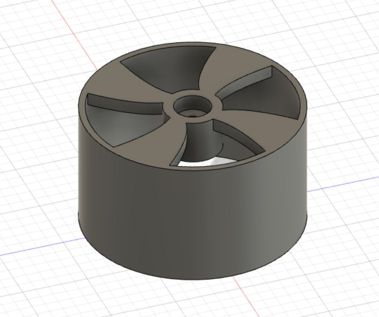
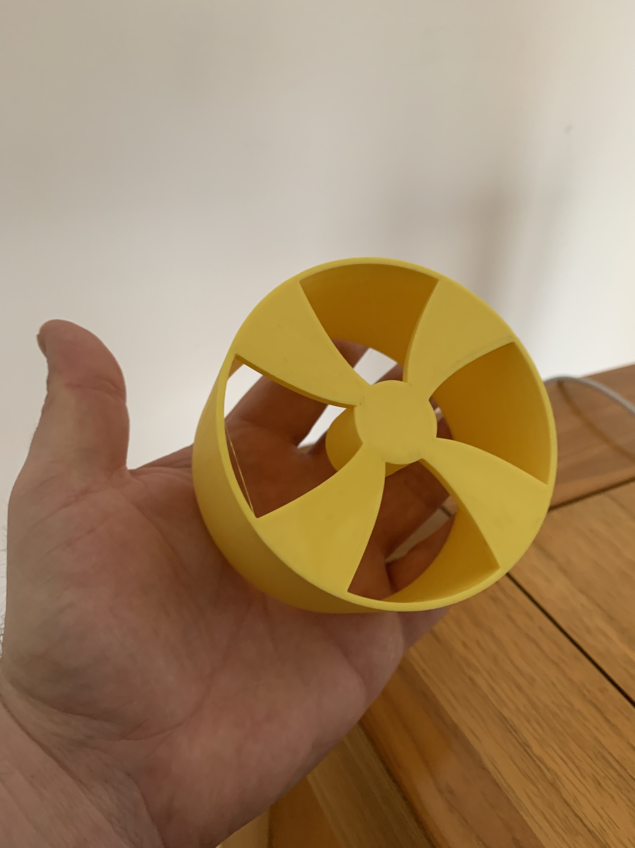
Prototype of the car wheel.
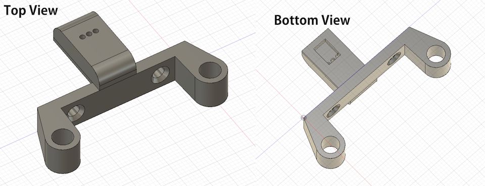
Motor mount to suspension.
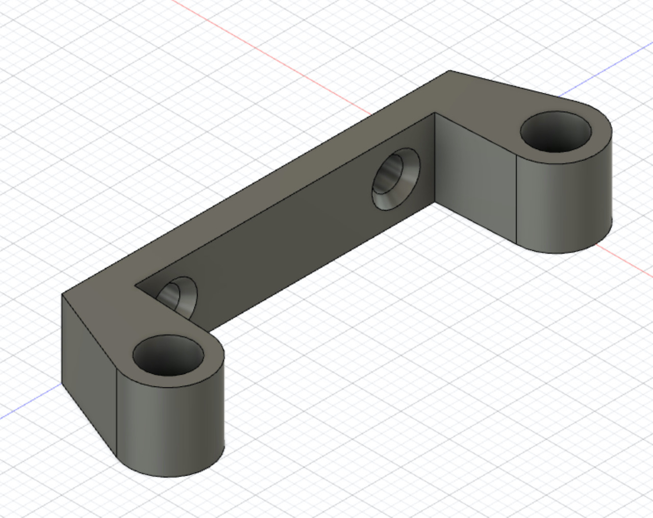
with support for hall sensor
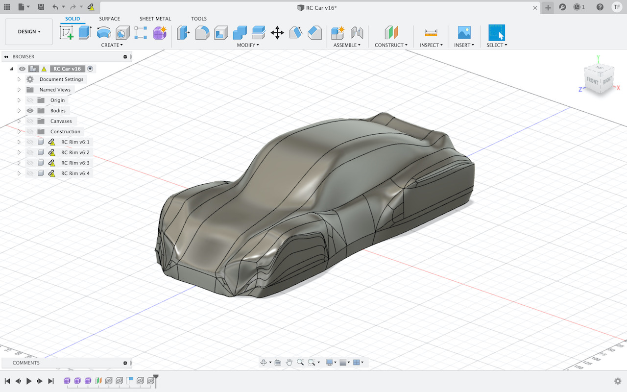
Shell design
Testing ball joints
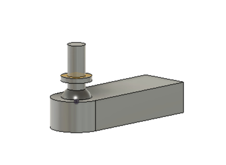
This was a last design update, because of the steering design of the car that proved to be more difficult to do than expected. Rack and pineon connection to servo and a suspension moving up and down doesn’t work ok with joints that have limited freedom to move or follow suspension travel movements with steering rack moving from side to side. So the ball joints came in later as a new way to connect sterring and front wheel hubs.
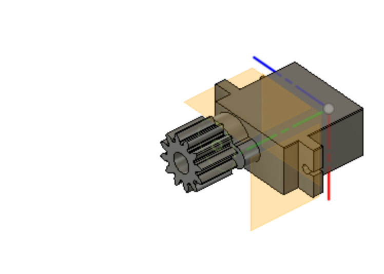
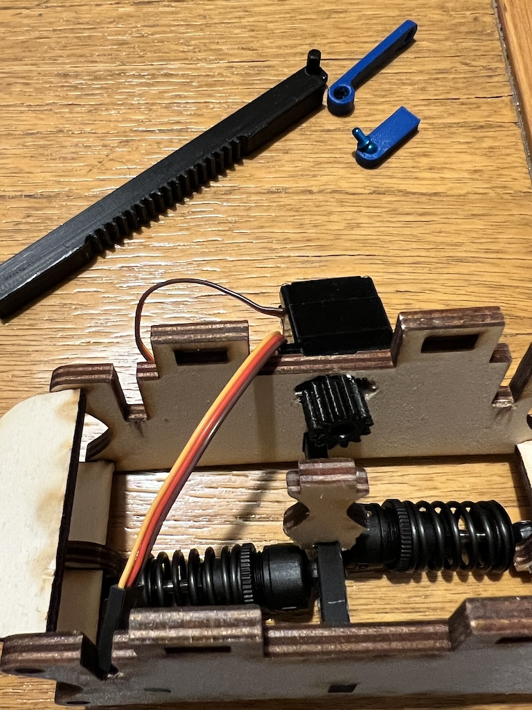
Steering servo pineon/gear
Links
4. Computer controlled cutting (Chassi and suspension)
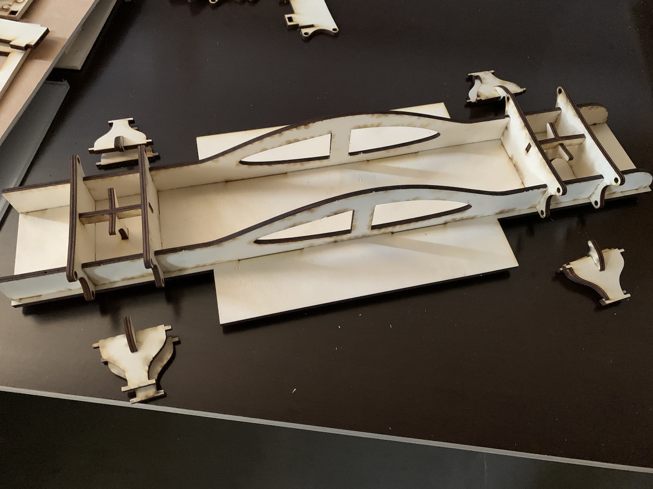
From the chassi design exported the dxf files to use in the laser cutter.
For the project most of the chassi/frame are in plywood. 1 or 2 sheets of plywood woulld allow to build the chassi of the car.
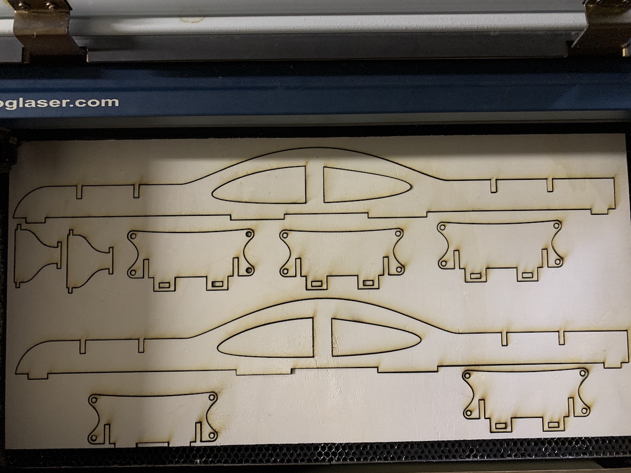
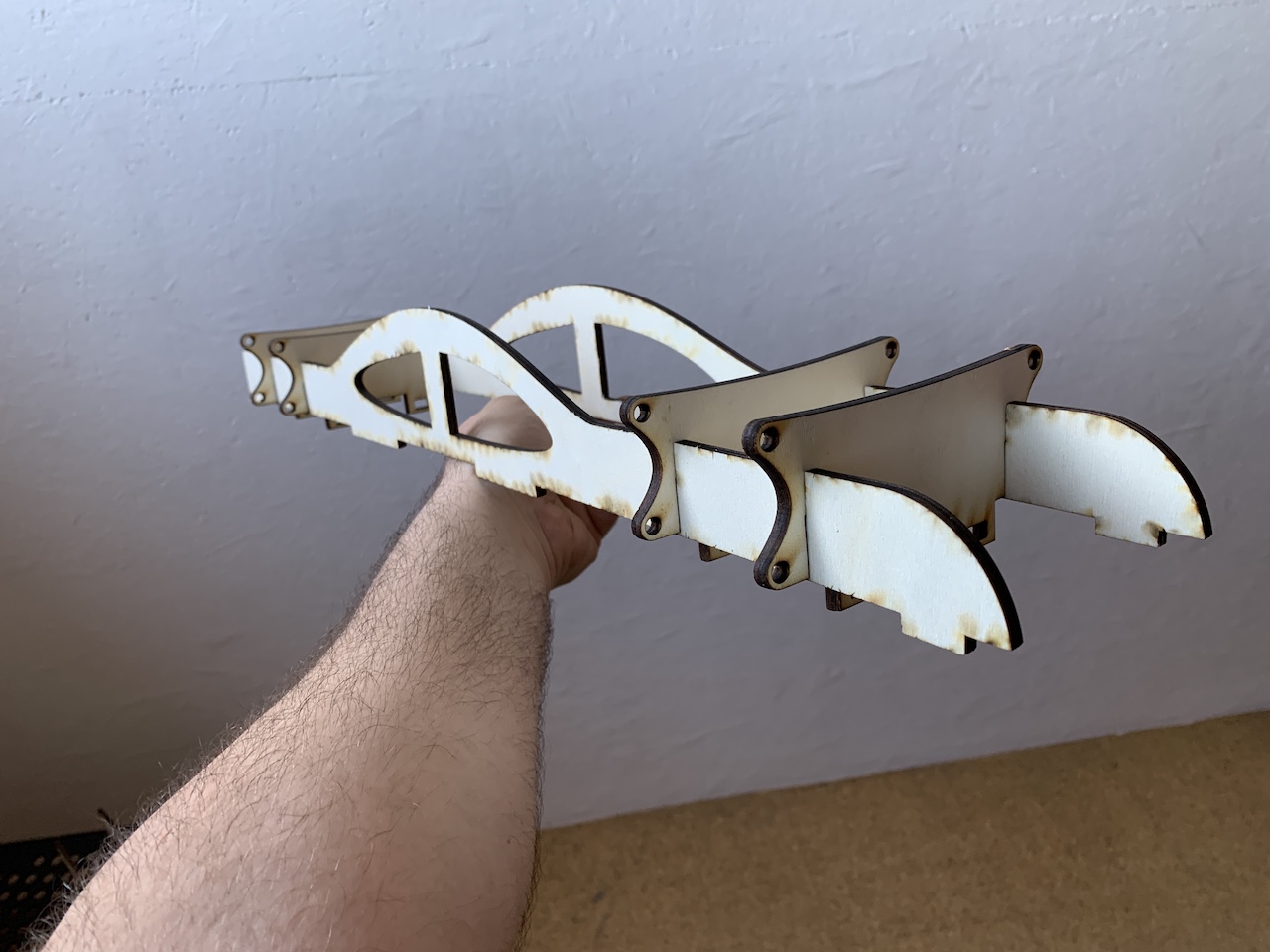
The first test to see if all parts fit together.
6. 3D printing
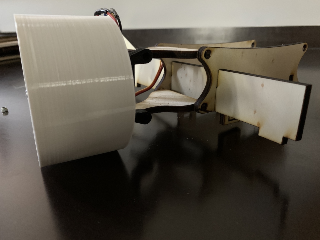
Printing and testing wheel/rim.
Testing how it fits the motor mount point (in black) with the suspension arm.
3D printed Ball joint (that was being tested for fittement and movement), Steering rack and pineon/gear (in servo to turn wheels left/right)
7. Electronics design
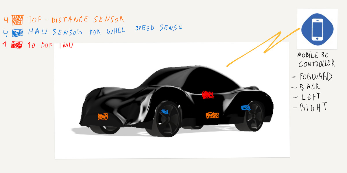
For electronics design have mocked up / brainsormed how the several parts of the car would be controlled and how it should work.
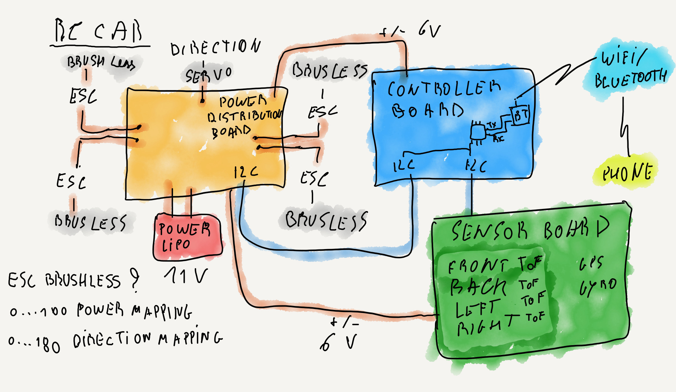
Idea for 1st objective is to use mobile phone app to controll the Car via wifi connection. Then this could evolve into 2nd and 3rd objectives to eventually have autonomous driving.
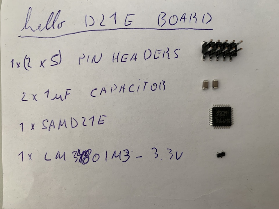
SAMD21E Hello board
Before milling and stuffing the project controller board, have decided to make the ATSAMD21 hello.D21E board. This allowed me to test the use of ATSAMD21 by itself in a PCB without other components and gain experience with it.
PCB Design & Milling
Started to learn and design PCBs with EasyEDA. Similar to Eagle but more easy to search/add parts.
Design Rules:
- Units: mm
- Track width: 0.4 mm
- Clearance: 0.3 mm
- SAMD21E17 pads, edited their width to 0,55 mm
EasyEDA tips
- Shift + B , rebuilds copper areas.
- Used copper area icon to add GND to top layer
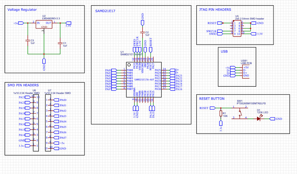
Yes, added a reset button and a led to turn on when button is pressed.
Files: Project_SAMD21 Hello Board.zip
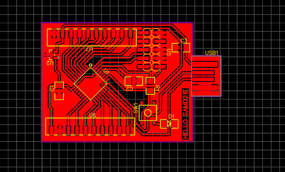
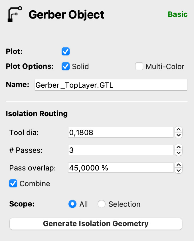
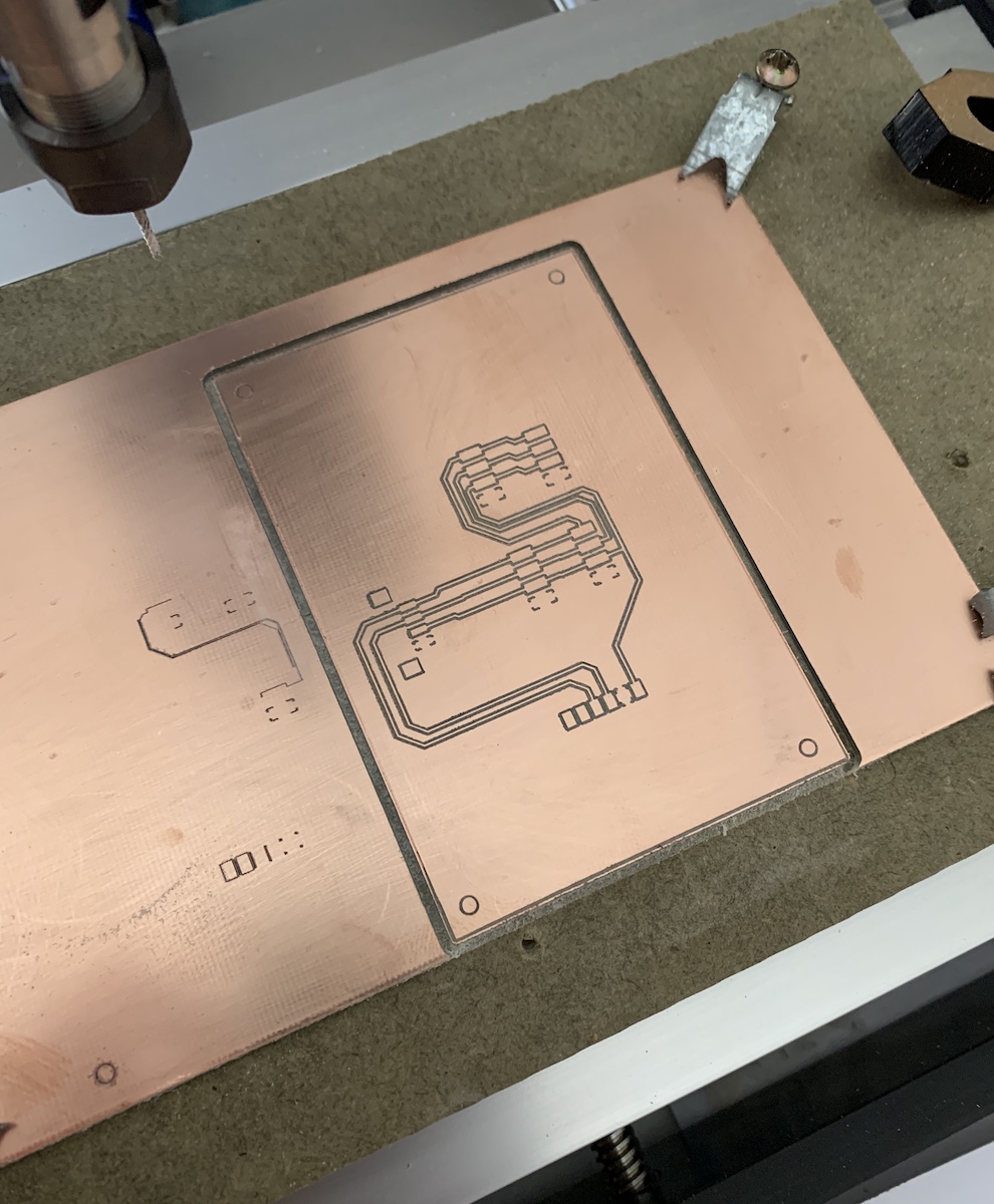
For the milling, generated “PCB Fabrication File” with EasyEDA and used FlatCAM to open gerber file with board top layer to then generate the isolation paths and pcb cut out.
Isolation configuration:
Used a Cirqoid V bit for the milling:
- dia: 0,1
- angle: 60 deg
Used FlatCAM calculator tool to calculate the dia of the v bit at 0,07 cut depth.
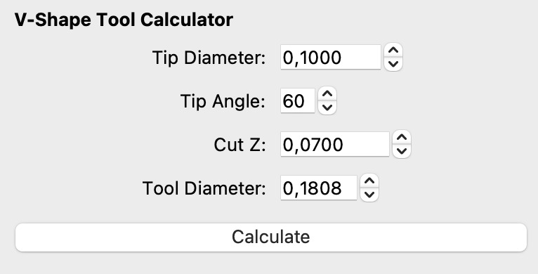
Used tool diameter in the isolation routing config
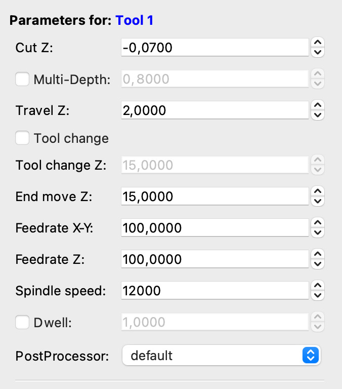
Then saved the CNC code and opened it on Chilipeppr. Did the auto-level probe and run, sent the auto-level gcode to workspace, and milled the pcb. After that did generate the cutout and milled it also with Chilipeppr.
and stuffed
Links
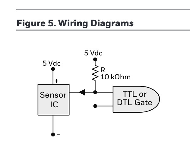
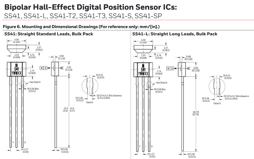
Bipolar Hall Sensor SS41
This hall effect sensor is triggered by magnetic field from permanent or electro magnets and are designed to respond to alternating North and Sourth poles. It can be used on several applications like: Sensing Speed and RPM (revolutions per minute); tachometer; flow-rate sensing; brushless dc (direct current) motor commutation; motor and fan control; robotics control; electric window lift; medication dispensing control, etc.
| Characteristics | |
|---|---|
| Vdc | 4.5 to 24 v |
| Output | Open collector |
Links
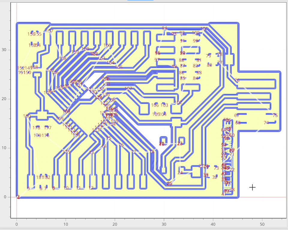
RC Car
Design Rules:
- Units: mm
- Track width: 0.4 mm
- Clearance: 0.3 mm
- SAMD21E17 pads, edited their width to 0,55 mm
- V bit dia: 0.2210
- z depth: -0.08
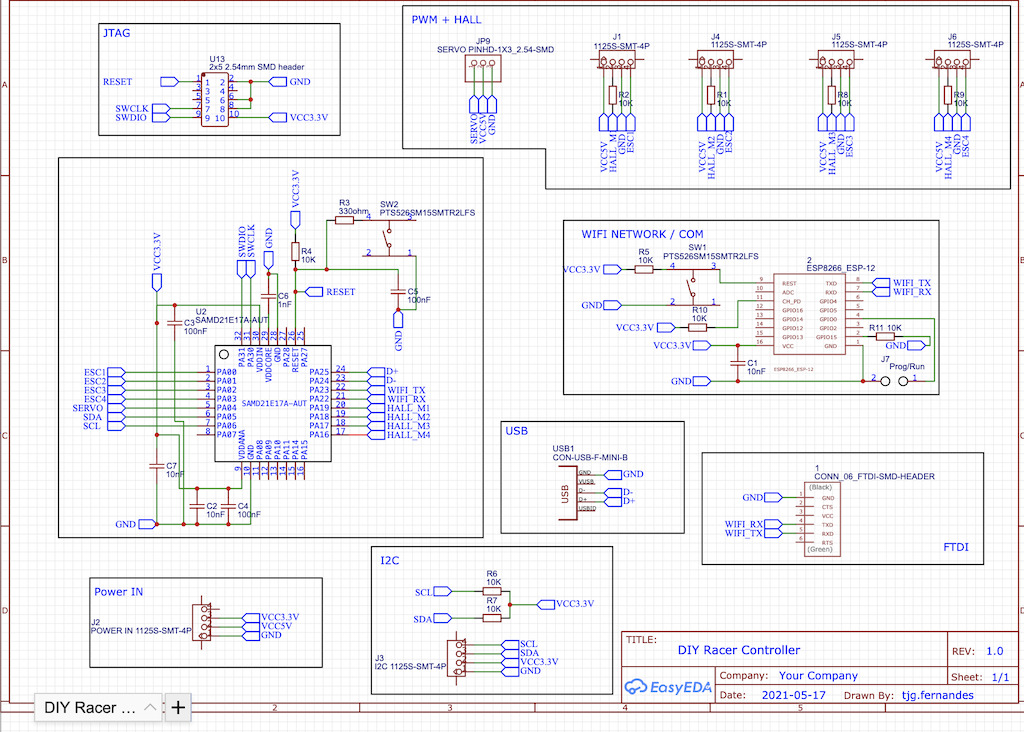
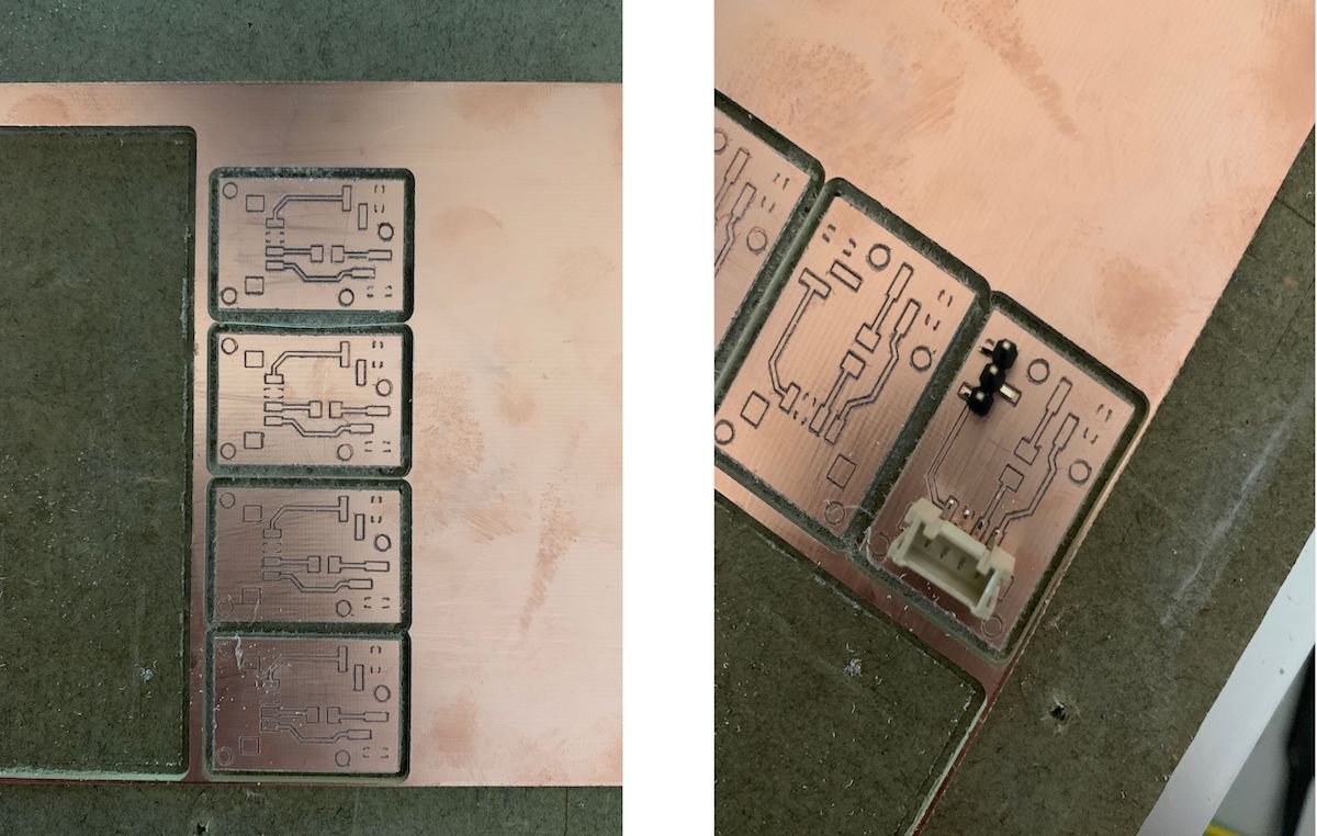
So by design, instead of having everything in one PCB, i designed 3 main PCBs to be the base of the RC car. Power PCB, Controller PCB and the Sensors PCB. These would allow to controll a direction Servo, 4 ESC/Brushless motors and 4 hall sensors (to sense wheel speed), connected by an ESP12-S over wifi to a mobile app. By having the PCBs separated it’s relatively easy to redesign/improve/change just one of those. Examples of changes: controller PCB with another microcontroller; Radio communication instead of Wifi; 9v power regulator; Lipo battery low voltage warning beeep/buzzer, etc. Have designed 1 more PCB, the motor PCB, because after noticing that there were a bit of wires going into each wheel i changed the connection to use 4 wire Grove connectors to connect to each motor pcb (a more “clean” solution). Then on each wheel the respective hall sensor and motor esc connects to this Motor PCB.
Power PCB
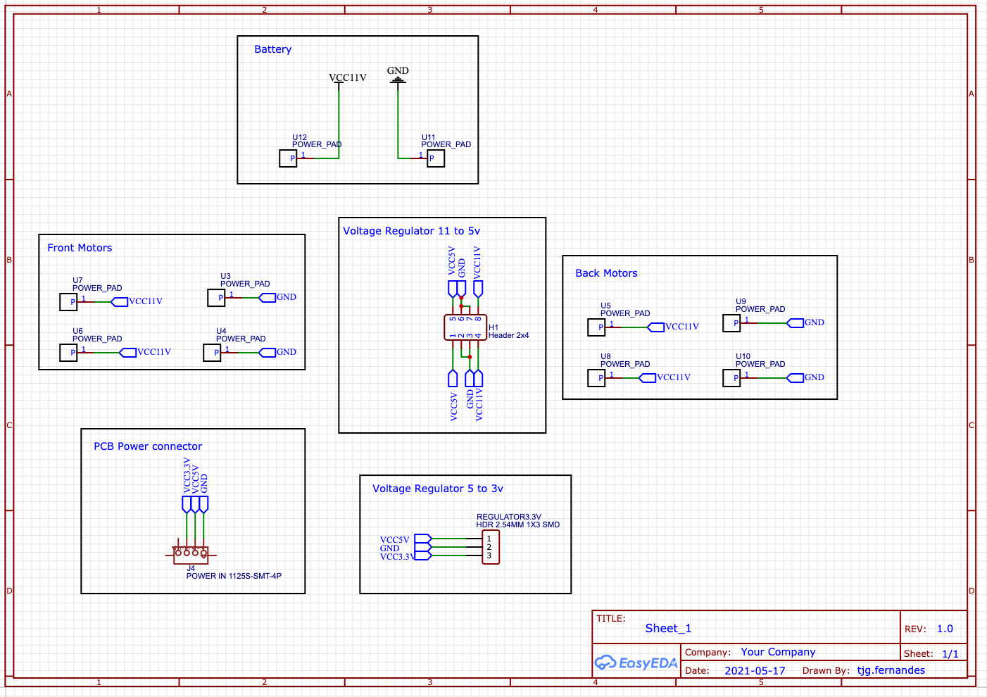
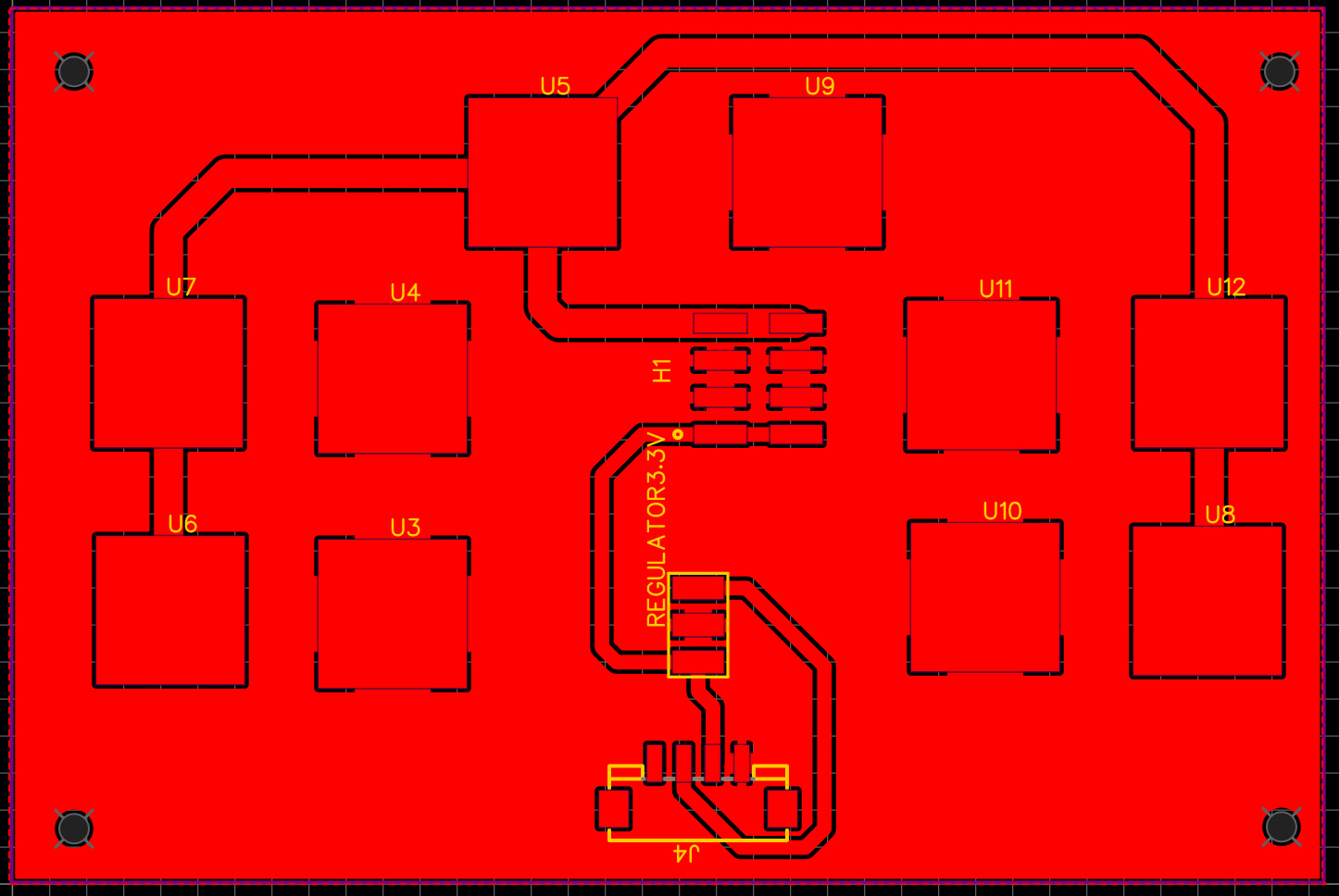
most of the times while choosing parts for the PCB i choose them wrong because of the different sizes that exist for PCBs components (SMD/SMT/etc.) So Marius reminded me that a good way to test the pcb design is to export image and print the circuit in paper to test sizes.
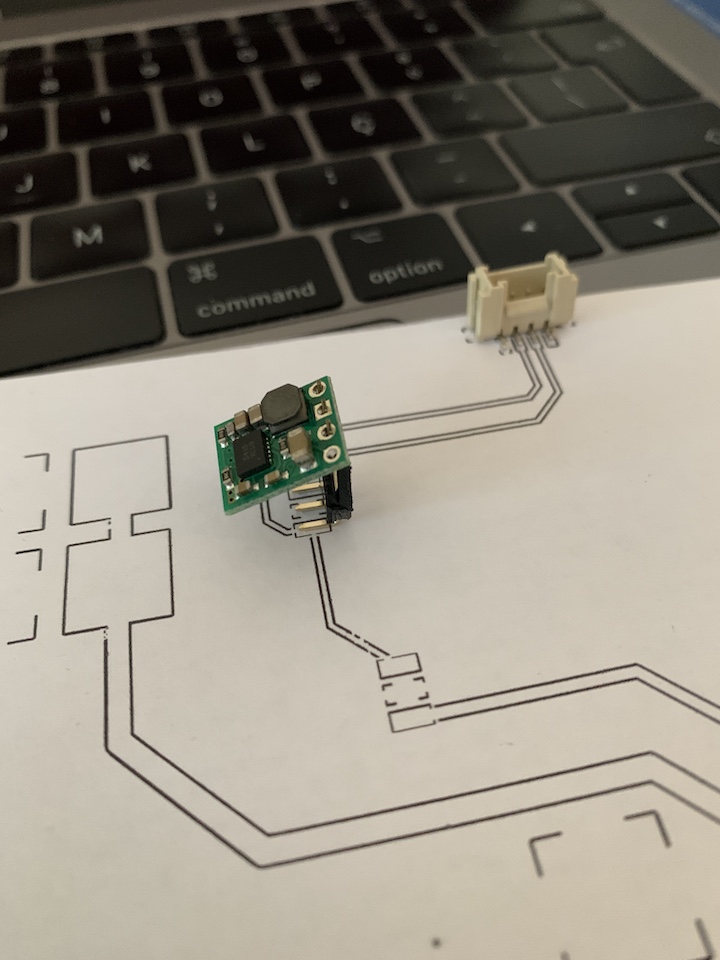
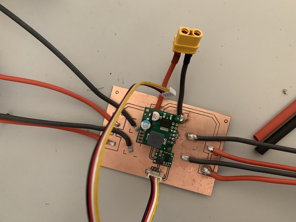
Files: EasyEDA_Project_DIY_Racer_Power.zip
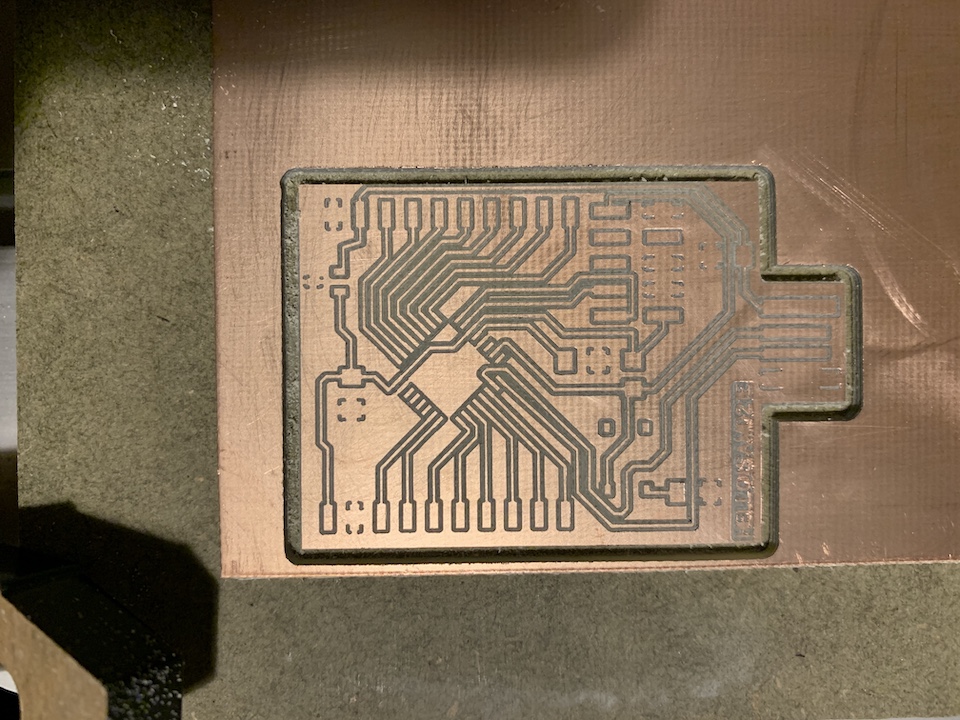
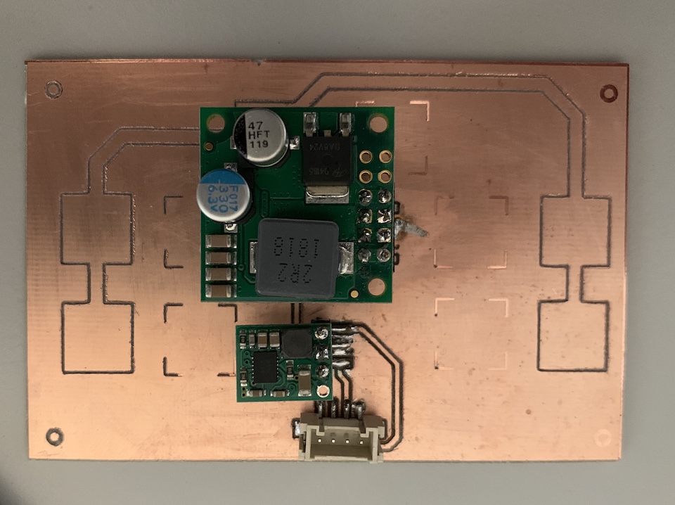
Controller PCB
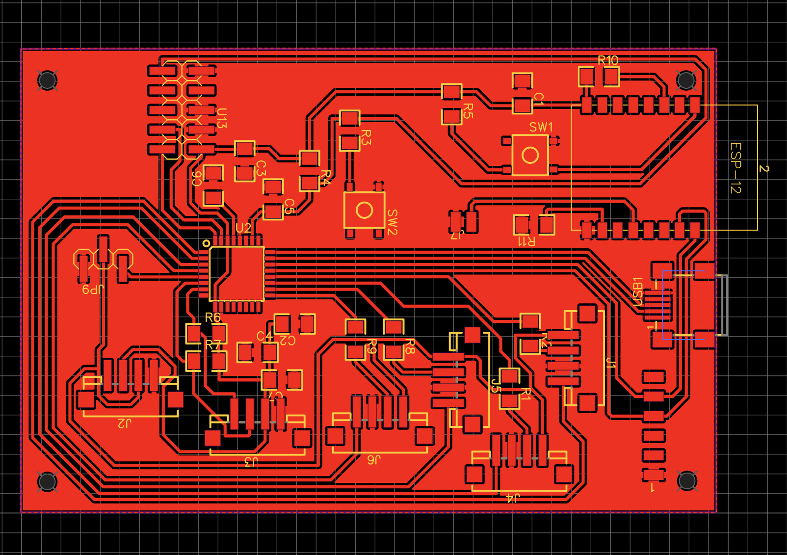
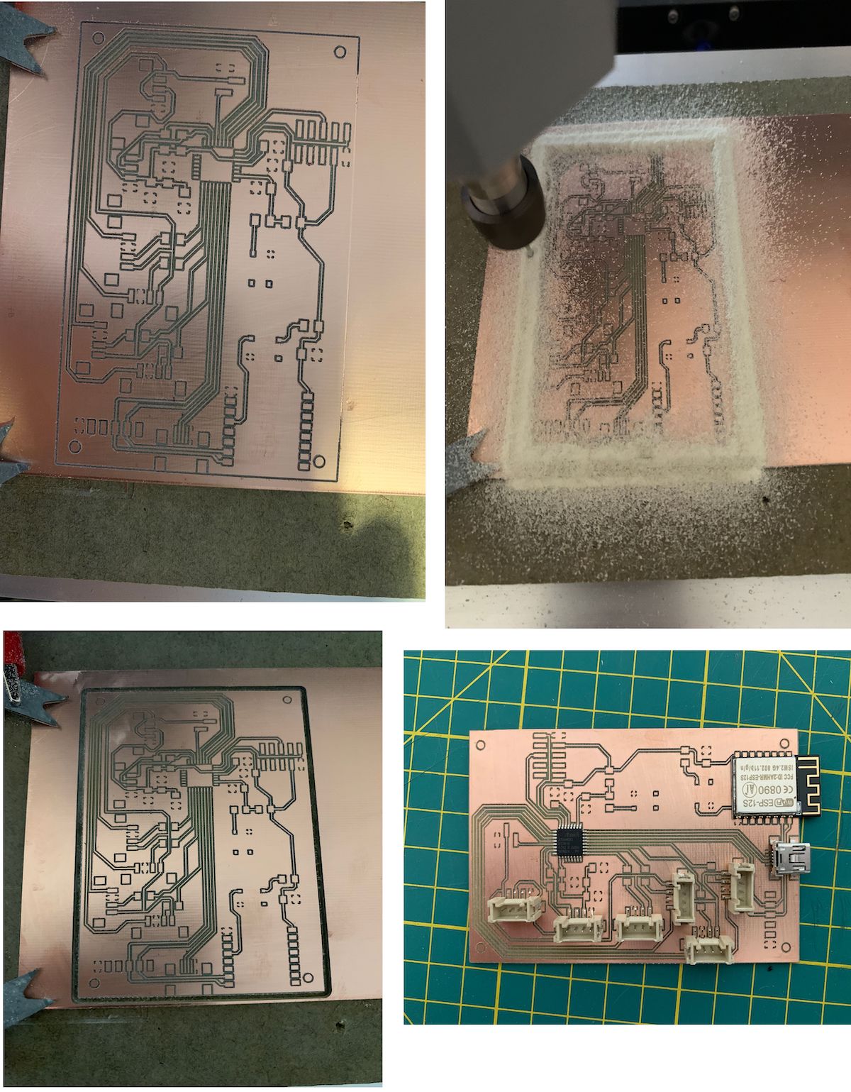
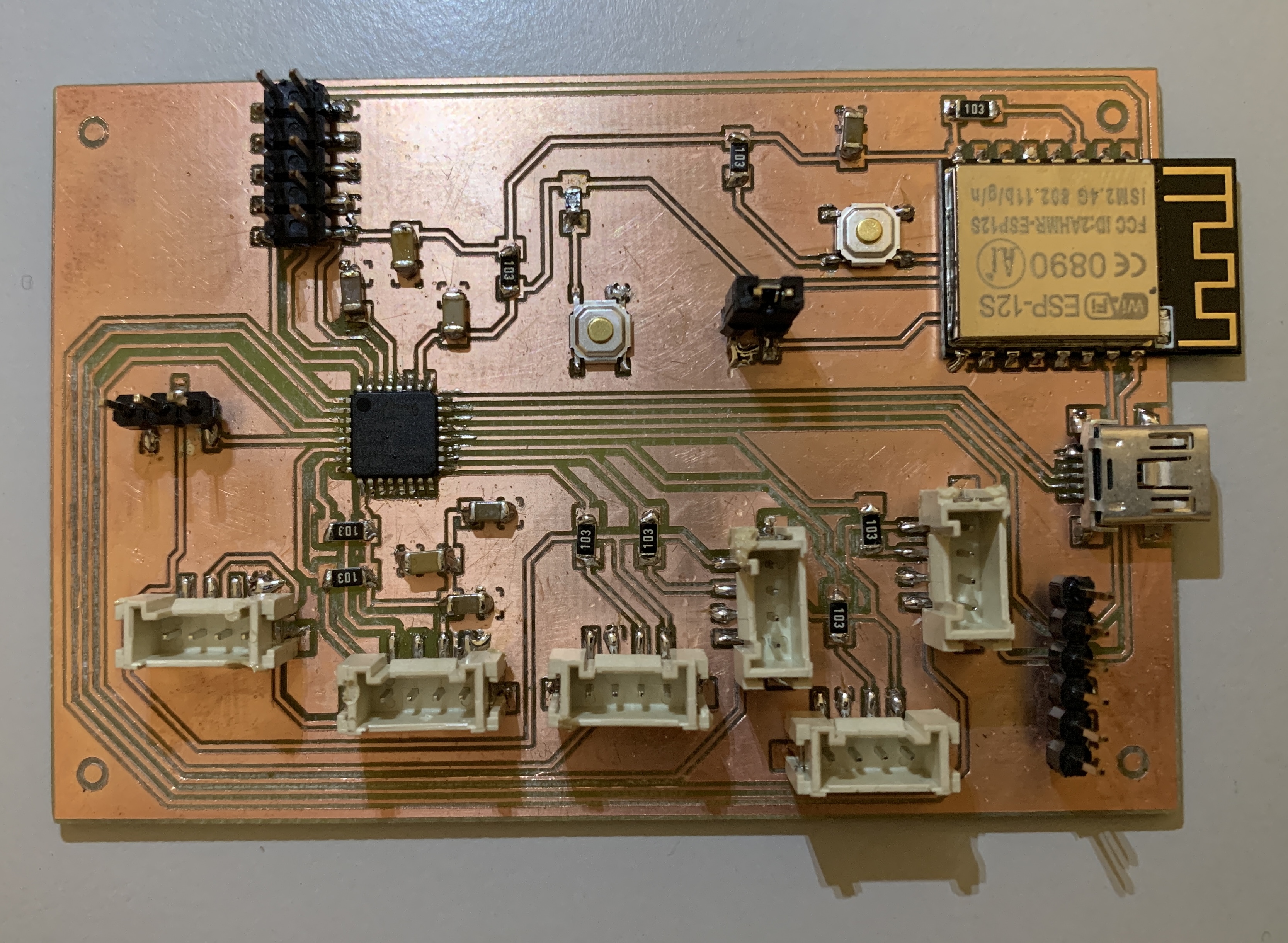
PCB stuffing
Files: EasyEDA_Project_DIY_Racer_Controller.zip
Sensors PCB
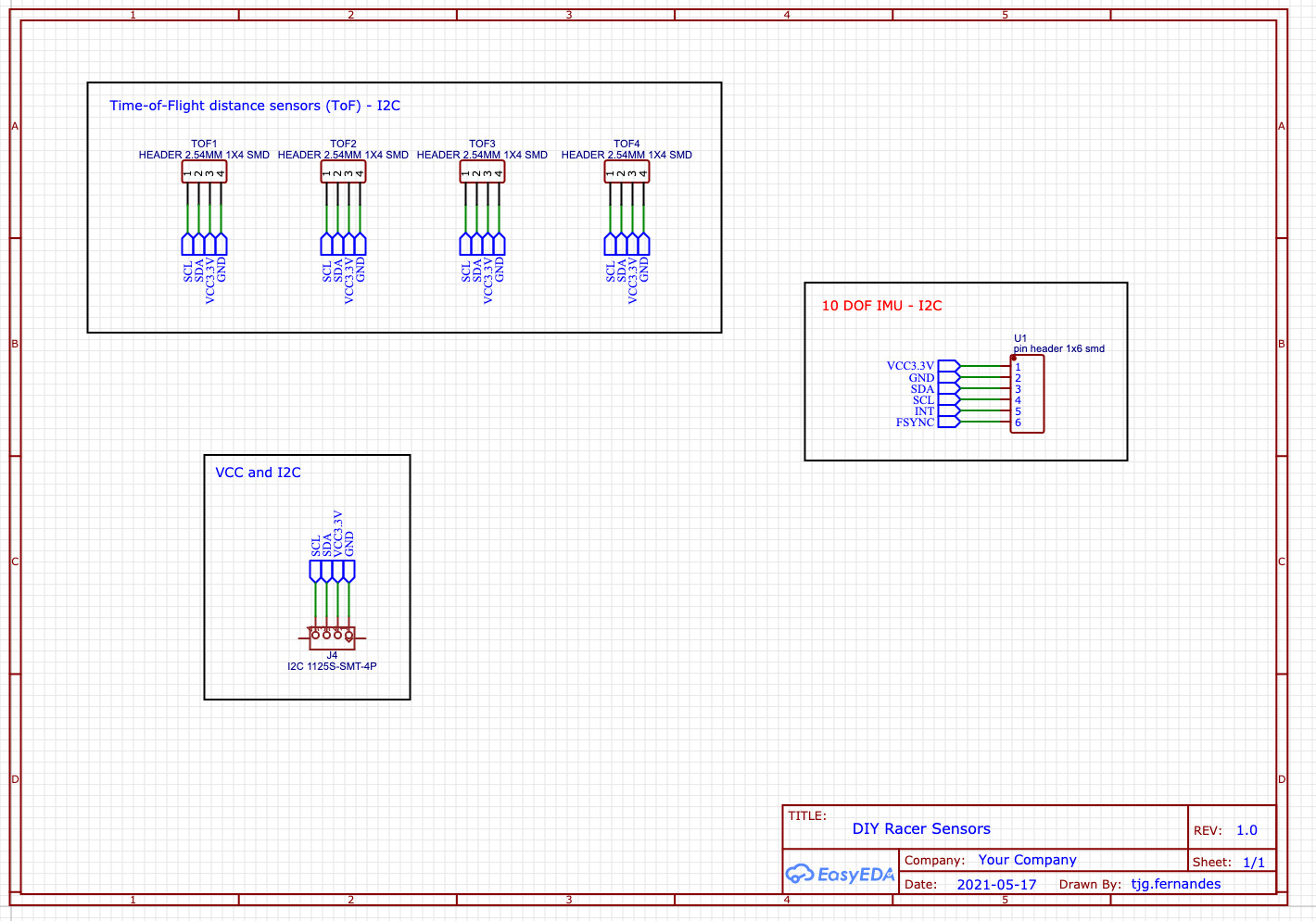
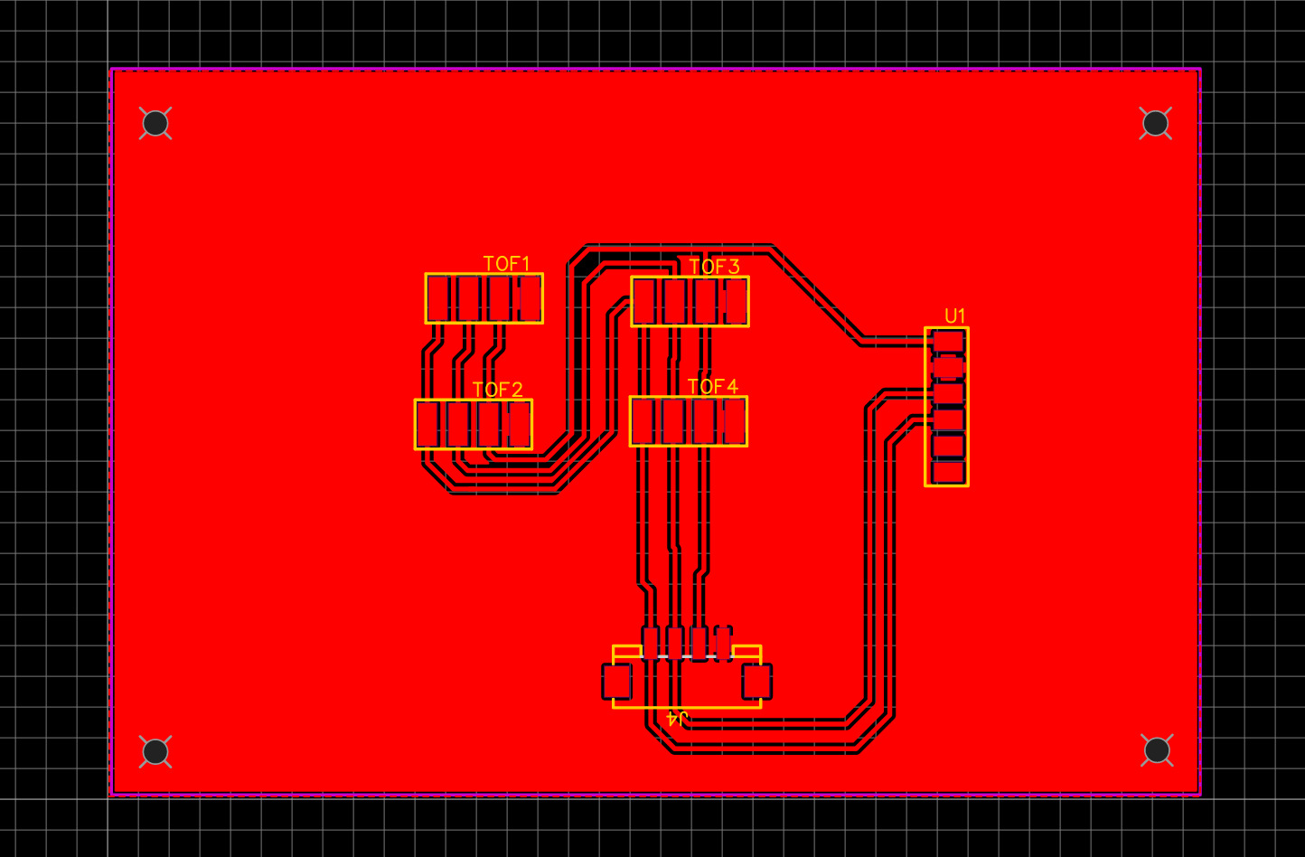
Files: EasyEDA_Project_DIY_Racer_Sensors.zip
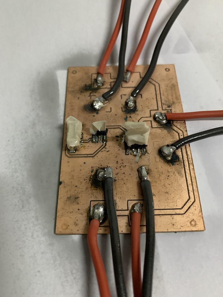
Motor PCB
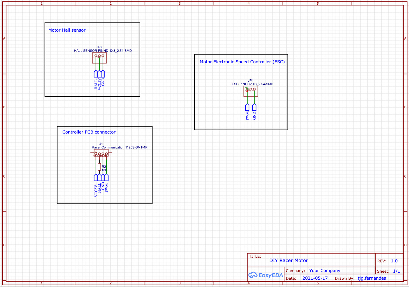
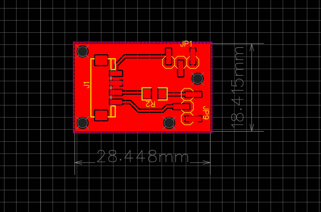
Files: EasyEDA_Project_DIY_Racer_Motor.zip
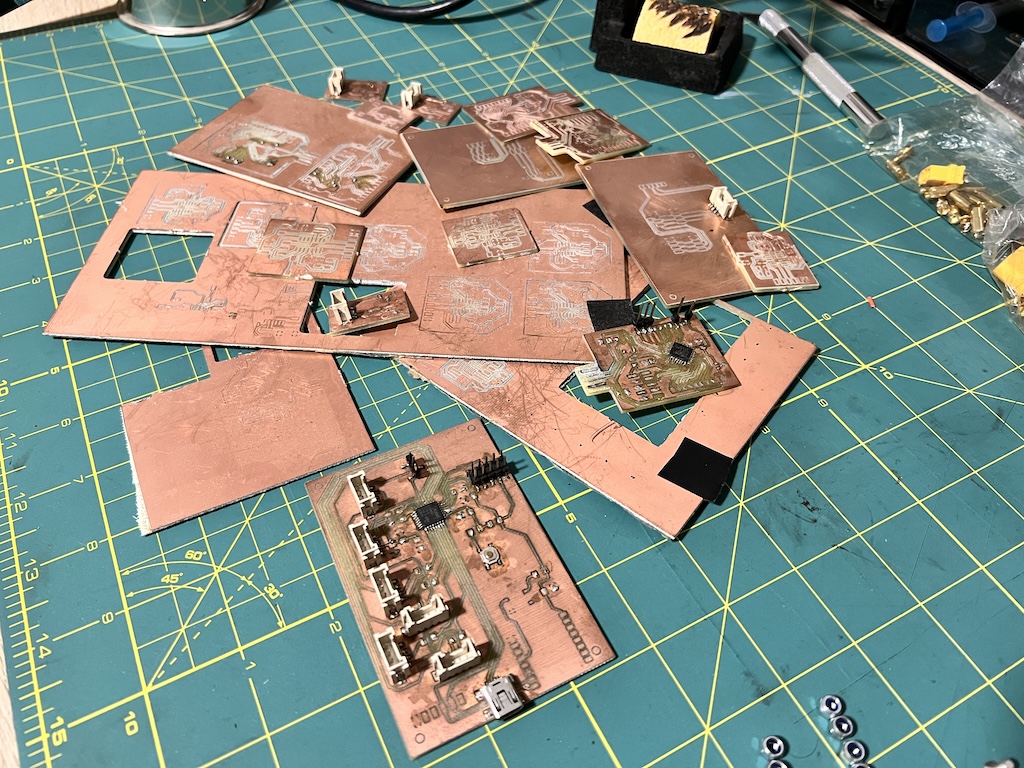
Some failures
9. Embedded programming
Programming SAMD21
Following MT-D21E_User_Guide.pdf and MattairTech ArduinoCore-samd, configured Arduino IDE on Mac to allow to compile Neil hello.D21E.echo.ino.
Notes
* Use Arduino IDE 1.8.15 or later
* add into Arduino IDE -> Preferences -> Additional Boards Manager URLs. https://www.mattairtech.com/software/arduino/package_MattairTech_index.json
* Install board MattairTech SAM D|L|C core for Arduino
ATSAMD21E17A-U
* ATSAMD = General Purpose Microcontroller
* 21 = Cortex M0 + CPU, Basic Feature Set
* E = 32 Pins
* 17 = 128 Kb Flash memory
* A = Default Variant
Bootloader
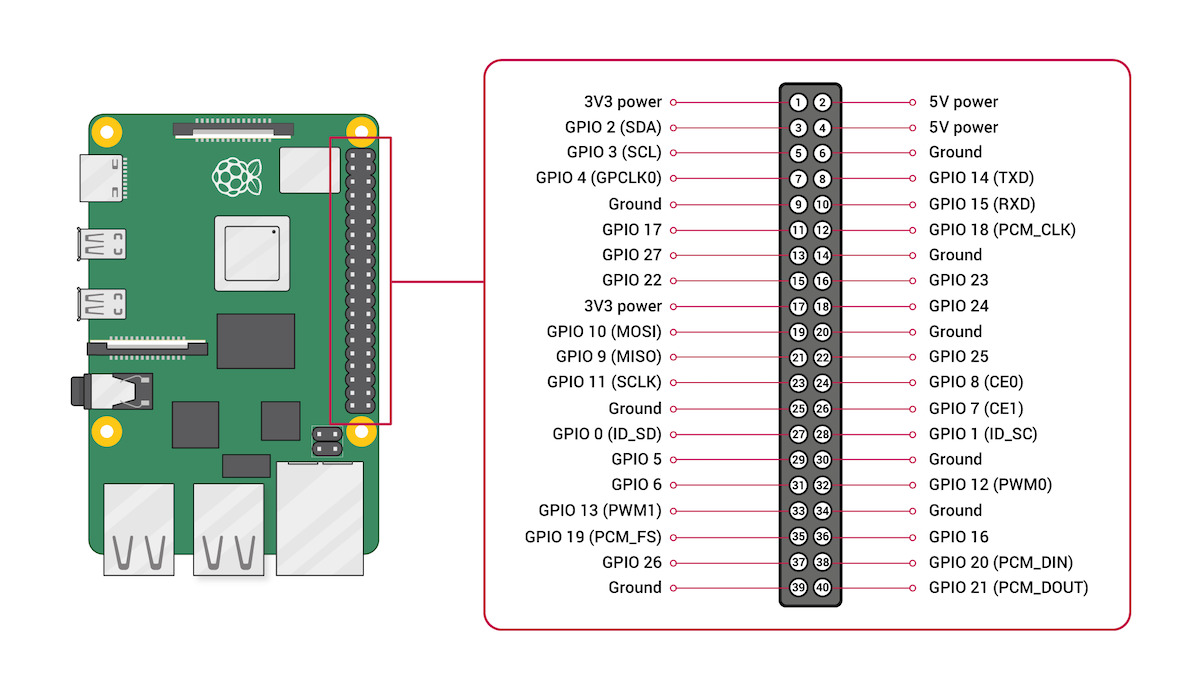
To flash the SAMD21 with the required bootloader so that Arduino IDE could be used to program it, i used a Raspberry PI 3 B+. Followed Programming Microcontrollers using OpenOCD on a Raspberry Pi to use Open On-Chip Debugger to flash the bootloader via Raspberry PI i/o using JTAG.
Once Open On-Chip Debugger was installed on the Raspberry pi, connected the GND (PIN 6), Reset (PIN 12, GPIO 18), Clock (PIN 23, GPIO 11) and SWDIO (PIN 24, GPIO 8) to the SAMD21 Hello board PCB
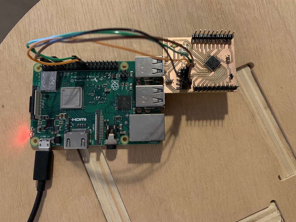
tested if the JTAG connection between the board and the raspberry pi was working
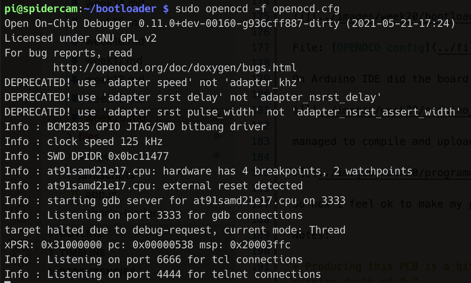
File: OPENOCD test config
and flashed the sam_ba_MT_D21E_rev_B_SAMD21E17A.bin into samd21
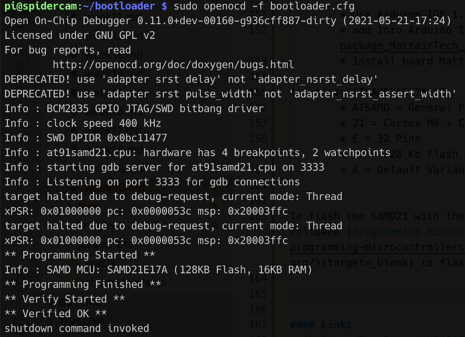
File: OPENOCD bootloader config
hello.D21E.echo.ino
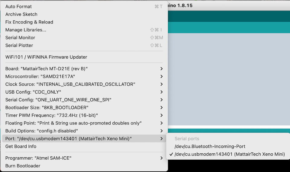
On Arduino IDE did the board setup
managed to compile, upload and execute Neil hello board example :)
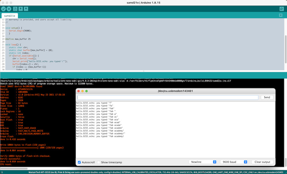
So now i feel good to make my project controller board.
Notes:
- Producing this PCB is a bit more work and required me to use a 0,1 v bit and calculate in a more precise way the bit width for the cutting depth of 0,7.
- So this was the success case of some milling failures, mainly because of the SAMD21 pins are smaller.
- Soldering the SAMD21 requires a bit more patience also :)
Links
- Programming Microcontrollers using OpenOCD on a Raspberry Pi
- MT-D21E User Guide
- atsamd11 hello-world
- Fablab Kamakura Support Documents - ATSAMD
Testing Controller + Sensor PCB
Testing the controller board connected to direction servo and Sensors PCB to allow to control the ESC/Motor.
Bipolar Hall Sensor SS41
Testing the sensor with an Arduino Uno, it works and senses the magnets of the brushless motor.
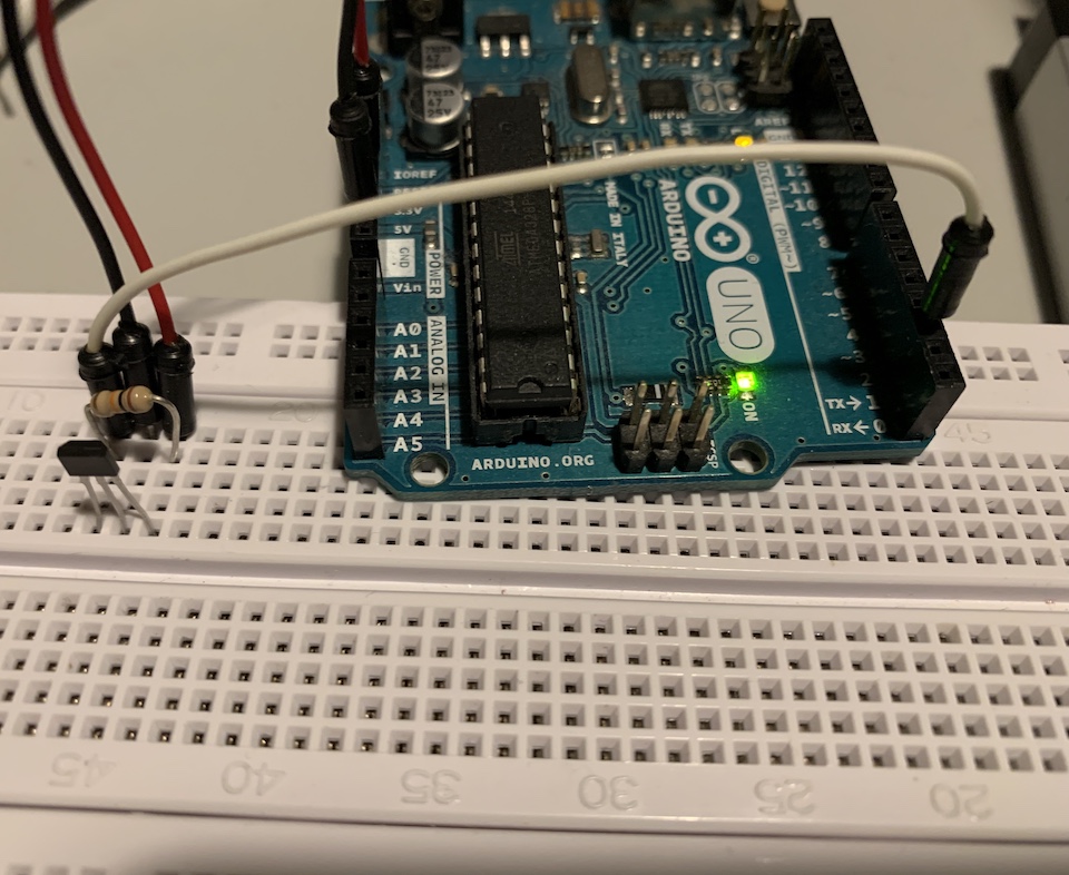
Then mounted the sensor in the whel with the 3D printed motor suspension mount.
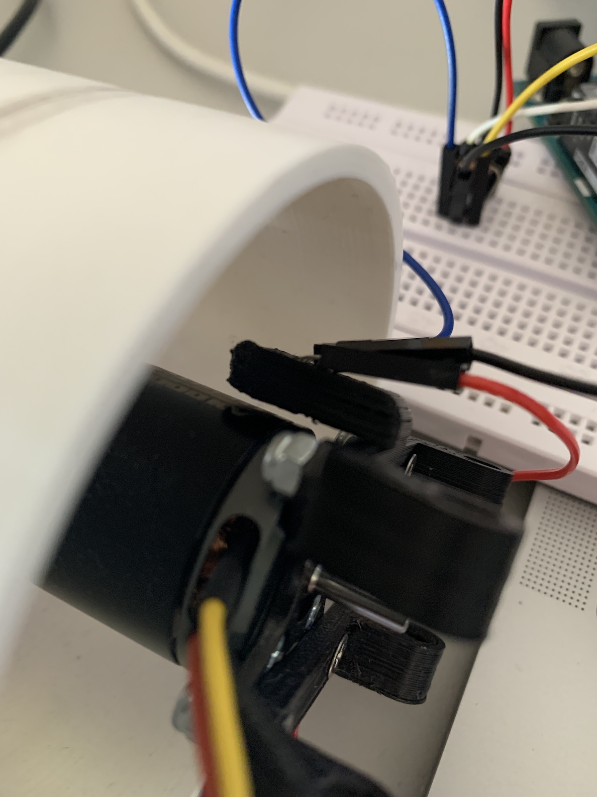
You can see the whel turning and sensor detecting the movement of magnets.
Links
(old) Eagle Files and Libraries
Note
These are here just to keep track/history, these were used on 1st designs with Eagle, but not used with EasyEDA
Files: Eagle DIY Racer
- atmel.lbr
- pinhead-2.lbr
- OPL eagle library
- ESP8266-ESP12.lbr
- Microchip SAMD21
- STMicroelectronics IMU LSM6DSMTR
- STMicroelectronics VL53L0CXV0DH/1
12. Output devices
The controll of the servo and brushless motors follow the experiments i did on Output devices week. So after developing the mobile app and software for the ESP12S and SAMD21 i tested all togheter by connecting the controll board with a battery, communication board, sensors board, a servo and a brushless motor.
14. Networking and communications
On Networking and communications i used a ESP8266 via WIFI and using IP and HTTP for communication. When designing the final project board i wanted to also have communication via wifi, so incorporated a ESP12S in the PCB. This ESP would receive the wifi communication and send any data to SAMD21 using Serial communication in between.
To connect via WIFI i read several examples and ended up using esp8266wifi udp-example, because i wanted to test UDP/IP between mobile app and car controller board (ESP12s). Idea was to send a simple “protocol” string with data to ESP12S, that would forward to SAMD21 to then set the servo PWM value and also PWM for motors ESCs. The string for now is, for example, “S:1200_D:1500\n”. 1200 and 1500 are the respectively the direction servo PWM value to be set and the PWM value to set on all 4 motors.
For the SAMD21 the job is to check available data to read from Serial, parte the values, update direction, speed with respective PWM values and finaly write back those values (eventually with more information later like distance sendors values, hall sensor values, etc.)
For the mobile application, please check Project Development page related section
16. Interface and application programming
The mobile app was developed using Flutter. I had explored it on Interface and application programming week, so followed same approach with some updates. To controll the car i used a knob interface using Dart control_pad package that allows to move left, right to steer and up/down to accelerate/slow down.
This is how it looks.
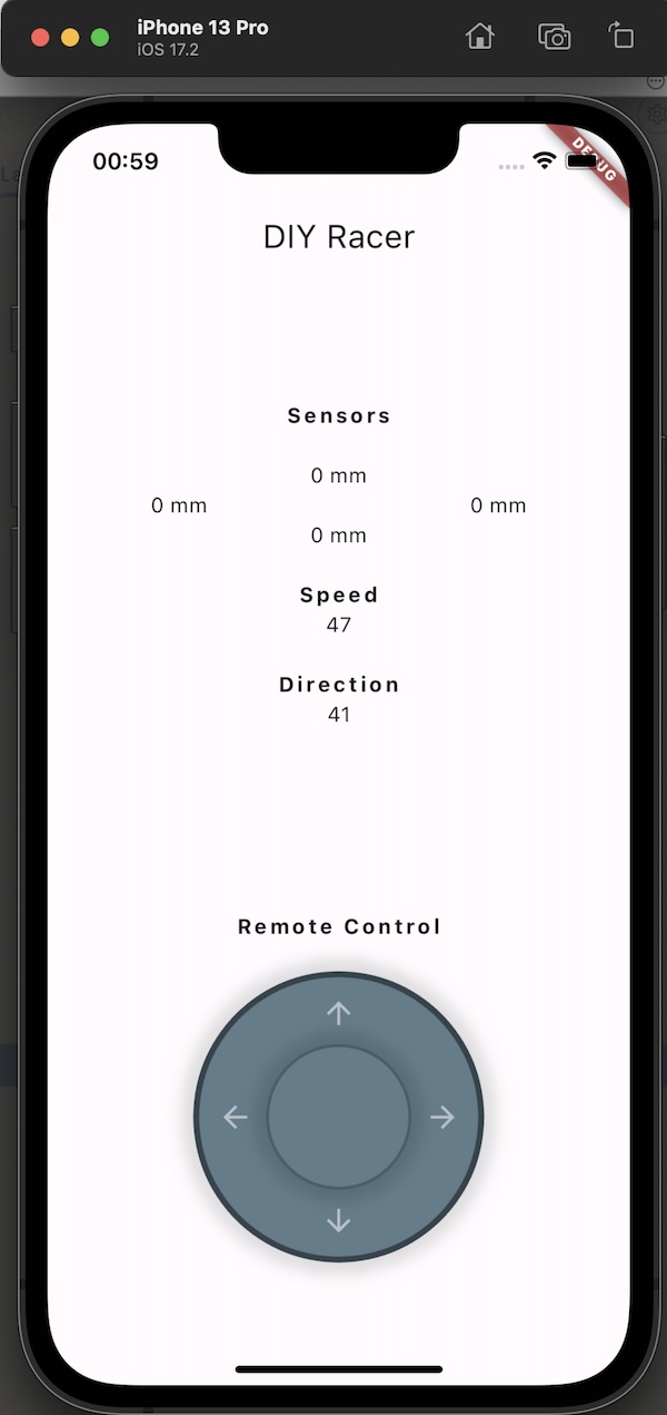
It allows user to controll the car with the joystick and have some information about the car.
The way it works for now is via IP, so it knows the IP address of the car and sends UDP data packets to it following the simple protocol string “S:1200_D:1500\n” with the values are updated via the joystick movement to turn left/right or up/down to just accelerate/slow down.
TODO: add link to mobile app code
18. Wildcard week (Design & Composite)
The design process is documented in the Wildcard week.
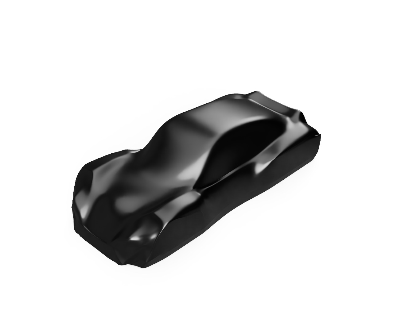
Render to check how it could look with the wheels on.
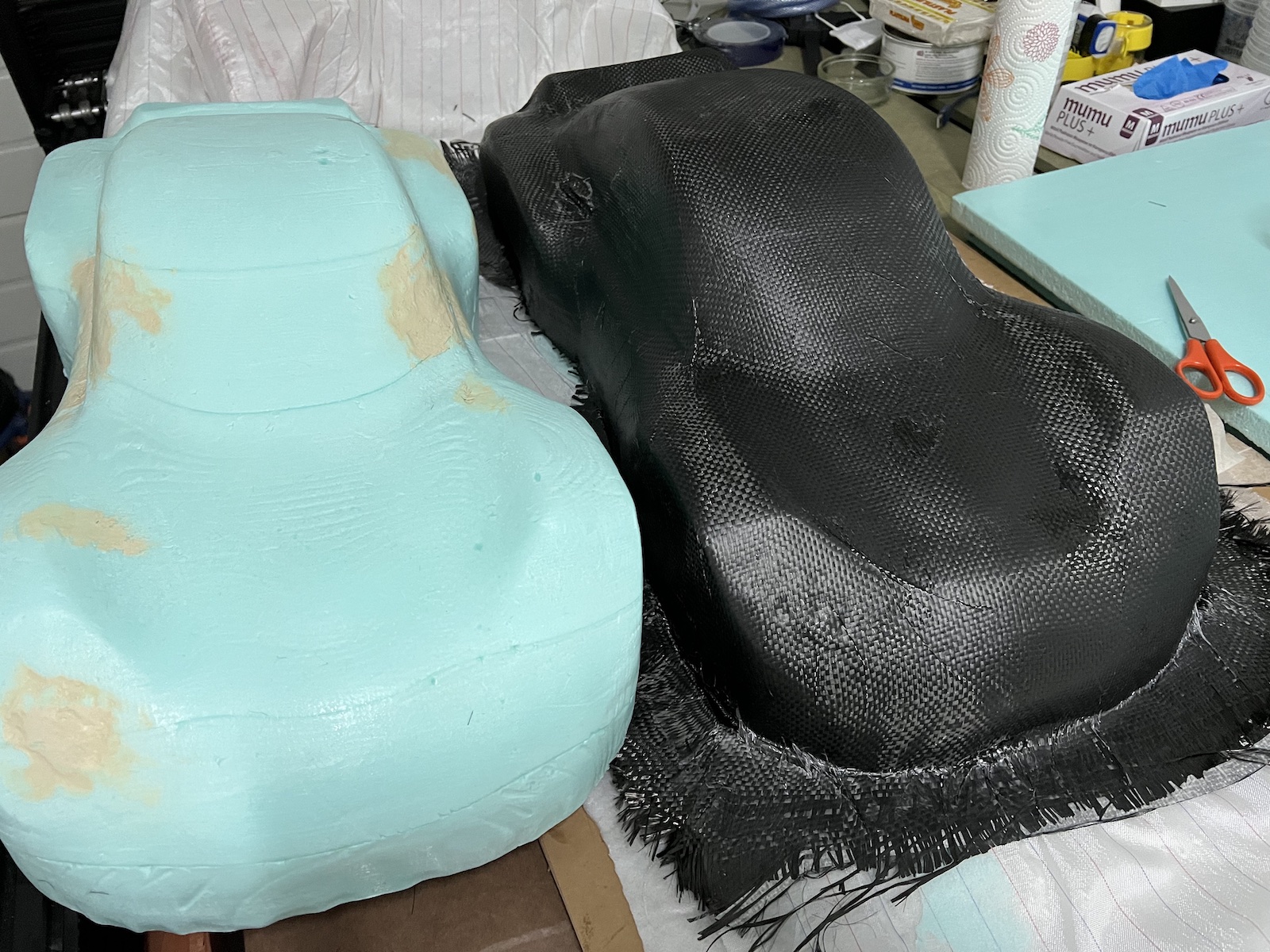
The Hero shot showing the created mold and the car shell side-by-side.
Please check complete steps/documentation in the Wildcard week.
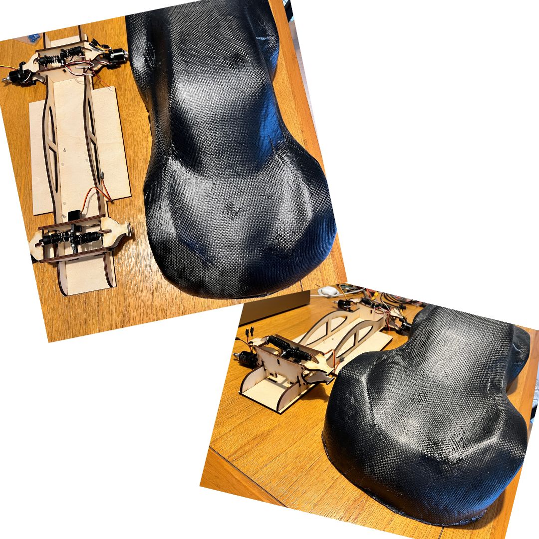
Looking better after some trimming of carbon fiber excess :) It fits with the chassis!
Project Parts Assembly
Chassi with back suspension with 2 motors. Use nylon screews to attach the pcb to the chassi.
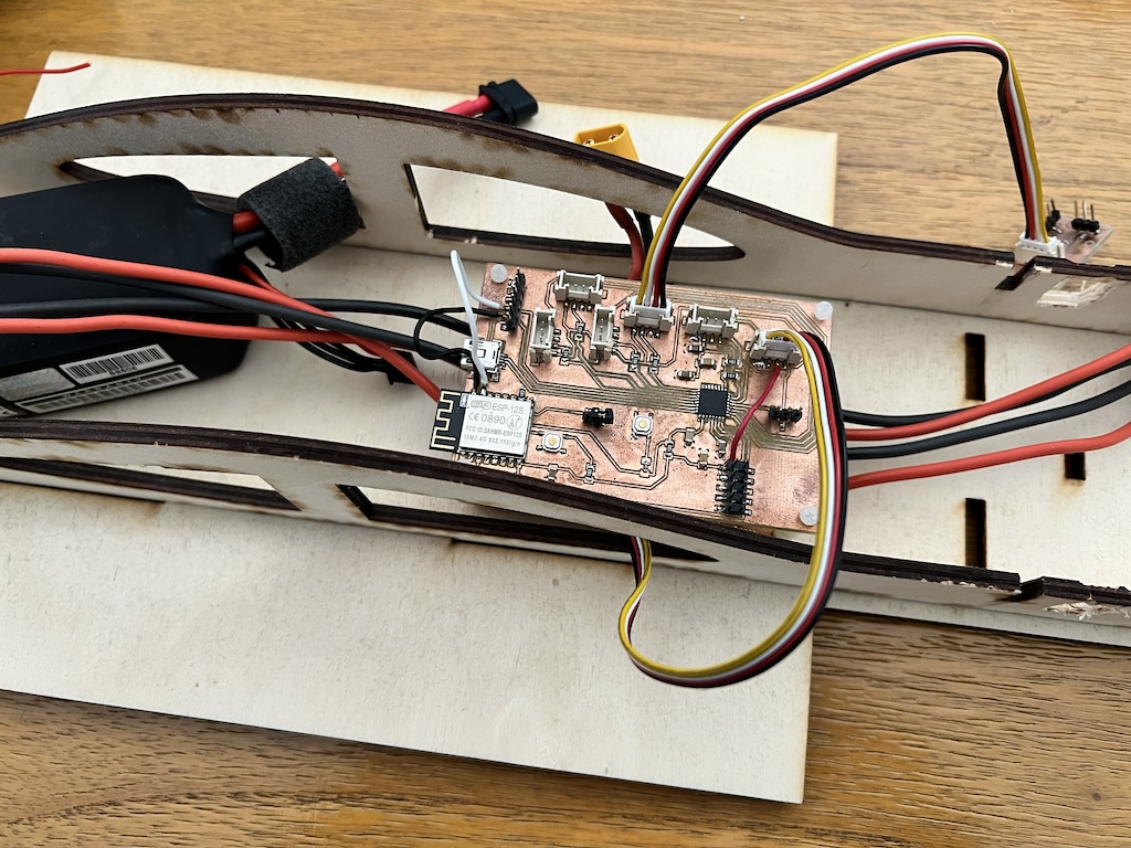
Added the power distribuition pcb.
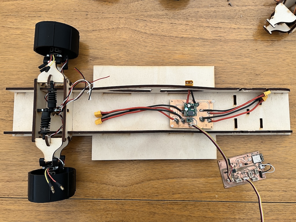
Added the controller pcb. Here it’s possible to see the “hot fixes” done in the controller board to allow proper 3.3v to reach the ESP12s and the serial connection also.
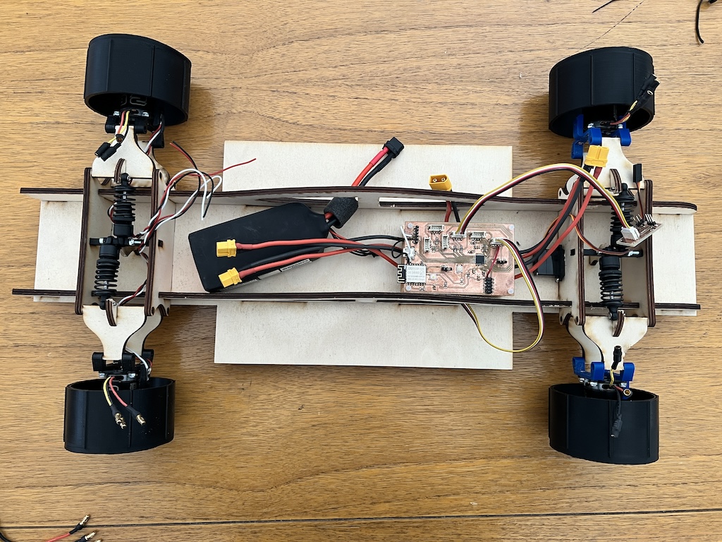
And then the front suspension with the 2 front motors.
Video
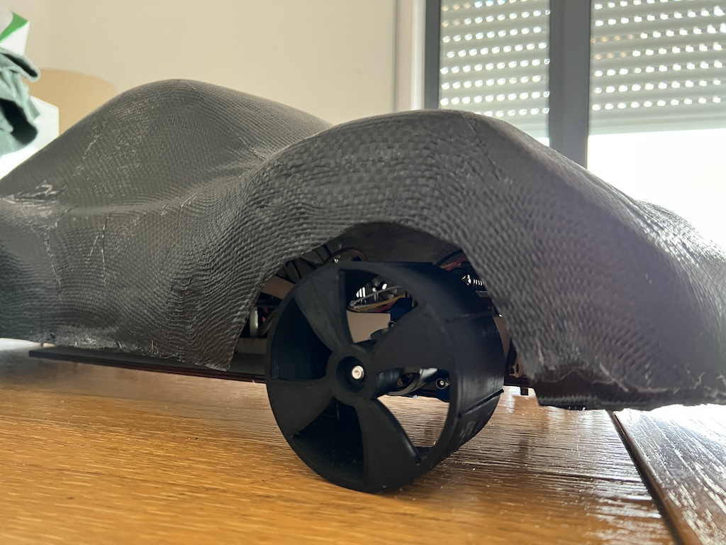
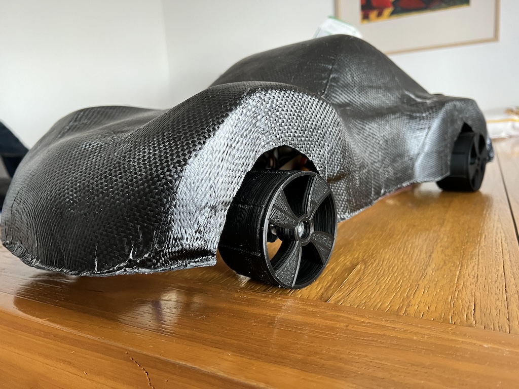
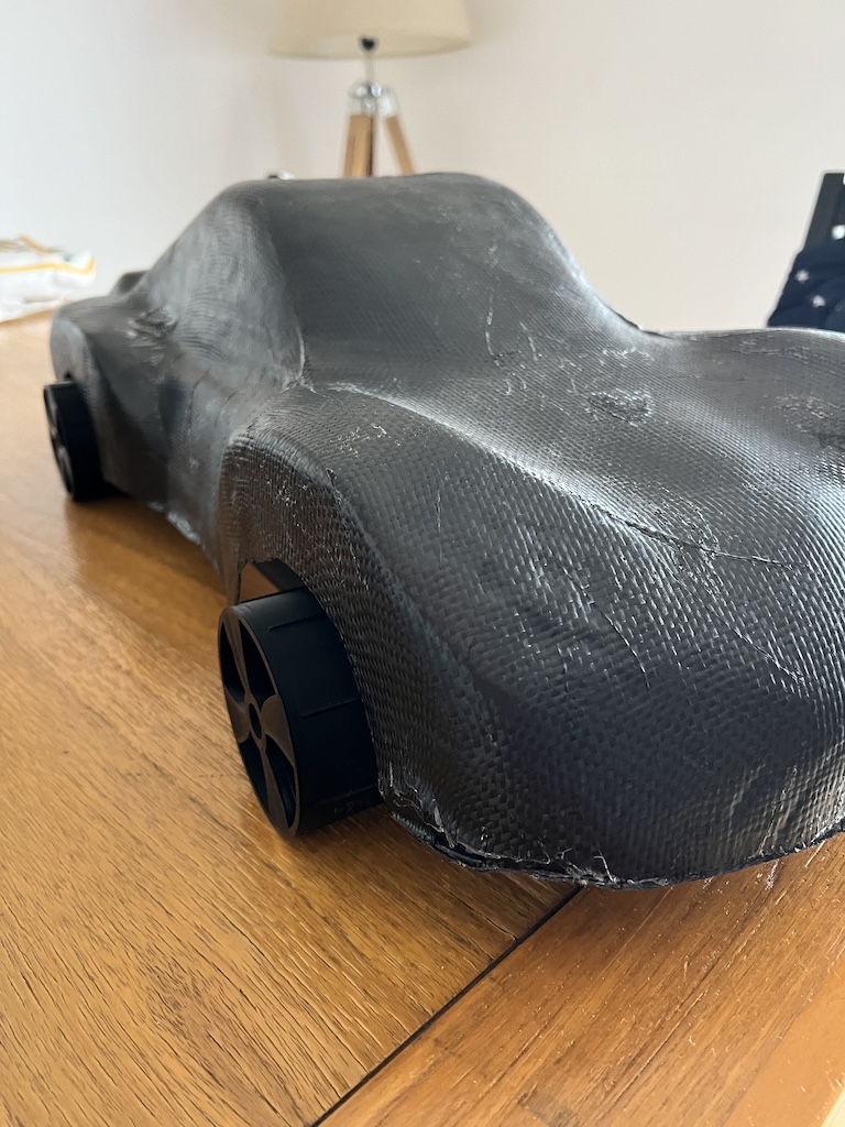
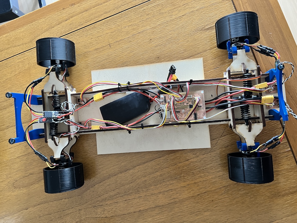
Hero shots
After Neil feedback i have improved a bit the packaging. So short wires and a bit more orgnized/clean, added front and back shell support. (Temporary glued, please don’t tell Neil :D)
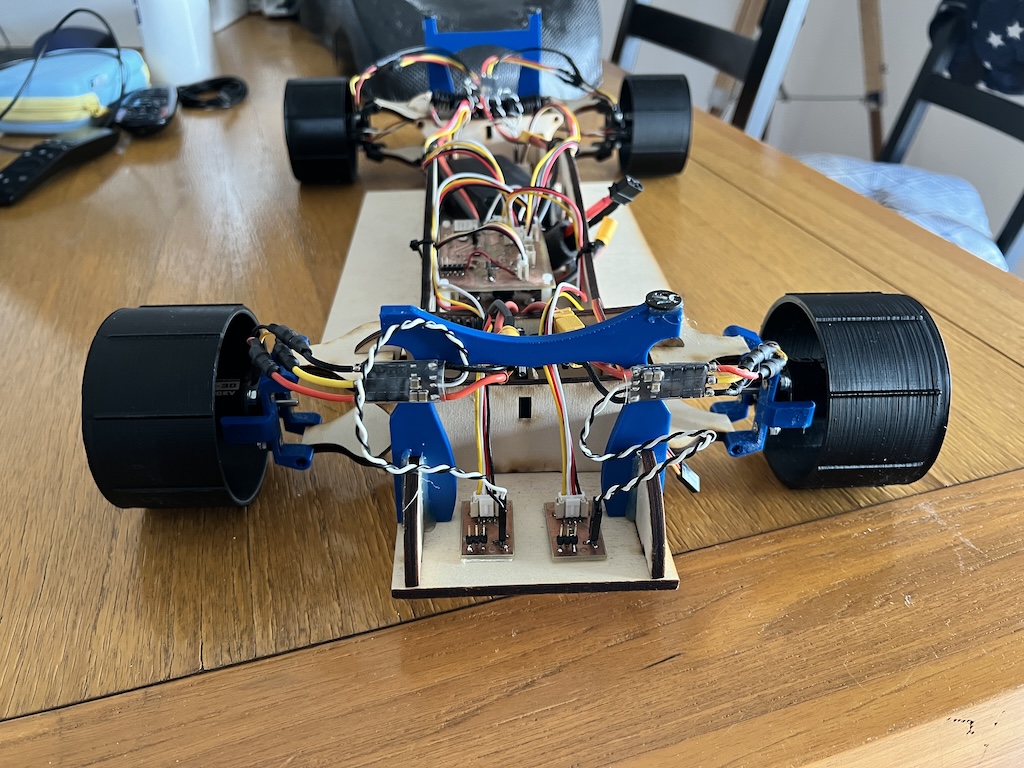
Shell is set in place by using magnets + metal washer on the top of the 3d printed supports.