12. Output devices
Learning outcomes
- Demonstrate workflows used in controlling an output device(s) with MCU board you have designed
Have you?
- Linked to the group assignment page
- Documented how you determined power consumption of an output device with your group
- Documented what you learned from interfacing output device(s) to microcontroller and controlling the device(s)
- Described your design and fabrication process or linked to previous examples.
- Explained the programming process/es you used
- Outlined problems and how you fixed them
- Included original design files and code
- Included a ‘hero shot/video’ of your board
Group assignment
- Measure the power consumption of an output device
- Document your work (in a group or individually)
For the group documentation, please check group assignment page here: Output devices (Group page)
Individual assignment
- Add an output device to a microcontroller board you’ve designed and program it to do something
For the individual assignment on Output devices i choose to use a rc grade micro servo and brushless motor as output devices to learn about Pulse-width modulation (PWM).
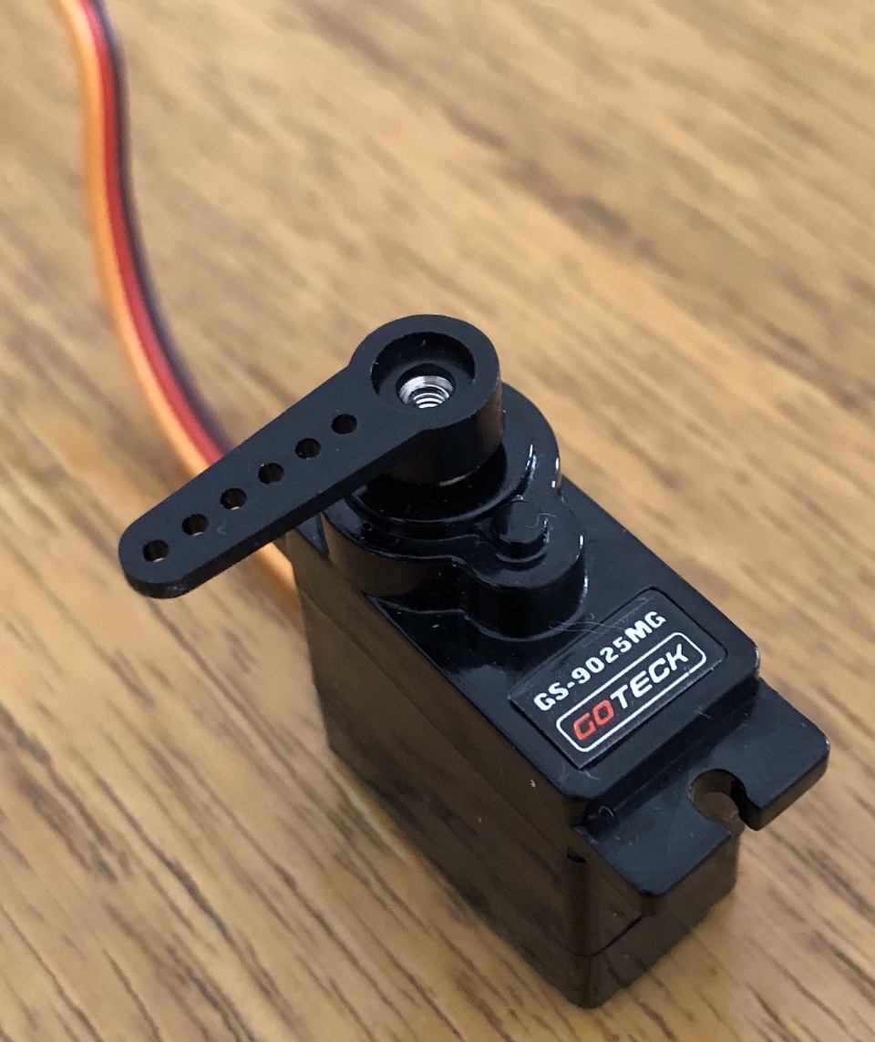
Servo datasheet: GS-9025MG.pdf
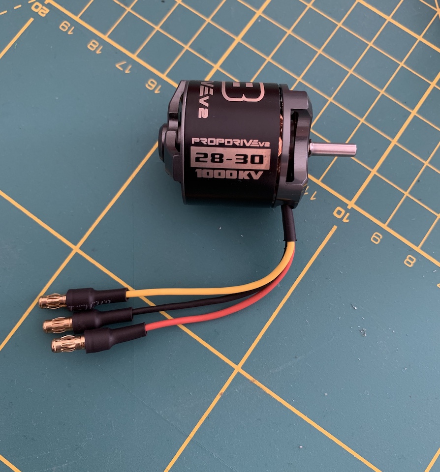
Brushless Outrunner Motor
Servo PWM (Arduino UNO)
In the beginning i used an Arduino UNO to connect and test the servo. Started by using hello.servo.44.c example and adapted it to run on the arduino.
So Arduino Uno uses an Atmega328 and for my 1st test i used digital pin 9 (PWM). From the original code i needed to change PWM_port to “PORTB” because Atmega328 doesn’t have “PORTA”, change PWM_pin to use “PB1” instead of PA1 and also PWM_direction from “DDRA” to DDRB for same reason.
Once code compiled with success have uploaded it to the Arduino and connected the servo to GND (brown cable), 5V(red cable) and signal(yellow cable) to pin 9.
The servo started to move but not as expected, the rotation wasn’t happening for all 0˚ to 180˚ range. It required some tweeking and trial of duty cycle values in ms to learn the “correct” values for 90˚ (2.475ms) and -90˚ (0.630 ms). For the 0˚ the 1.5ms worked as described in the servo datasheet.
//
// hello.servo.44.c
//
// servo motor hello-world
//
// set lfuse to 0x5E for 20 MHz xtal
//
// Neil Gershenfeld
// 4/8/12
//
// (c) Massachusetts Institute of Technology 2012
// This work may be reproduced, modified, distributed,
// performed, and displayed for any purpose. Copyright is
// retained and must be preserved. The work is provided
// as is; no warranty is provided, and users accept all
// liability.
//

#include <avr/io.h>
#include <util/delay.h>

#define output(directions,pin) (directions |= pin) // set port direction for output
#define set(port,pin) (port |= pin) // set port pin
#define clear(port,pin) (port &= (~pin)) // clear port pin
#define pin_test(pins,pin) (pins & pin) // test for port pin
#define bit_test(byte,bit) (byte & (1 << bit)) // test for bit set
#define position_delay() _delay_ms(1000)

#define PWM_port PORTB
#define PWM_pin (1 << PB1)
#define PWM_direction DDRB

int main(void) {
   //
   // main
   //
   // set clock divider to /1
   //
   CLKPR = (1 << CLKPCE);
   CLKPR = (0 << CLKPS3) | (0 << CLKPS2) | (0 << CLKPS1) | (0 << CLKPS0);
   //
   // set up timer 1
   //
   TCCR1A = (1 << COM1A1) | (0 << COM1A0); // clear OC1A on compare match
   TCCR1B = (0 << CS12) | (1 << CS11) | (0 << CS10) | (1 << WGM13); // prescaler /8, phase and frequency correct PWM, ICR1 TOP
   ICR1 = 25000; // 20 ms frequency
   //
   // set PWM pin to output
   //
   clear(PWM_port, PWM_pin);
   output(PWM_direction, PWM_pin);
   //
   // main loop
   //
   while (1) {
      //
      // 1 ms PWM on time (-90˚)
      //
      OCR1A = 630;
      position_delay();
      //
      // 1.5 ms PWM on time (0°)
      //
      OCR1A = 1500;
      position_delay();
      //
      // 2 ms PWM on time (90˚)
      //
      OCR1A = 2475;
      position_delay();
      }
   }
The servo started to move from side to side rotating right to -90˚, then left 0˚ then left again to 90˚. This can now be used to controll a rotation of the servo in a 0˚ to 180˚ range (from right to left).
Rotate servo to an angle
Now lets try to have this working in a way that instead of duty cycle values, the code specifies an angle to rotate the servo to. Something like “rotate_to(90)” and servo rotates to that position.
For convenience i define MIN_PWM value and MAX_PWM value.
#define MIN_PWM 630  // -90˚ which is the starting point of the rotation, so 0˚
#define MAX_PWM 2475 // 90˚ which is the end point of the rotation, so 180˚
And instead of passing the duty cycle value in ms i used Arduino map function to convert angle value that range from 0˚ to 180˚ into a duty cycle value in ms that ranges from MIN_PWM to MAX_PWM.
Added rotate_to function right before main function. The rotate_to function encapsulates the use of arduino map function. Receives an angle in ˚ and returns a value in ms.
int rotate_to(int angle){
  return map(angle,0,180,MIN_PWM,MAX_PWM);
}
Changed loop code using rotate_to function.
//
// main loop
//
while (1) {
   //
   // 1 ms PWM on time (-90˚)
   //
   OCR1A = rotate_to(0);
   position_delay();
   //
   // 1.5 ms PWM on time (0°)
   //
   OCR1A = rotate_to(90);
   position_delay();
   //
   // 2 ms PWM on time (90˚)
   //
   OCR1A = rotate_to(180);
   position_delay();
}
Here is a short video made to demo the servo rotation.
The full code can be downloaded here: servo.ino
Servo PWM (ATtinny44 board)
Now using my board, produced on week 11. Input devices, to controll the GS-9025MG servo. For PWM Neil’s code uses OCR1A register for PWM, which outputs in pin PA6 (one of two pins that could be used for PWM in the ATtiny44).
To have the code running on my board have just tweeked the PWM ms with same values used before and programmed the board.
Brushless motor
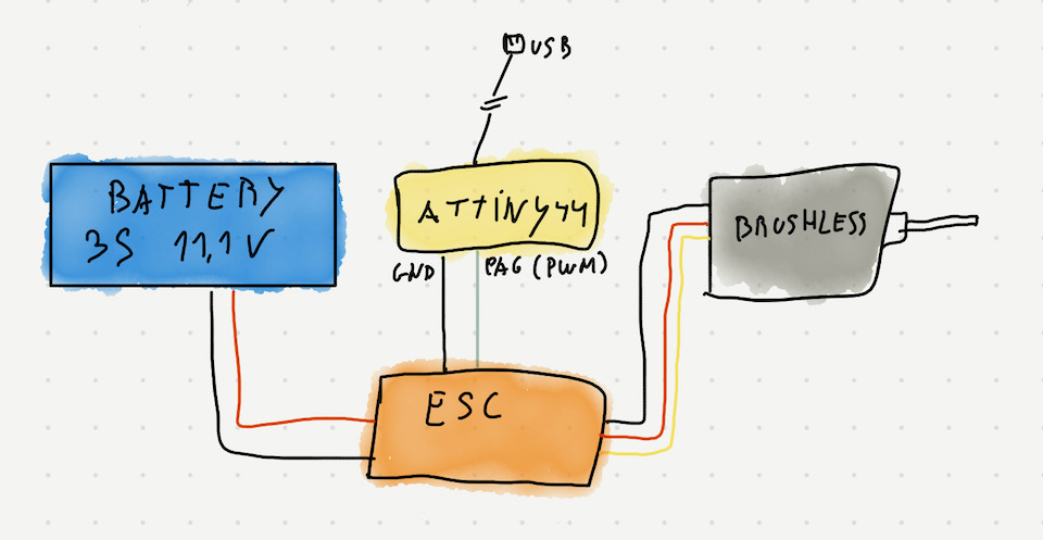
For my final project i need to controll 4 electric brushless motors. So for this week i decided also to learn how to make a brushless motor work with my ATtiny44 board (produced on week 11. Input devices). The way to make a brushless motor to work is to have a electronic speed controller(ESC) connected to the brushless motor and then use PWM to manage the ESC that in turn will manage the current from battery through the motor making it run. At this point there’s no necessity of constructing my own ESC, they are fully commoditized. Making one would only make sense at this point if i wanted to make a project around ESC development/improvement for some specific need.
The ESC used is a Turnigy MultiStar BLHELI-S 30A connected to ATtiny44 GND and PA6.
The next part was to try to make the ESC work and move the brushless motor. Usually in hobby grade ESC the PWM value is between 1000 and 2000. But this didn’t work at 1st, there is a procedure to enable the ESC to properly work (below 1200 seamed to enter programming mode). So PWM needs to be set to the lower valid PWM value, then wait for 2 seconds and after that PWM values can be set to load the motor. To discover the valid Min and Max PWM values for this ESC+Motor, i modified Neil’s code so that i could set PWM and wait for ESC to “boot” and then within a for {…} i was going to test the range of values to accelerate the motor and after to slow down and stop for some time (inside the main loop). The PWM value set was being sent via serial and read on the computer, so that i could associate the speed of the motor with the PWM value used and slowly reaching the valid interval of PWM values.
In the end, reach and defined the the final PWM values that work.
#define PWM_max 1900
#define PWM_min 1200
#define PWM_stop 1260
Main loop
// set Serial pin to output
set(serial_port, serial_pin_out);
output(serial_direction, serial_pin_out);

//
// set PWM pin to output
//
clear(PWM_port, PWM_pin);
output(PWM_direction, PWM_pin);
//
// main loop
//

OCR1A = PWM_min;
_delay_ms(ESC_boot_delay);

while (1) {

   // acceleration
   for(int x=PWM_stop; x<=1500; x+=20){
      sprintf(output, "%d\n", x);
      put_string(&serial_port, serial_pin_out, output);

      OCR1A = x;
      position_delay();
   }

   // slow down
   OCR1A = 1500;
   position_delay();

   OCR1A = 1300;
   position_delay();

   OCR1A = 1280;
   position_delay();

   // stop
   OCR1A = PWM_stop;
   position_delay();
   position_delay();

}
The result was ok, this is something i can use on my final project :)
Files: hello.servo.44.c and hello.servo.44.make.