11. Input devices
Learning outcomes
- Demonstrate workflows used in sensing something with input device(s) and MCU board
Have you?
- Linked to the group assignment page
- Documented what you learned from interfacing an input device(s) to microcontroller and how the physical property relates to the measured results
- Documented your design and fabrication process or linked to previous examples.
- Explained the programming process/es you used
- Explained problems and how you fixed them
- Included original design files and source code
- Included a ‘hero shot/video’ of your board
Group assignment
- Probe an input device(s)’s analog and digital signals
- Document your work (in a group or individually)
For the group documentation, please check group assignment page here: Input devices (Group page)
Individual assignment
Distance HC-SR04 (sonar)
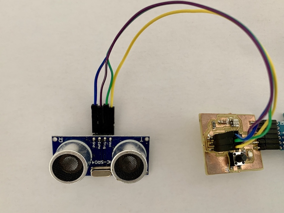
For this week assignment i started by using my board (built in 7. Electronics design and programmed in week 9. Embedded programming) to try to read the distance sensor HC-SR04 (Sonar), like the one Neil’s talked in the class hello.HC-SR04. This sensor is an active sonar and works by emiting sound (40 kHz) and listening for its reflection in an object. This allows to calculate, based on speed of sound in air, the distance to an object.
| HC-SR04 Specifications | |
|---|---|
| Working Voltage | DC 5 V |
| Working Current | 15mA |
| Working Frequency | 40Hz |
| Max Range | 4m |
| Min Range | 2cm |
| MeasuringAngle | 15 degree |
| Trigger Input Signal | 10uS TTL pulse |
| Echo Output Signal Input | TTL lever signal and the range in proportion |
| Dimension | 45 * 20 * 15mm |
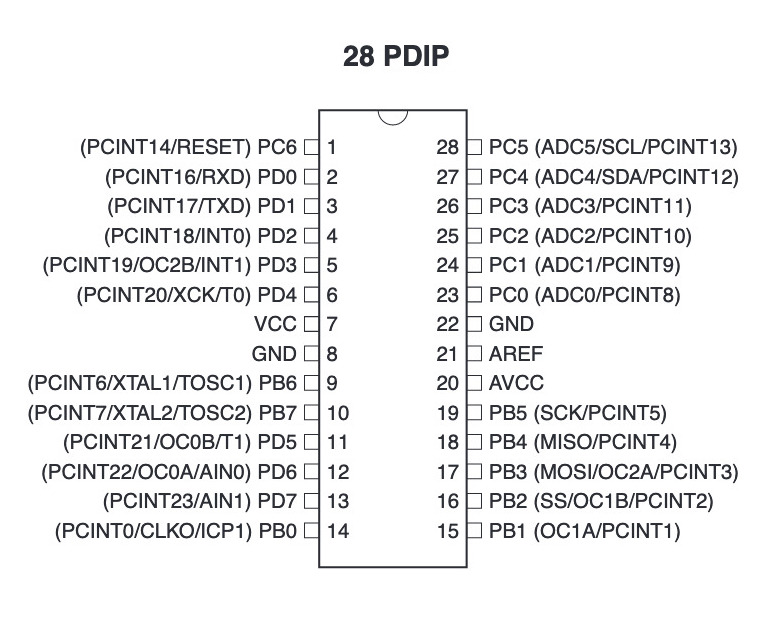
Based on Neil’s example have updated the code for my board. The SR04 echo pin was connected in PA5 and trigger pin on PA6.
(...)

#define serial_port PORTA
#define serial_direction DDRA
#define serial_pin_out (1 << PA1)
#define trigger_port PORTA
#define trigger_direction DDRA
#define trigger_pin (1 << PA6)
#define echo_pins PINA
#define echo_direction DDRA
#define echo_pin (1 << PA5)

(...)
File: hello.HC-SR04.c
And respective make file update for attiny44.
File: hello.HC-SR04.make
To program the board is same command as before:
make -f hello.HC-SR04.make program-usbtiny
The for the interface adjusted the the counter for my board on Neil’s hello.HC-SR04.py code.
(...)

us = filt/20.0 # 20 MHz counter

(...)
File: hello.HC-SR04.py
After making the sensor connections, started the interface:
python hello.HC-SR04.py /dev/cu.usbmodem141401
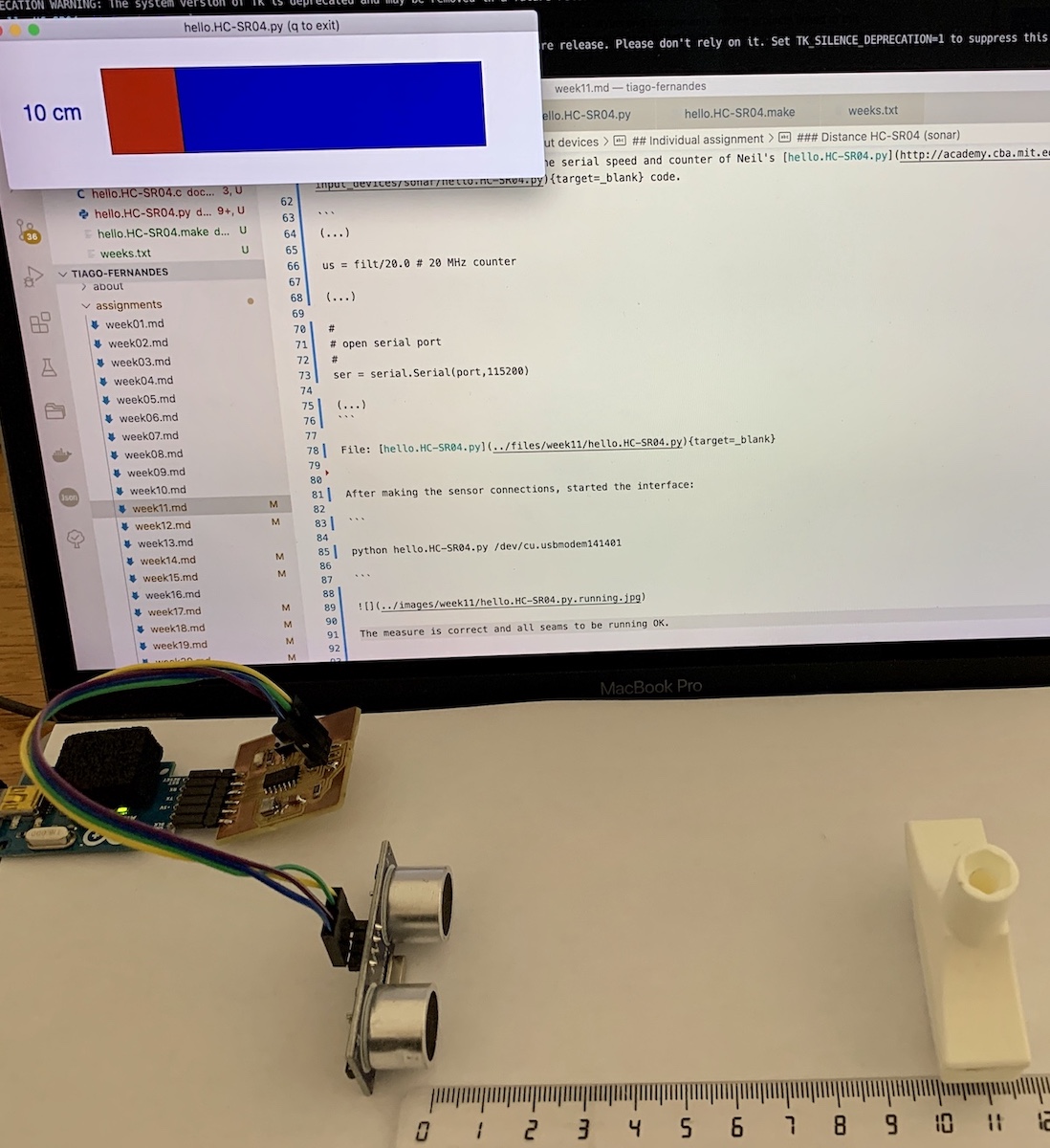
The measure is correct and all seams to be running OK but this didn’t work well on first try. Values weren’t correct until i notice that i would need to adjust python code because my board uses a 20Mhz resonator :)
Links
VL53L0X Time-of-Flight
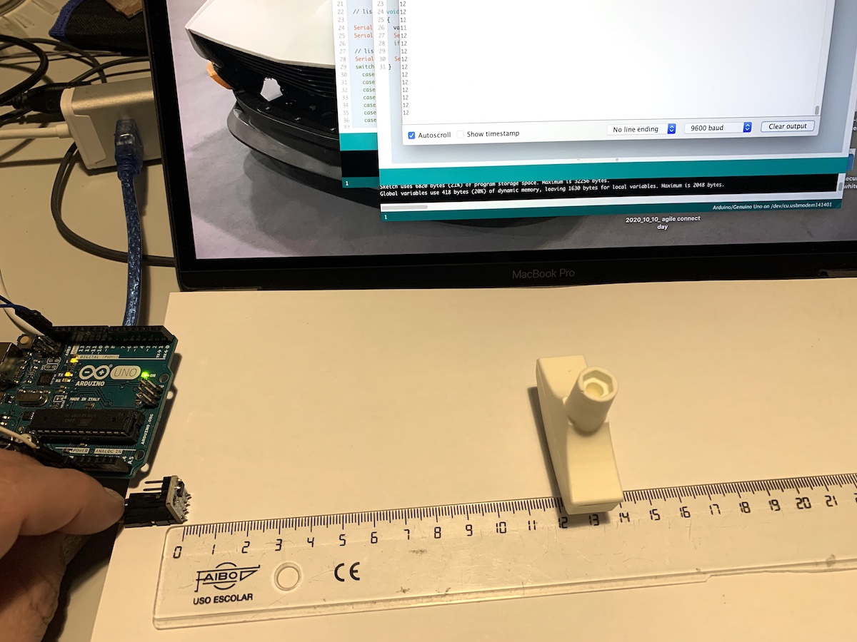
Used an Arduino Uno board to try to read from VL53L0X Time-of-Flight sensor. This will allow to learn about the sensor, test it and then eventually try to make same readings using any of my boards.
Note
For the final project i plan to use the Time-of-Flight and accelerometer sensors, so this is also part of exploratory work done for the final project.
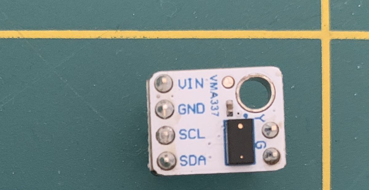
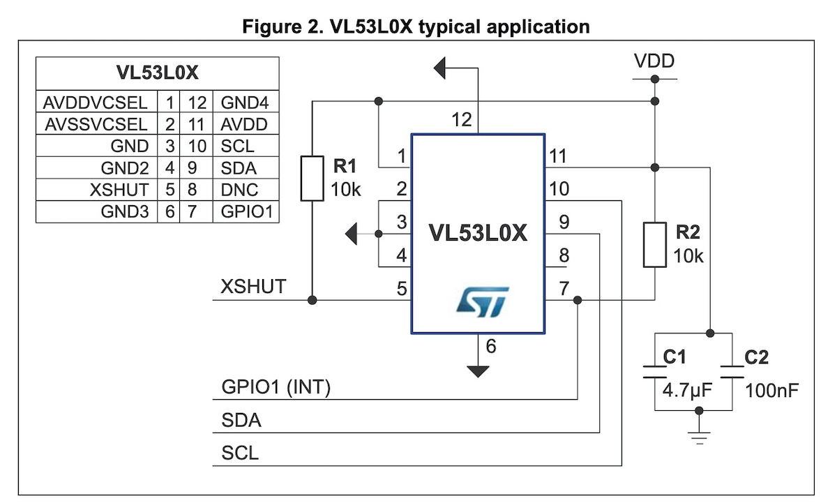
These PCB includes the sensors and they have already the pull-up resistor for SDA and SCL to have I2C working.
| VL53L0X specification | |
|---|---|
| power supply | 3.3 - 5 VDC |
| infrared emitter | 940 nm |
| measuring range | 30 to 2000 mm |
| ranging accuracy | +/- 3 % |
| sampling time | <= 30 ms |
| operating temperature | -20 to 70 °C |
| interface type | I2C |
| supply current | 10 mA |
| XSHUT and GDPIO voltage | max 2.8 V |
For a 1st step i tested the sensor with an Arduino Uno board with Popolu VL53L0X arduino library. Downloaded the library and added it into my “Arduino/libraries” directory.
The connection between the Arduino board (ATmega328) and VL53L0X sensor is done using the I2C protocol.
Connected the sensor to Arduino I2C pins (SDA, SCL GND and VCC) and used this example code from the library to get a continuous distance reading in cm.
#include <Wire.h>
#include <VL53L0X.h>

VL53L0X sensor;

void setup()
{
  Serial.begin(9600);
  Wire.begin();

  sensor.init();
  sensor.setTimeout(500);

  // Start continuous back-to-back mode (take readings as
  // fast as possible).  To use continuous timed mode
  // instead, provide a desired inter-measurement period in
  // ms (e.g. sensor.startContinuous(100)).
  sensor.startContinuous();
}

int value=0;

void loop()
{
  value = sensor.readRangeContinuousMillimeters();
  Serial.print(value/10);
  if (sensor.timeoutOccurred()) { Serial.print(" TIMEOUT"); }

  Serial.println();
}
The sensor started to continuously output the distance between sensor and object in front. The reading looks correct, 12cm.
Links
LIS3DH 3-Axis accelerometer
Now for the accelerometer sensor, also testing it on Arduino Uno board 1st.
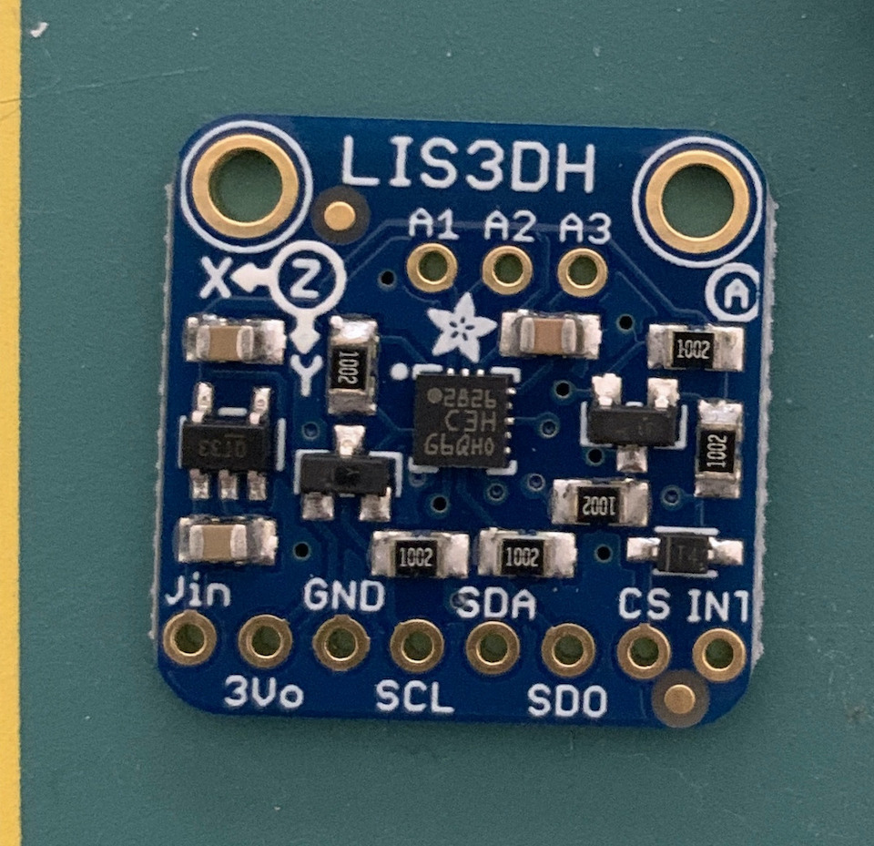

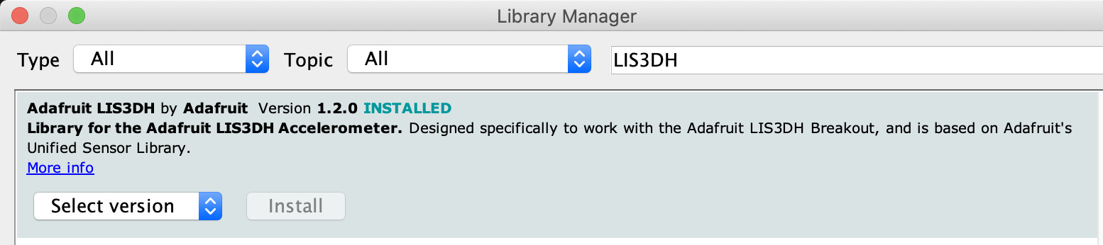
Installed in Arduino IDE the LIS3DH Arduino Library from “Tools -> Manage libraries…”.
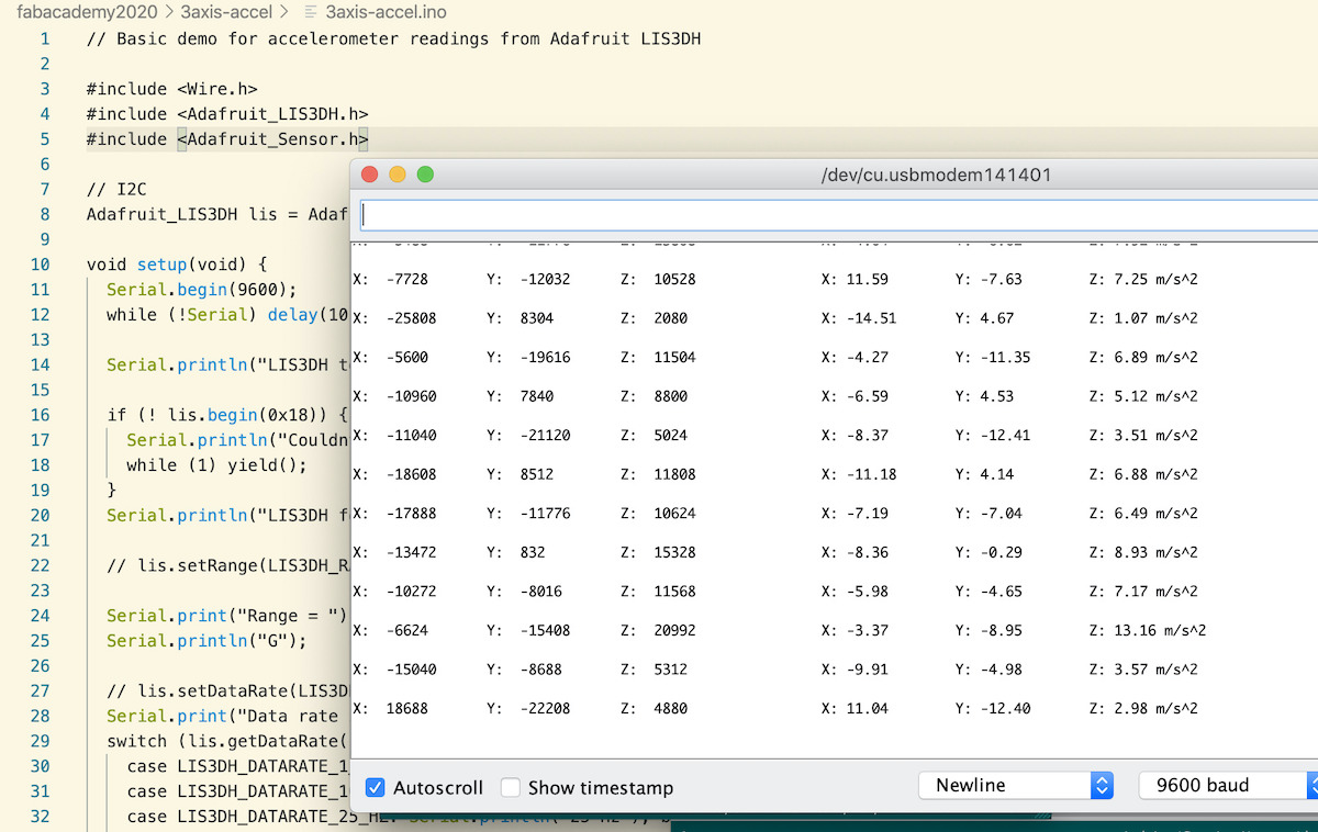
And used the acceldemo code in library examples and changed it to read values from the accelerometer by using I2C protocol.
// Basic demo for accelerometer readings from Adafruit LIS3DH

#include <Wire.h>
#include <Adafruit_LIS3DH.h>
#include <Adafruit_Sensor.h>

// I2C
Adafruit_LIS3DH lis = Adafruit_LIS3DH();

void setup(void) {
  Serial.begin(9600);
  while (!Serial) delay(10);     // will pause Zero, Leonardo, etc until serial console opens

  Serial.println("LIS3DH test!");

  if (! lis.begin(0x18)) {   // change this to 0x19 for alternative i2c address
    Serial.println("Couldnt start");
    while (1) yield();
  }
  Serial.println("LIS3DH found!");

  // lis.setRange(LIS3DH_RANGE_4_G);   // 2, 4, 8 or 16 G!

  Serial.print("Range = "); Serial.print(2 << lis.getRange());
  Serial.println("G");

  // lis.setDataRate(LIS3DH_DATARATE_50_HZ);
  Serial.print("Data rate set to: ");
  switch (lis.getDataRate()) {
    case LIS3DH_DATARATE_1_HZ: Serial.println("1 Hz"); break;
    case LIS3DH_DATARATE_10_HZ: Serial.println("10 Hz"); break;
    case LIS3DH_DATARATE_25_HZ: Serial.println("25 Hz"); break;
    case LIS3DH_DATARATE_50_HZ: Serial.println("50 Hz"); break;
    case LIS3DH_DATARATE_100_HZ: Serial.println("100 Hz"); break;
    case LIS3DH_DATARATE_200_HZ: Serial.println("200 Hz"); break;
    case LIS3DH_DATARATE_400_HZ: Serial.println("400 Hz"); break;

    case LIS3DH_DATARATE_POWERDOWN: Serial.println("Powered Down"); break;
    case LIS3DH_DATARATE_LOWPOWER_5KHZ: Serial.println("5 Khz Low Power"); break;
    case LIS3DH_DATARATE_LOWPOWER_1K6HZ: Serial.println("16 Khz Low Power"); break;
  }
}

void loop() {
  lis.read();      // get X Y and Z data at once
  // Then print out the raw data
  Serial.print("X:  "); Serial.print(lis.x);
  Serial.print("  \tY:  "); Serial.print(lis.y);
  Serial.print("  \tZ:  "); Serial.print(lis.z);

  /* Or....get a new sensor event, normalized */
  sensors_event_t event;
  lis.getEvent(&event);

  /* Display the results (acceleration is measured in m/s^2) */
  Serial.print("\t\tX: "); Serial.print(event.acceleration.x);
  Serial.print(" \tY: "); Serial.print(event.acceleration.y);
  Serial.print(" \tZ: "); Serial.print(event.acceleration.z);
  Serial.println(" m/s^2 ");

  Serial.println();

  delay(200);
}
Managed to read the X,Y and Z values of the accelerometer, so sensor test OK.
Now without using Arduino platform, based on Neil hello.ADXL343.c example and using my ATtiny44 board.
So have updated the serial config, the i2c slave address, SCL and SDA pins to use by attiny44 board (same used below in step sensor). At this point and after digging in the LIS3DH datasheet, defined also some macros to help to make the code more readable (CTRL_REG1, CTRL_REG4 and respective bits). The OUT_X_L 0x28 is the where the sensor starts to save data as two’s complement left-justified, up to OUT_X_H 0x2D (6 bytes starting from 0x28).
#define serial_port PORTA
#define serial_direction DDRA
#define serial_pin_out (1 << PA1)

#define I2C_slave_address 0x18 // LIS3DH alt address
#define I2C_delay() _delay_us(6)
#define SCL_pin (1 << PA5)
#define SCL_pins PINA
#define SCL_port PORTA
#define SCL_direction DDRA
#define SDA_pin (1 << PA3)
#define SDA_pins PINA
#define SDA_port PORTA
#define SDA_direction DDRA

// LIS3DH registers
#define CTRL_REG1 0x20
#define ODR3 7
#define ODR2 6
#define ODR1 5
#define ODR0 4
#define LPEN 3
#define Zen 2
#define Yen 1
#define Xen 0

#define CTRL_REG4 0x23
#define BDU 7
#define BLE 6
#define FS1 5
#define FS0 4
#define HR 3
#define ST1 2
#define ST0 1
#define SIM 0

#define STATUS_REG_AUX 0x07
#define OUT_X_L 0x28
Before the main loop, did the sensor initialization after I2C_init(). It’s required to do the init of the sensor to remove it from power-down mode, enable X, Y, Z axis and have it writing the X, Y and Z registers data in a expected format.
So in CTRL_REG1 Zen, Yen and Zen bits are set to 1 to enable all 3 axis. LPen and HR (in CTRL_REG4) are set to 0 for normal mode and low-resolution, 10 bit axis data).
The ODR bits were used to set data rate to 400Hz.
   // LIS3DH boot
   _delay_us(5);

   I2C_init();

   unsigned char ctrl_reg1_config = (0 << ODR3) | (1 << ODR2) | (1 << ODR1) | (1 << ODR0) | (0 << LPEN) |
                                    (1 << Zen) | (1 << Yen) | (1 << Xen);

   data[0] = CTRL_REG1; // register
   data[1] = ctrl_reg1_config;
   ret = I2C_master_write(data, 2, I2C_slave_address);

   _delay_us(5);

   unsigned char ctrl_reg4_config =  (0 << BDU) | (0 << BLE) | (0 << FS1)| (0 << FS0) | (0 << HR) |
                                     (0 << ST1) | (0 << ST0) | (0 << SIM);

   data[0] = CTRL_REG4; // register
   data[1] = ctrl_reg4_config;
   ret = I2C_master_write(data, 2, I2C_slave_address);

   _delay_us(5);

   data[0] = 0x0F; // device ID register
   ret = I2C_master_write(data,1,I2C_slave_address);
   ret = I2C_master_read(data,1,I2C_slave_address);

   if(data[0] == 0x33){
      put_string(&serial_port, serial_pin_out, "LIS3DH detected...");
   }
Then in the main loop if there is new data set in the registers, then reads them from the sensor and send them via serial. The OUT_X_L | 0x80 allows to set the 7 bit of the address to 1. This is important because it’s how the sensor knows that the program is going to make multiple byte readings (6 bytes in this case).
//
      // main loop
      //

      // read the status register
      data[0] = STATUS_REG_AUX;
      ret = I2C_master_write(data,1,I2C_slave_address);
      ret = I2C_master_read(data,1,I2C_slave_address);

      // check for new data set
      if((data[0] & 0b10001000) == 0b10001000){

         // read data
         data[0] = OUT_X_L | 0x80; // enable multiple bytes read;
         ret = I2C_master_write(data,1,I2C_slave_address);
         ret = I2C_master_read(data,6,I2C_slave_address);

         //
         // send framing
         //
         put_char(&serial_port,serial_pin_out,1);
         put_char(&serial_port,serial_pin_out,2);
         put_char(&serial_port,serial_pin_out,3);
         put_char(&serial_port,serial_pin_out,4);

         // send data
         //
         put_char(&serial_port,serial_pin_out,data[0]);
         put_char(&serial_port,serial_pin_out,data[1]);
         put_char(&serial_port,serial_pin_out,data[2]);
         put_char(&serial_port,serial_pin_out,data[3]);
         put_char(&serial_port,serial_pin_out,data[4]);
         put_char(&serial_port,serial_pin_out,data[5]);

         _delay_us(30000);
      }
After a lot of trial and error and going through the datasheet to understand how to configure the sensor and make readings, it finally works, you can see X and Y axis being tested.
Files: hello.LIS3DH.44.c, hello.LIS3DH.44.c.make and the python interface.
Links
Step response sensor (transmit-receive)
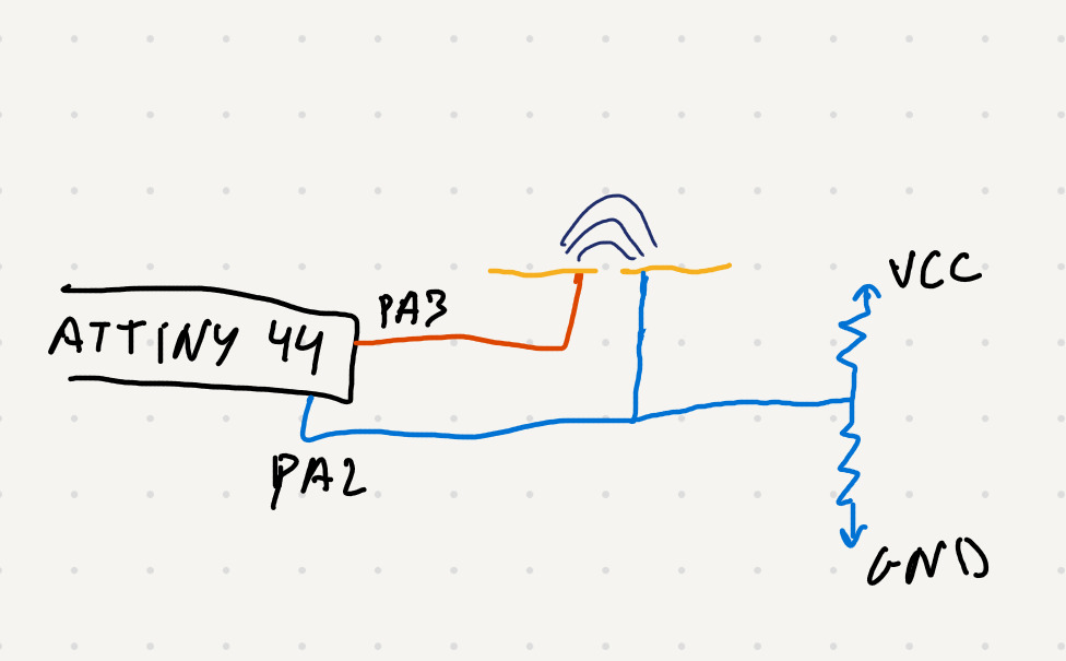
From the sensors presented by Neil on this week class i decided to create a board for step response sensor (Transmit-Receive) and try to detect when something moves close to the plates.
So this means that i need to have a TX (PA3) and RX (PA2) pin on my board so that i can read values during time as it charge/discharge and calculate the difference between readings to detect if there is something interacting with the electric field between 2 electrodes.
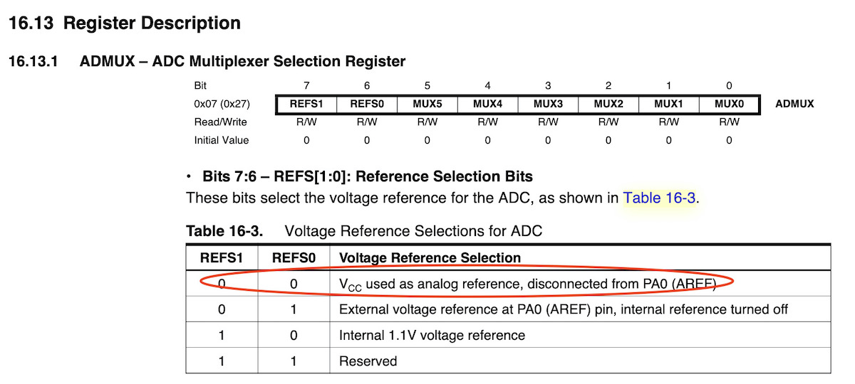
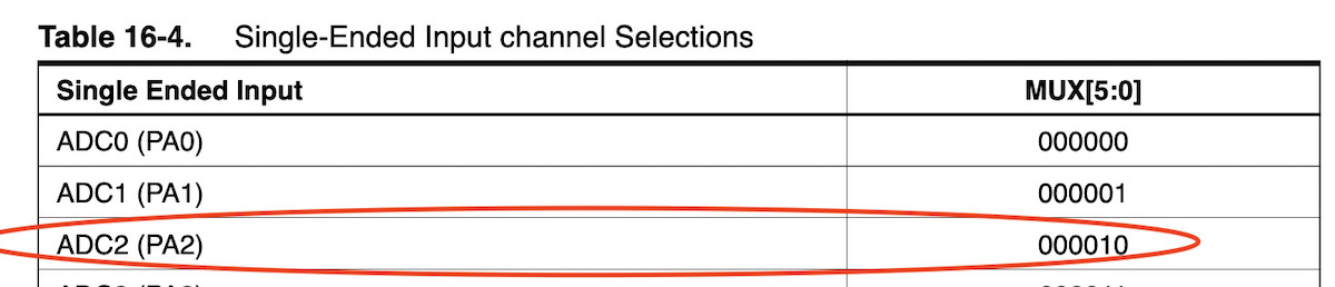
Ok, bit how is the reading really done ? It’s done by using the Analog to Digital Converter (ADC) in the ATTiny44. To use this i went to the ATtiny44A Complete datasheet page 132 and read from there, about the ADC. How ADC is enabled by setting the ADC Enable bit (ADEN) in ADC Control and Status Register A (ADCSRA), how to operate it, start a convertion of the analog value into 10bit (digital) value and why we need to configure a prescalar to keep the ADC input clock between 50kHz to 200kHz. Needed to do this also to understand a bit better Neil’s code, so now i understand also how to select board Vcc as reference and select the single-ended input pin via ADC Multiplexer select (ADMUX) registers. ADC diagram is in Figure 16-1.
For the new board:
| Components | Quantity |
|---|---|
| ATtiny44A-SU | 1 |
| ECS-CR2-20.00-B-TR (20Mhz Resonator) | 1 |
| R 10K ohm SMD 1206 | 1 |
| R 1M ohm SMD 1206 | 2 |
| Capacitor 1uF SMD | 1 |
| Headers 2x3 | 1 |
| Headers 2x2 | 1 |
| FTDI header | 1 |
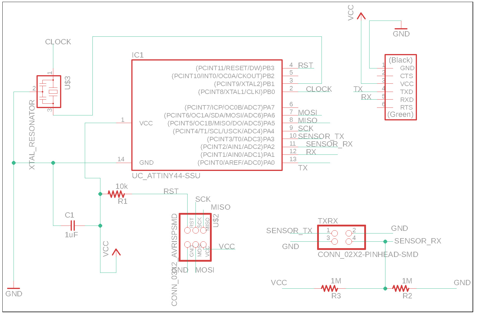
Started by creating creating a new project in Eagle, based on my weeek 7. Electronics design and followed same steps to create a new board for step response sensor.
Schema design.
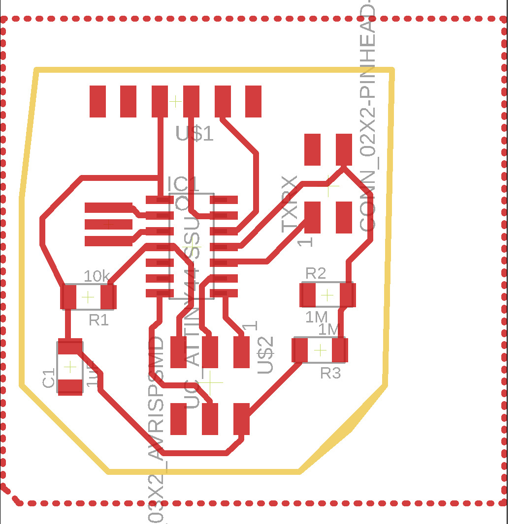
Board with GND layer.
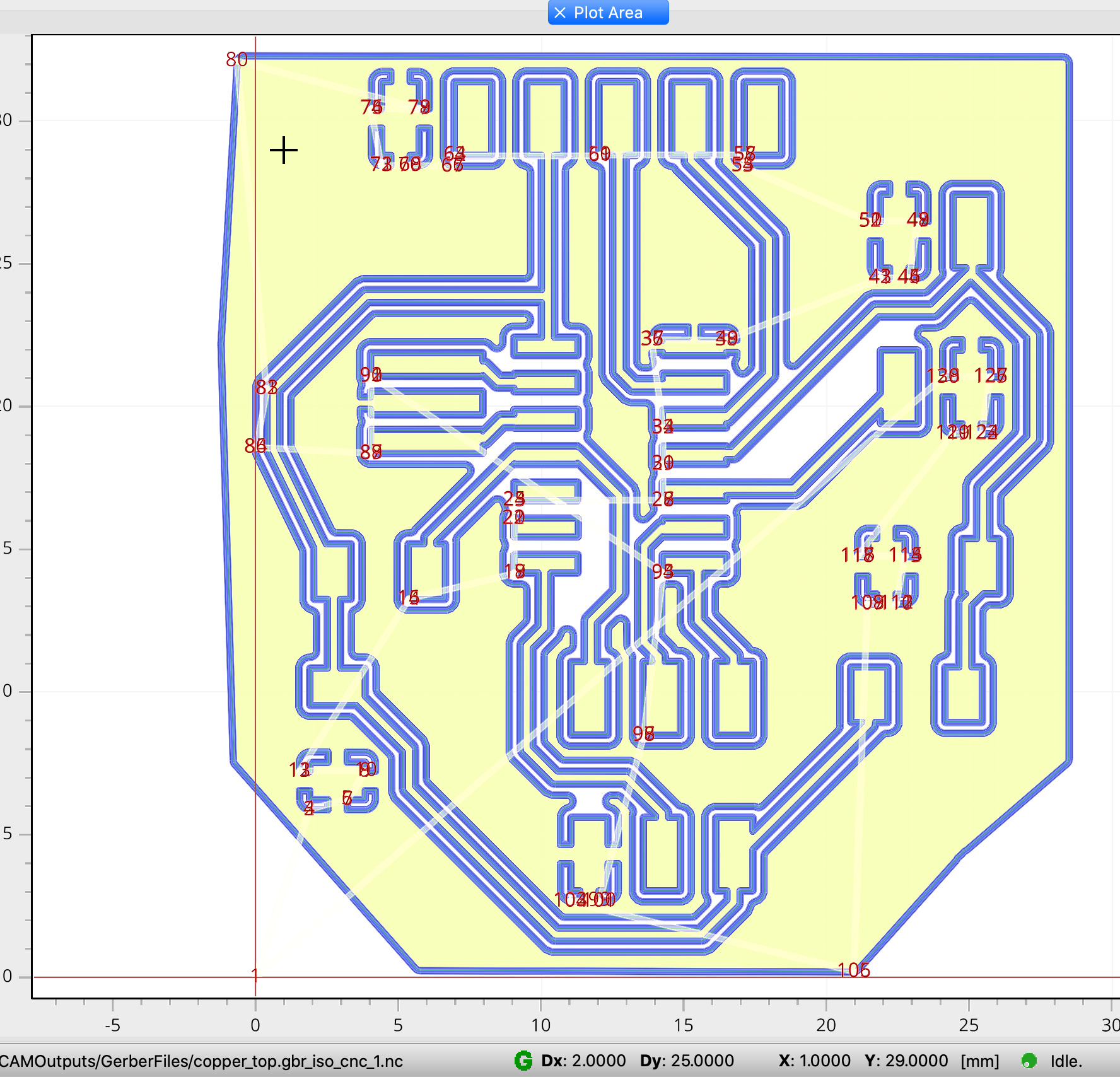
FlatCAM path isolation.
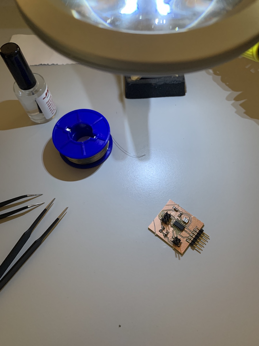
The milled board after getting out of the cnc.
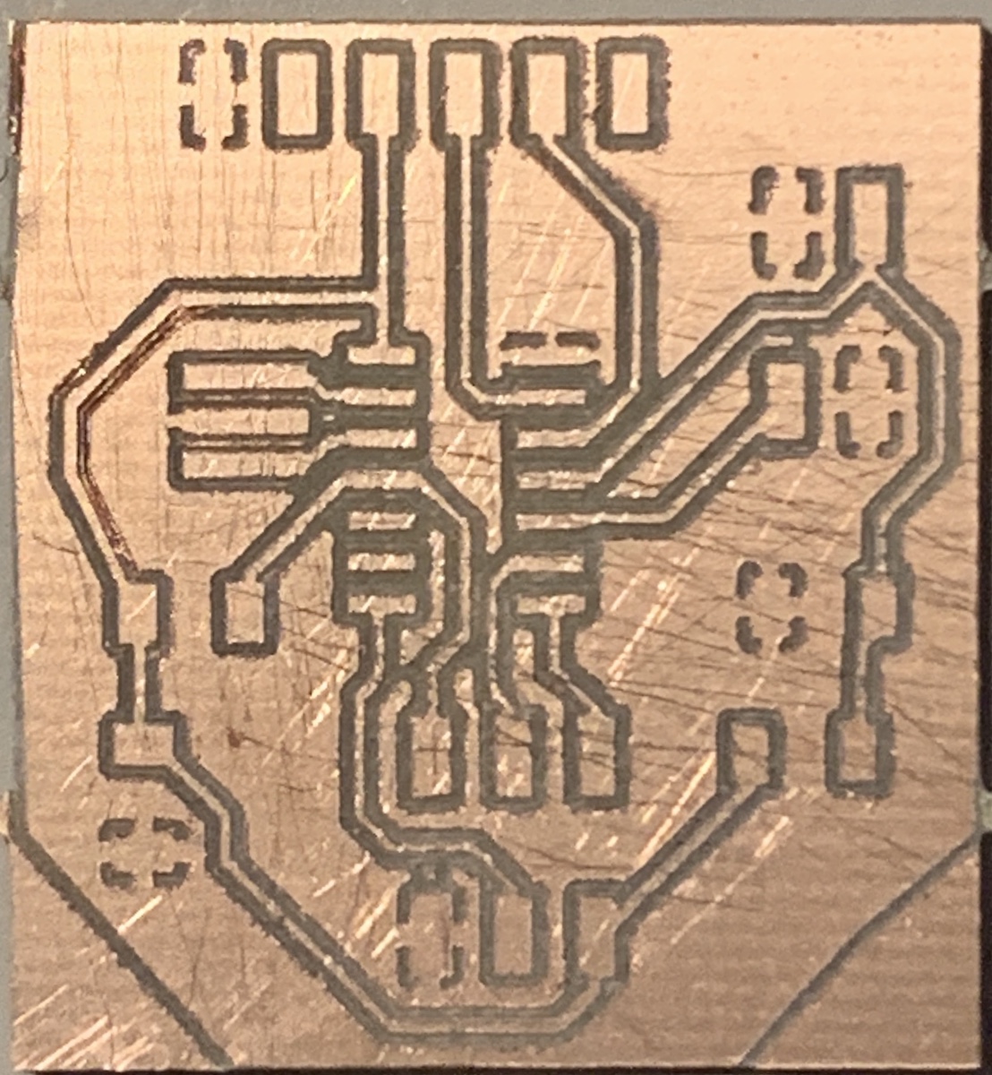
After some cleaning to have path complete isolated i stuffed the board. Add a little issue with the resistor, didn’t have 1M ohm around and i needed 2. So used 300k and 680k registors in serial make a 980k ohm resistor (~ 1M ohm). Later will replace the resistors by the 1M ohm as it should.
The program i used was Neil’s example hello.txrx.45.c, hello.txrx.45.make and python interface hello.txrx.45.py. Made small changes to the C and Make files so that i could work with my board.
#define serial_port PORTA
#define serial_direction DDRA
#define serial_pin_out (1 << PA1)
#define transmit_port PORTA
#define transmit_direction DDRA
#define transmit_pin (1 << PA3)
and updated the ADMUX initialization also to work with ATTiny44.
//
// init A/D
//
ADMUX = (0 << REFS1) | (0 << REFS0) // Vcc ref
   | (0 << ADLAR) // right adjust
   | (0 << MUX5) | (0 << MUX4 )| (0 << MUX3) | (0 << MUX2) | (1 << MUX1) | (0 << MUX0); // PA2
ADCSRA = (1 << ADEN) // enable
   | (1 << ADPS2) | (1 << ADPS1) | (1 << ADPS0); // prescaler /128
The hello.txrx.44.make was made based on 5. Electronics production week, i’m using ATtiny44 and Neil’s using ATTiny45.
Files:
So after compiling and programming the board was time to test it. Connected the sensor transmit and receive pin on two separated (used pcb) plates and added a paper sheet on top to isolade the plates from my hand.
It worked :) as you can see in the video the hand is detected by the electric field between the two plates, so this value could be used to trigger any event.