10. Molding and casting
Learning outcomes
- Design appropriate objects within the limitations of 3 axis machining
- Demonstrate workflows used in mould design, construction and casting
Have you?
- Linked to the group assignment page
- Reviewed the safety data sheets for each of your molding and casting materials
- Made and compared test casts with each of them
- Documented how you designed your 3D mould and created your rough and finish toolpaths for machining, including machine settings
- Shown how you made your mould and cast the parts
- Described problems and how you fixed them
- Included your design files and ‘hero shot’ of the mould and the final object
Group assignment
- Review the safety data sheets for each of your molding and casting materials
- Make and compare test casts with each of them
For the group documentation, please check group assignment page here: Molding and Casting (Group page)
Individual assignment
For this week assignment choose to design a small tool, a T-shape socket wrench, that could be used to tighten the wheel lock nut (standard M5 nut) of my project.
Object design and tools
Started by designing the object that will serve as positive to create the mold.
This design for 3D printing should work ok, but to be used to create a mold using wax, it’s not so direct/easy. The object is “simple” but needs to be designed around the wax and tools used to mill the wax.
So the tools to use were:
| Flat Head End Mill | Lollipop End Mill | |
|---|---|---|
| Diameter | 2mm | 2mm |
| Shaft Diameter | 2.3mm | 2.3mm |
| Overall length | 44.5mm | 44.5mm |
| Length bellow holder | 32mm | 32mm |
| Shoulder length | 10mm | 10mm |
| Flute length | 5.3mm | 2mm |
| Number of flutes | 8 | 8 |
The Flat Head End Mill is going to be used to make the first rough cut in the wax. The next milling steps are 2 passes to reduce surface roughness and will be done with the Lollipop End Mill. This should allow the last pass to make the wrench surfaces smooth.
The wax used was in the form a rectangular block of size: 165mm x 80mm x 37mm.
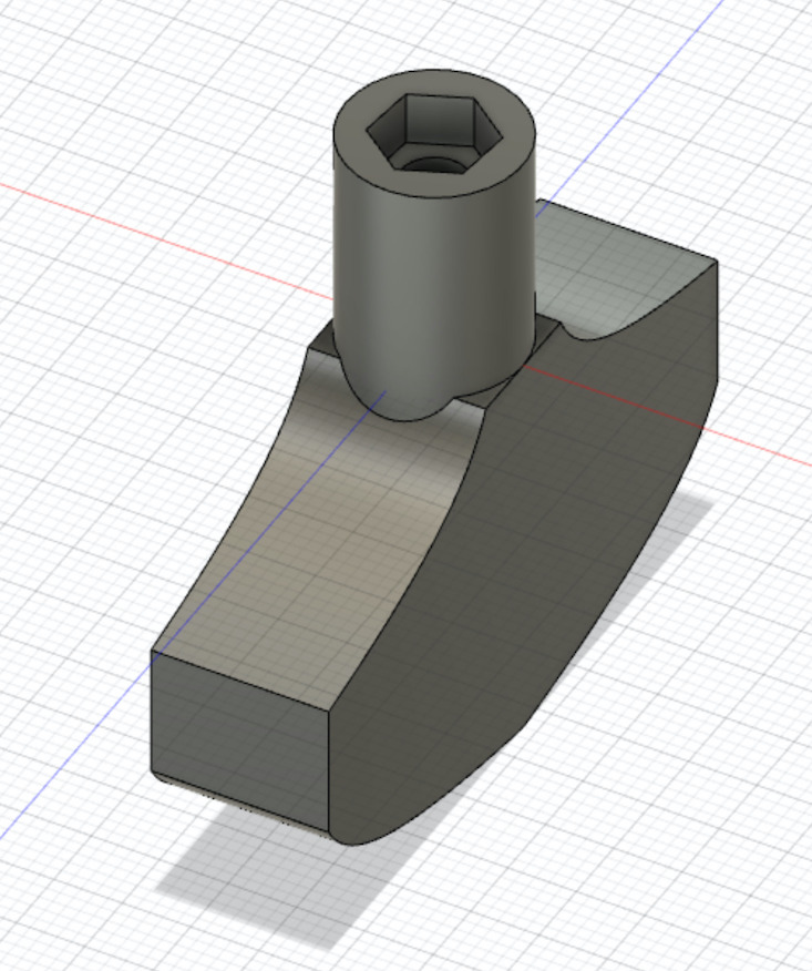
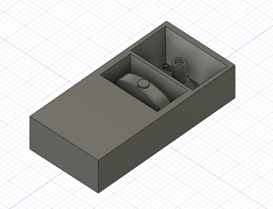
For this object in the top there’s a hole in the form of an hexagon, to hold the nut and rotate in the screw. This means that when making the mold, silicone will need to enter this hole. The height of the wrench if bigger than the wax height (37mm) and End Mills length. So The object needs to be splitted into 2, having a bottom and top molds. This means creating/milling 2 pockets in the wax.
Other design features like vertical walls higher than End Mill shoulder length, aren’t good because the shaft diameter is slightly bigger than the diameter of the tool. So vertical walls were adjusted to have 10° angle, which allows the end mills to reach and mill wax properly in the 3-axis milling process.
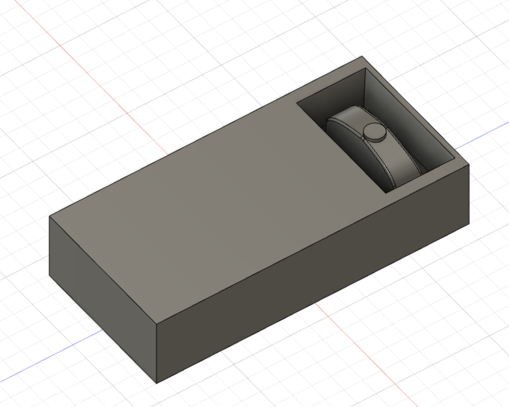
Several iterations in the design were made and the last one is displayed below. The wrench is splied in top part with ~29mm and bottom with ~20mm (bellow the wax height). The cilinder in the top part was adjusted to have a small diameter in the top and large in the base. The walls have ~10° inclination. For the base the same angle was used, but inverted. This is because the bottom of the base is milled from bottom of the base, up (into the plan split).
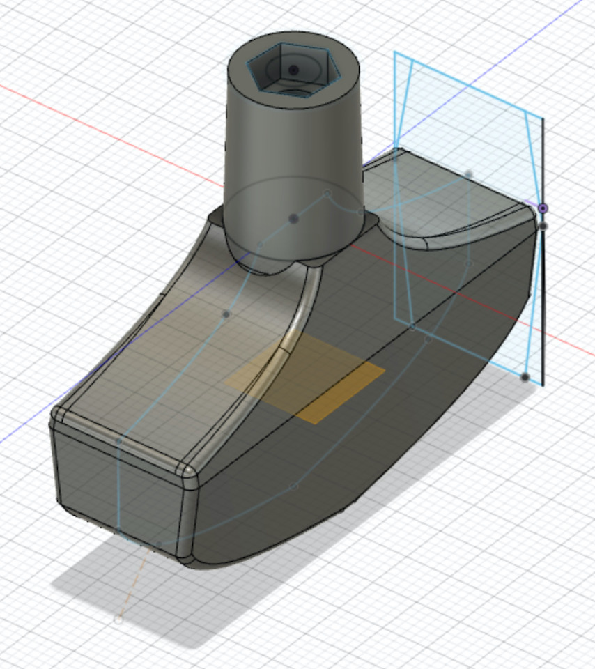
File: Fusion 360 T-Socket wrench
Mold design
Created a new project in Fusion 360 to setup the design that would be milled to then pour the silicone and make the molds.
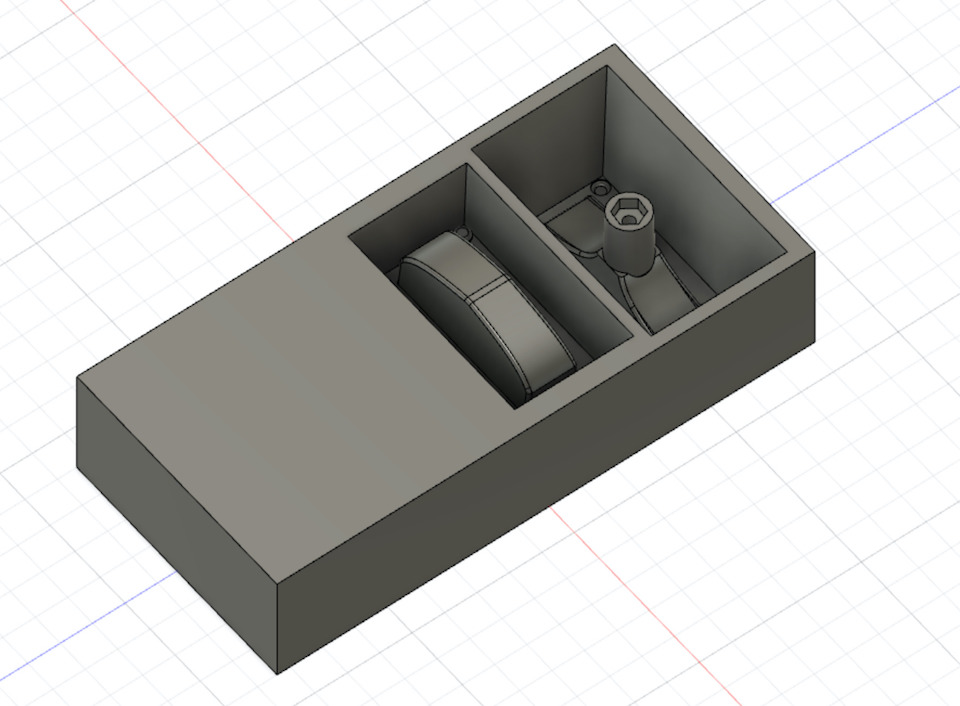
Have designed a rectangle and extruded to be the same size of stock and created 2 pockets of about 50mm x 50mm. Then imported the wrench project into this one and unlocked the model to allow to move the 2 bodies. Placed the bodies inside the pockets and added also 4 registration keys for alignment (positive in right pocket and respective negative in left pocket).
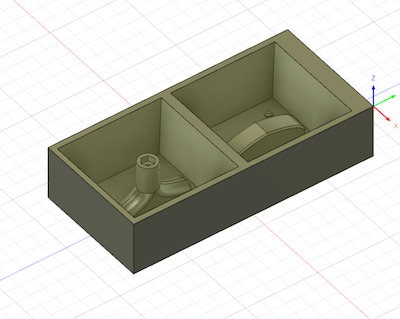
This was the 1st design, and as Filipe pointed, it would remove too much stock material and take a bit of too much time. So it was time for improvements based on Filipe feedback. The pocket walls were also vertical and bigger than end mills shoulder length, so they needed to have an angle (the ~10°). Learned in Fusion how to give an angle to a face by using Draft tool and fixed the vertical walls issue.
The axis orign is the top face, left bottom corner. The design was setup this way so that the spindle collet didn’t it the Carvey placeholders that were securing the wax at the origin. So the pockets were milled on the right side of the wax. My FabAcademy 2020 colegue Marius found the desigs for Carvey CNC and shared then. So imported them to better check how the wax was going to fit.
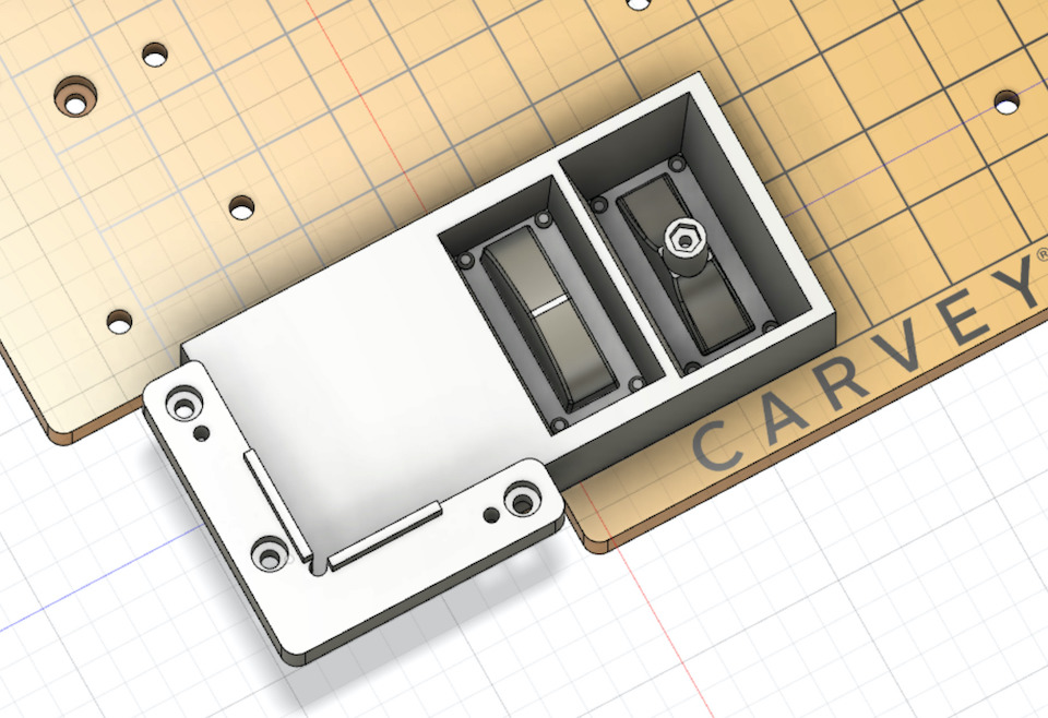
One important thing i noticed was that… didn’t have a sprue to pour in the material into the silicon mold. So needed to add one (small cylinder) on the place i think it’s the best, the base of the wrench.
File: Fusion 360 T-Socket wrench molding
The sprue is at the same level of the top of the stock, so it will be open when pooring the silicon inside the pocket. It will also allow for air to exit from inside the mold while pouring.
Manufacture
With the pockets done, selected the “Manufacture” mode from Design menu.
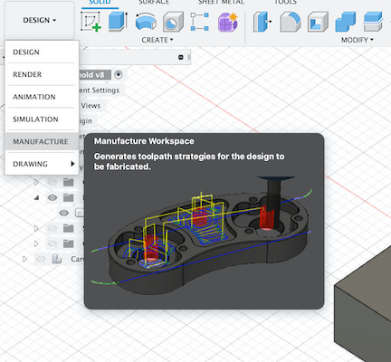
The process is similar to the week 8. Computer controlled machining. Added a setup and started to configure. Selected a “Generic 3-axis” machine and configured the work coordinate system, regarding top face as z-axis and bottom left corner as origin. Selected the design body as Model body.
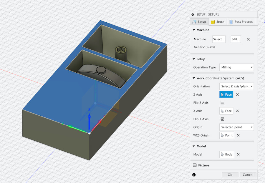
For the stock used “From Solid” more and selected the design body as Stock Solid.

Now for the first rough pass, added a 3D Pocket Clearing work to have a toolpath to make rough milling and remove material in a quicker way.
![]()
Checked Fablab Speed and Feeds Calculator and calculated values for tool and wax, but the result wasn’t ok. A bit too agresssive for the green wax and tool, didn’t break the tool because the stock was machinable wax. Think the values from the speed and feeds calculator should be for a softer wax.
Anyway, updated the Pocket toolpath config with more conservative feedrates (~ half of previous rates).
![]()
For the geometry selected for Machine Boundary “Bounding box” and for Tool Containment “Tool inside boundary”. Then generated the toolpath for the Pocket work.

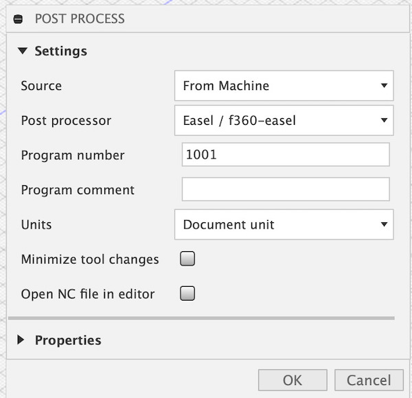
and run the Post-process to save the gcode to then import saved file into Easel (Same software used on week 8. Computer controlled machining, but this time, to run on the Carvey CNC).
After importing gcode to Easel and started the milling process, all looked good. So i let the machine run for some time and keep checking. But there was a bit of a problem. While milling the 1st pocket, because of the design wasn’t only 1 body, i accidentally left the base of the object out of the path and didn’t notice in the simulation.
So released the stock from the CNC and used the bottom face (other side) that wasn’t yet milled, hopping that the depth of the material removed wasn’t going to be a problem.
This time i joined the 2 design bodies updated pocket work config and had only 1 body selected. Re-generated the toolpath, post-processed to get gcode, imported to Easel and started milling.
![]()
It was really looking good! Until the point where the previous error on the other side became obvious and there was no more stock to mill, so the pocket was transformed into a hole. But no worries, lesson learned. Modified the design to remove/hide the 1st pocket, generated the toolpath just for the 2nd pocket, post-processed, imported to Easel and started milling.
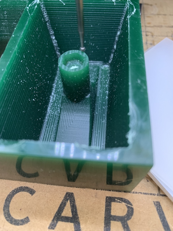
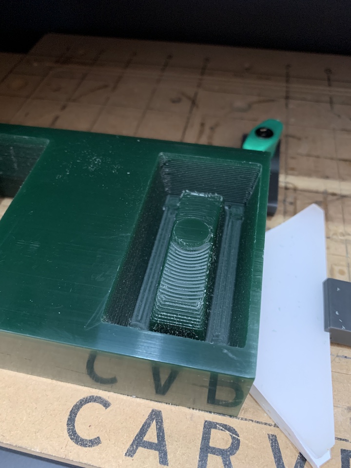
For the 2nd pocket, the 1st pass was ok! Rough pass, done with success.
![]()
There are some issues with the collet at the corners, because of the depth. This is something to improve on the design to prevent or should have left 2mm more of the tool outside of the collet to have more reach (small mistake because it’s wax).
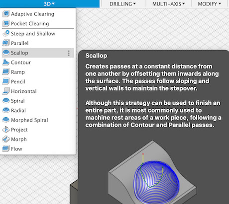
Now for the next step, added a 3D “Scallop”, this is to make a 1st pass on the way to have the surfaces more smooth.
In the setup of the tool, clicked “Select…” to then select the Lollipop End mill. Maintained the same configuration for speed and feedrates.

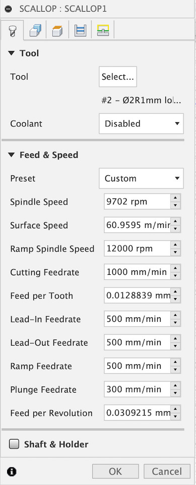
And enabled also the Avoid/Touch Surfaces in Geometry setup for the stock top surface.

Generated the Scallop toolpath.
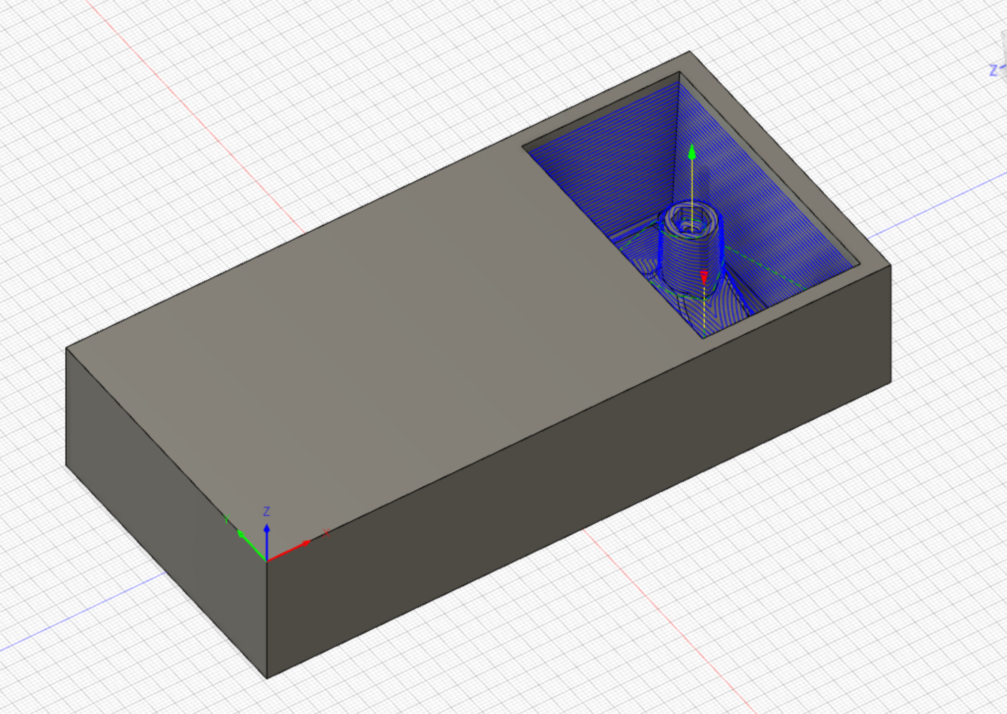
Run the post-process, imported post-process file to Easel and started milling.

It’s easy to see the difference of previous pass and Scallop with Lollipop End Mill, a bit smoother. This step was ok once finished!
So proceeded to what would be a final step of milling for this pocket. This was done by addding a 3D “Parallel” toolpath. In this step also used the Lollipop End Mill to try to have a good smooth finish.
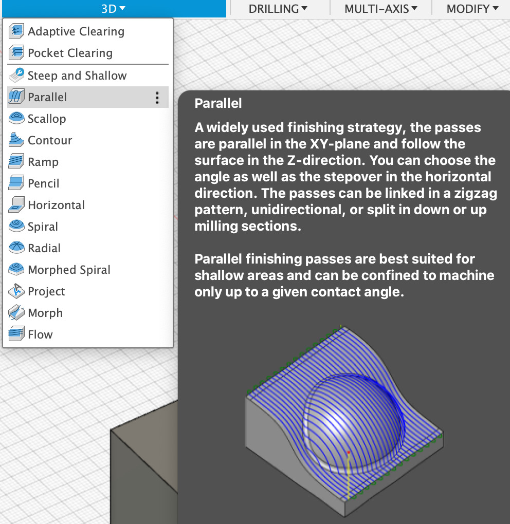
The setup if based on the same parameters used previously for speed, feedrates, also with Avoid/Touch enabled for stock top surface. Generated the toolpath

In the image below shows the beginning of the Parallel toolpath. These passes on same small steps with round tool will make surface more smoother.
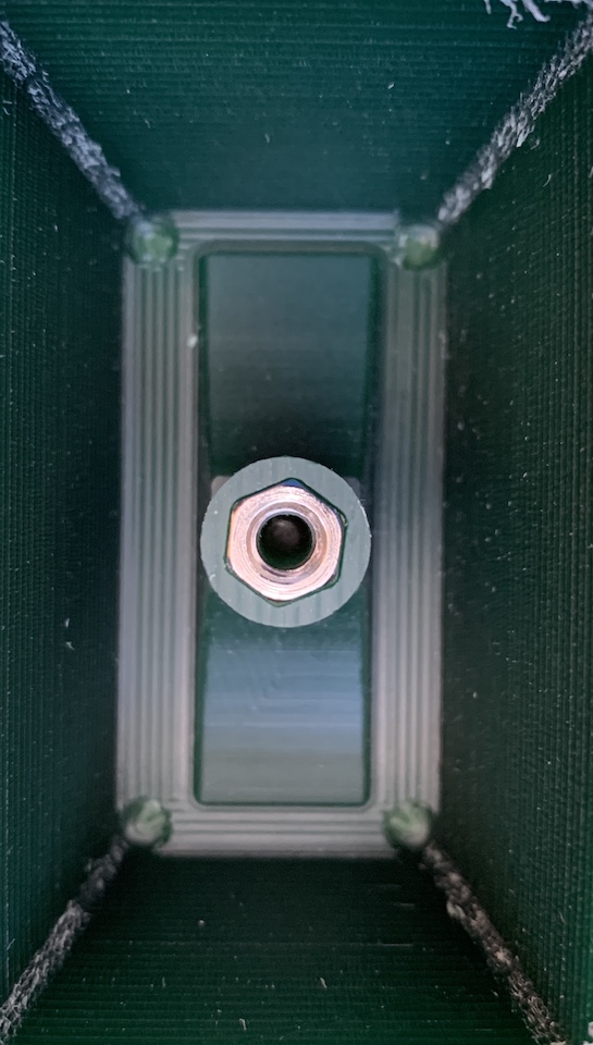
Test fitted the M5 nut in the socket, it was a good fit :)
After being ok with the finish of this pocket i repeated the process for the 1st pocket (then wrench base).
Adjusted the design to have the 1st pocket on end of the stock, because needed to use the part of the wax that wasn’t yet milled. All the previous setup parameters and configs were used the same way for Pocket Clearing, Scallop and Parallel passes with respective selected tools.
** 1st pass with Pocket Clearing **
![]()
** 2nd pass with Scallop **
** 3rd with Parallel **
So once the toolpaths were finished the result was good and mostly smooth! Happy and managed to replicate the steps without problems.

Note
In ideal conditions, with full wax stock available with out holes, i would update the design so that the toolpath work is done with both pockets being milled. Now that the steps are defined, it’s more easy to replicate the milling in ideal conditions.
Creating the Molds
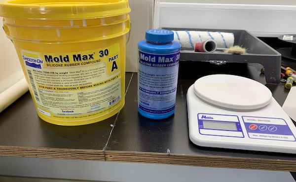
Now to create the mold in silicone. The material to use is Mold Max 30, which is composed of Part A and B.
To know aproximately the weight of each mold, have created 2 bodies in fusion that represent the 2 parts of the mold (1 for each pocket). This way i can use Fusion to give me the aproximate weight for a volume of water (type of material added into the bodies), by checking the bodies “Properties”.
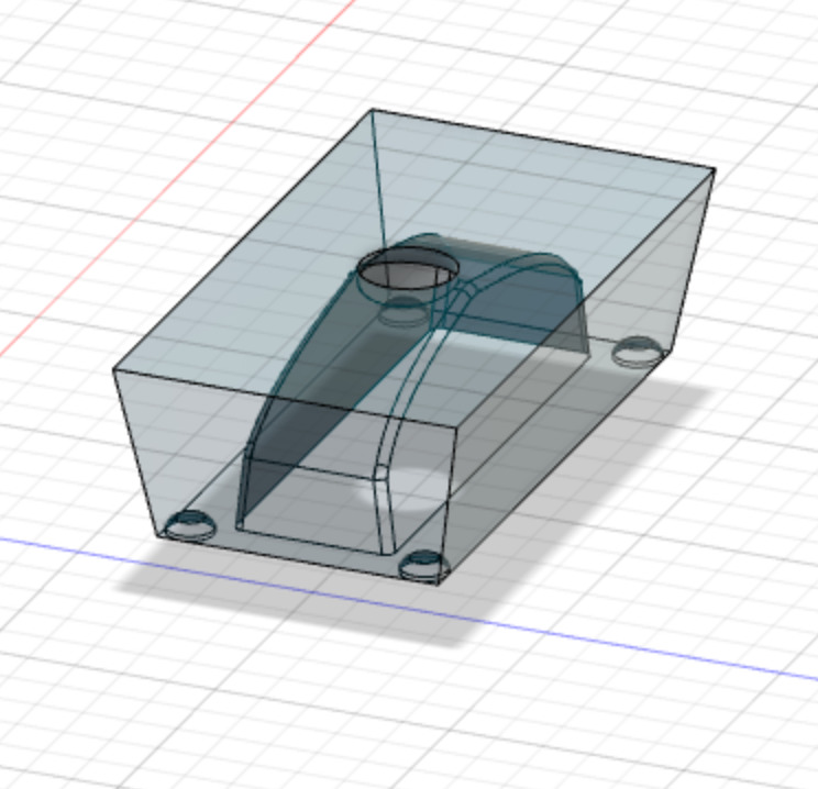

| Description | weight |
|---|---|
| Base pocket | 28.236g |
| Top pocket | 74.133g |
| Total | 103g |
Decided to mix a bit more than needed (some of the material can be left in the wals of the cup). So for Part A added into the mixing cup 130g and into another small cup 13g of Part B. For Mold Max 30 the parts are mixed in 100A:10B ratio.
After mixing the 2 components well by stiring back and forward in the mixing cup while trying not to get air into the silicone, trying to mix all the white from the bottom and walls of mixing cup, it was time to remove the air from silicone by puting it into the lab desiccator.
After “poping” the bubles the silicone was poured into the wax pockets. The wax was previously put on top of a vibration plate to help to release any remaining air bubles while silicone was curing.
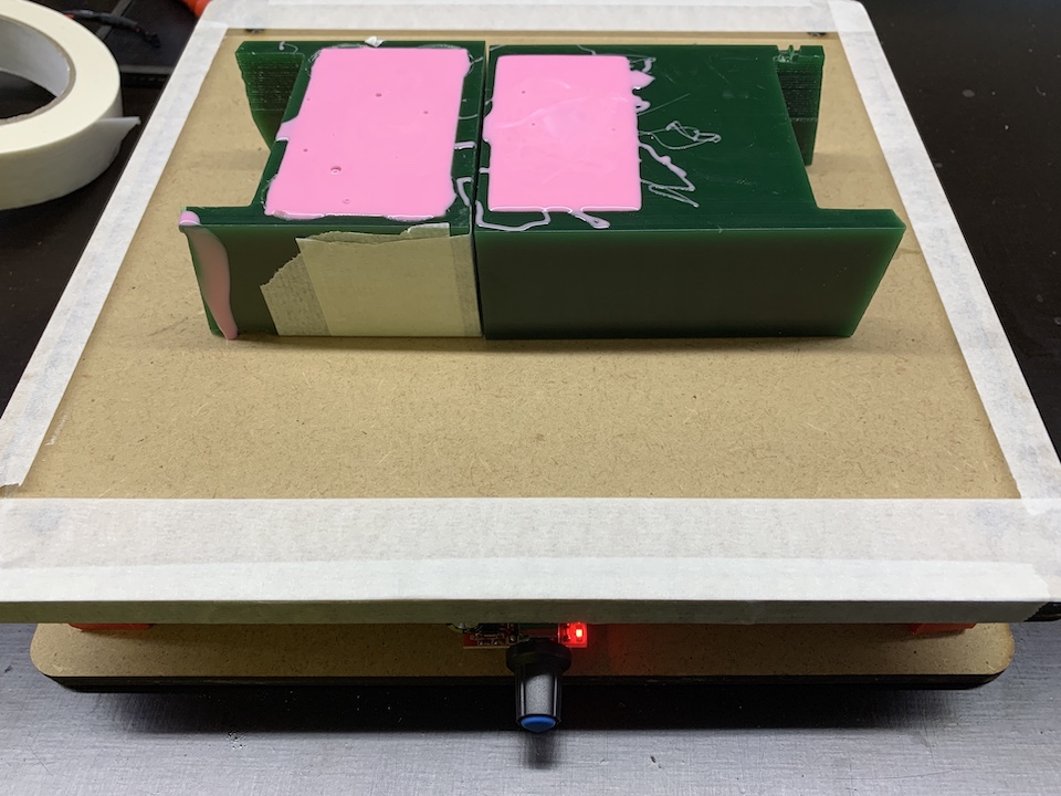
The silicone was left overnight to cure and in the next day have remove the silicone from the wax.
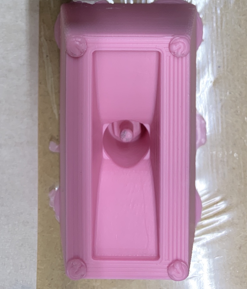
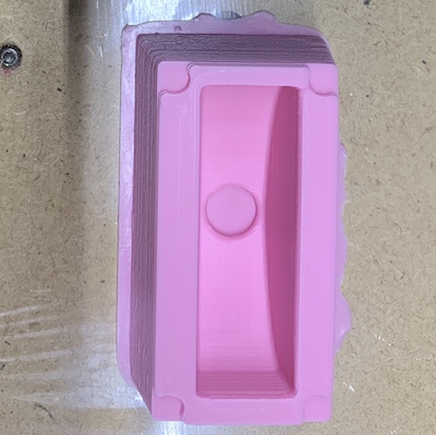
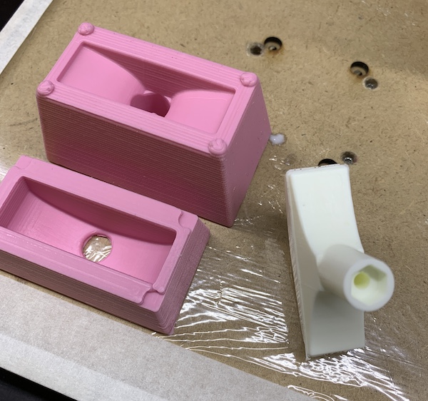
The molds cure was ok, there were no visible air bubbles holes. All good!
Casting
After having the molds, Filipe provided 2 small MDF plates and a rubber band to keep the 2 parts of the mold locked and aligned while pouring the resin.
So for casting, the material used was Smooth-Cast 300. This is a liquid plastic 2 part mix (A and B) with a ratio of 1A:1B.
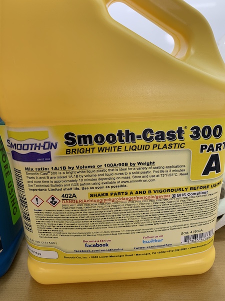
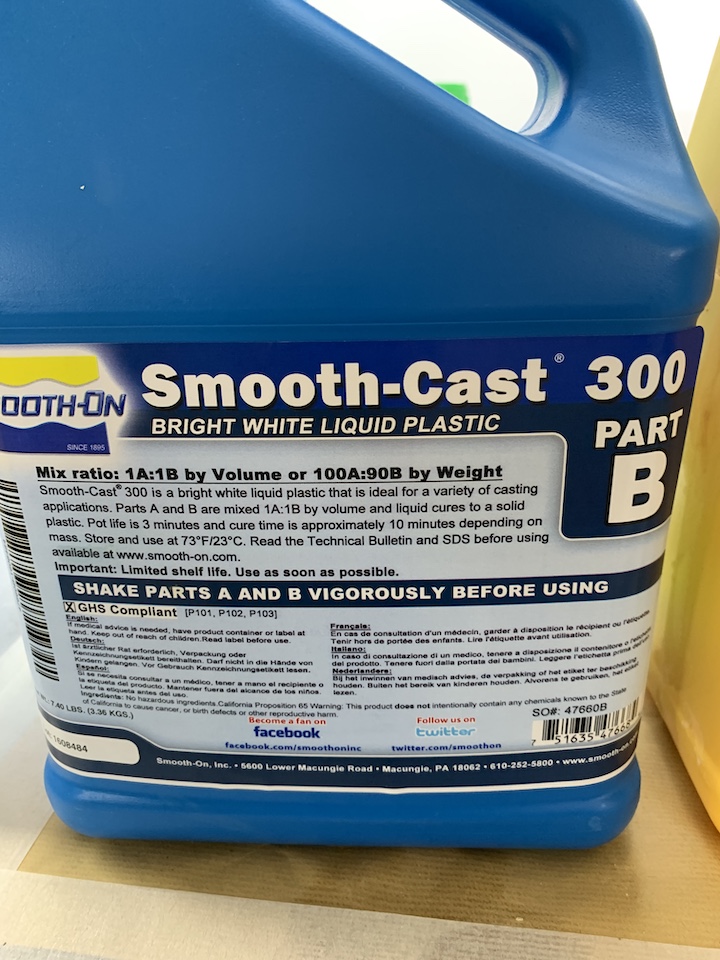
From the Fusion wrench design i check for the Mass in properties of the body with material type “water”. The weight of the wrench is ~18.649g.
Decided to mix for a total weight of 24g, so this means 12g of Part A was poured into a small cup and 12g of Part B was poured into another small cup.
The mold was then added into the top of the vibration plate, timer countdown of 1 min started, poured the small cups with Part A and Part B into a mixing cup and stared mixing back and forward. Tried to mix without adding bubbles into the resin, scraped bottom and wals of the cup and before 1min passed, started to pour into the mold (the cup started to get warm).
This is a short timelapse showing the resing curing.
After some 10 or 15min, i removed the MDF and rubber band and the wrench from inside :) (This is quick when compared with 3D printing).
After the casting, trimed a bit where the molds were joined. Think that i should have add 2 more registration keys to make the alignment along the walls more easy. Anyway, happy with the result!