18. Wildcard week
Design and produce something with a digital fabrication process (incorporating computer-aided design and manufacturing) not covered in another assignment, documenting the requirements that your assignment meets, and including everything necessary to reproduce it. Possibilities include but are not limited to wildcard week examples.
Learning outcomes
- Demonstrate workflows used in the chosen process
- Select and apply suitable materials and processes to do your assignment.
Have you
- Documented how you made your creation
- Described problems and how you fixed them
- Included your design files and ‘hero shot’ of the result
Assignment
For this week i decided that i would be used to create the RC car shell. So for this to happen i need to:
- design some car body shell
- create the shell mold by using a CNC
- apply composites process to fabricate the shell
The RC car will have aproximately 750mm (length) x 320mm (width) x 160mm (heigh). Because of CNC limits to remove material in size and form (z axis max height of 65mm), the CAD model will need to be sliced into layers to work. So once the car form is sliced into layers of a height below 65mm, it’s possible to fabricate. In the end i will join back the milled layers to have a full size mold to work with composites.
*** Note ***
Because of COVID-19 pandemic and lab being without access for some time i decided to buy and mount my own “big” cnc at home (perfect excuse :) also I had already done this for the small CNC to mill PCBs)
Bought the OpenBuilds LEAD CNC Machine 1515 from RatRig a local supplier and assembled it.
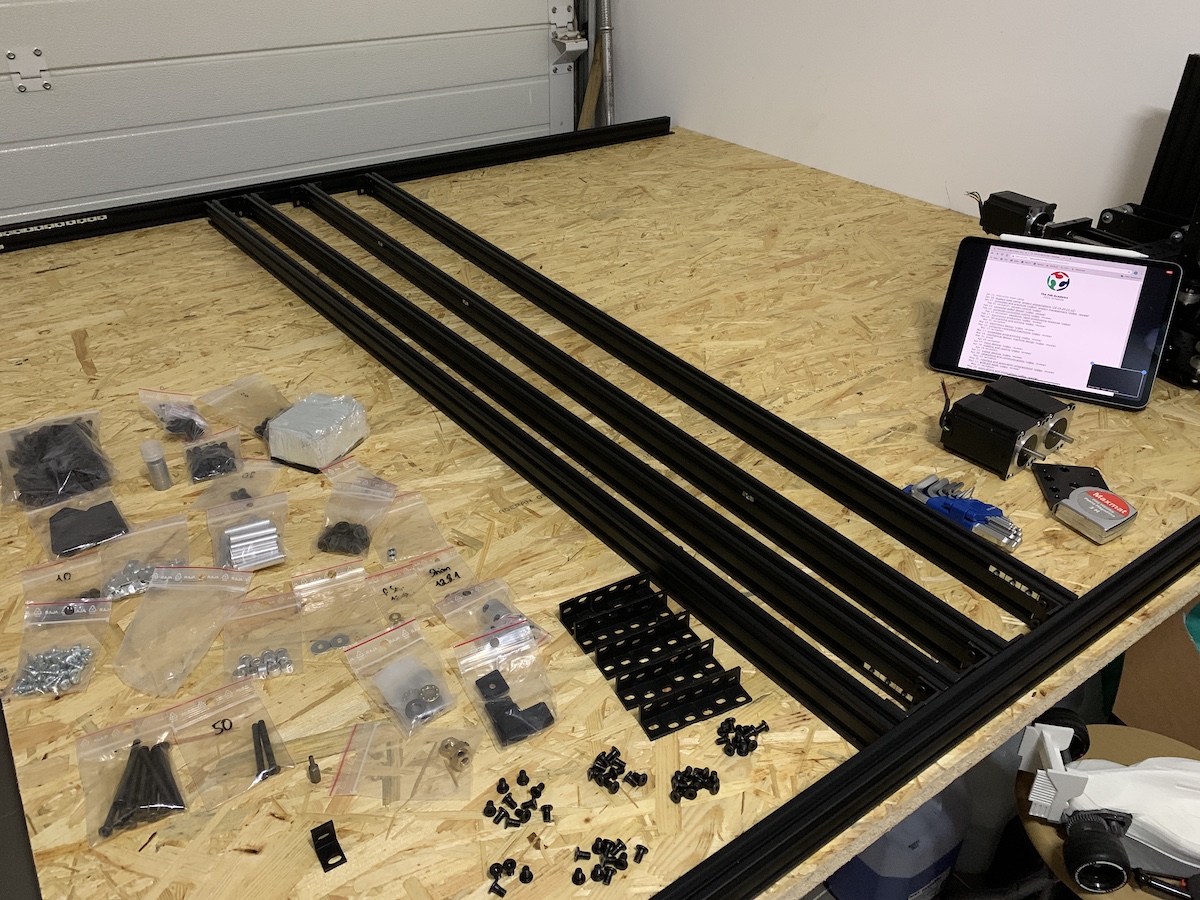
Looking good!
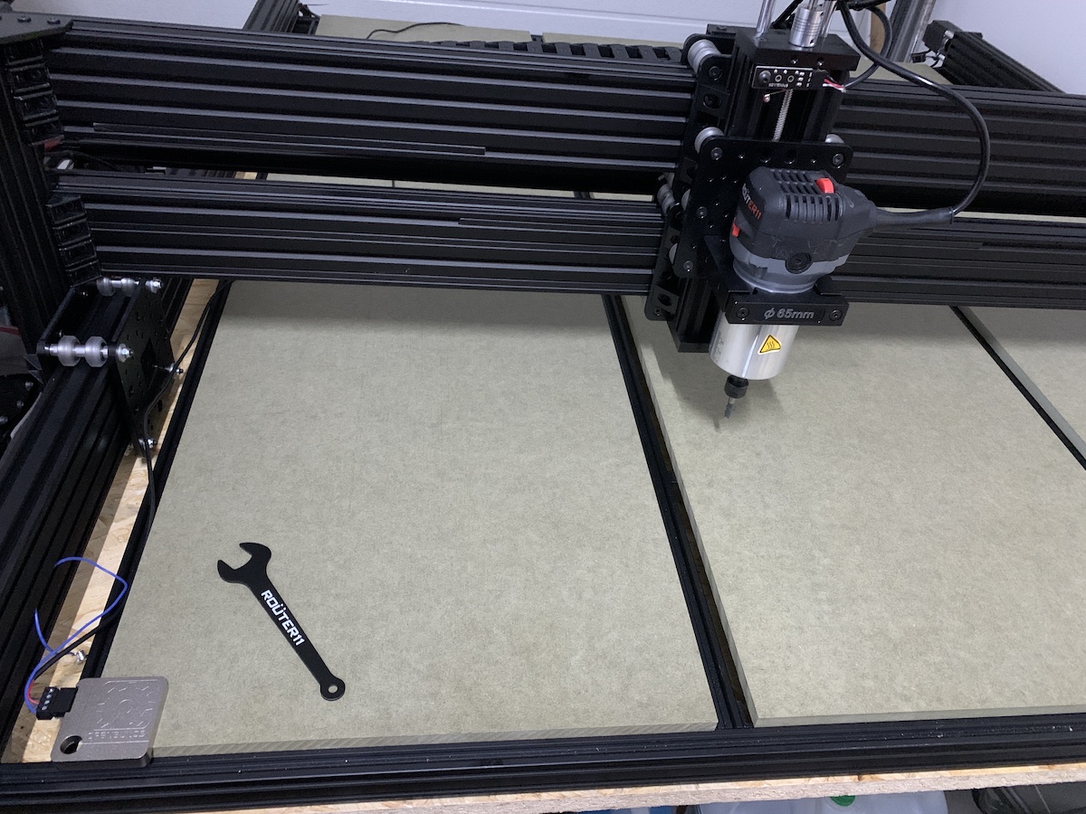
1st tests and homing didn’t went ok, some wiring to check and tight. But after making sure all was well connected, measures were correct and frame square and tight, all was good to go mill.
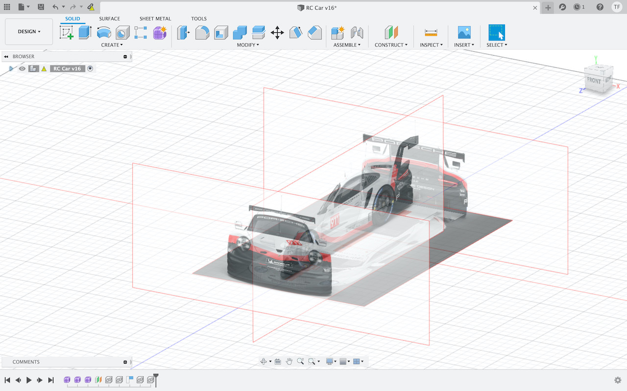
Car shell design.
For this i tried to use my “not so good” sketching capacity :) to try to decide on a form for it.
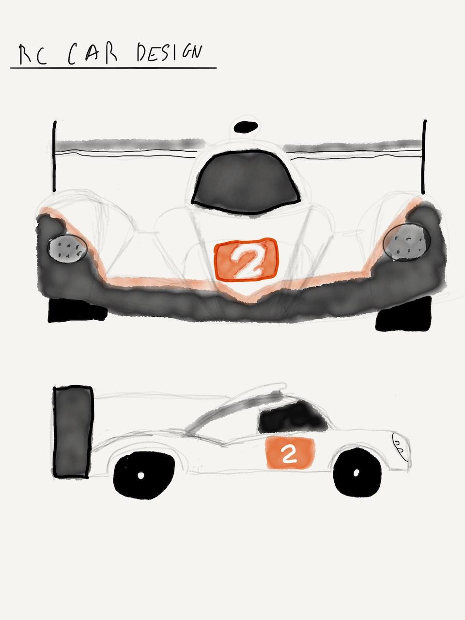
Some Le Mans race inspiration…
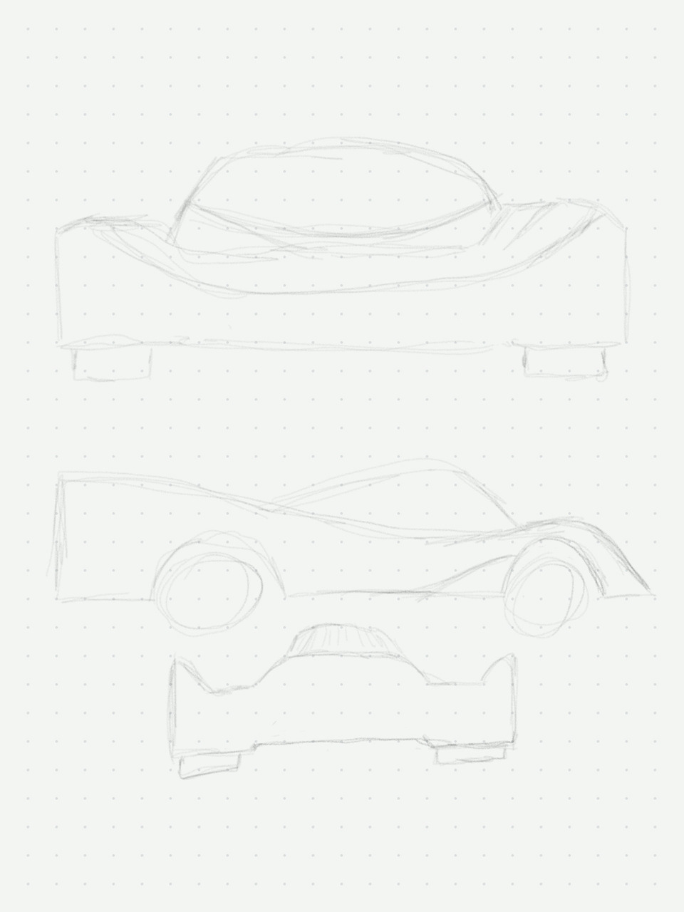
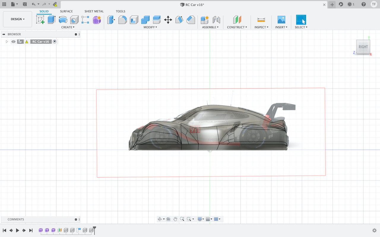
This sketching activity was only to spike some inspiration and decide what/how should i need to do and learn to design the shell. This is “new territory” that i’m exploring for this week assignment. After some research, found that fusion has the Form/Skulpting Mode. Started to play around with it until i found/learned some way to have some shell design done.
In Form mode you can add canvas in different sketch planes with images. These if adjusted to the model size that is to be created can serve as reference point to make the design, by pulling and pushing lines and points “on top” of the images (like paper drawing copy).
So after some iterations in the design…
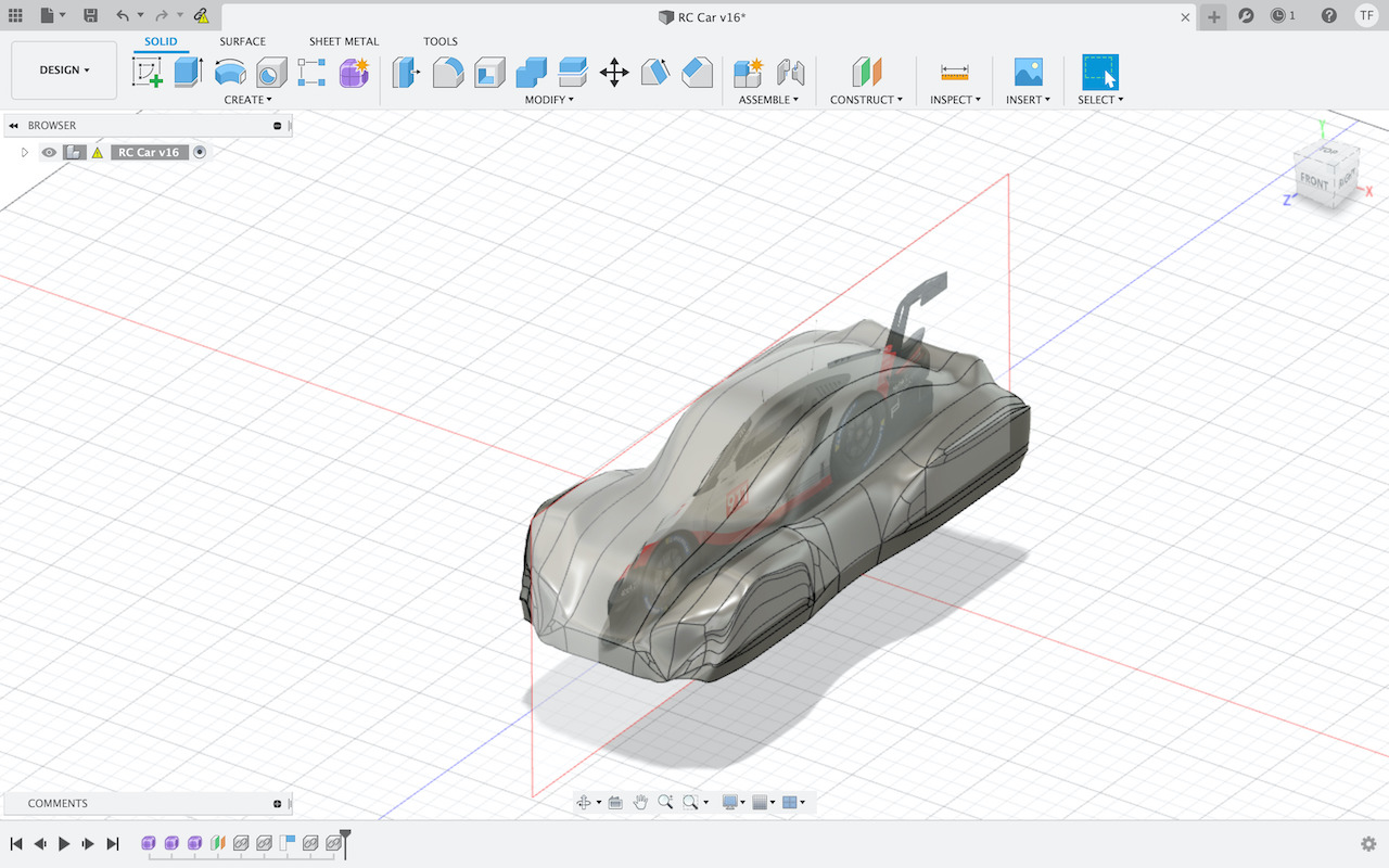
These are some renders of what could be the shell base to be used to CNC some foam or other soft material to then create the shell mold.
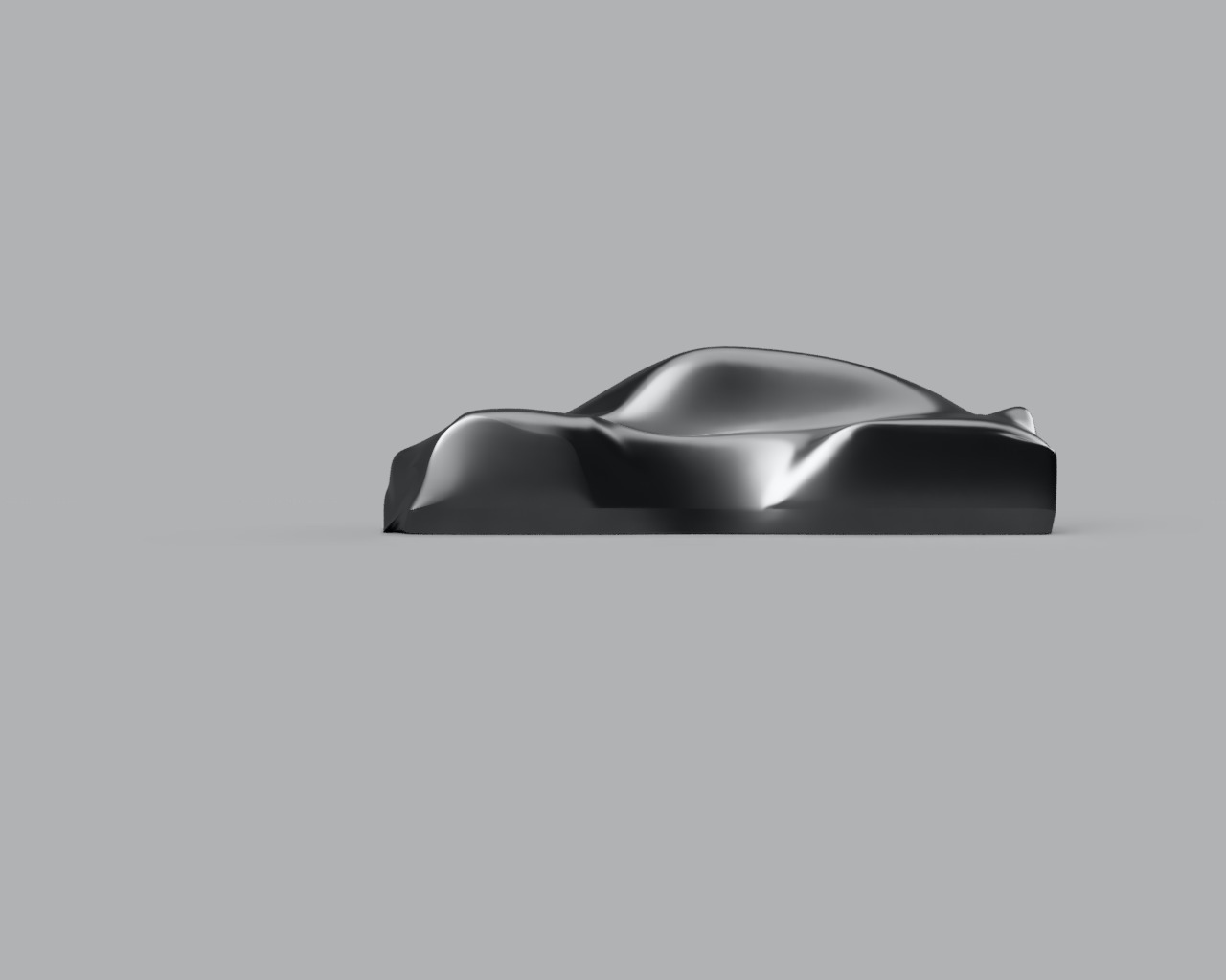
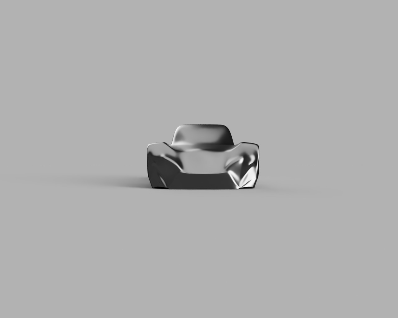

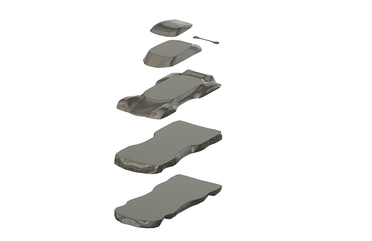
After some more tweeking/adjustments (whish took “ages” to make) to the car form i was happy with final result. From here i needed to convert somehow the faces form into a solid object so that i could then cut into layers with specific height, so that they work with CNC and bit capacity for milling (maximum milling Z height is an issue, car height is ~16cm and ).
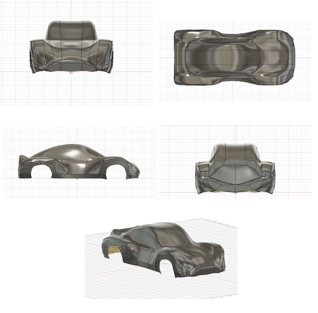
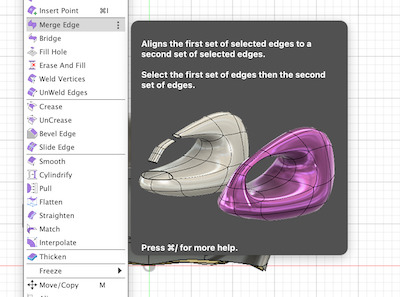
So to have a solid object from a form, the form object needs to be “closed”/”water tight”. I did use FORM -> Modify -> Bridge tool, Merge Edge tool and Fill Hole.
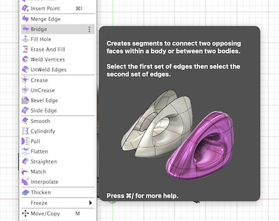
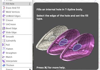
so that i could slowly made the form “water tight”.
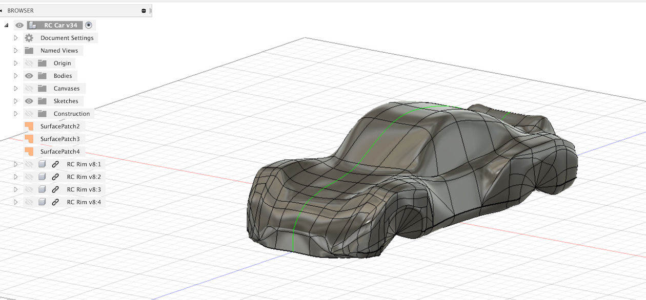
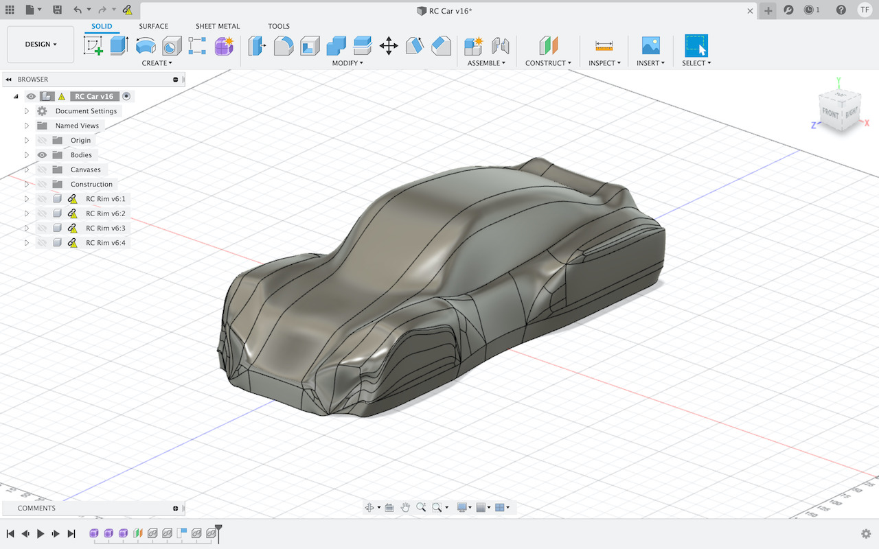
Once this was done, managed to convert the form into a Solid body.
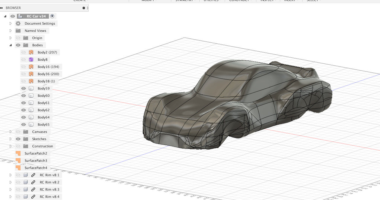
And this allowed to create 4 “Offset Plane’s” to be used and tool to cut the solid in layers so that if could be milled.
All middle layers have 40mm heigh.
Links
- Car Design Speedrun 5 - Using Autodesk Fusion 360 - supersport GT
- Fusion 360 T-Splines tutorial Part 1: the basics
- QUICK TIPS: Sculpting Tips
- Surface Modeling with Fusion 360
- Fusion 360: Turn Surface Body into Solid Body
Car mold
*** Material ***
This time for milling material i choose foam (Extruded polystyrene (XPS)). From FabAcademy CNC Tips, foam is one of the materials recomended to use. It should be “easy” to mill.
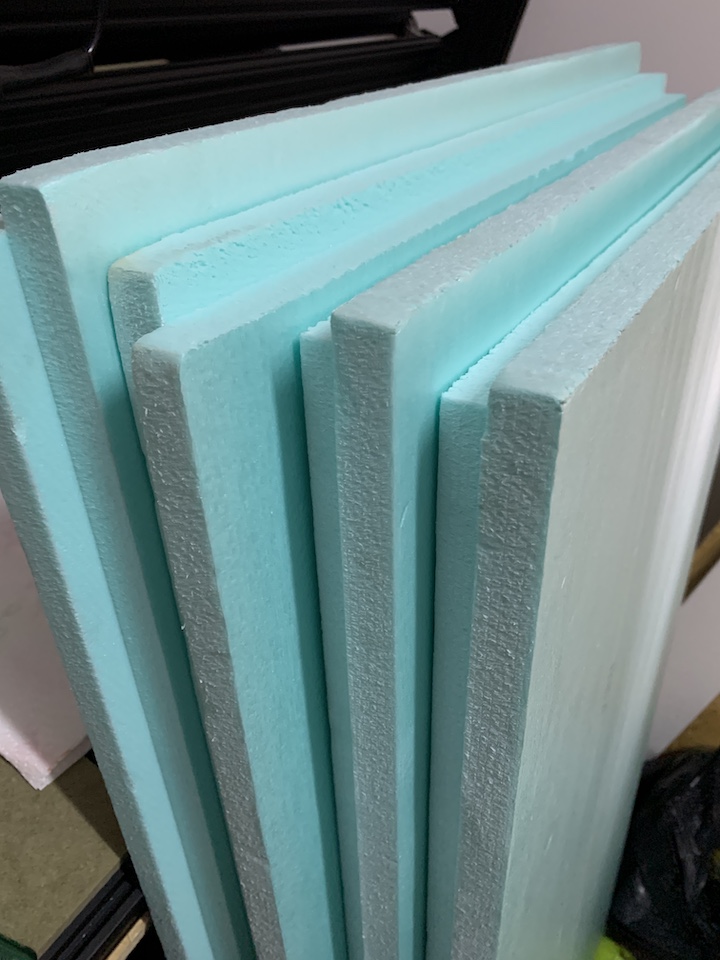
On my case i’m using XPS boards of 1250m x 600mm x 40mm. They have the correct height of 40mm for designed car layers.
The tool for milling is a 2 flute Carbide Ball End Mill of 6mm diameter, 12mm flute length (overall length 75mm).
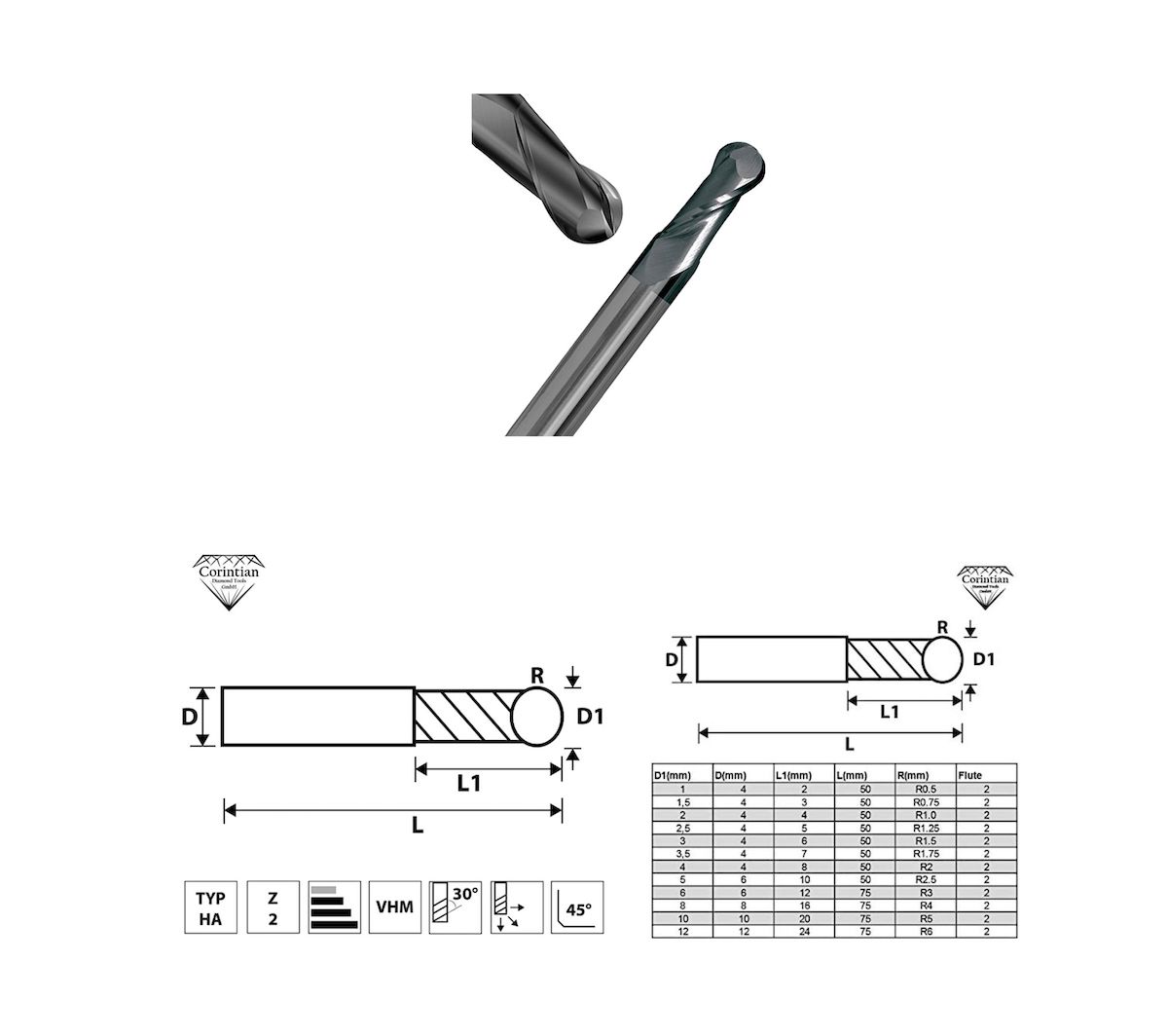
Have configured this tool on Fusion 360 Manufacture mode to be used on setup and milling paths generation.
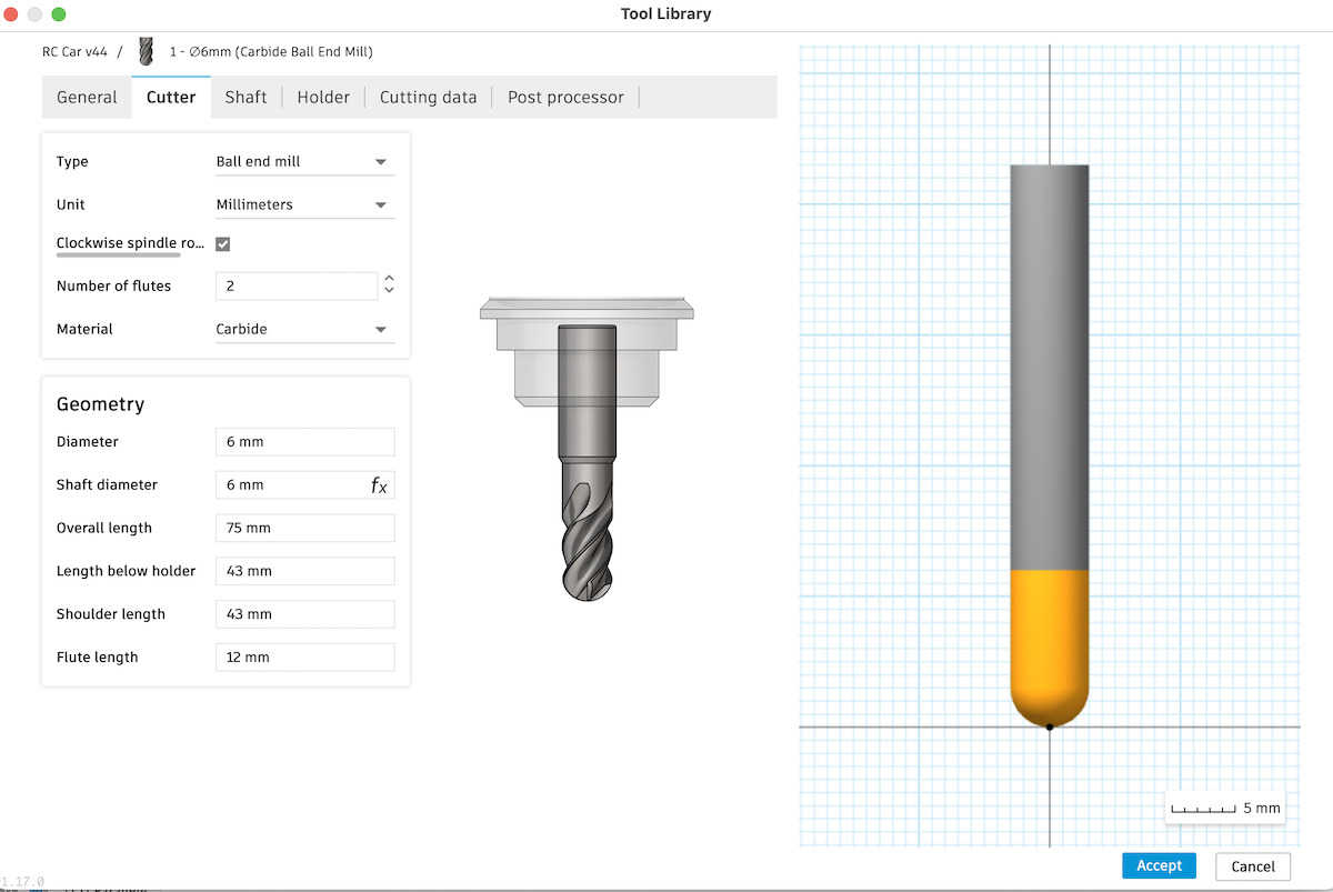
For the “Length below holder” i’m setting to 43mm, which is the same length used to mount the tool on the router. This makes it possible move the tool to max z height on cnc without hitting the Z limit switch. And also to mill the 40mm height foam all through z 0, without hitting router collet.
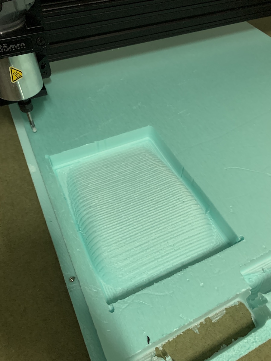
*** Testing ***
For 1st test used the smallest or the layers to make some test setups and paths. So the smallest layer is the one in the car back spoiler.
Created a setup for it
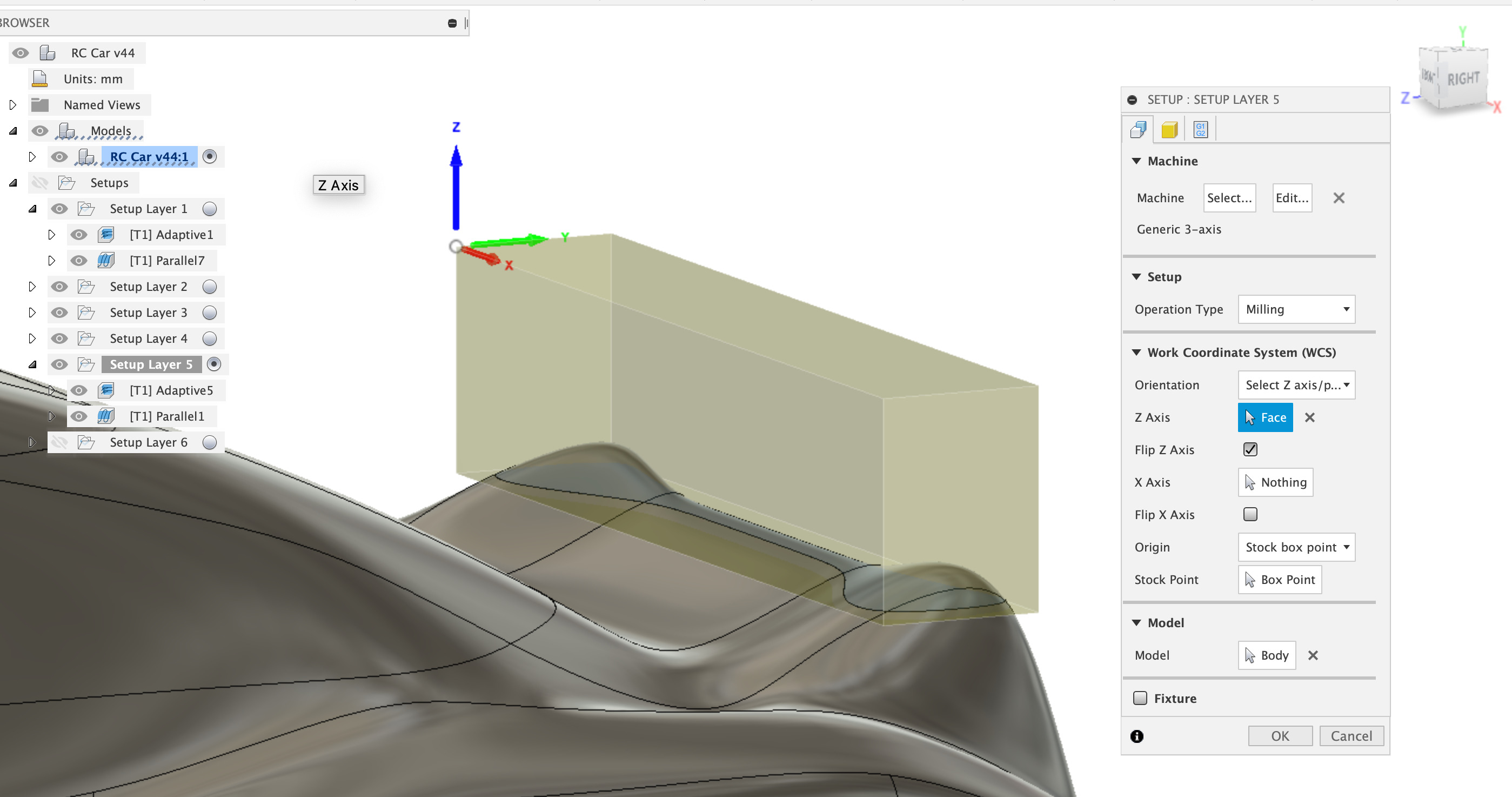
This means setting the correct Machine, Operation Type and coordination system for the selected body. Selected a “Generic 3-axis” machine for milling operation; selected “Z axis/plane & X axis”; selected the Z face, on my case needed to flip Z also, i’m using top left corner as stock point and on model selected the respective small spoiler body.
Then clicked on the  tab to setup the stock to be milled.
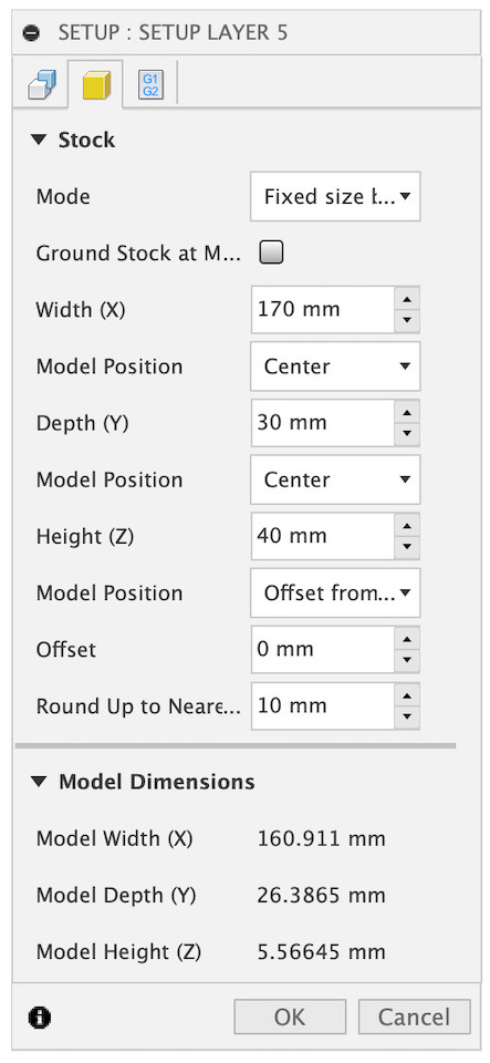
Height of the stock 40mm and the width and length adjusted to the selected body part. For this i also set the model Z position in the bottom (-Z) with 0mm offset. Foam will all be milled leaving the spoiler part.
For a 1st paths i tested foam milling with
![]()
and
To configure the paths i used conservative milling feeds & speeds.
![]()
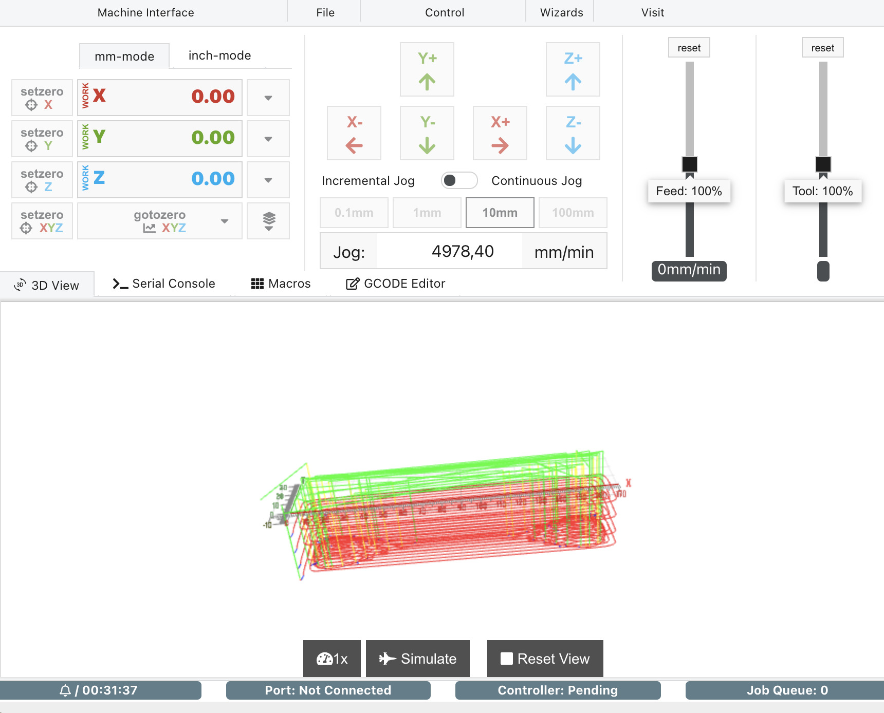
At this point needed to run the “Post process” on the “Setup Layer 5” to generate the code specific to the OpenBuild LeadCNC 1515. Followed this tutorial to install it on Fusion 360: Fusion 360 Post Processor to support OpenBuilds BlackBox and OpenBuilds Machines.
From here i connected the laptop to the CNC and open OpenBuild Controller and open the generated code. Did a x,y and z probe with touch probe on top left corner of foam and did 1st milling and hit play button.
While moving up in Z, over stock, the Z limit switch was triggered… needed to adjust the path “Clearance Height” so the limit switch wasn’t triggered in this situation. Reduced “Retract height” from 10mm to 5mm.
![]()
Alert… milled more than it should…
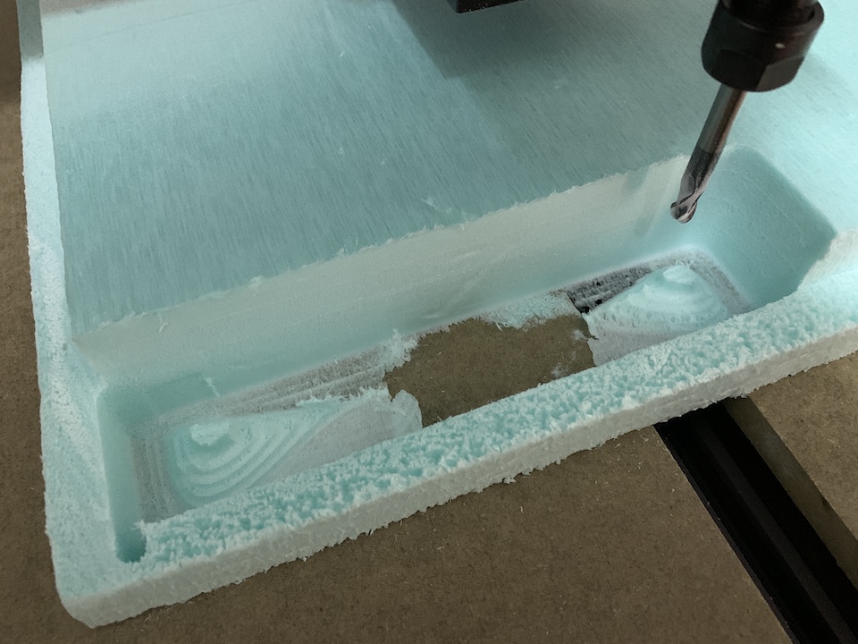
Need to make some fine adjustments, leave more stock eventually for 2nd path…
and the result was better
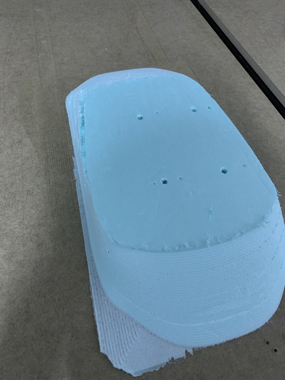
Next tested with car layer 4 and used  , this time i didn’t have the stock at the bottom, was just a milling test so milled at the top of the stock.
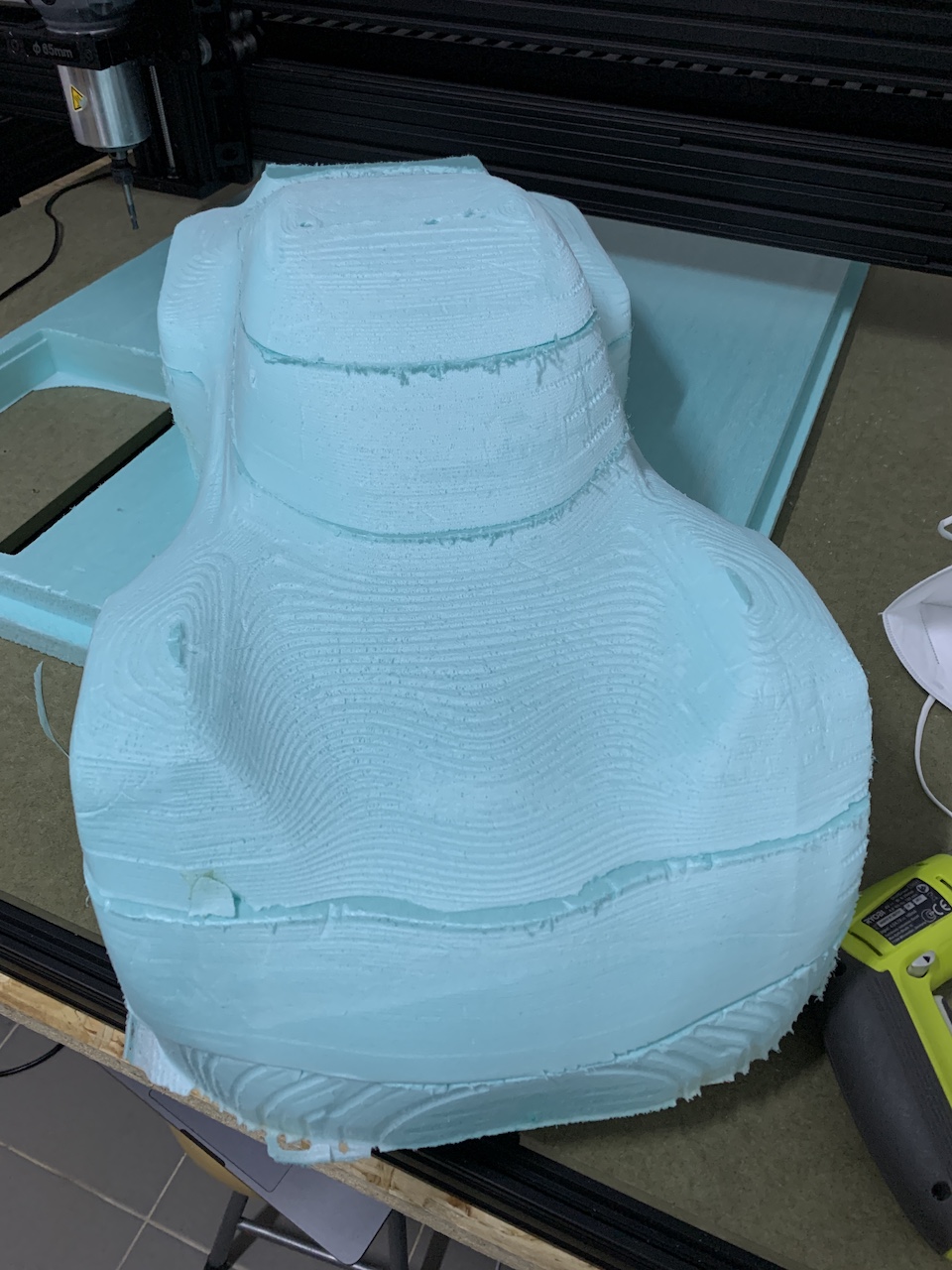
Now lets go work on final settings and mill all car 6 layers to have a mold…
Milling the 6 layers
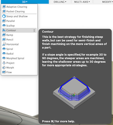
To mill the 6 layers i decided to just use the Adaptative Clearing, the final result was good enough for the milling and expect to do some manual sanding/finishing once the layers are stacked and glued all together.
Settings for the Adaptative Clearing Passes:
![]()
Let go to work… so each of the 6 layers were setup on Fusion 360 project
![]()
and “Post Process” to generate the respective .gcode files for each layer: layer1.gcode (bottom layer), layer2.gcode, layer3.gcode, layer4.gcode, layer5.gcode and layer6.gcode (top layer).
The milling process
Note on Layer 4
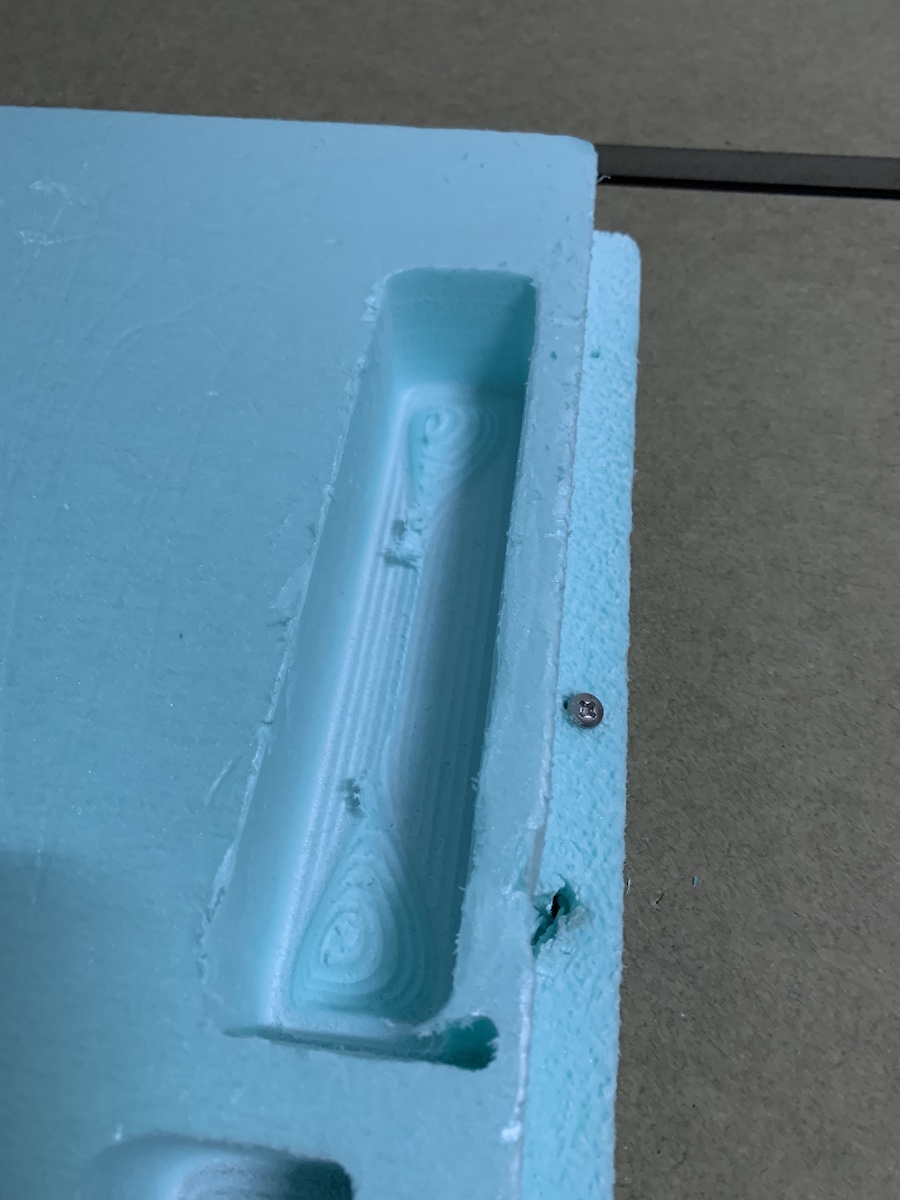
Small “fail moment” at the end, retraction wasn’t configured to be above stock, so when returning to HOME, the tool touched the layer and made a cut.
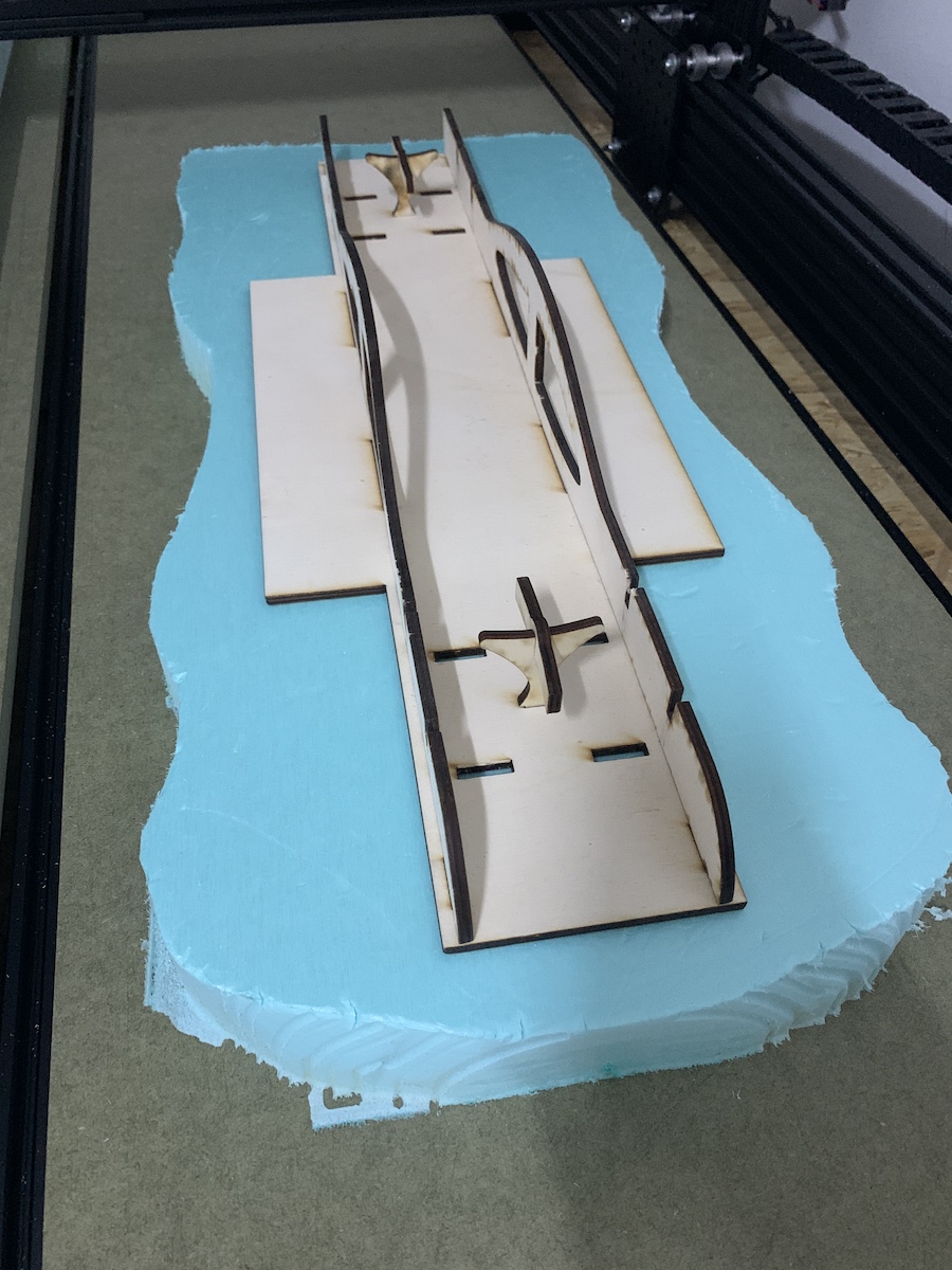
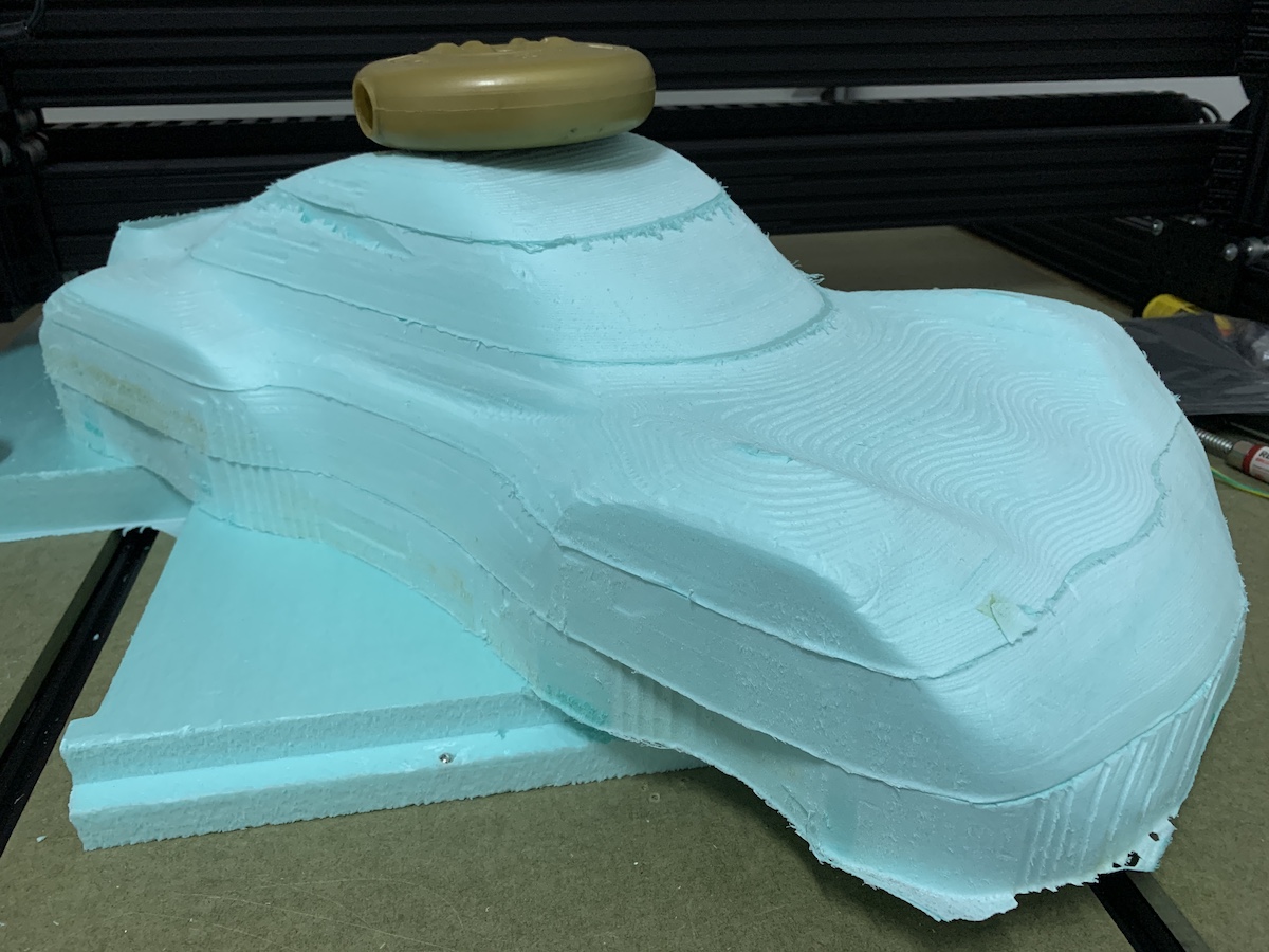
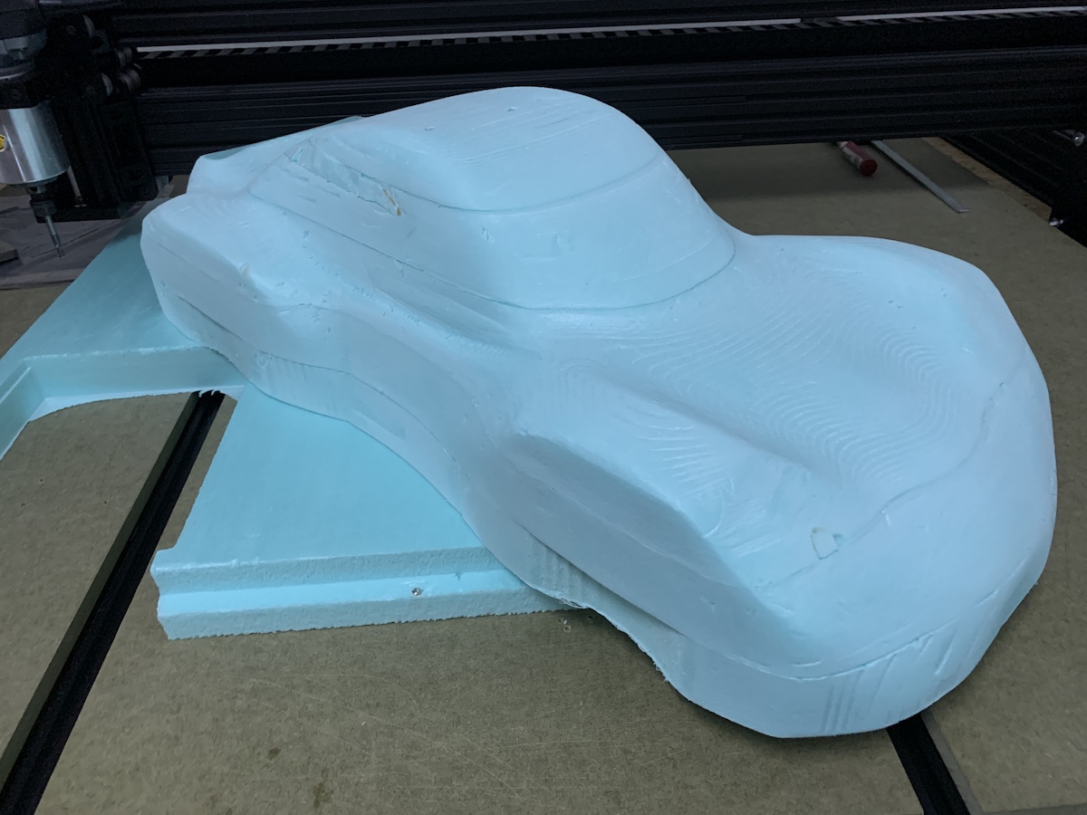
Scale/Size check
Check the size against the car chassi, looks like a good fit :)
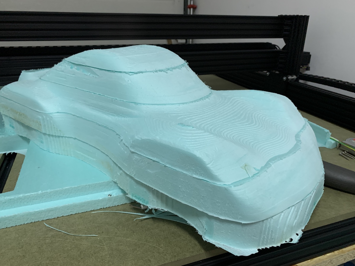
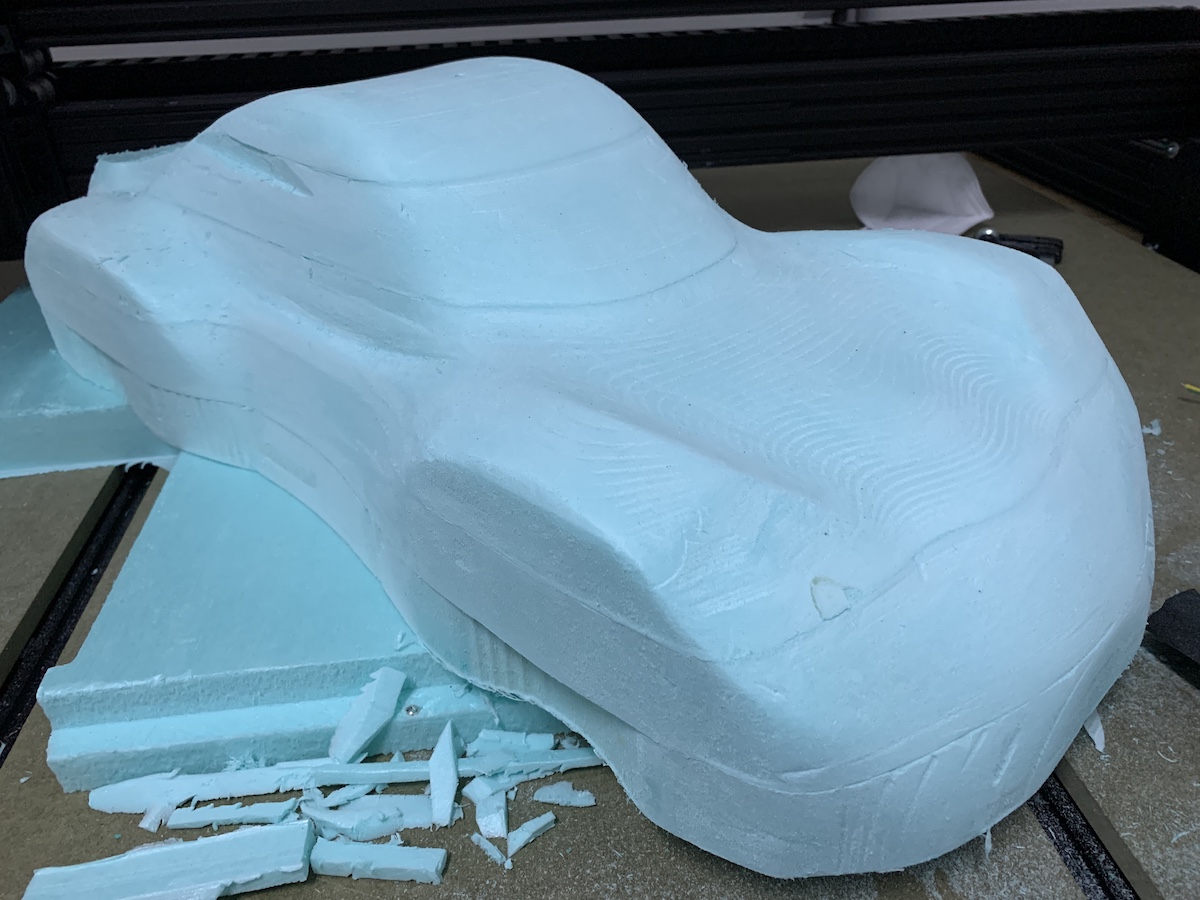
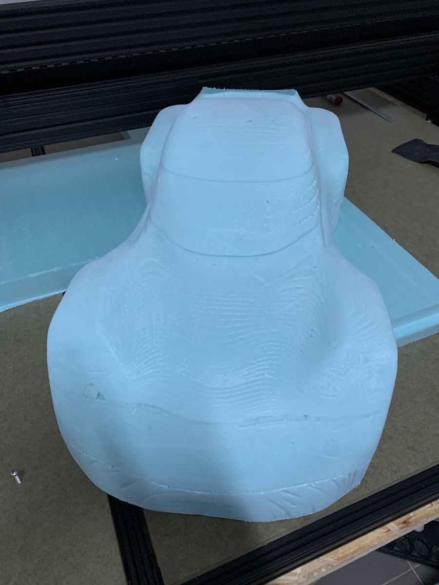
Final Milling Result
It needs some sanding and cleaning, XPS in some thin places needs some attention while holding because it can break easily. At the moment i think i can work with these layers.
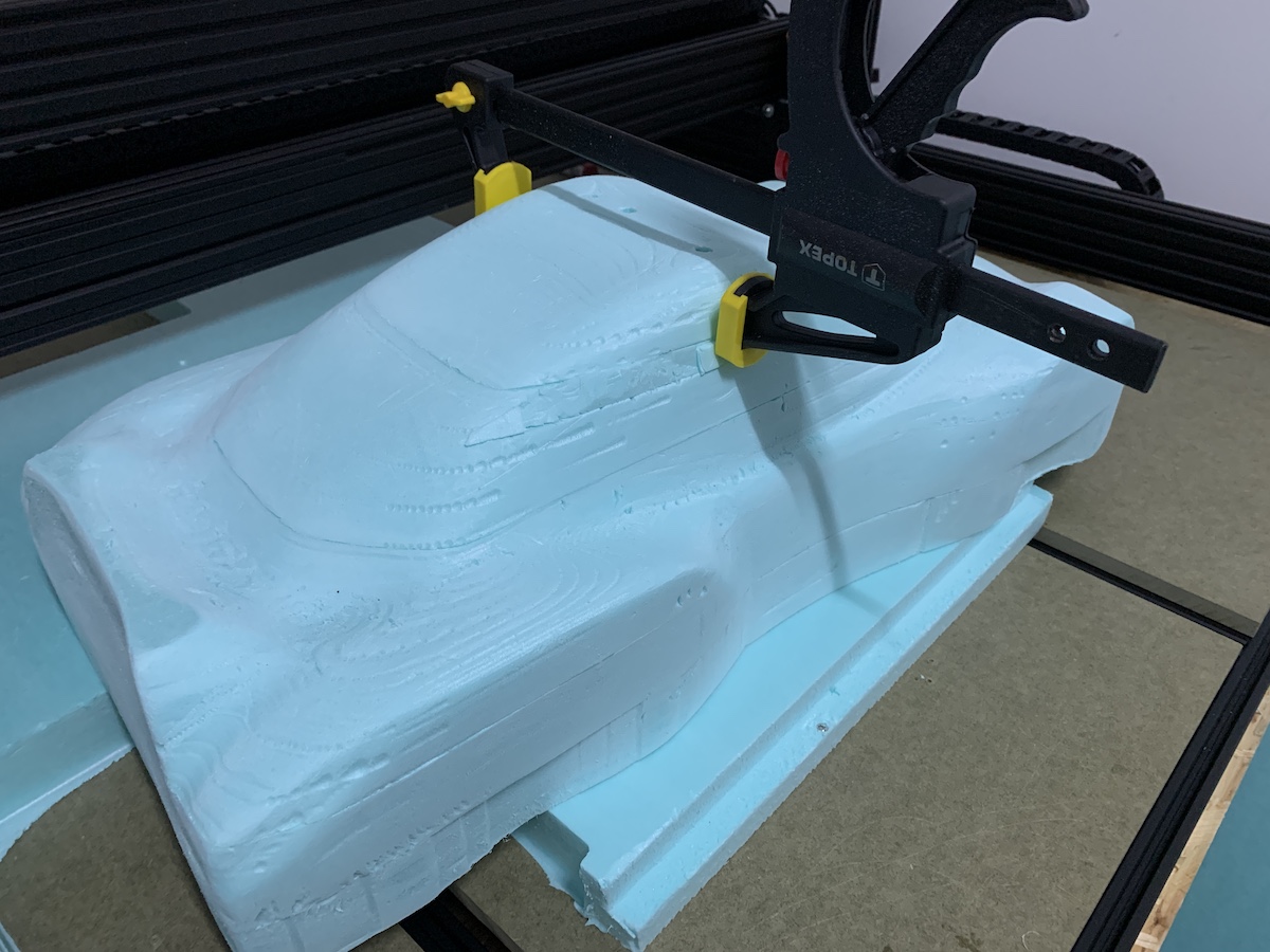
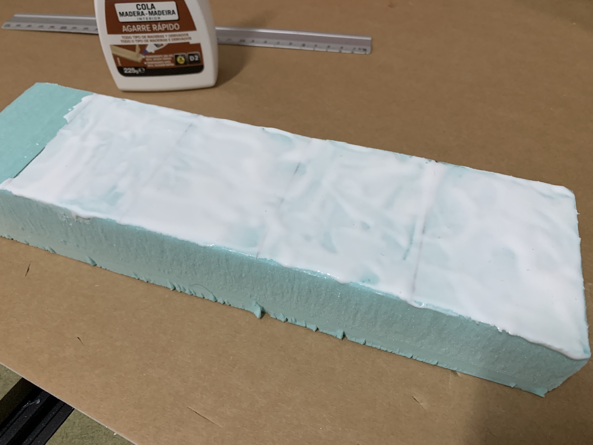
Gluing and sanding layers
After milling the next step was to glue layers. Used wood glue, this is what i had around that could also be used to glue XPS.
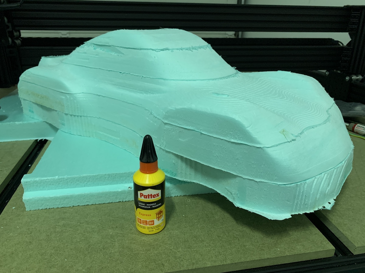
and then sanding. Did the initial passes on the XPS with P220 Sandpaper to remove a bit more of the imperfections in the surface. Then finished with P800 sandpaper to try to make surface smoother. This step requires a bit of patience.
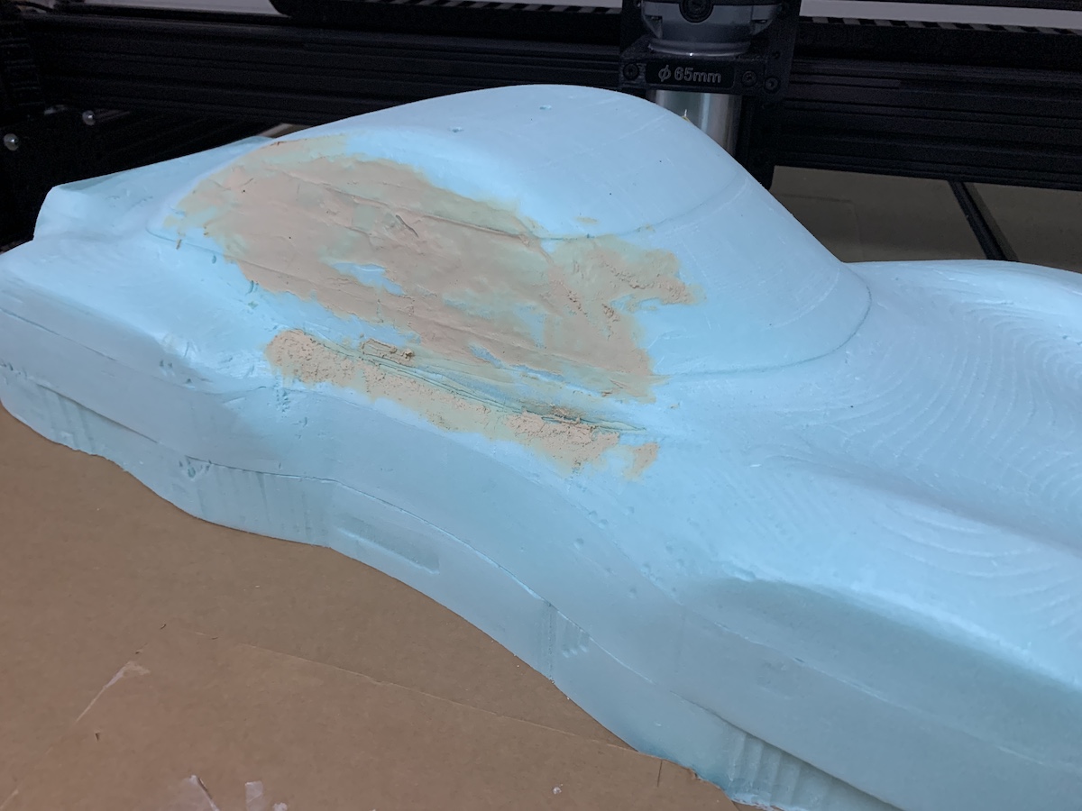
At this point have also fixed a “minor issue” that happen during milling. After finishing CNC job, the router didn’t retract above the stock (at the time this wasn’t correctly configured in Fusion 360 project), so it removed a bit of material from top 2nd layer. This was “fixed” by cutting and filling in some XPS and glue.
To improve this “fix” i also tested the use of car filler with polyester resin on the XPS to fill in the small holes.
Links
- FabAcademy CNC Tips
- Fusion 360 Post Processor to support OpenBuilds BlackBox and OpenBuilds Machines
Composites process
What is exactly the composites process?
To create a composite you need at least two materials: a fiber and a matrix. The fiber (carbon fiber, burlap, etc) are good handling tension and the matrix (epoxy, cement, natural resins, etc) usually a material that is good to handle compression, they are both combined together to create the composite.
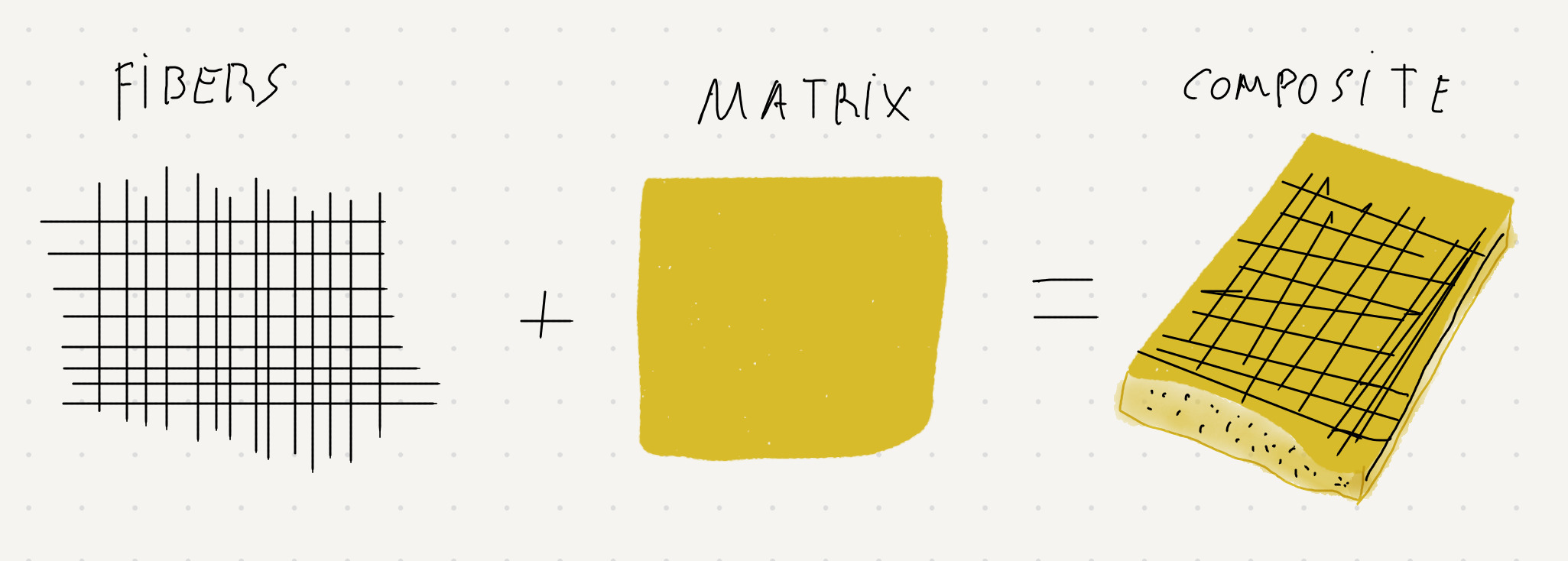
The composite can be created by adding several layers of fiber, oriented in different directions to handle tension in different ways within the matrix and then compacting to keep just the necessary matrix part to hold the fibers in place. This is called lamination.
One way of compacting is by using vacuum. The composite is put inside a vacuum bag, the air is extracted, the bag then compresses the composite and allows matrix excess to bleed out. It’s a good way to have a consistent/replicable composite with just the necessary matrix around fibers and without air/bubbles.
When compacting, the composite is usually compressed against a mold with the form we want the composite piece to be made/create.
The image below shows the “Typical components of a vacuum bagging system”.
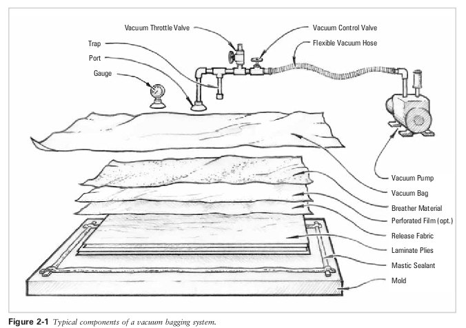
The laminated plies are the layers of the composite to be compressed by the vacuum bag. The release fabric allows to easily release of the perforated film and breather material that will receive the excess matrix from the laminated plies allowing them to be compressed.
| Material used | Notes |
|---|---|
| Nitril Gloves | |
| 3M Mask FFA2P3 | |
| Wood mixing sticks | |
| Disposable Measuring/Mixing Cups | |
| Small Kitchen scale | |
| Vacuum pump + hoose + vacuum bag connection valve | |
| Carbon Fiber Taffeta 3K, 160 g/m2 | |
| Mastic sealing for vacuum bag | |
| Peel Ply, 83g/m2 | |
| Breather Mesh | |
| Bleeding film, 25microns | |
| Vacuum bag 50microns, 80 cm width | |
| Castropox 4307 FLEX / 1209 Resin | |
| ACMOS 82-2405 Release Agent Spray | |
| OSKAR’S Mould Release Paste Wax M 700/C-WAX |
Safety
Please check security data sheet for each material used. Use gloves, mask, protective glasses while working with composites.
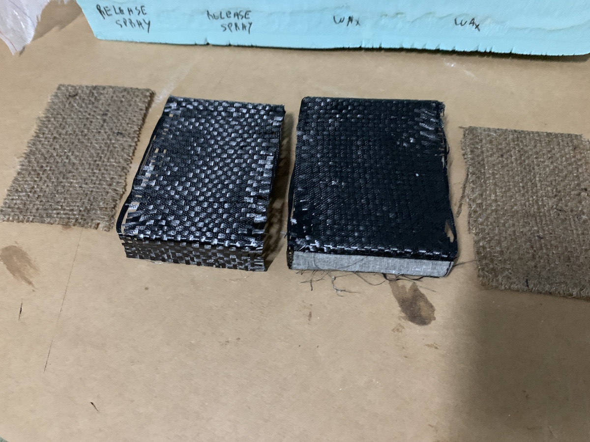
Test Coupons
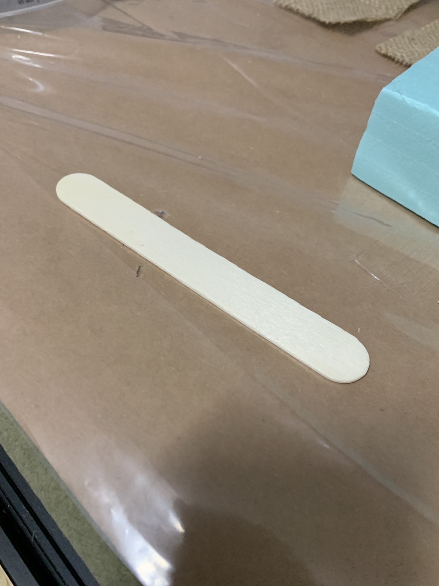
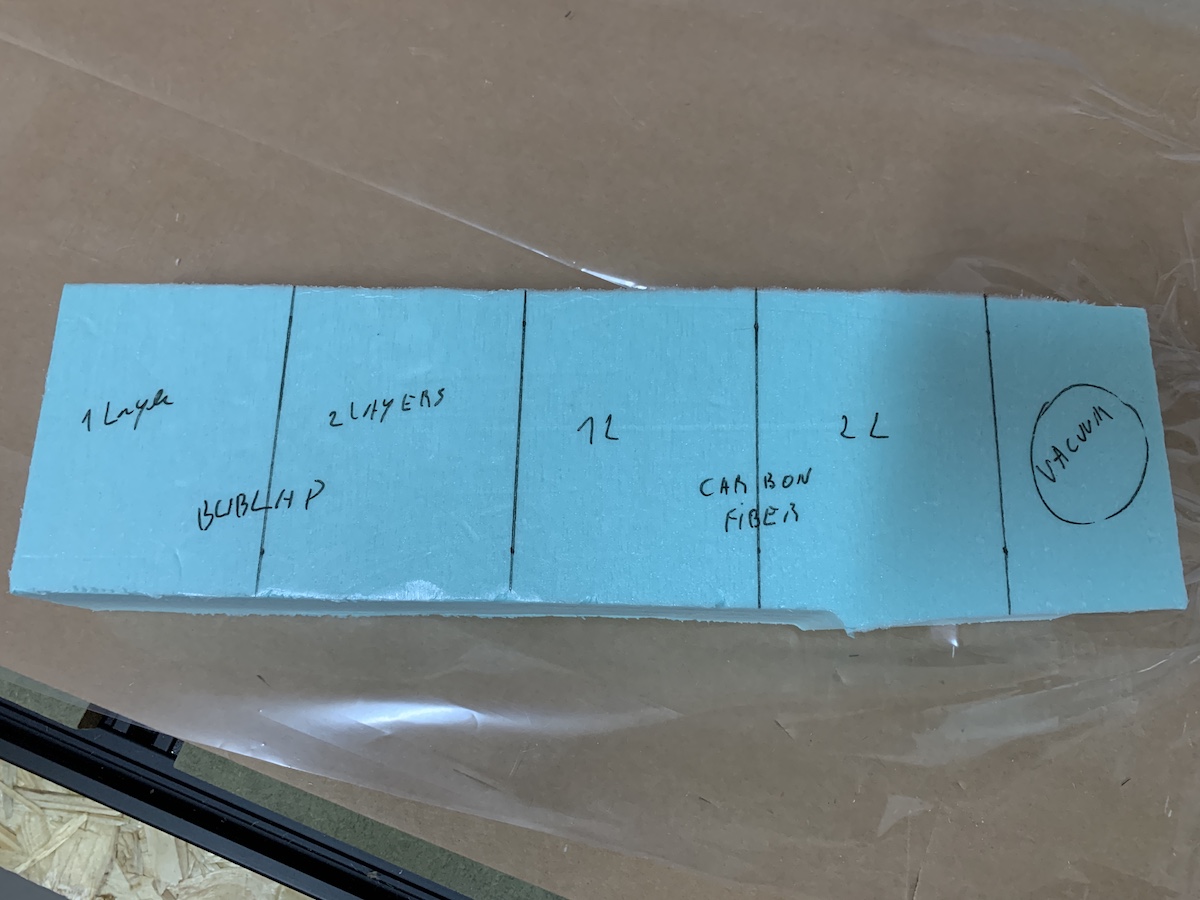
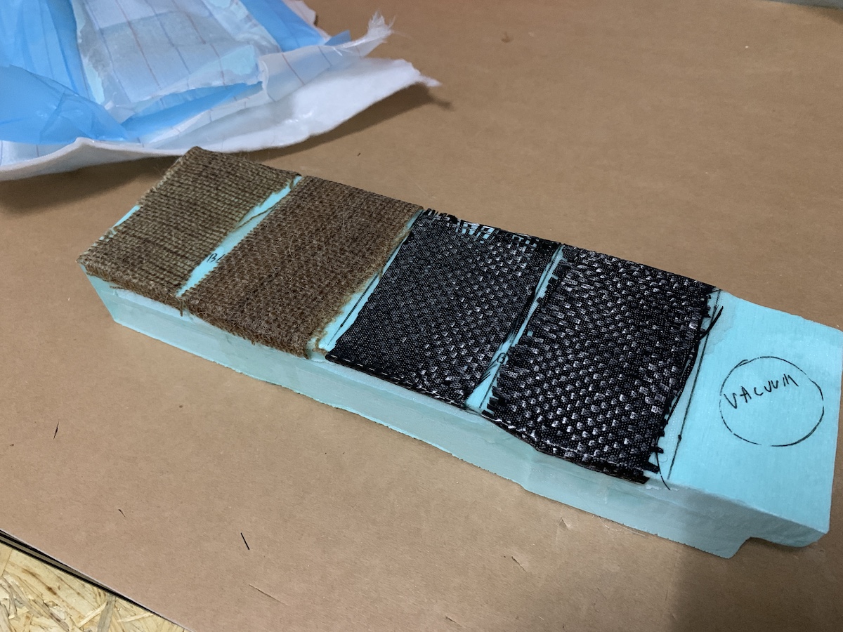
Before doing any composite work to make the car shell, decided to follow Neil’s advice and create some composite test coupons. This will allow to test the use of XPS with resin and the different fibers that i could use to create the shell.
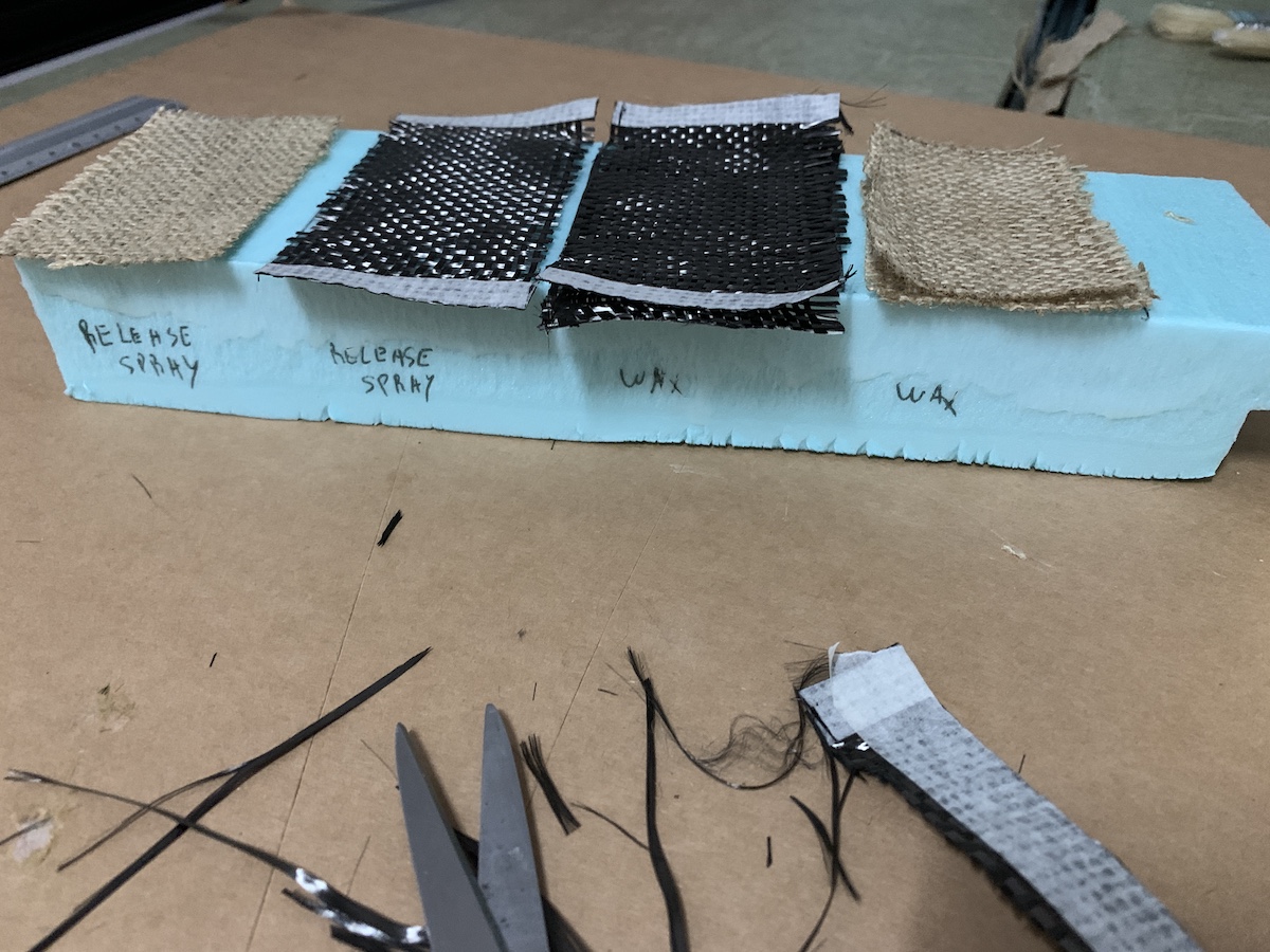
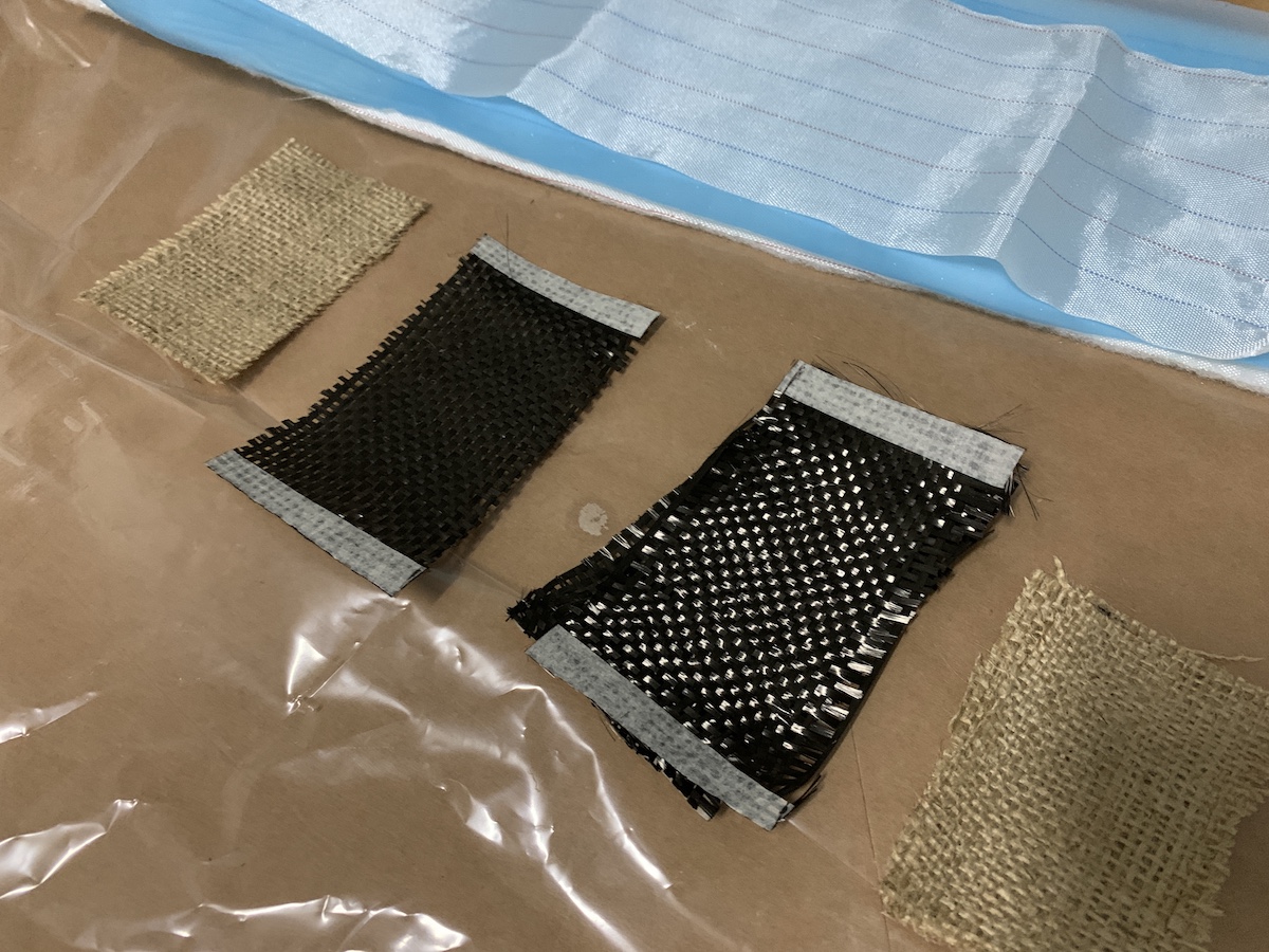
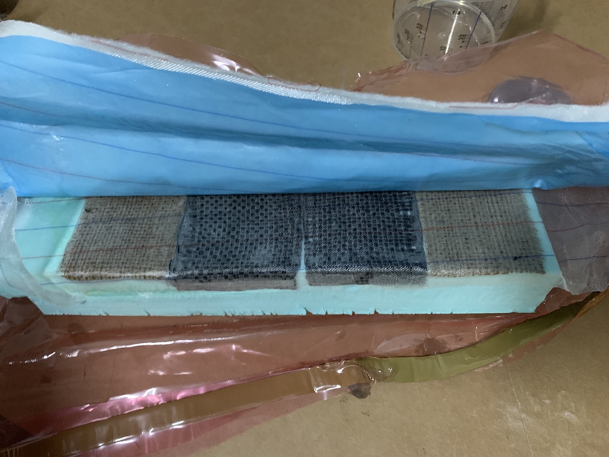
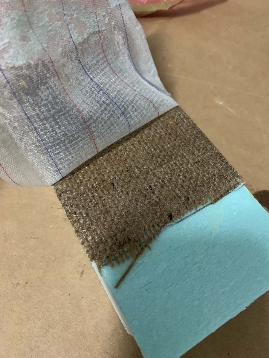
I’m using carbon fiber and burlap. Cut the 3 coupons of each material to test with 1 and 2 plies, on top of a small XPS block (as showed in the image below). Did also cut the peel ply, perforated film and breather layers a bit larger than the XPS block.
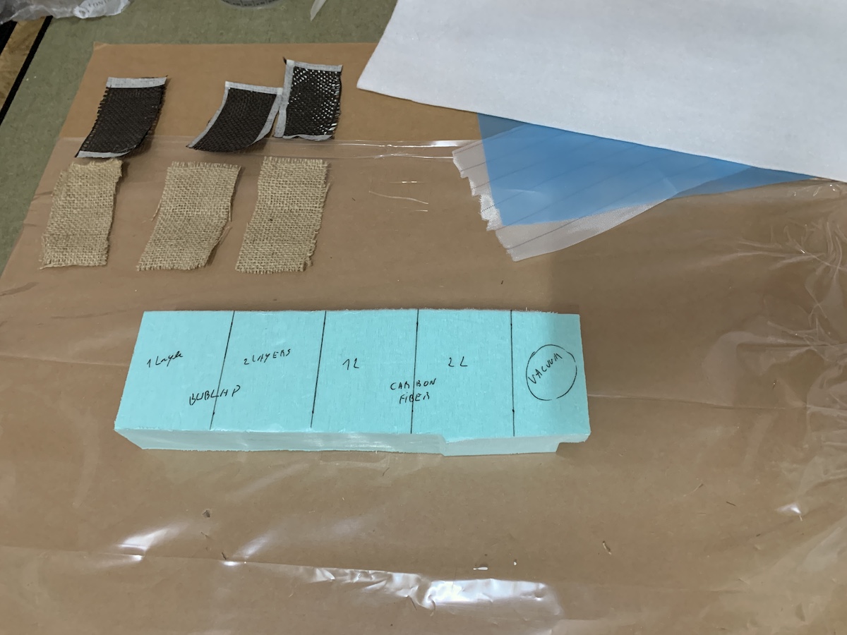
Cut the vacuum bag also a bit larger than the XPS block, then applied the mastic tape for sealing the vacuum bag on both sides.
For the resin, tried to mix total weight equivalent to the fiber weight to try to achive the 50% fiber and 50% matrix before the compression of the composite.
Each coupon has aproximately 8x6 (cm^2). To calculate the resin mix used the weight of the fibers as reference.
For this test mixed 13g of resin (Part A) with 7g of catalyst (Part B). Used a value of 2 in the weight multiplier just to be sure i had enough resin (even if there was some wasted in the mixing cup). In the table we can see that the burlap will need more resin than the carbon fiber.
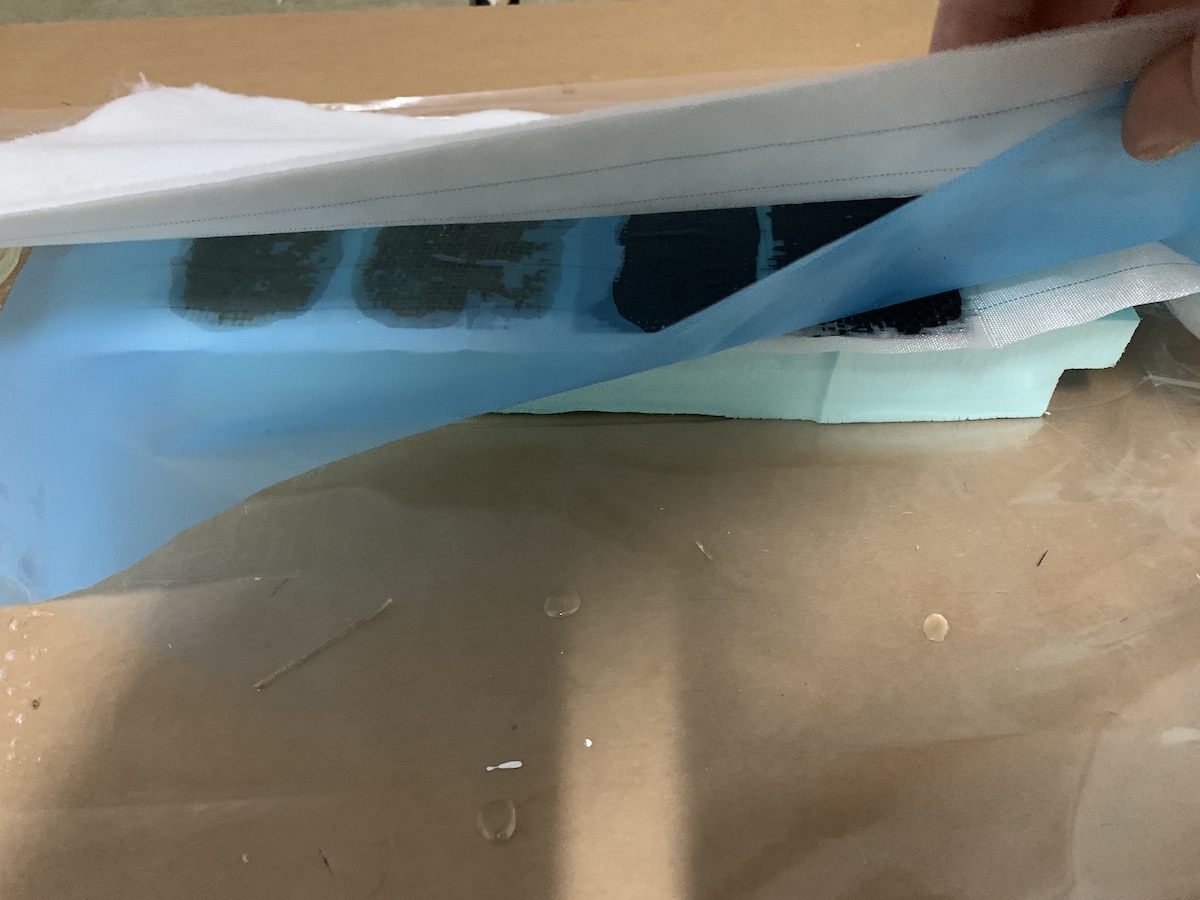
With the help of the wood mixing stick have applied the resin mix (matrix) in fibers and XPS. And layed the composite as described in the XPS (laminated plies with 2 layers) and 1 layers only for testing.
added the peel ply, perforated film and breather layers
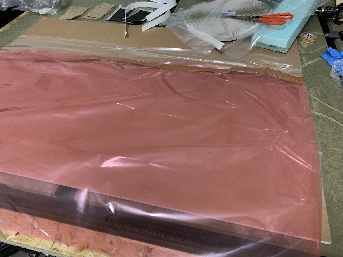
moved it into the vacuum bag and installed the vacuum connector
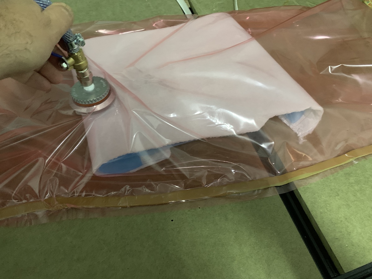
and turned on the vacuum pump…
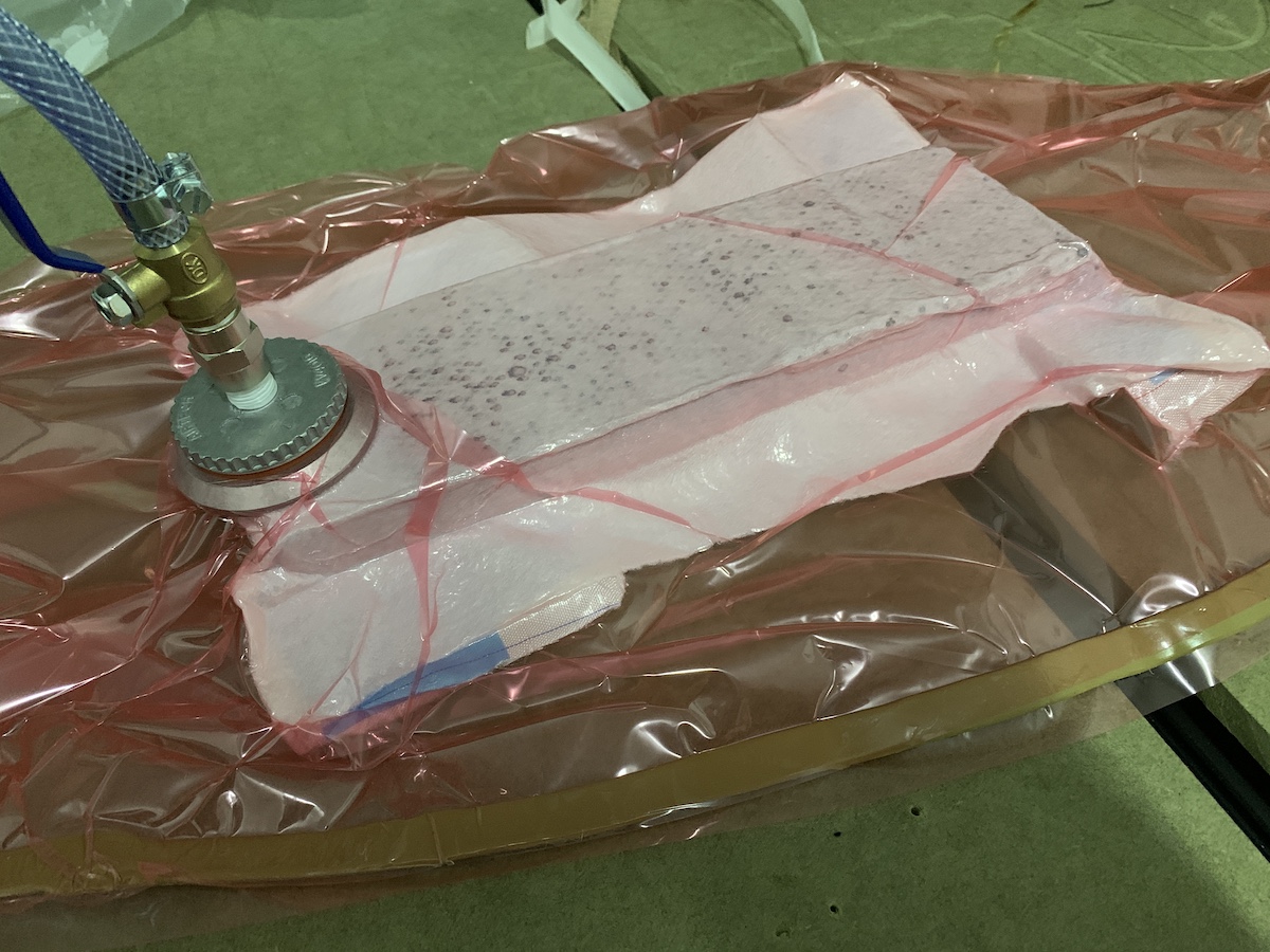
after some seconds the excess resin started to show into the breather material. All good up to this point. Actually, more or less :) the vacuum bag wasn’t 100% sealed, vacuum hooses needed to be properly fastened, so this test was… just a test :)
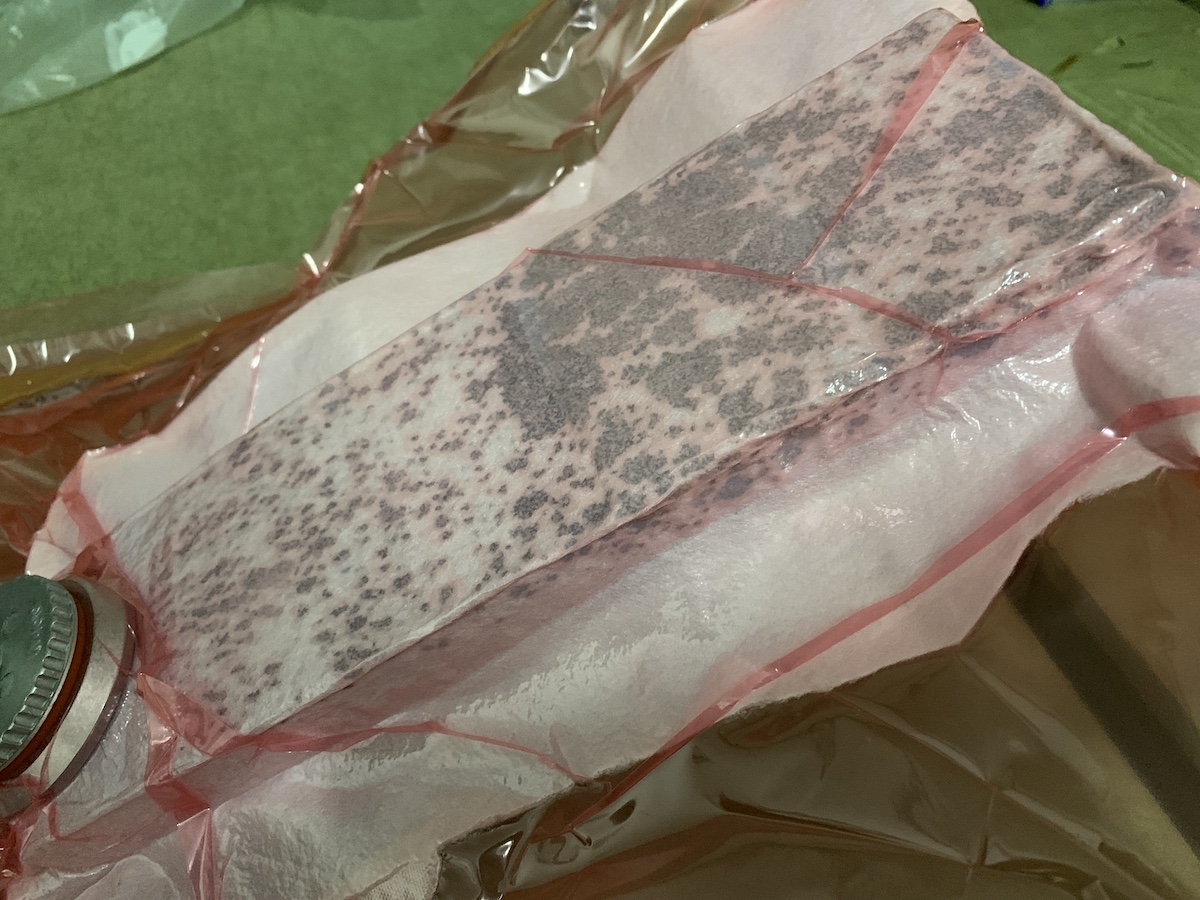
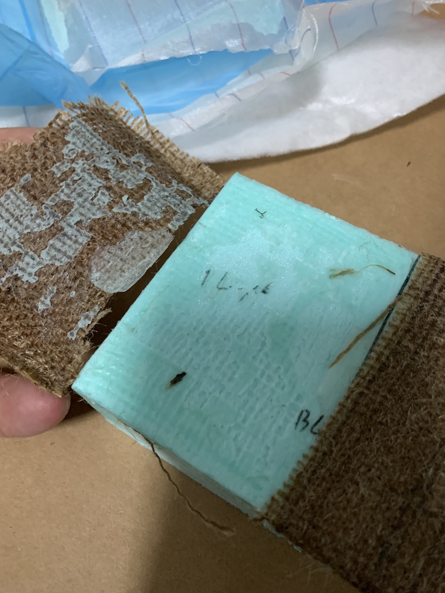
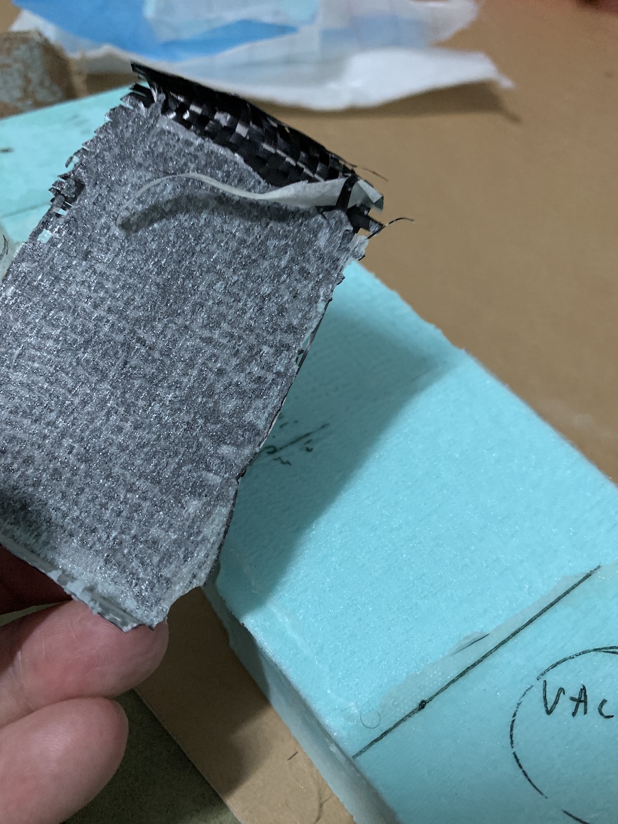
After some hours in vacuum and then waiting a day i checked how the resin had cured. Peel ply came off pretty easy, but noticed that the XPS foam was also glued to it.
At first glance this seams to be ok!
But wait… of course… the resin on glued to the XPS
So not the ideal result in terms of removing the composite from the mold/form. There is space here for improvements :D
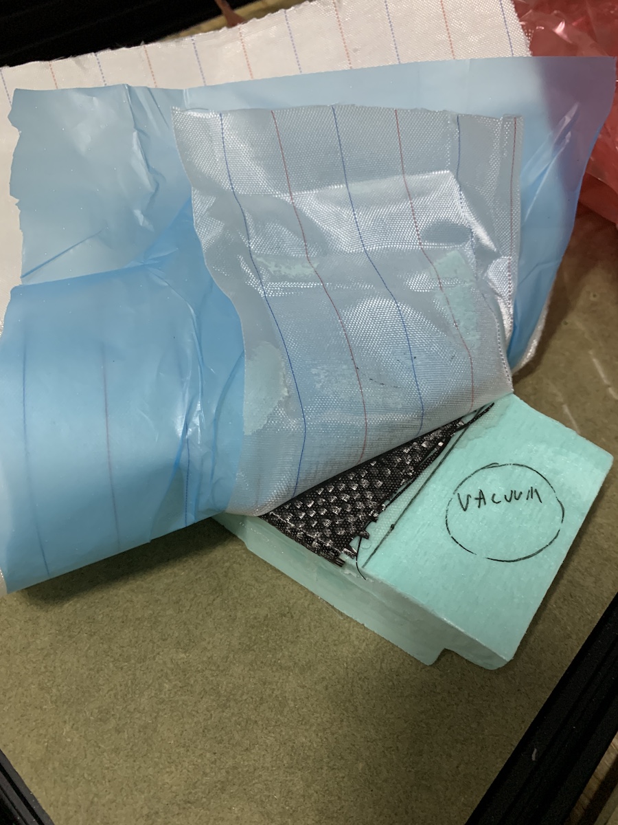
So after this “failure”/test, did another set of test coupons. This time i used wood glue on top of the XPS and release agents (spray and wax).
With the wood glue, there is a layers where i can apply and test the release agent.
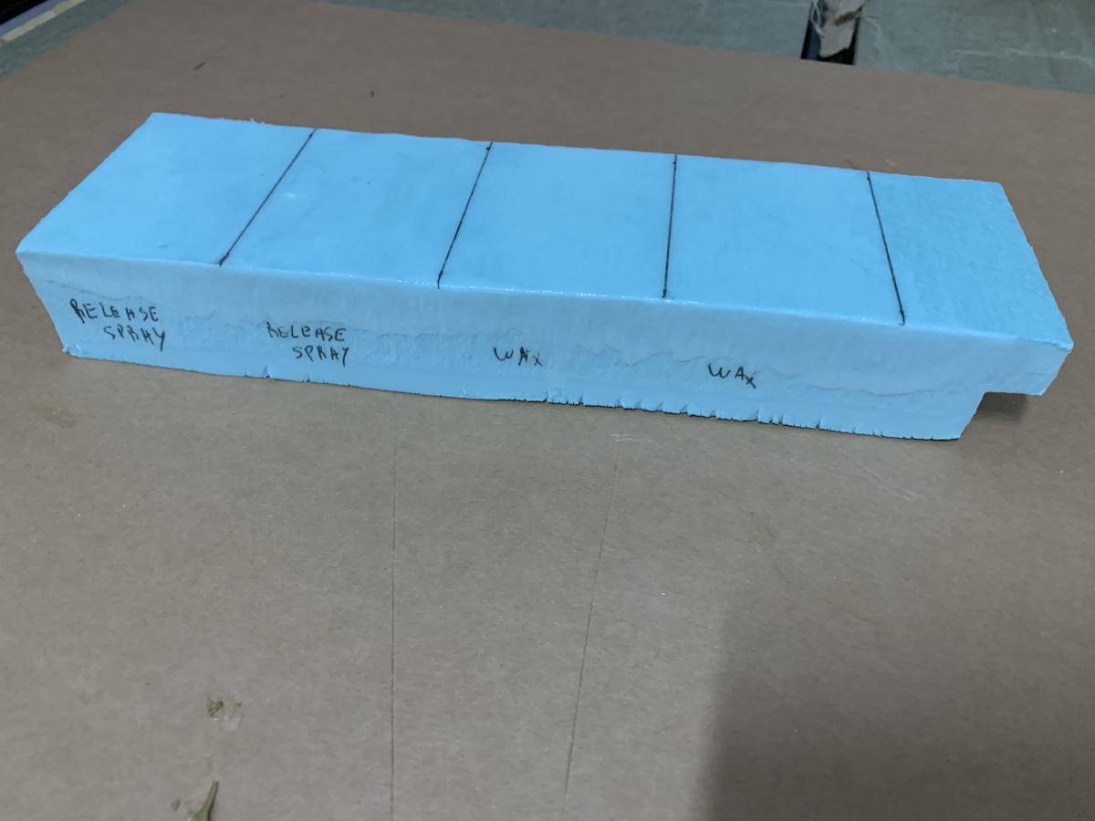
So preparing the new coupons, same drill as before to calculate the weight and mix for the matrix. Then applied the release agents (spray & wax) as described in the XPS labels.
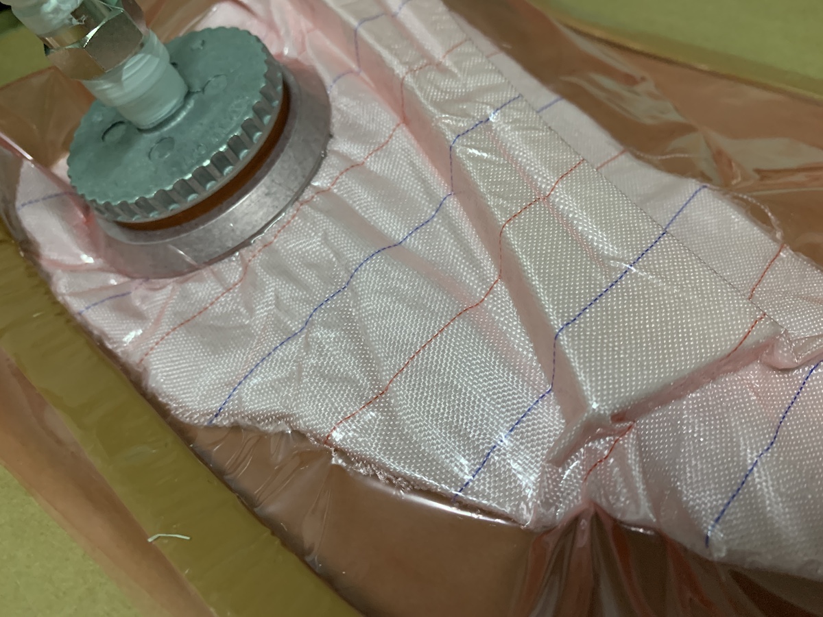
Have also taken time to properly create a sealed vacuum better. This is somethig that requires also some practice and patience. Used the previous mastic and small vacuum bag just to vacuum the breather material with wood inside to create the form. Took my time to seal the bag and then after turning the vacuum pump on, also took my time to check for possible holes. In the end, ended up with a properly sealed vacuum bag.
With the prepared coupons, cutted the peel ply, perforated film and breather material for this new test.
Made the new vacuum bag and applied the same resin mix to the fibers, followed same layer order as before and installed the vacuum connector.
Closed the vacuum bag and turned the vacuum pump on.
This was looking good, then waited some hours with vacuum ok and later turned it off. On the next day, checked how the resin cured.
The peel ply came off easily as expected.
Didn’t do any trimming, the coupons this time were ok. Uppon release they didn’t have any XPS glued to them, so the release agents worked fine between the wood glue applied to the XPS and the epoxy resin.
Making the car shell
Surface preparation
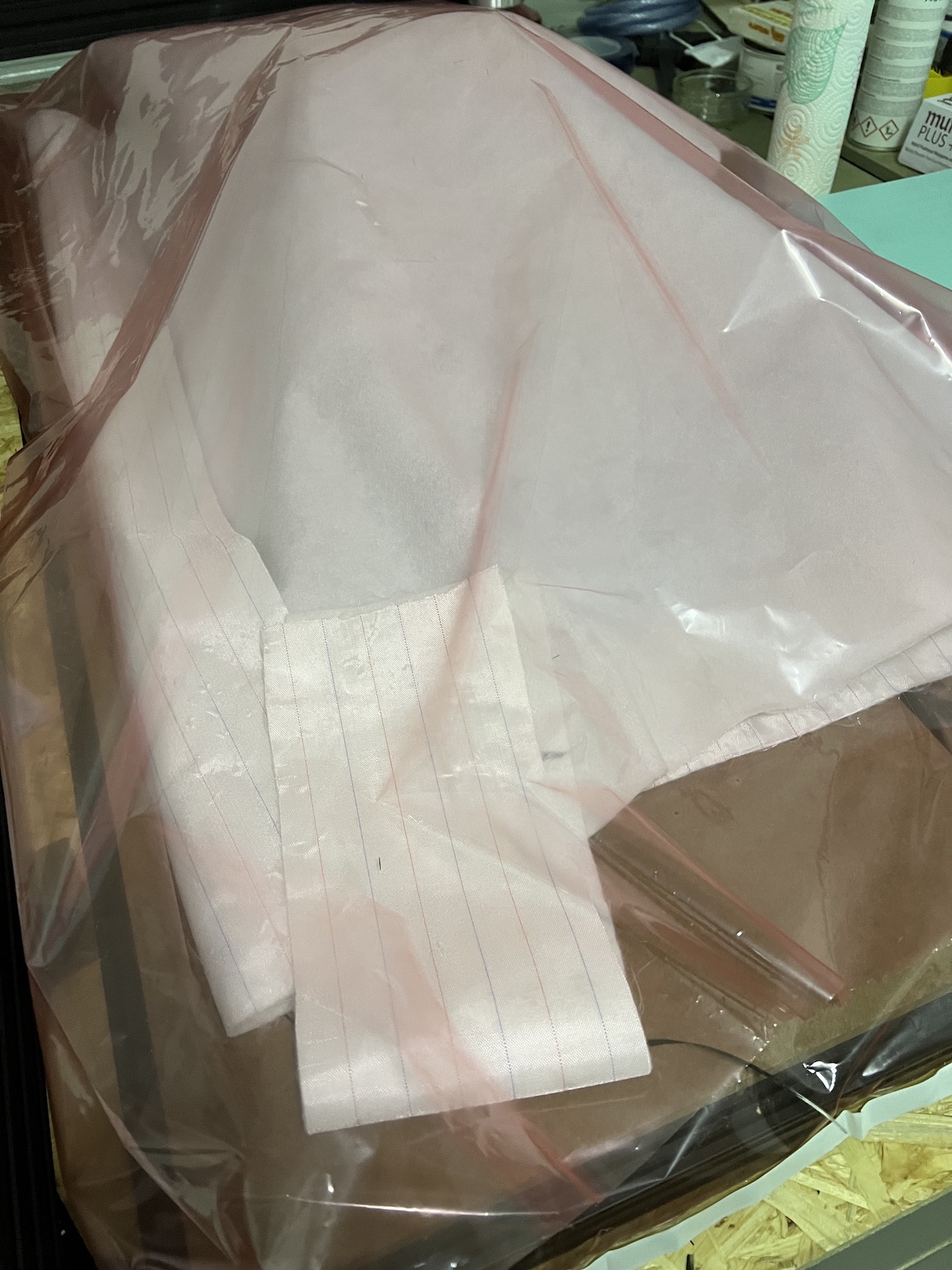
With the surface + or - cleaned i applied the release spray to the XPS so that the epoxy resin doesn’t glue much to it. Applied the spray, waited a bit and then repeated 2 more times. This way i have several layers of the release agent between resin and the XPS.
Composite
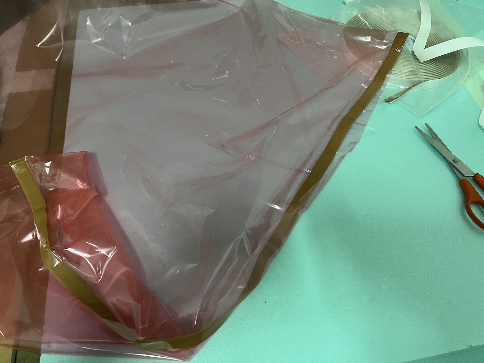
Now it’s time to prepare the vacuum bag, cut the fiber layers, peel ply, breather mesh, etc so that they can accomodate the car mold in length, width and height.
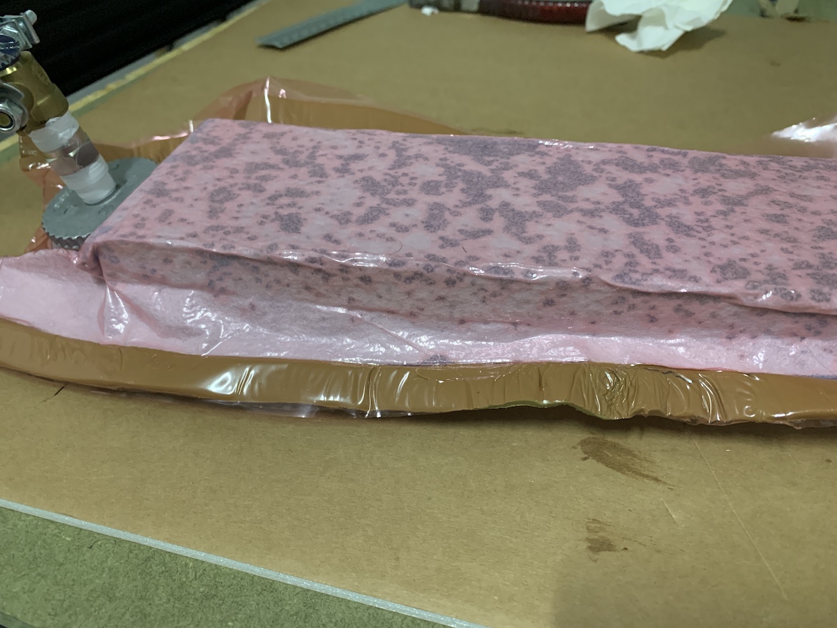
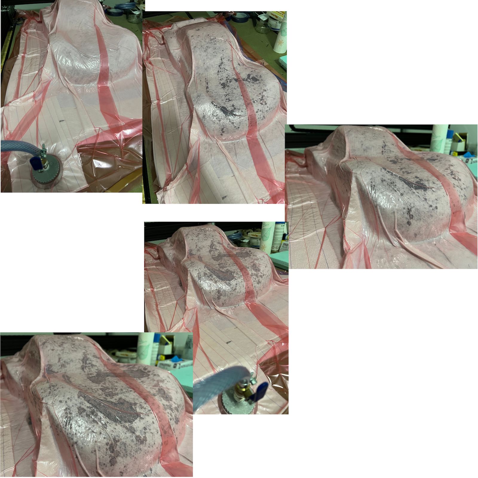
Cutted the vacuum bag with a length bigger than the car, peel ply, breather mesh accordingly for the top and bottom of the car. Then started to cover the car with carbon fiber
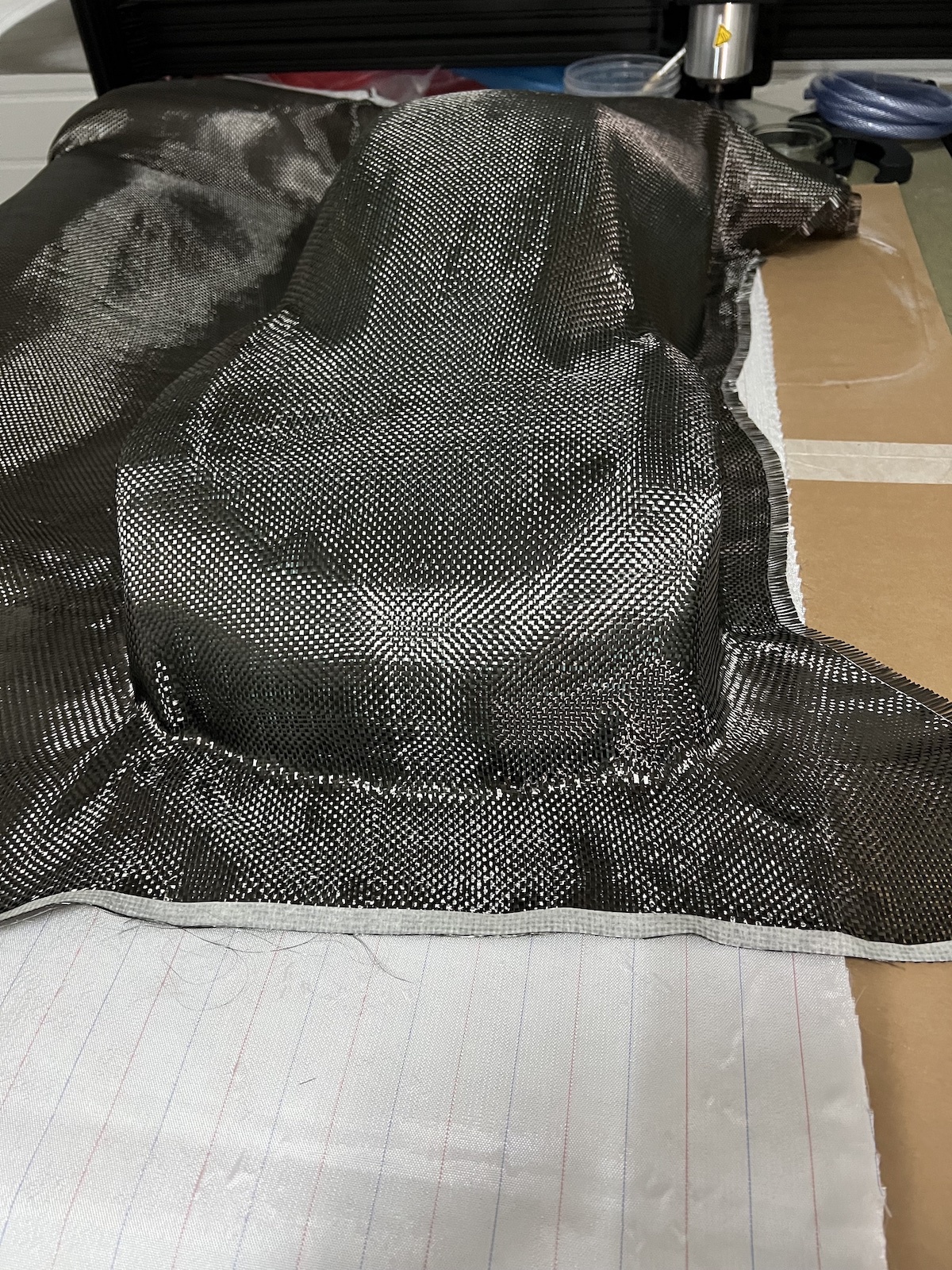
and cutting it around so that i could move slightly the cloth and adjust to the car
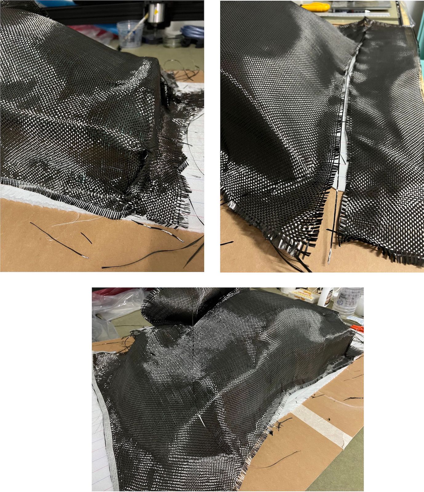
Prepared the seal of the vacuum bag with mastic
The vacuum bag is a big “tube” so i just need to seal it from 2 sides.
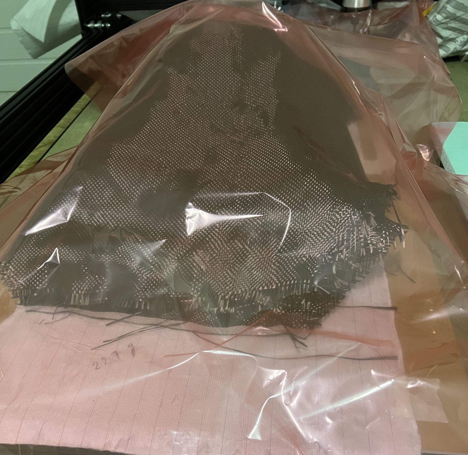
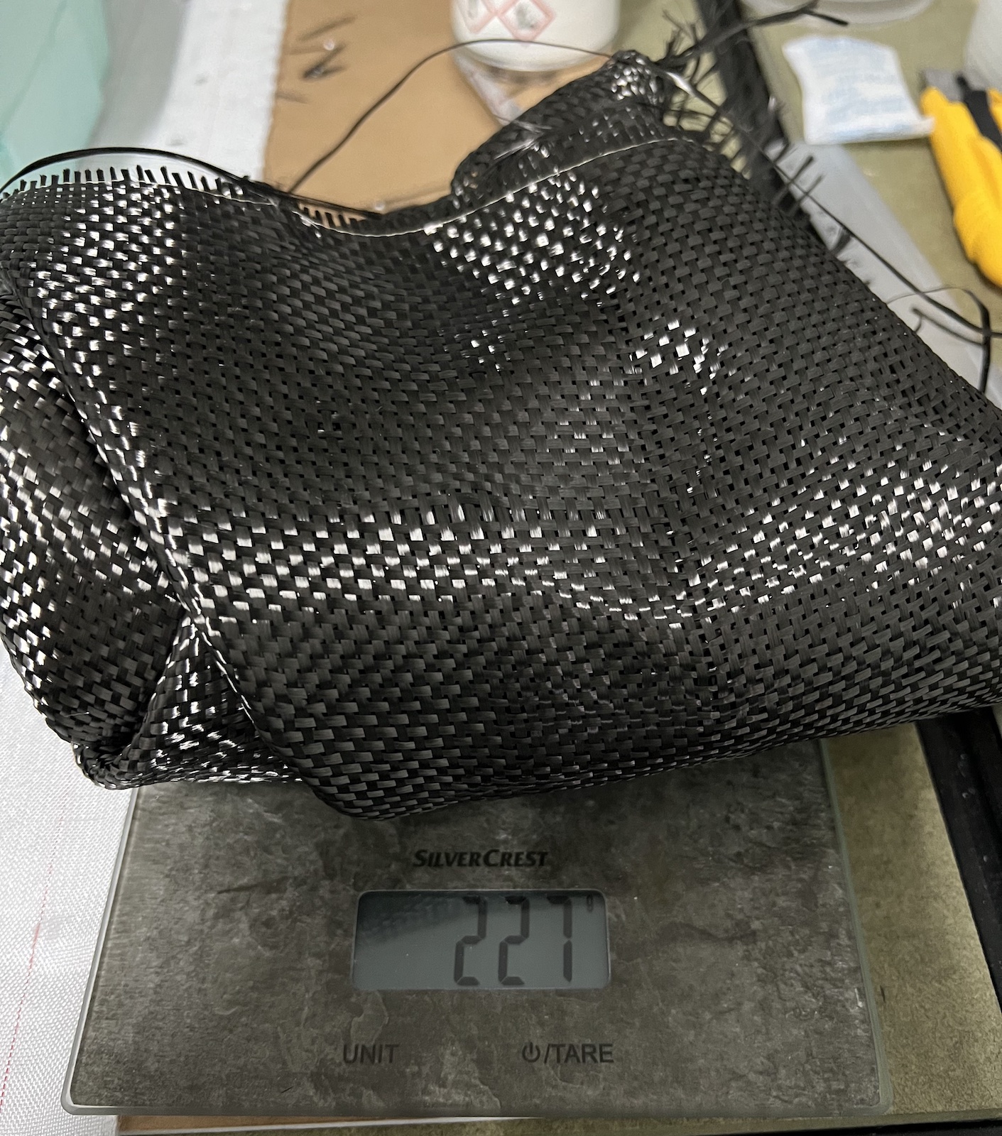
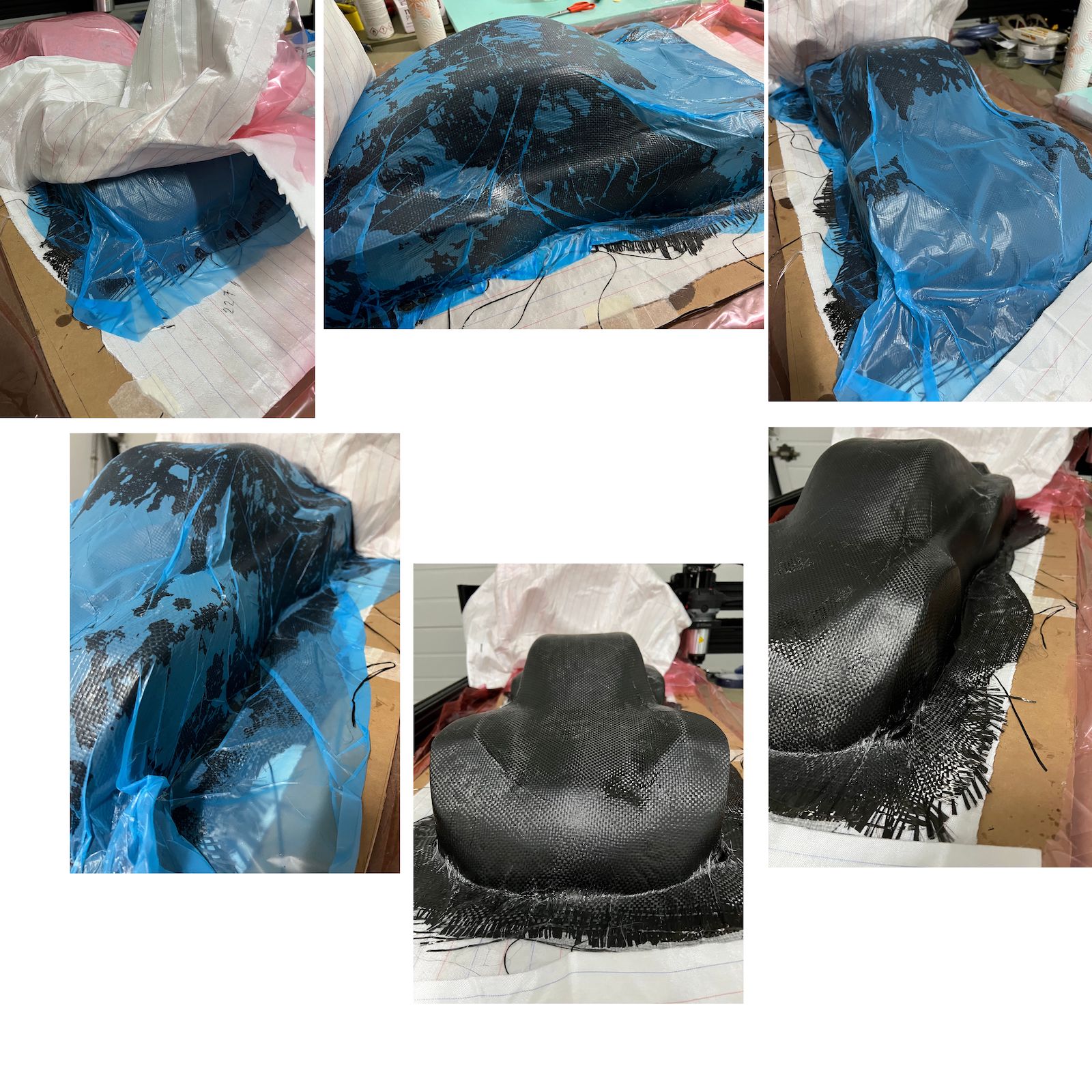
From the test coupons with 2 carbon fiber layers i think it was good enough to mold and create the car shell because it would be a bit flexible. But decided to go with 1 more layer, have cutted 3 carbon fiber layers for the wet lay-up.
Weighted the 3 carbon fiber layers
Then calculated the resin weight to empregnate the carbon fiber layers to make the composite:
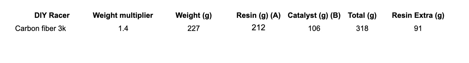
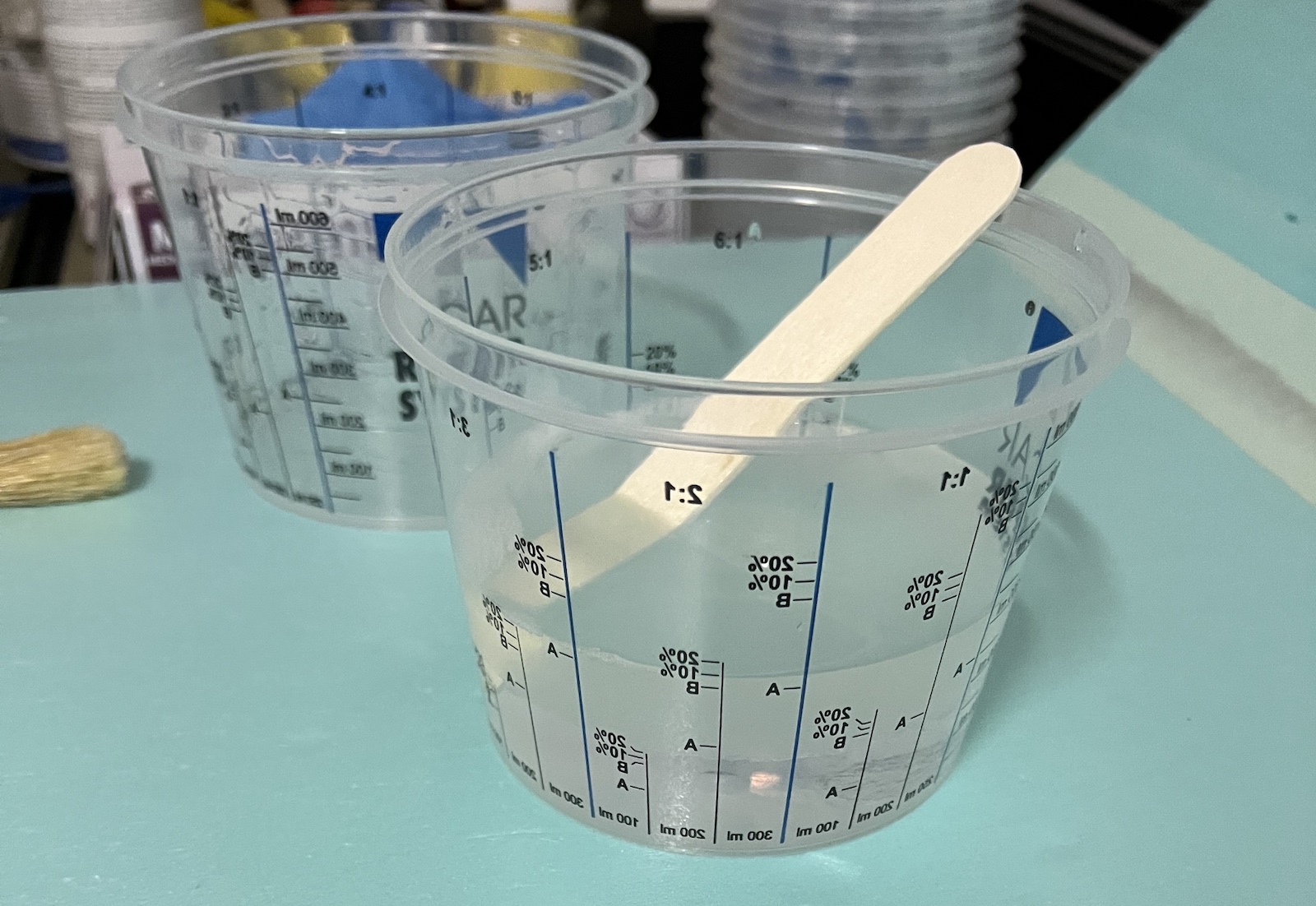
Mixed the resin (212g of componente A and 106g of component B)
Then started to apply the layers on top of the mold, with the help of a brush to impregnated the resin on each layer of carbon fibers added. Did this for the 3 layers of carbon fiber, adjusting the best i could the layers to the mold.
Then as tested before with coupons, applied the peel ply, breather mesh and small breather mesh folded in 2 so have the vacuum pump connector and allow to connect it to extract the air from everywhere inside the bag.
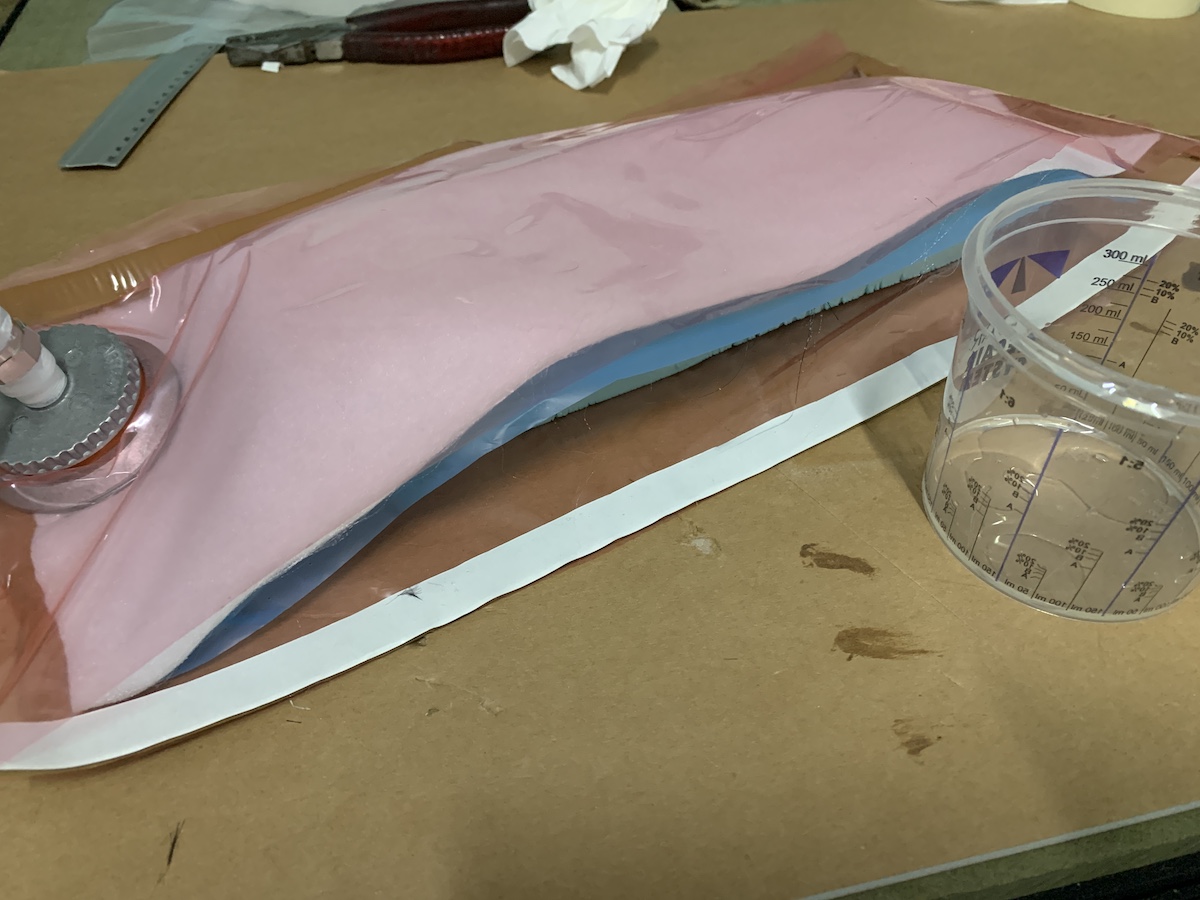
From this point added the vacuum connector and sealed the bag. Then turned the vacuum pump on. The photos below were taken some seconds apart, it shows the excess of resing being catched by the breathing mesh.
Final Result
After 2 days of curing (just to be sure :)) have unwrapped the composite.
Now i have some trimming work to do for the final project and decide how to connect the shell with the car chassis.
** “Hero Shot” **
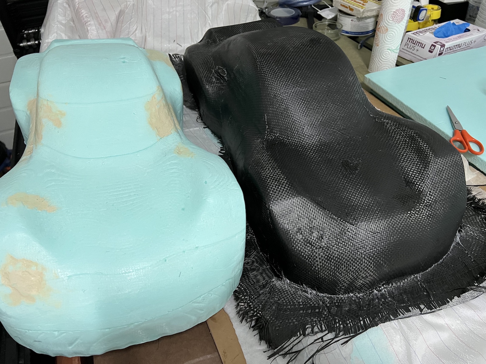
The result is good for my first experience with carbon fiber. There is room to improve and removing the shell from the mold wasn’t easy. Should have applied release agent also on the bottom of the mold, some excess resin got under and it was more tricky to separate the XPS on those points.
File: DIY Racer shell (Fusion 360)