3. Computer Aided design
For this week assessment the main objective is to testing 2D and 3D software to model (raster, vector, 2D, 3D, render, animate, simulate, …) a possible final project part. Document/showcase tested software with small step description and pictures.
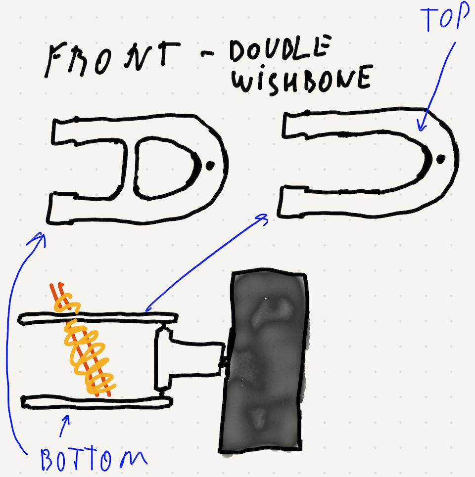
For this assignment tryied to model what could be an example of a RC car chassis and front double wishbone suspension for my final project.
Learning outcomes
- Evaluate and select 2D and 3D software
- Demonstrate and describe processes used in modelling with 2D and 3D software
Have you?
- Modelled experimental objects/part of a possible project in 2D and 3D software
- Shown how you did it with words/images/screenshots
- Included your original design files
2D
Raster graphics
Raster graphics are represented by a grid of pixels where each pixel has a representation of color. The size of the image is usually related with the number of pixels and to save a pixel you need a number of bits. These can vary according with different image file format. The images once drawn are usualy fixed in size and aspect.
For design mockups sketching i have been testing and using Paper App on Ipad. It’s a simple app that allows to draw images on ipad screen and export them as PNG format files.
Already knew GIMP, Photoshop and similar from the times i used Windows operating system and later Debian GNU/Linux. So decided to install Krita to learn and test-drive it.
Krita
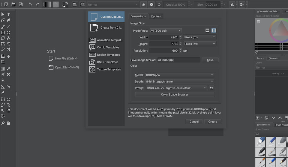
Creating a new file
And after drawing some lines, rectangles, filling in some white spaces and cutting i got to a krita draw of the same front suspension part.
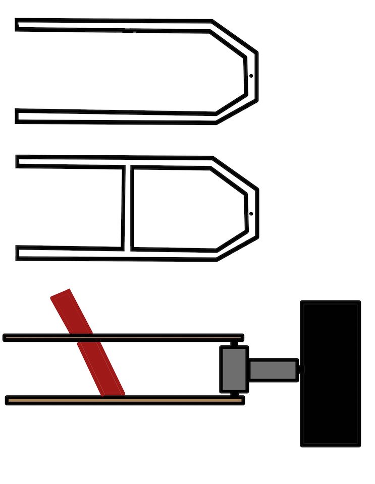
File: Krita krita_front_suspension.jpg
Note: Using ImageMagick to convert images from PNG image into JPG image format.
mogrify -format jpg *.png
Please check Download ImageMagick to install ImageMagick on your system. In my case i installed via Homebrew.
brew install imagemagick
Links
Vector Graphics
Vector Graphics are different from Raster because of how the drawing information is saved and used. So for each draw it saves 2D points which can be connected by lines or curves to form a shape. These can then be scaled or zoomed without loosing detail because the x,y points can be updated and redraw. While for raster pixels if you zoom in you will see pixels or scaling will loose image quality because pixels need to be added manually or via an algorithm.
So from the class list of software there were some i already knew like Inkscape, Illustrator, CorelDRAW and Scribus. Then decided that from the rest of the list i would re-install Inkscape and FreeCAD to learn and test-drive them.
Inkscape
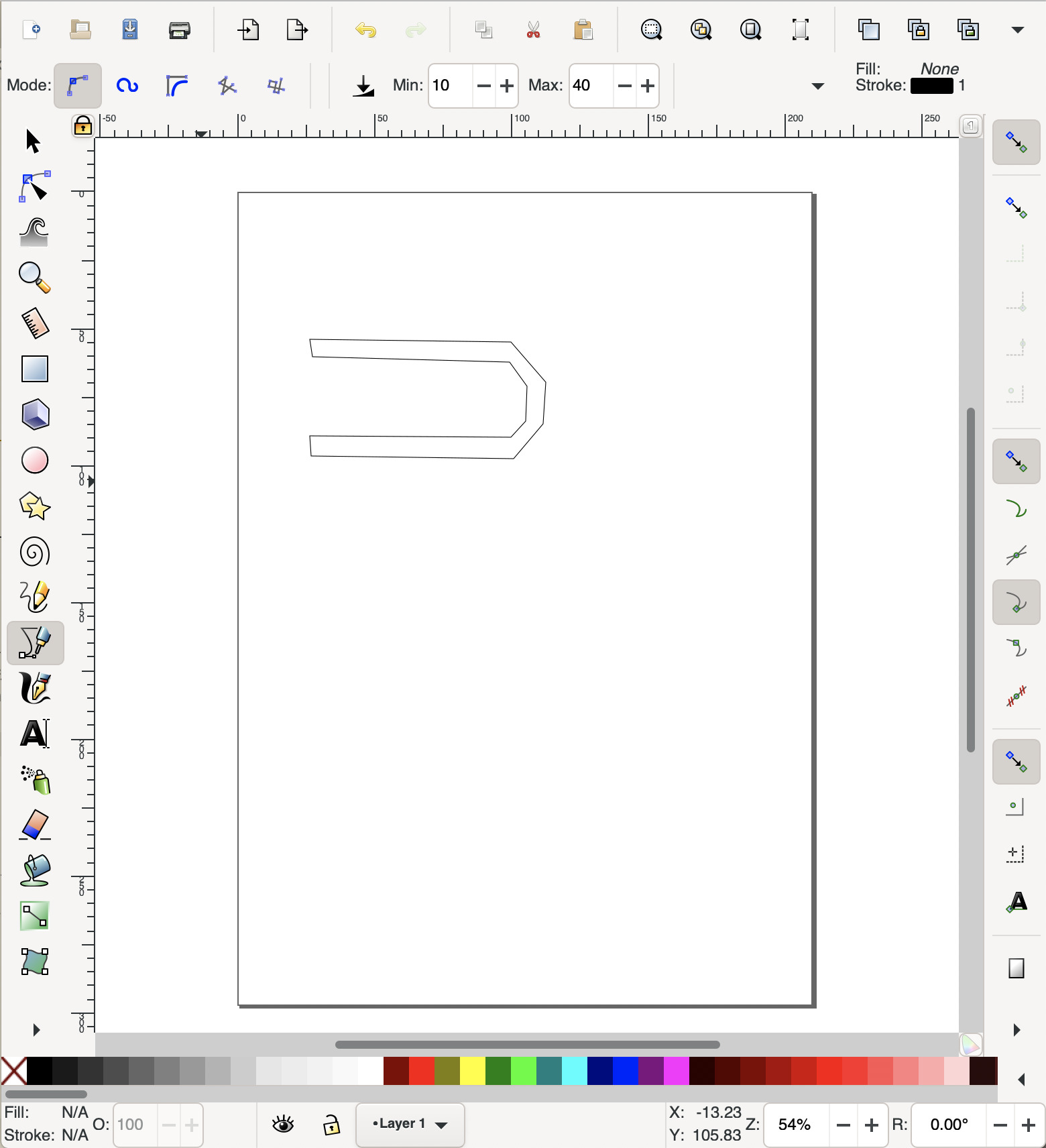
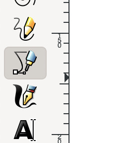
To make the draw used the Circle tool for black dots. Bezier curves and straight lines tool to make the suspension wishbones.
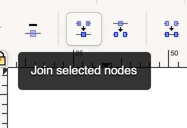
And learned how to Join Selected nodes to join/combine path.
These are the same double wishbone suspension parts, draw in vector and saved in SVG. If you resize the page the drawing will resize.

File: Inkscape front-suspension.svg
Links
3D
For 3D modeling i already know basics of Sketchup and OnShape so from the list of class programs choose FreeCad and Fusion 360 to learn and test-drive them and eventually also Blender.
FreeCad
FreeCad is a 3D CAD/CAE multi-platform open source software with features like parametric modeling, Open CASCADE Technology, geometry-constrained 2D shapes, simulation, Building Information Modeling (BIM), etc.
So in FreeCad object design is based on sketches. Then we can constrain those sketches with simetric constraints, size constraints, etc. To learn FreeCad i choose to do the FreeCad Lesson 01 on how to model a Turner’s cube.
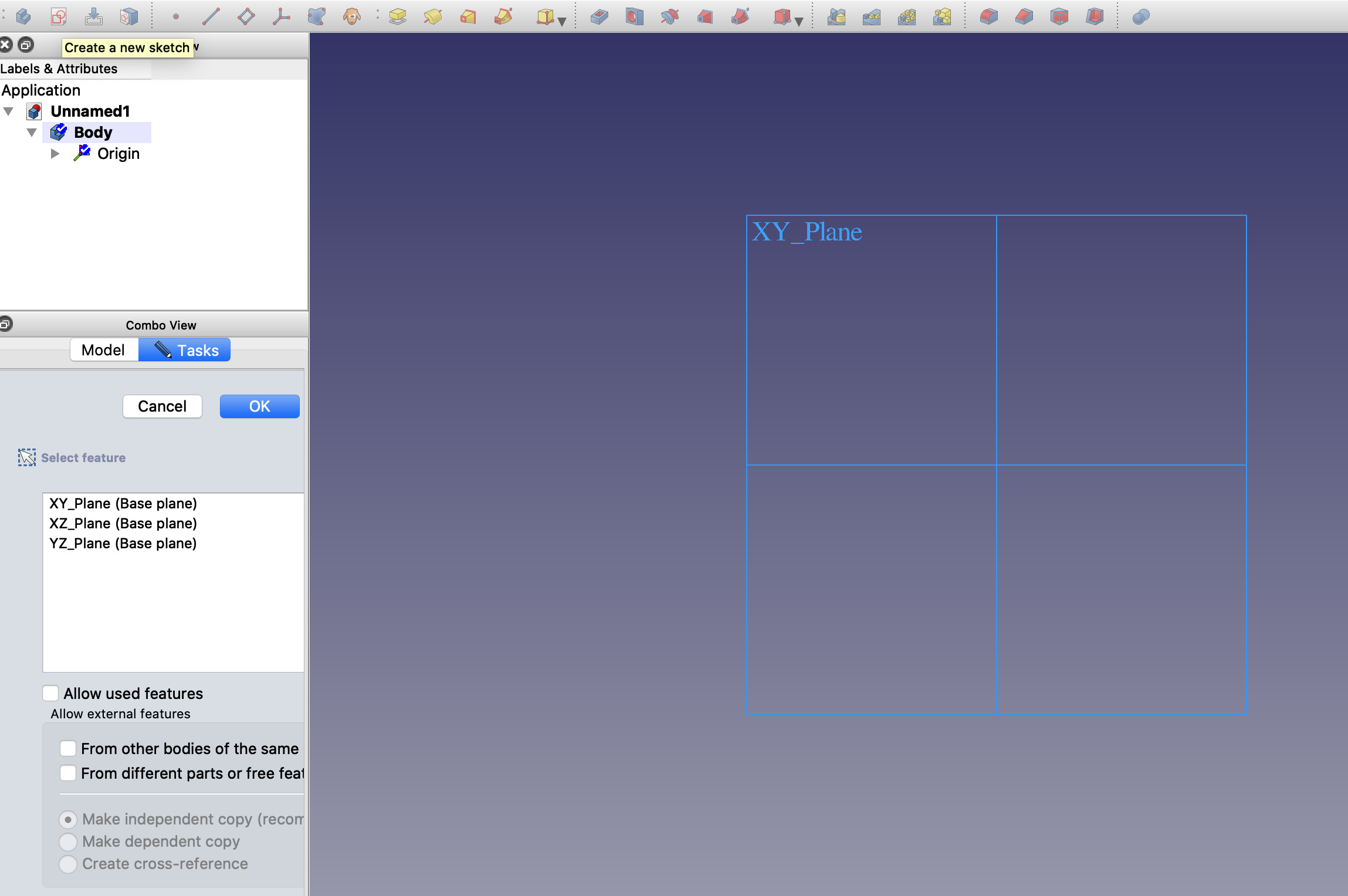
First started by creating a new document, then selecting “Part Design” and create a sketch on XY Plane.
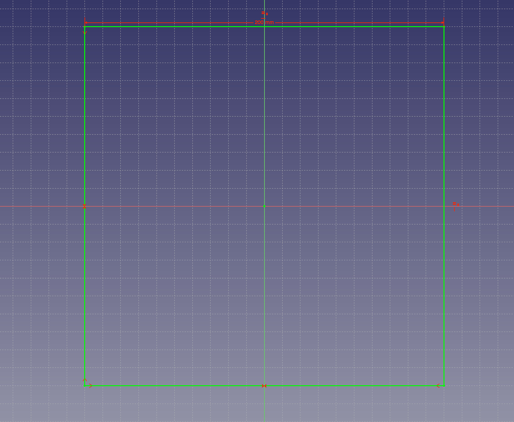
Next step, create a rectangular sketch using  and constrain it so that it is centered, fixed width and all sides are equal (with 0 degrees of feedom)
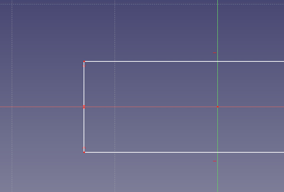
For example selecting top-left point, bottom-left point and x-axis (points and axis in green).
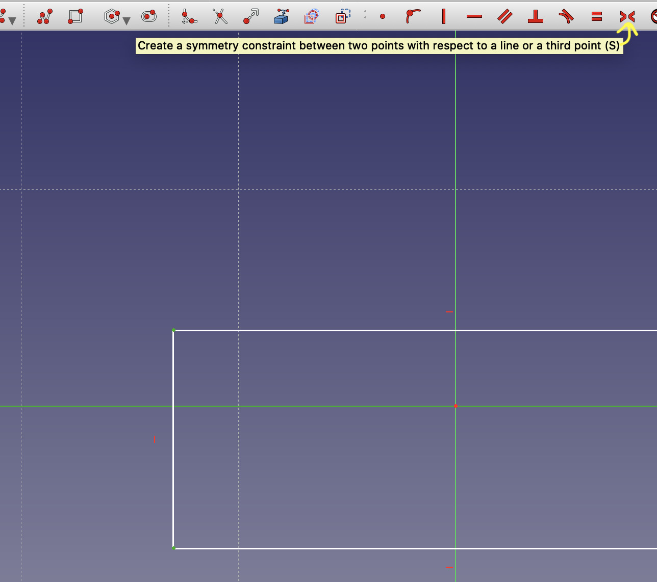
And creating symmetry constrain to have points at same distance of x-axis (applied constrains in red)
After applying all constrains have a square of 200mm width.
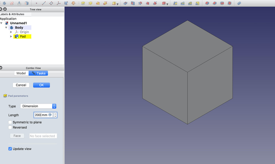
At this point sketch is closed and used the 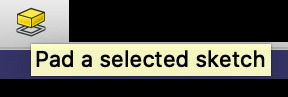 to create a cube with 200mm height.
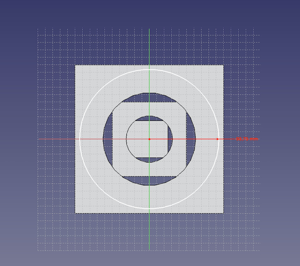
Once the cube is ready, clicked one face to select it and clicked on new sketch to start drawing the circle used to remove material from inside the cube.
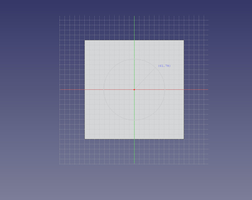
Applying circle constraint 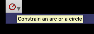
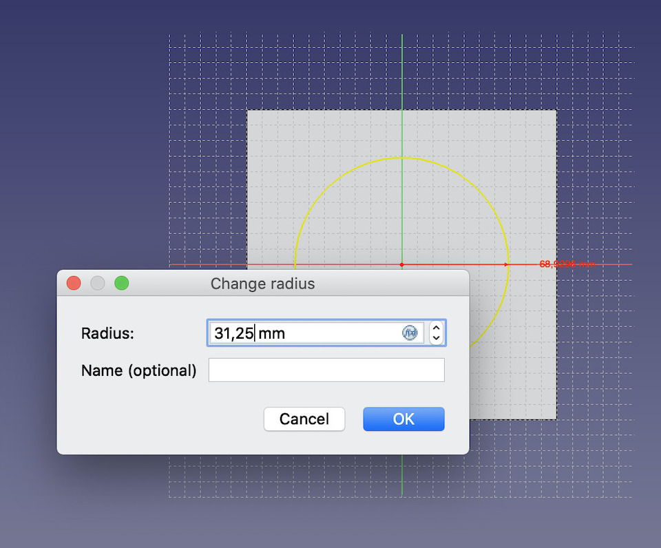
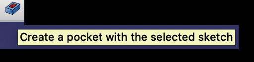
Close sketch and click . Set pocket dimension to 75mm to remove circle material.
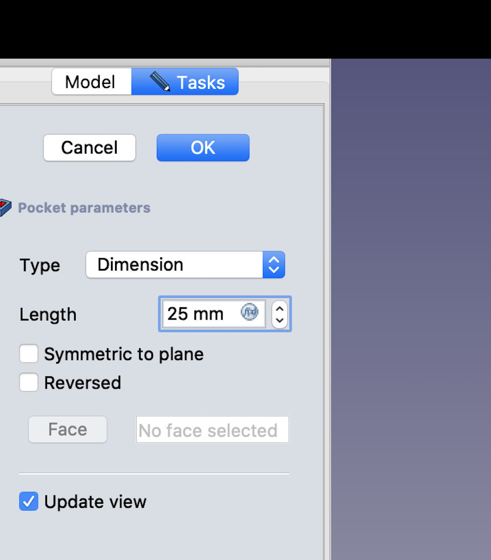
Then this process repeats by adding 2 more circles (62,50mm and 93,75mm) and pockets (50mm and 25mm) on same cube face and exact same process repeats for all faces .
Until you reach the final result.
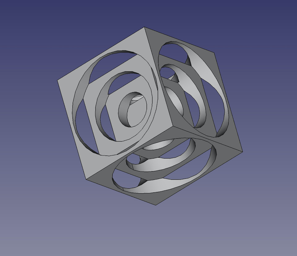
Besides the symmetry, equal constraints also tested the coincident contraint that allows to align sketches by selecting 2 points to be on same point.
File: FreeCAD freecad_cube.FCStd
You can view, rotate and zoom the WebGL object in the picture below. Exported from FreeCad in WebGL file format, then moved js code into ‘docs/javascripts/turners_cube.js’ file to work on the page. Powered by three.js by adding extra_javascript libraries into mkdocs.ml.
Fusion 360
Fusion is a very well integrated 3D design software. It allows to design, create 2d/3d models, design electronic pcb, in a more or less easy interface that allows for fast prototyping/product development. It also allows to simulate and create parts with Generative Design.
This is a new software for me so i’m learning the basics. Drawing in a plane, extruding, rounding corners, parametric design, etc.
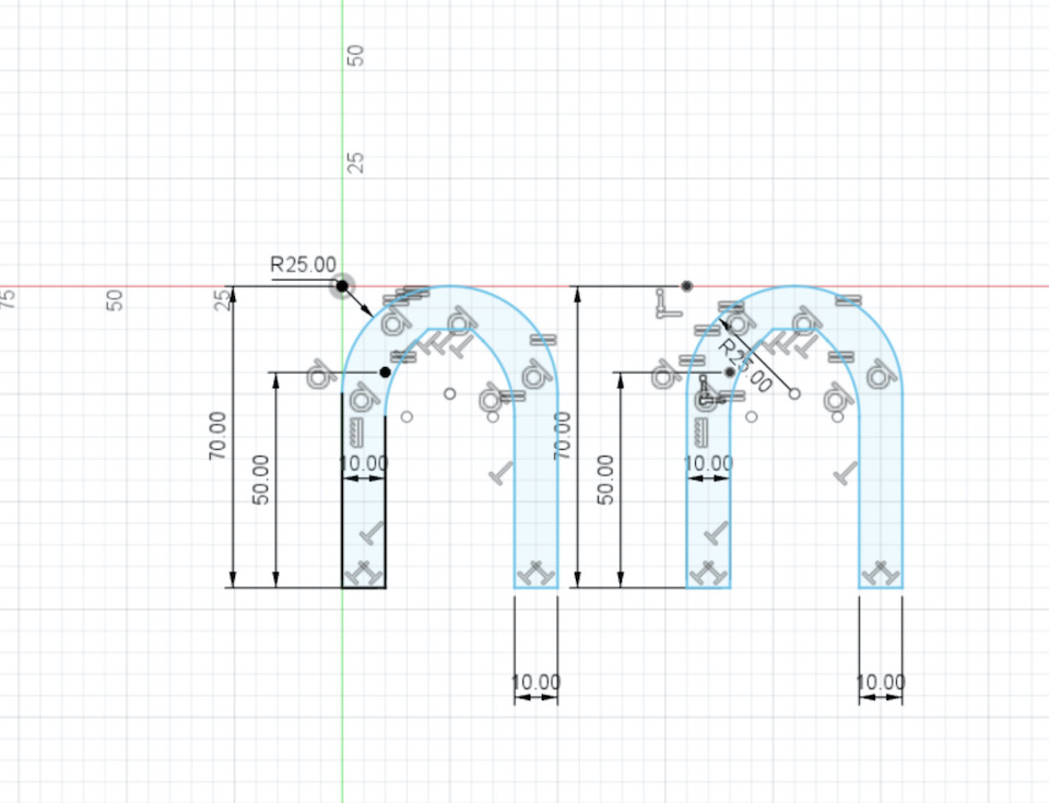
So to test drive Fusion i started by drawing the outline of the suspension wishbone, with some measures in mm.
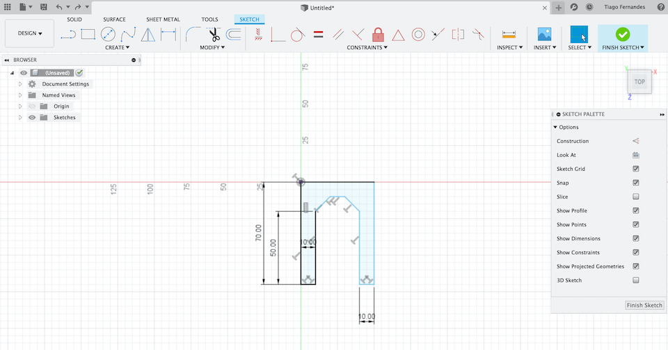
Then made a copy
After adding the lower whishbone shock absorber mount points, selected the 2 objects.
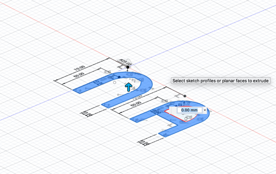
And extruded 5mm, by right-button mouse click and “Extrude”.
Then i tested “Fillet”
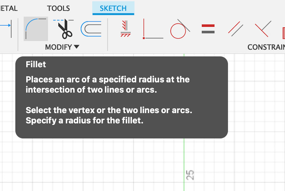
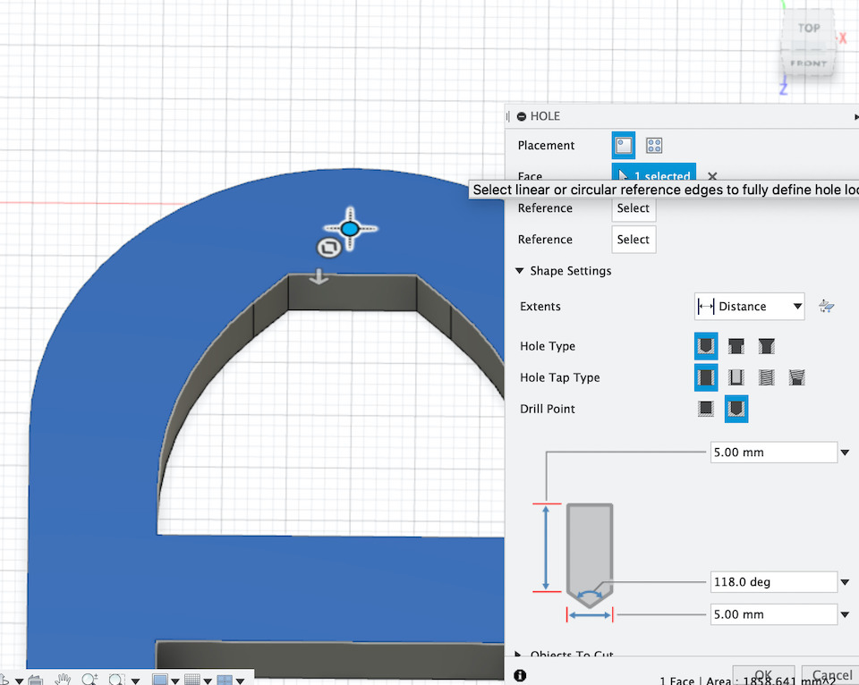
and the create “Hole” tools.
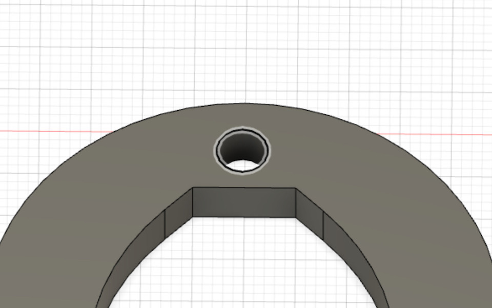
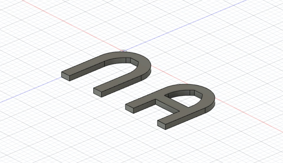
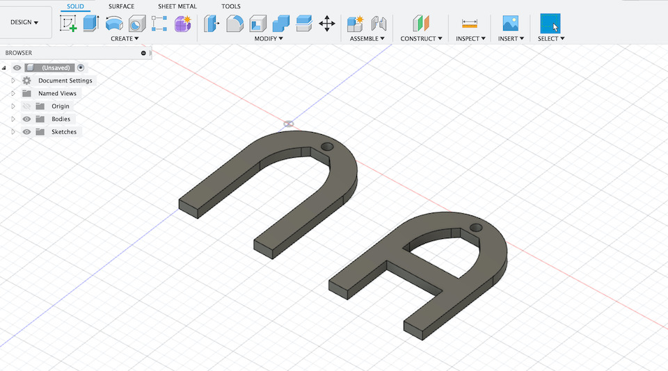
In the end i manage to draw the uppper and lower suspension wishbones.
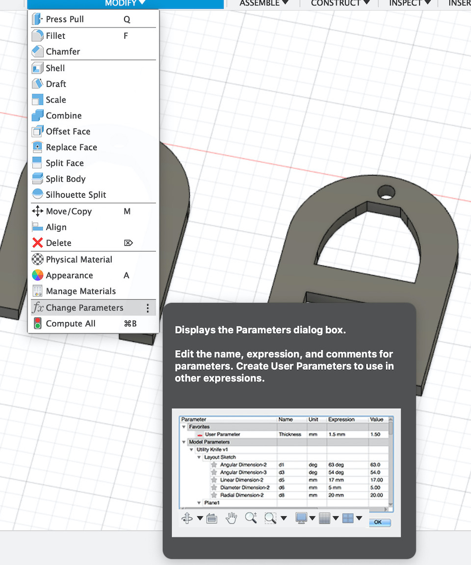
Have also experimented the parameters change after having made the objects.
So from 5mm material height
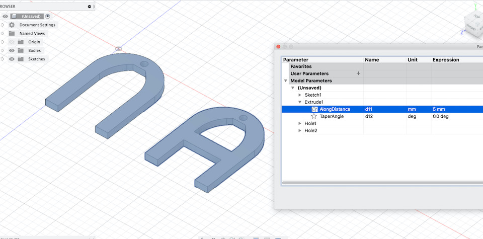
I have changed “AlongDistance” attribute to 10mm, for testing, and the model was updated accordingly.
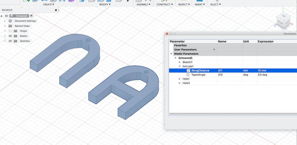
The parameters can also be created and used instead of values while we are making the model. This makes also easy to dynamically update model size in several places at same time.
File: Fuion 360 front_suspension_v1.f3d
This is just the beginning, Fusion has a lot, lot more to explore!
Fusion Challenge
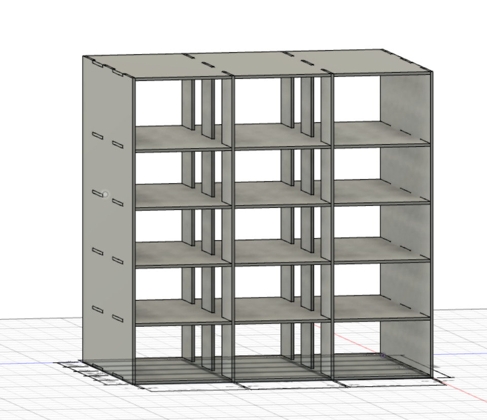
We were challenged by our Mentor to learn Fusion while building a drawer organizer module and then to design a hot glue stand. The objective was to improve the skills and learn Fusion by example and practice while exploring parametric design and parameters/variables use (like tickness, contraints (fx) that use other measures to keep distance,etc).
You can check the results in the images below.
Design a drawer organizer module
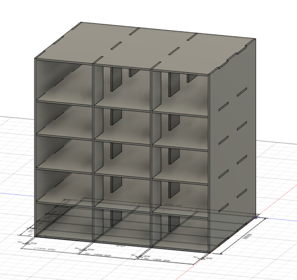
File: Fusion 360 organizer_module.f3d
Design a hot glue stand
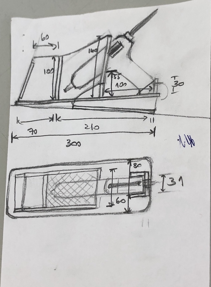
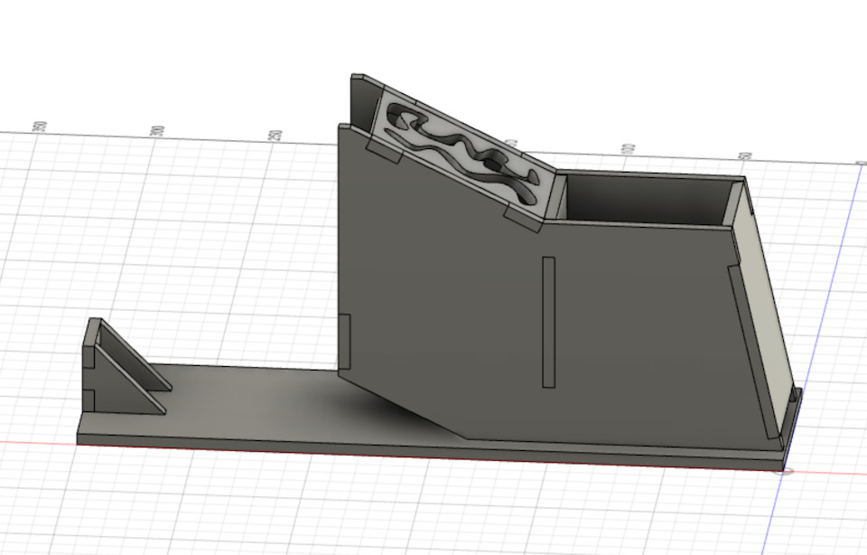
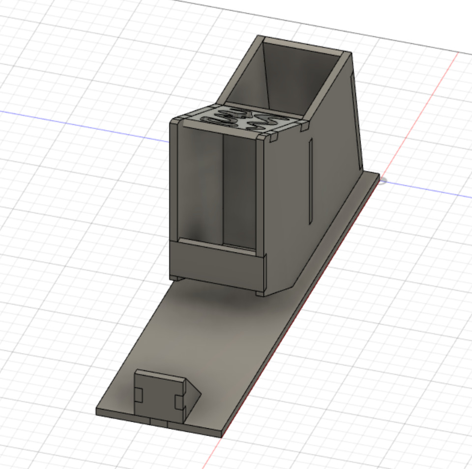
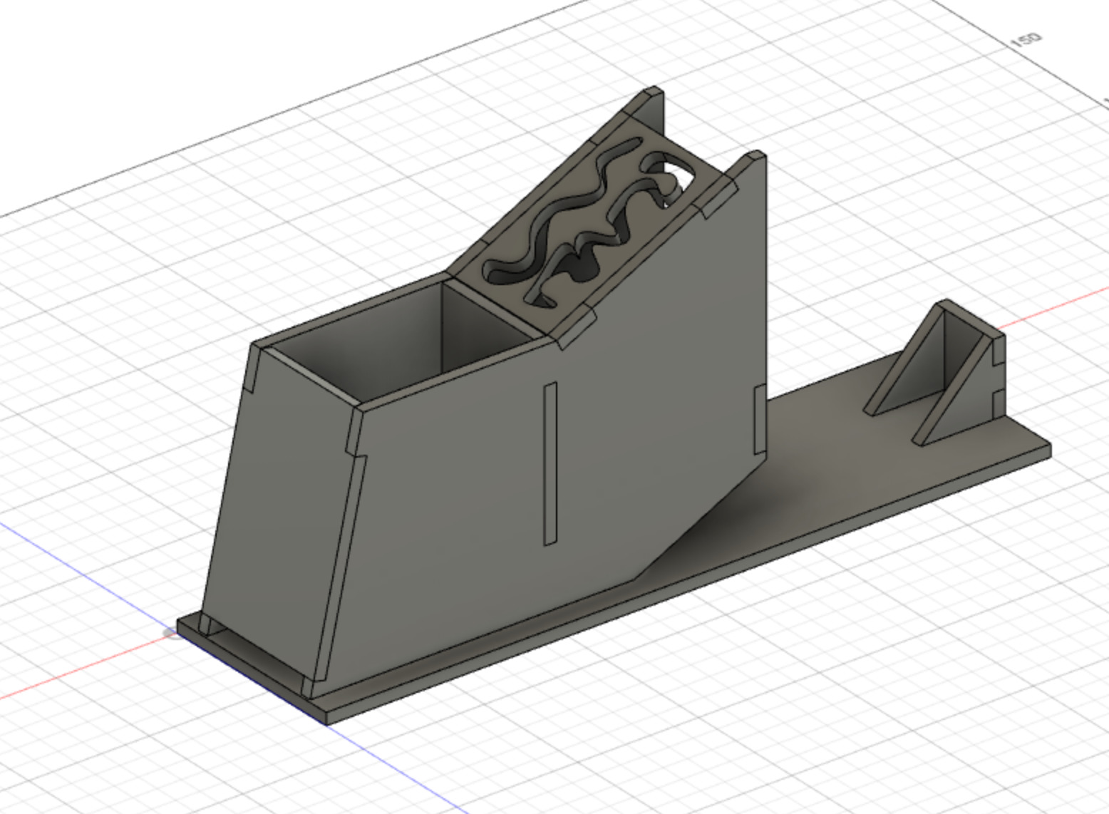
File: Fusio 360 hot_glue_stand.f3d
Blender
In Blender objects are represented by a polyghon mesh. This mesh consists in a collection of vertices, edges and faces, defining the shape of a polyhedral object.
For this i only checked the tutorial and learned basic model and how to move along the interface. Didn’t do much while exploring, didn’t find it intuitive to use, requires a bit more exploration and time.
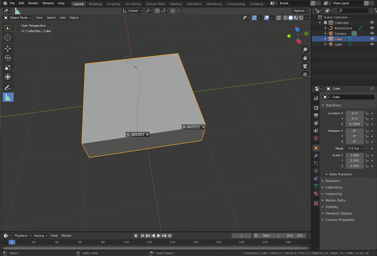
File: testing.blend
Links
- FreeCad
- FreeCad Getting started
- FreeCad Lessons for Beginners
- Fusion 360
- Fusion 360 - Designing a Lasercut Laptop Stand
- Parametric Designs - Using Variables in Fusion 360
- Blender
- Blender 2.81 Reference Manual
- Blender tutorials
- Blender Fundamentals 2.8
Learning outcomes
This assignment helped to test some of the 2D and 3D software. Some i already knew like GIMP, Inkscape, Fusion also but didn’t work much with it. In the end the assignment helped to decide and select which 2D and 3D software to use for next fabacademy assignments.
Selected software:
- 2D: Krita & Inkscape
- 3D: Fusion
Note: I might also try to use FreeCAD but it crashed some times on my machine…