8. Computer controlled machining
Have you?
- Linked to the group assignment page
- Documented how you designed your object (something big)
- Documented how you made your CAM-toolpath
- Documented how you made something BIG (setting up the machine, using fixings, testing joints, adjusting feeds and speeds, depth of cut etc.)
- Described problems and how you fixed them
- Included your design files and ‘hero shot’ photos of final object
Learning outcomes
- Demonstrate 2D design development for CNC production
- Describe workflows for CNC production
Group assignment
For the group documentation, please check group assignment page here: Computer controlled machining (Group page)
Individual project
For this weeks assignment, after being back on the lab, i choose to design, mill and assemble a Stool. There are past Fab Academy projects like 2019 FabAcademy student, Michael Edwards (Week 8: Computer-Controlled Machining) that i could use as inspiration and try to design and build my own version.
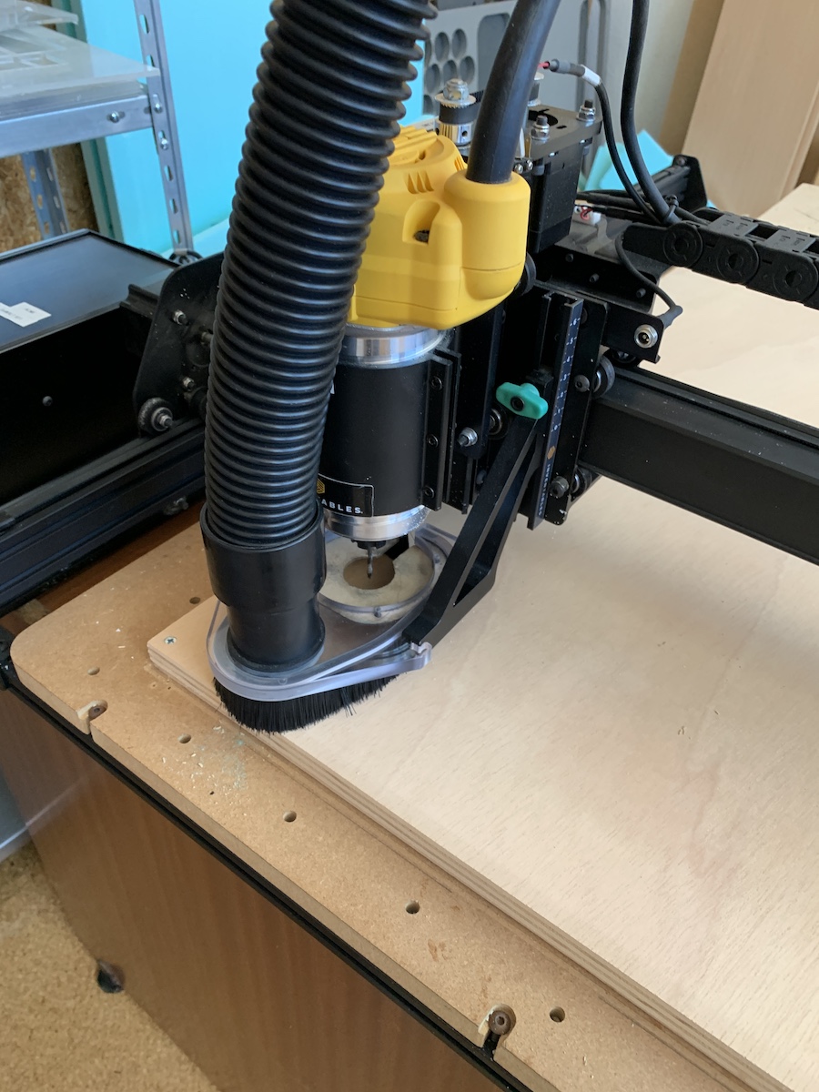
The CNC machine to be used for milling is a 1000mm X-Carve

with a Solid Carbide Ball End Mill, good for milling plywood and with 2 flutes that provides quick way to remove material:
| Description | 2F Ball Nose - 1/8’’ - Red |
|---|---|
| Diameter | 3.18mm |
| Shaft diameter | 3.18 |
| Overal length | 45.2 |
| Length below holder | 32.67 |
| Flute length | 22.47 |
| Type | Ball end Mill |
| Spindle rotation | Clockwise |
| Number of Flutes | 2 |
| Material | Carbide |
| Cutting feedrate | 1000 mm/min |
| Feed per tooth | 0.03125 |
| Lead-in feedrate | 1000 mm/min |
| Lead-out feedrate | 1000 mm/min |
| Ramp feedrate | 333.33 mm/min |
For the design and CNC machine work i’m going to keep using/learning Fusion 360. Have also installed the x-carve-tools-ver-3.tools (check screenshots for how to install).
So designing something big! From the existing lab chairs i took some measures and started to add some parameters into Fusion 360 project, like stool diameter, stool height and from the existing material, choose some plywood so added also the material width. (note: For the desing i keep tool diameter to 5mm because the End Mill was selected only after getting back to the lab, and having the diameter a bit larger wasn’t also a problem to fix).

The stool is assembled by press-fit construction (without glue or nails). Started by designing the top of the stool. Here there are 4 cuts that will then lock the legs of the stool.
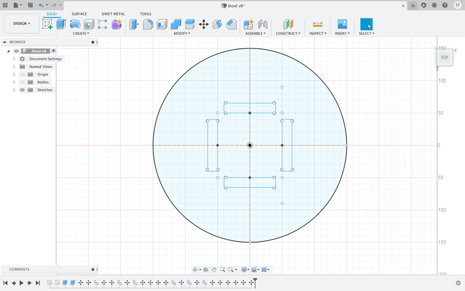
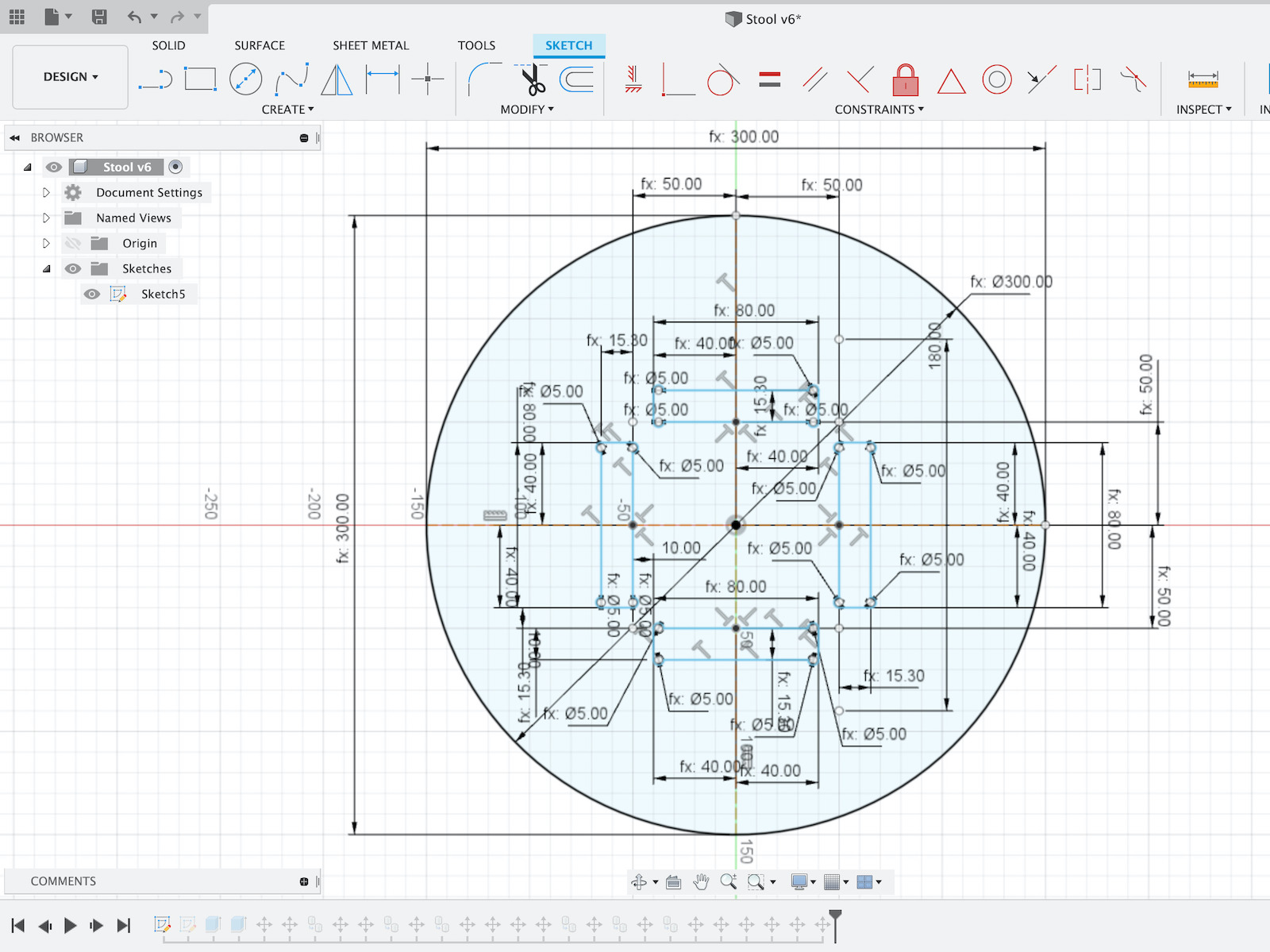
On each cut where press-fit needs to happen it was necessary to design with t-bone. This allows to have a toolpath with clean 90° slots which were impossible to have without, because the end milll is round (not like in laser cut, where a perfect 90° corner can be cut).
The top of the stool was relatively easy to design and paramterize.
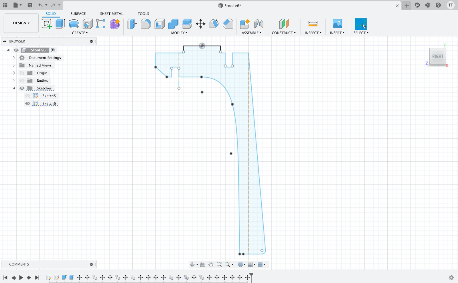
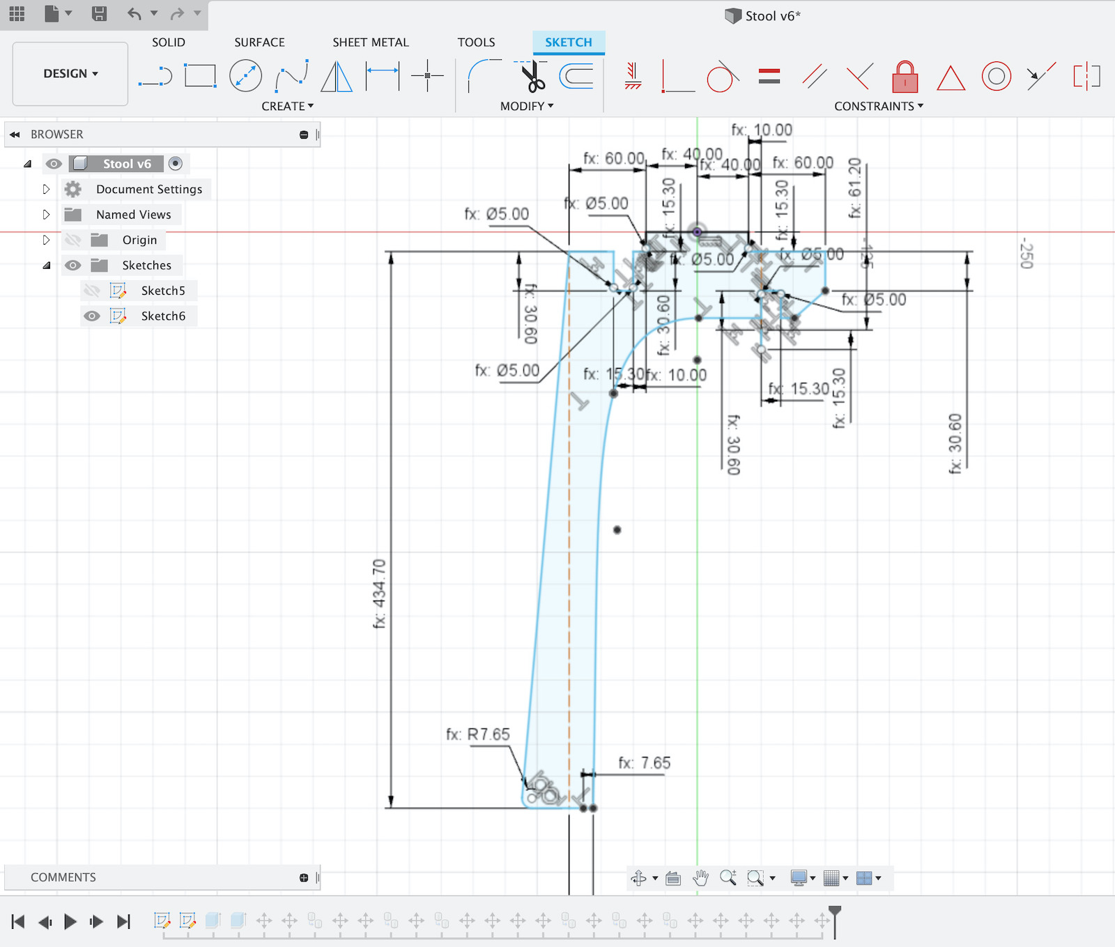
The legs, there were some iterations because once 3d model was assembled, there was some adjustments needs to have more distance between stool feet.


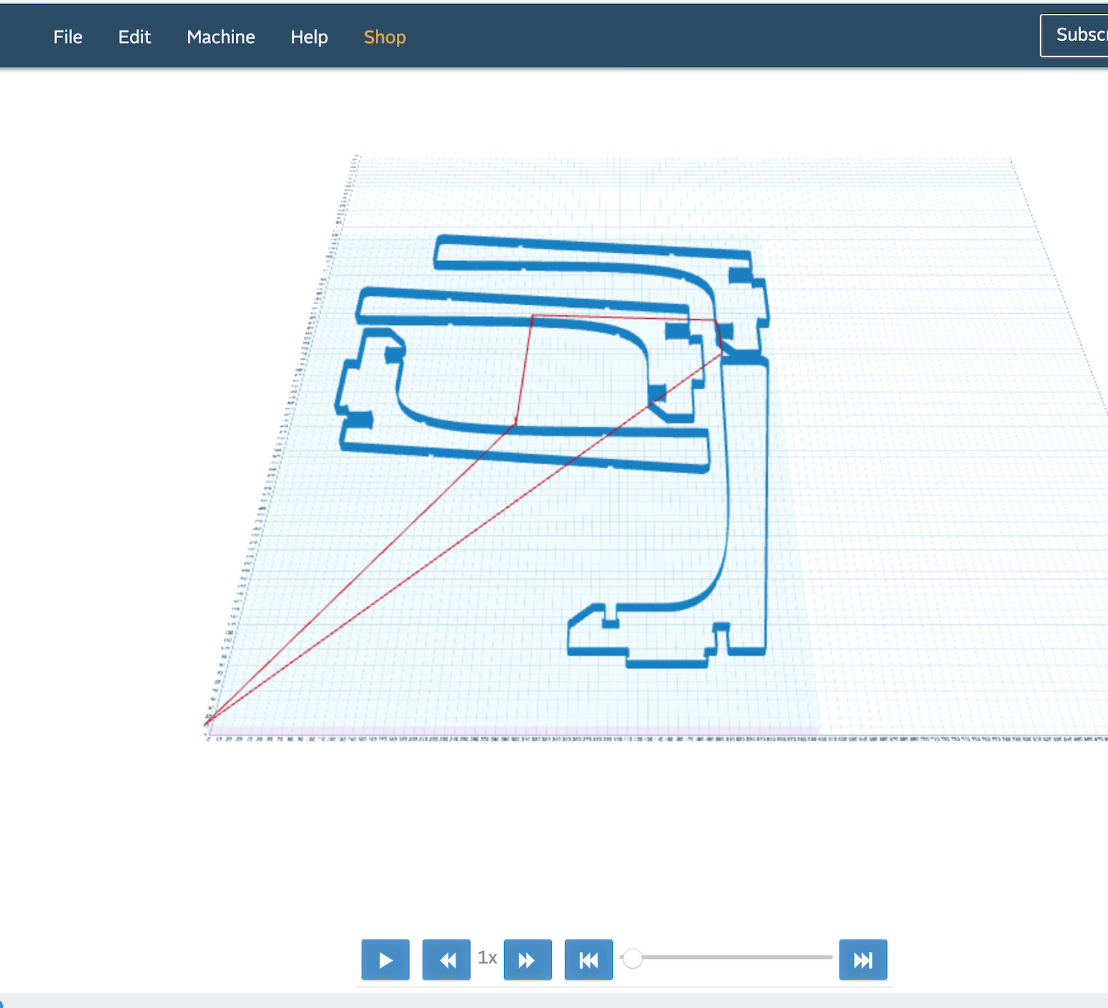
Then copied legs and lay them down on the same plane as the stool top, this was done to prepare for CAM to generate toolpaths to make the cuts.

This time used also Fusion 360 to generate the toolpaths and Inventables Easel CNC software to run the generated gcode on the X-Carve CNC.
So goind into Fusion 360 project Manufacture mode i created a setup to then generate the toolpaths.
1st step here is to create a new setup.

and select a machine, on my case have selected a “Generic 3-axis” machine.
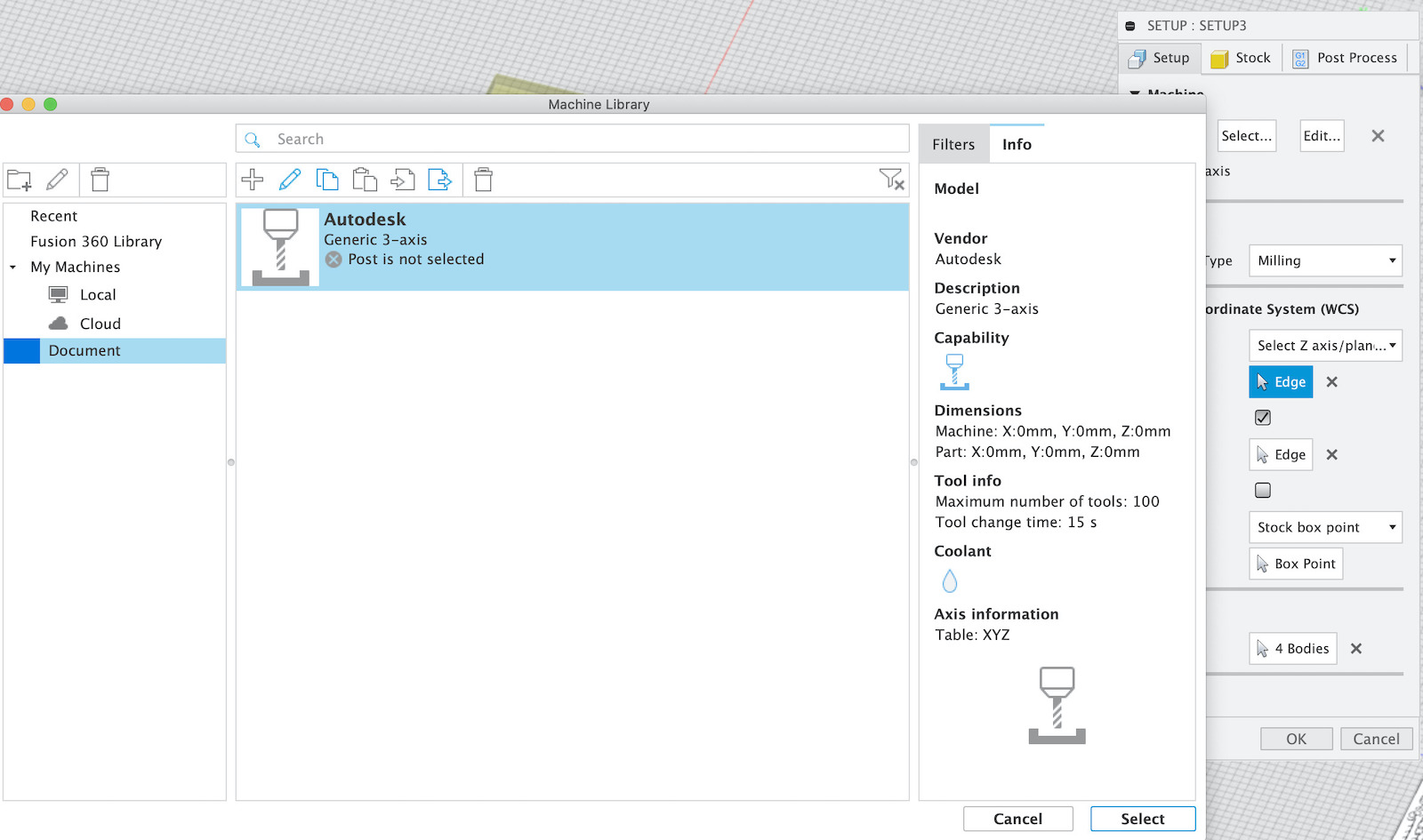
fill in Work Coordinate System by having the correct orientation, axis and point or origin. Here you can also select the bodies that are going to be used to generate the cnc work.

once the setup is filled in then needed to fill in information about Stock (the material being milled).
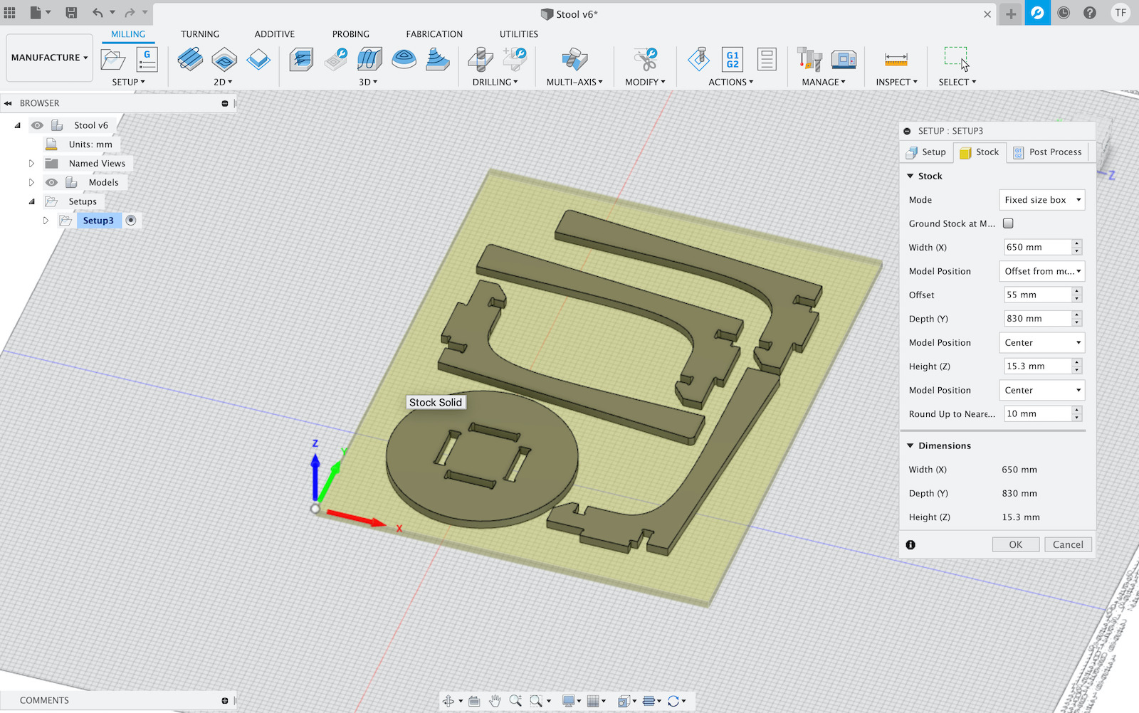
Main setup done, stock area looks correct and all parts are in place. Now it’s time to generate toolpaths, so created a 1st “2D Contour”.

For this 1st work i choose to mill the stool top as a 1st test. Selected the tool from the x-carve-tools previously installed: “2F Ball Nose - 1/8’’ - Red”.

Then configured the Feed & Speed into a more moderate feed/speed because this end mill is the only one like in the lab :)

In the Geometry have configured/enabled the Tabs.

In the Passes have enabled Multiple Depths with a conservative “1 mm” of Maximum Roughing Stepdown.

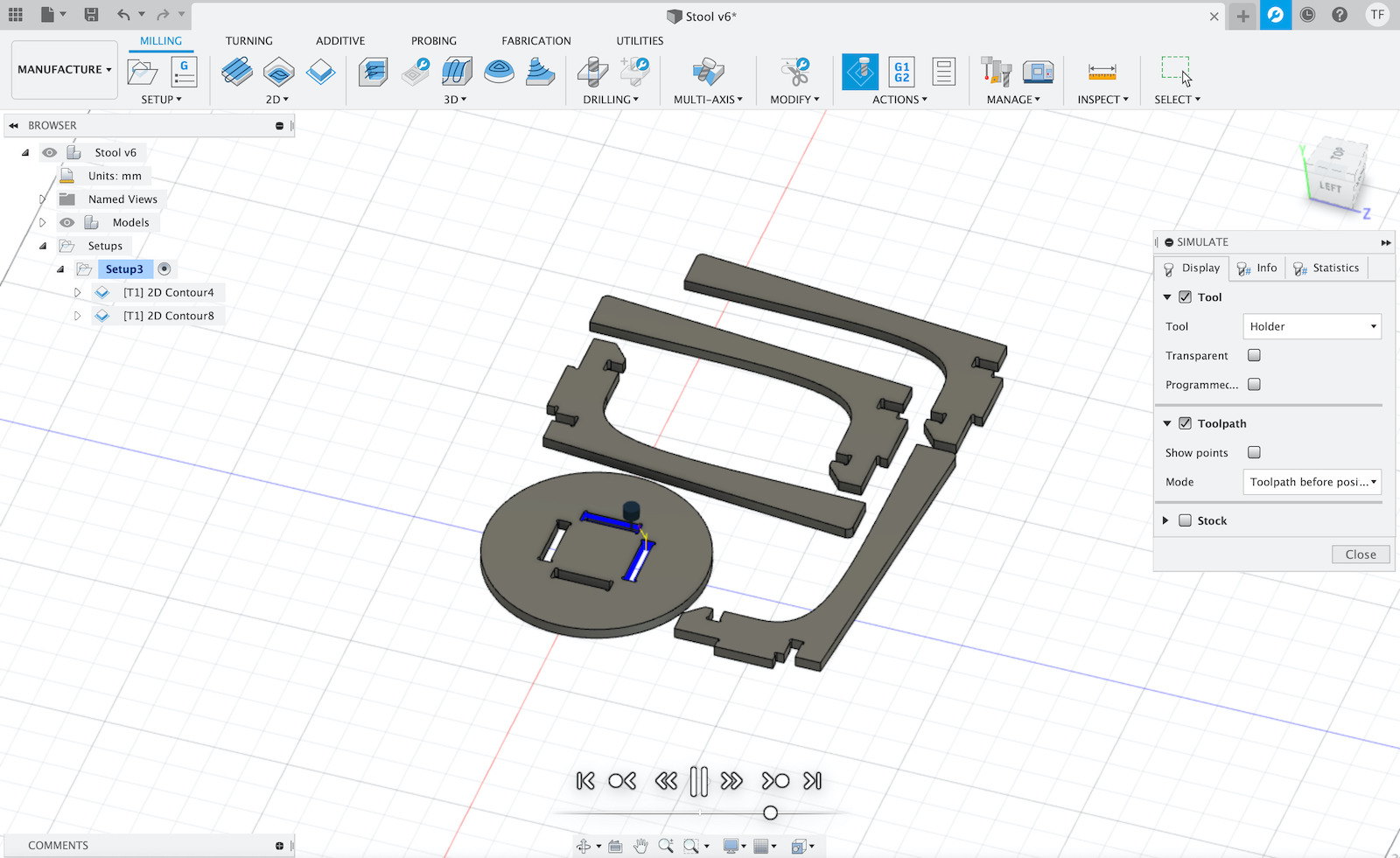
This generates the toolpath. At this point it’s possible to simulate and check how CNC should run the work.

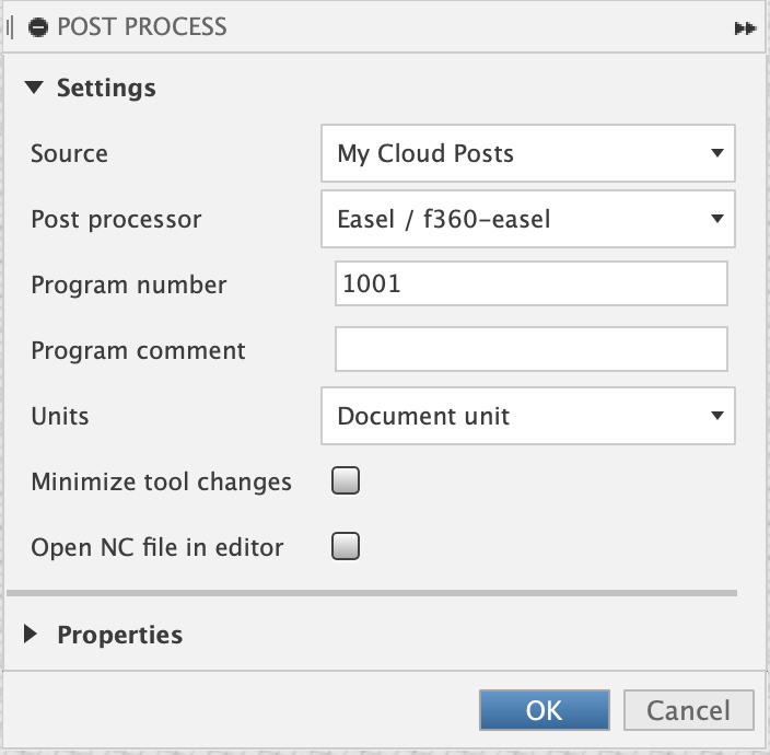
Once the toolpath is generate it’s time to have some gcode to run on the CNC. This is done via “Post Process” on the selected contour.

In my case and because i’m going to use Inventables Easel i needed to install post processor for it. Once installed selected “Easel/f360-easel” as “Post processor”, which is required by Easel when importing the gcode into a project.
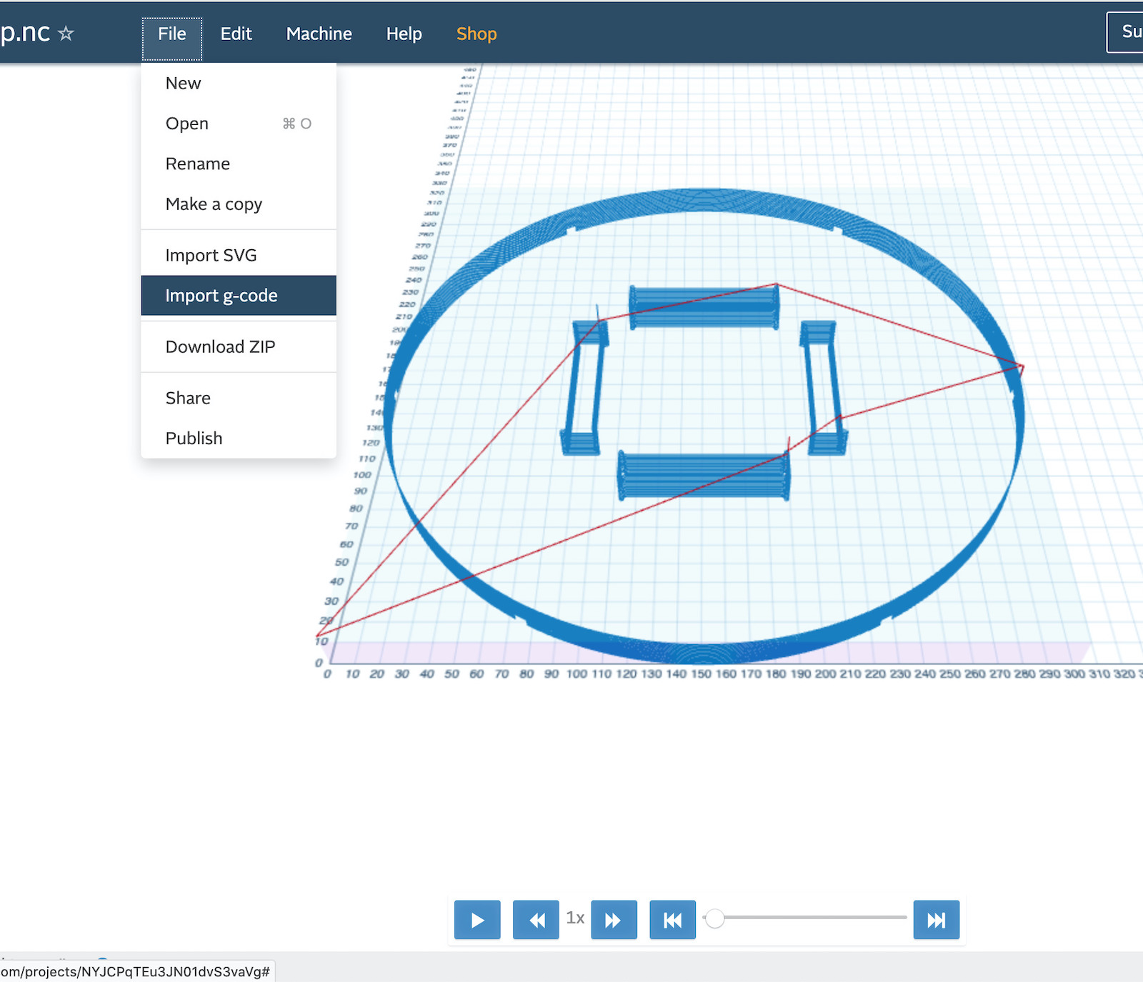
Now is just a matter of saving the .nc file and then importing into a Easel project, configure/setup machine inside Easel (follow the wizard). Opened Easel and imported the .nc file.
Not so fast…
Needed to add the stock into the CNC :) so a thin plywood was added as sacrificial layer and on top the stock/material to mill the stool. This was a plywood sheet of 830mm x 650mm x 15.3mm. To lock the plywoods in place used 4 screws at the corners that went through the stock, sacrificial layer and bolted to X-Carve bed.
So, getting back to Easel and importing .nc file.
At this point the machine was also selected and configured for project.


Once the machine is setup, then it’s time to mill some plywood… 1st test…

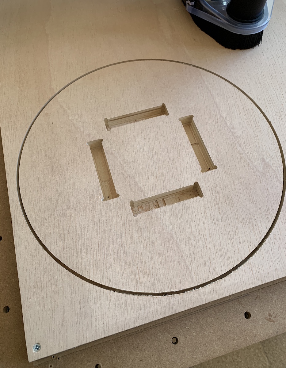
At this point i was happy to see the result! :)
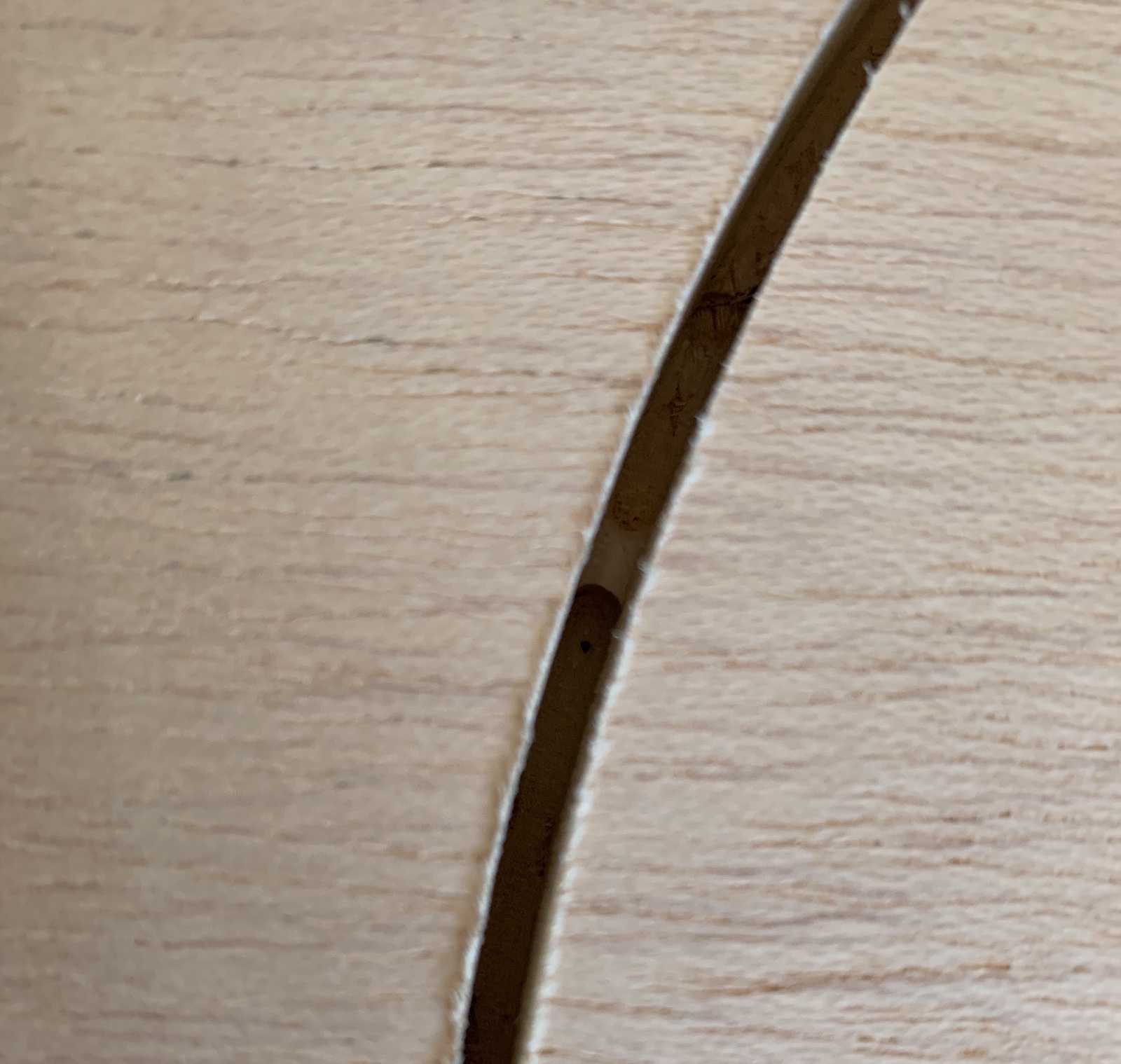
The tabs were ok, they managed to secure the stool top and could be easily removed with knife or saw.
Now for the next steps, milling the stool legs. For this created a new 2D Contour, with same parameters as the previous one but selected the base leg contours only. This will generate toolpaths only for the selected contours.

After Post processing the countour to generate gcode and import file into Easel.
For the legs milling i detected a problem with the positioning of the legs, they end-up outside de stock, and one of the legs wasn’t finished properly. Needed to stop the work after 3rd leg was done, move the 4th legs more to the left and then re-generate toolpath just for that leg and import back to Easel. In the end for the 1st try i was ok with the milling!

After some cleaning and trimming of the 1st milled version of the stool i managed to assemble it. It was a really tight press-fit, but it worked!
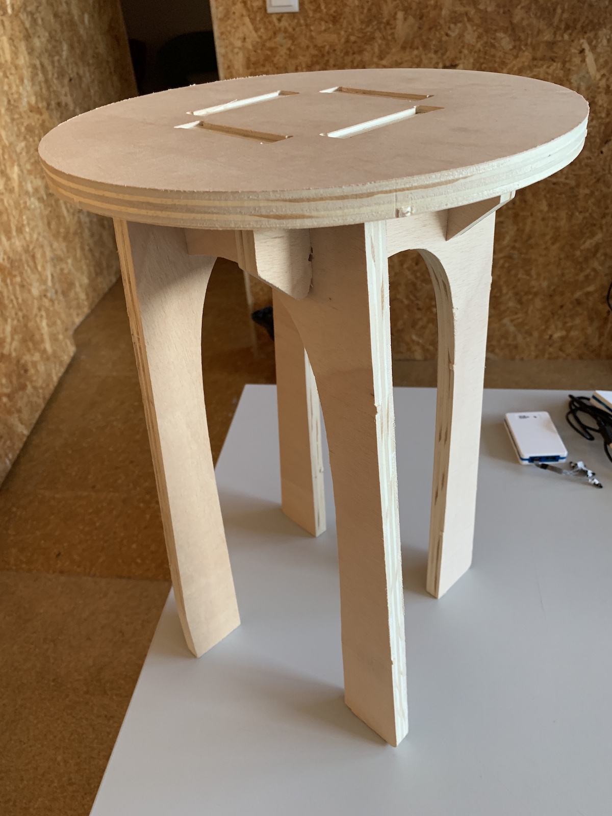
Have tested it :) it supports person seated with no problem.
Have done already some small adjustments on the press-fit, to make it easy to assemble the 4 legs and maybe will try to mill using +2mm in material width just to test how press-fit tightness could work with this plywood.
File: Fusion 360 Stool.f3d