17. Machine design
Learning outcomes
- Work and communicate effectively in a team and independently
- Design, plan and build a system
- Analyse and solve technical problems
- Recognise opportunities for improvements in the design
Have you?
- Documented the machine building process to the group page
- Documented your individual contribution to this project on your own website
- Linked to the group page from your individual page as well as from group page to your individual pages
Group assignment
For the group documentation, please check group assignment page here: Mechanical & Machine Design (Group page)
Individual assignment:
- Document your individual contribution.
Material
List of material used to actuate and automate the Spider cam Gimbal.
| Description | Quantity |
|---|---|
| Raspberry Pi Model 3 B+ | 1 |
| Tower Pro Servo SG90 (360º) | 1 |
| GOTeck Servo GS-9025MG | 1 |
| 2A Power supply for Raspberry | 1 |
| Raspberry Pi Camera Rev 1.3 | 1 |
| 3D Printed Parts from Mechanical design week | 7 |
Setup
Install Rapsberry Pi
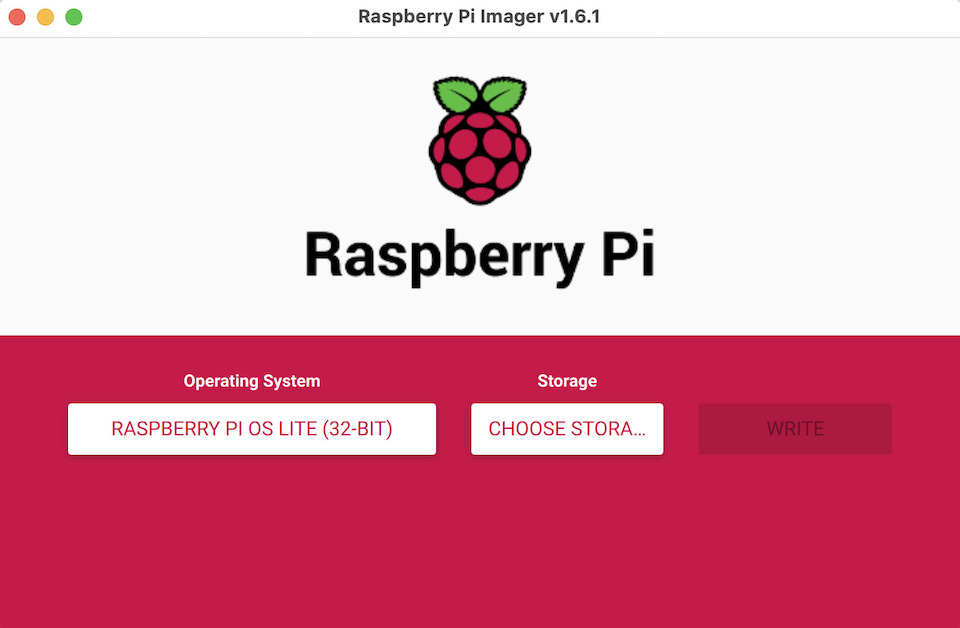
Downloaded and installed Raspberry Pi Imager, selected operating system Raspberry Pi OS Lite (Raspbian), storage (usb reader 64GB micro-sd) and clicked write.
After that i connected the raspberry to a screen, logged in with pi user (pwd: raspberry) and did the basic configuration (have set hostname to “spidercam”, so that i could try to use later http://spidercam.local to access UI). Wifi, enabled ssh, enabled camera, etc, via the raspi-config tool (This can be used also to change hostname).
sudo su - root

raspi-config
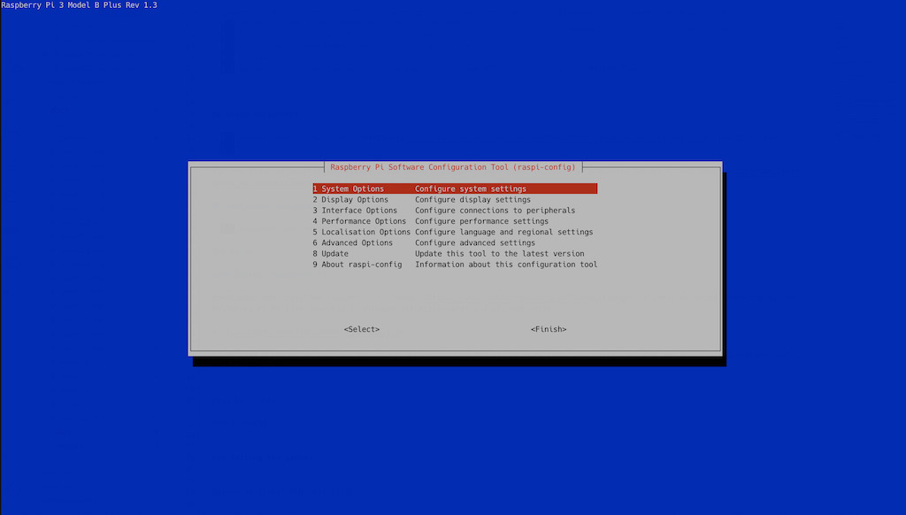
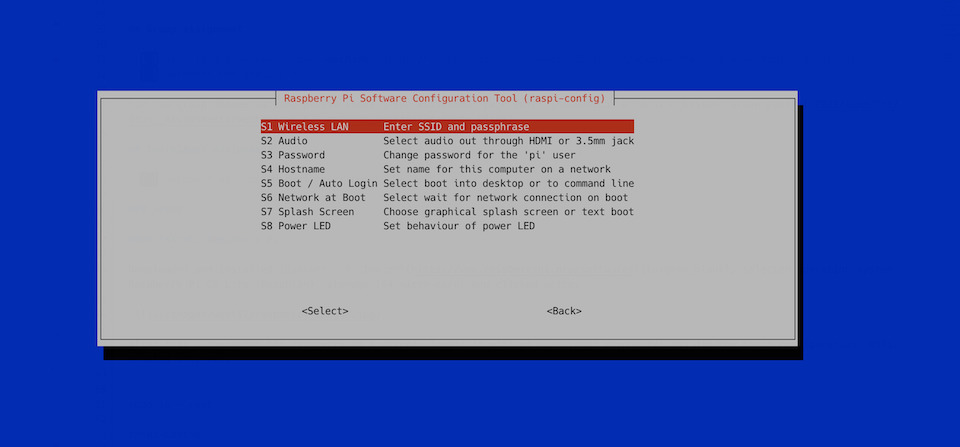
Raspi System Options: configured Wireless LAN
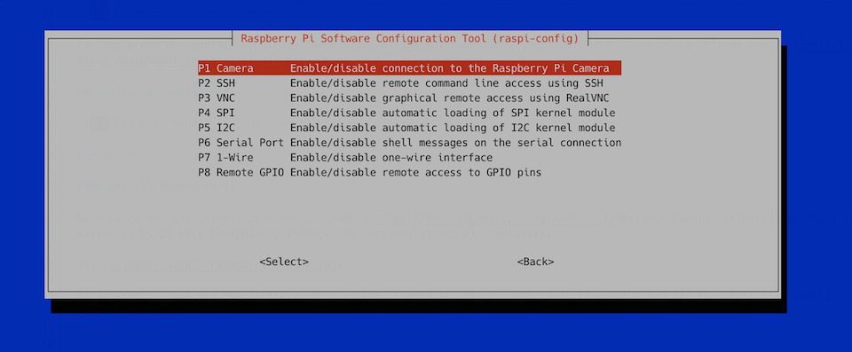
Raspi Interface Options: Enabled SSH for remote access and Camera
Besides these options have also updated the system packages, enabled full-use of micro-sd space and configured keyboard localization.
Installing necessary packages:
apt install libpigpio1 nodejs npm
Install Spider cam UI
Spider-cam-ui is based on h264-live-player that is implemented in the Express framework for Node.JS.
So once system packages are installed, copy spider-cam-ui.tgz into raspberry using scp (or wget URL), decompress, install js packages and run server-rpi.js. Just follow the commands:
$ tar zxvpf spider-cam-ui.tgz
$ cd spider-cam-ui
$ npm install
$ sudo nodejs server-rpi.js
This will open port 8080 on the IP ADDRESS of your raspberry pi (check with ifconfig -a). So if you’re connected to the same network as the raspberry pi, you user your browser and open: http://[IP_ADDRESS]:8080
Connecting Servos to Raspberry Pi
To connect the servos, 2 raspberry GPIO pins were used. One PAN and the other for PITCH.
This was configured in the spider-cam-ui, file server-rpi.js
const camera = new Gpio(12, {mode: Gpio.OUTPUT});
const gimbal = new Gpio(13, {mode: Gpio.OUTPUT});
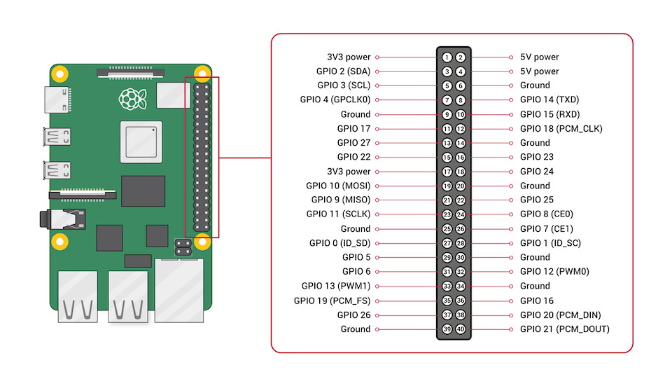
So camera is on GPIO 12 (PWM0, pin 32) and gimbal is on GPIO 13 (PWM1, pin 33). Servos are connected to GND (pins 6 and 9) and 5V power (pins 2 and 4).
These pins will be used by spider-cam-ui when clicking in the interface buttons. They will trigger GET requests to server-rpi url and mapped to code that updates the pwm value in the pins making servos rotating or set into a specific angle.
This mapping is implemented in server-rpi.js:
// "/tilt/90" url is mapped to this GET and sets camera tilt angle
app.get('/tilt/:angle', function (req, res) {
    let id = req.params.angle;

    let min_pwm = 630 // 0º
    let max_pwm = 2475 // 180º

    let pwm_value = Math.round(parseInt(id) * (max_pwm-min_pwm) / 180) + min_pwm;

    camera.servoWrite(pwm_value);
})

// "/pan_right" url is mapped to this GET and rotates camera clockwise
app.get('/pan_right', function (req, res) {
    gimbal.servoWrite(1600);
    setTimeout(function(){ gimbal.servoWrite(1500); }, 100);
})

// "/pan_left" url is mapped to this GET and rotates camera counter-clockwise
app.get('/pan_left', function (req, res) {
    gimbal.servoWrite(630);
    setTimeout(function(){ gimbal.servoWrite(1500); }, 100);
})
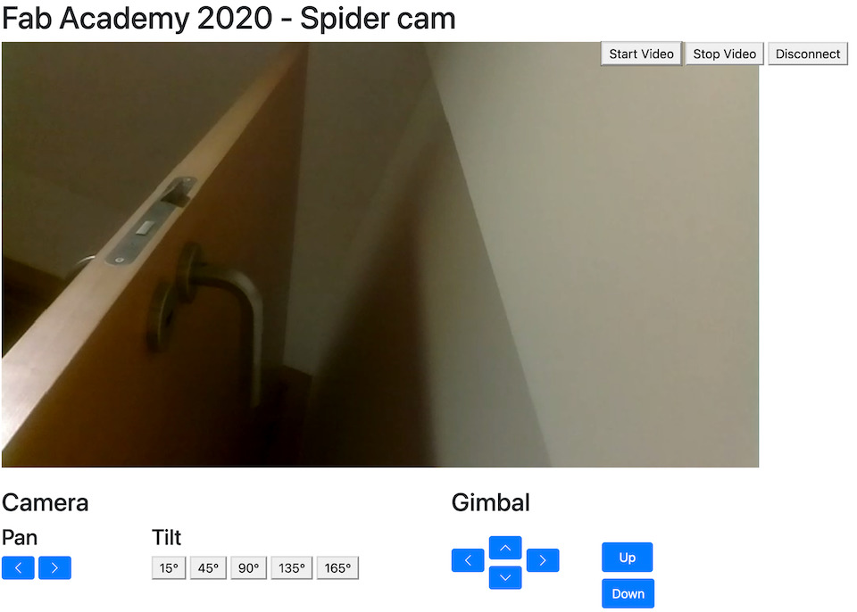
The public/index.html file is the default page that is served by server-rpi and defines the interface to display video from Raspberry Pi Camera and buttons to move the gimbal.
For example, button to PAN left:
<button class="btn btn-primary" type="button" onclick="panLeft()">
    <svg class="bi bi-chevron-left" width="1em" height="1em" viewBox="0 0 16 16" fill="currentColor"
      xmlns="http://www.w3.org/2000/svg">
    <path
      fill-rule="evenodd"
      d="M11.354 1.646a.5.5 0 0 1 0 .708L5.707 8l5.647 5.646a.5.5 0 0 1-.708.708l-6-6a.5.5 0 0 1 0-.708l6-6a.5.5 0 0 1 .708 0z" />
  </svg>
</button>
The panLeft() function is implemented in the public/javascript/spidercam.js file:
var panLeft = function(){
  xhttp.open("GET", "/pan_left", true);
  xhttp.send();
};
So when button is pressed, browser makes a GET request to url “/pan_left”, server-rpi processes the request and makes servo move.
All the other interface functions are implemented in public/javascript/spidercam.js file.
Testing the gimbal
SpiderCam Gimbal PAN test (1/3)
SpiderCam Gimbal Pitch test (2/3)
SpiderCam Gimbal test (3/3)
SpiderCam Control Interface used to test/control the gimbal in YAW/PAN and Pitch.
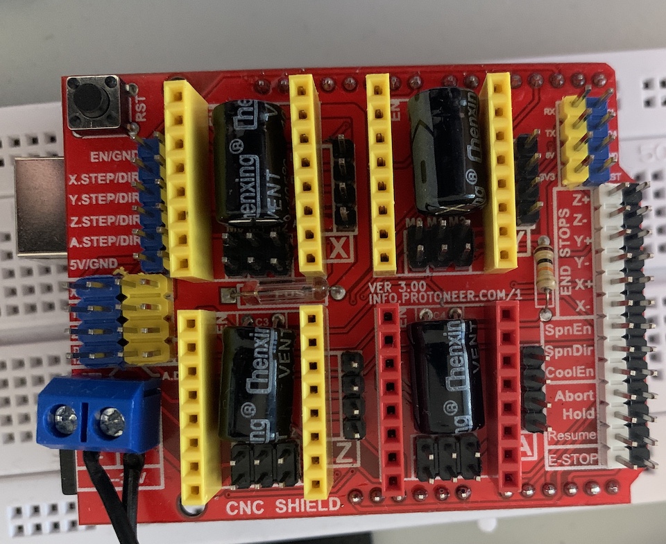
Stepper motor control to move gimbal around
To move the gimbal around the spider cam uses 4 stepper motor. These are controlled with Arduino CNC Shield v3.0 and A4988 stepper motor driver.
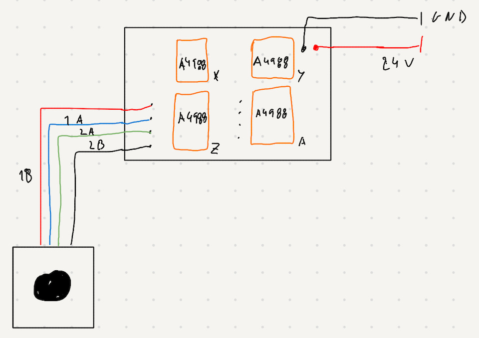
Connection between a stepper motor coils (1A, 1B, 2A and 2B) and A4988 driver.
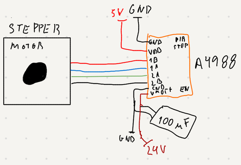
The shield provides a way to have 4 of these steppers running on top of Arduino.
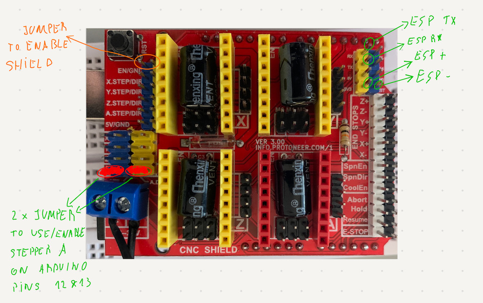
We decided that the commands to the Arduino CNC shield were going to be sent by Raspberry Pi via wifi, less cables going to the gimbal. So we connected a ESP8266 to the CNC shield using serial connection (TX/RX).
Arduino CNC Shield connections:
So the Arduino can receive via serial commands in the form of a char and make steppers act accordingly (‘u’ - Up, ‘d’ - Down, ‘l’ - Left, ‘d’ - ‘Down’).
Example of move bimbal to the right:
if(command == 'r'){
  //right
  digitalWrite(dirPinX, LOW);
  digitalWrite(dirPinY, LOW);

  spin_motors(stepPinX,stepPinY, stepsPerRevolution);

}
Because we were using a Arduino, the development was done with Arduino IDE. You can download and check the full stepper.tgz file.
For the ESP8266 started from ESP8266WebServer HelloServer and made changes to connect to wifi network (STASSID and STAPSK), setup Serial connection and defined the handles for the command requests.
Example of move down:
server.on("/move/d", [](){
  Serial.println('d'); // send command to Arduino
  server.send(200, "text/plain", "move down");
});
To program the ESP8266 used also Arduino IDE to compile and upload the firmware. For the full example you can download esp8266-spidercam.tgz file.
Note
To have ESP8266 ready to receive compiled program from Arduino IDE you need to:
- Connect GPIO 0 to GND
- Connect RESET to GND
- then disconnect GPIO 0 from GND and in last disconnect RESET from GND
For the Arduino with the CNC Shield on top, the program requirements was to read a char from serial connection with esp8266 and execute the correct movement by controlling the stepper motors.
This is done in the loop(). Example of code that reads char and in case char is ‘l’ it will configure stepper dir pins and rotate steppers accordingly to move spidercam to the left.
void loop(){

  if (Serial.available() > 0) {
    command = '0';

    // read byte
    command = Serial.read();

    // dir pin set to:
    //  - LOW rotates servo counter-clockwise
    //  - HIGH rotates servo clockwise

    switch(command){
      case 'l':
        //left
        digitalWrite(dirPinX, HIGH);
        digitalWrite(dirPinY, HIGH);
        digitalWrite(dirPinZ, LOW);
        digitalWrite(dirPinA, LOW);

        spin_motors(stepPinX, stepPinY, stepPinZ, stepPinA, stepsPerRevolution);
        break;
The arduino code can be found in stepper.tgz. The program controlls all 4 steppers using the CNC Shield.
Initially for development/testing purposes the setup was done with only 2 stepper motors from a 3D printer…
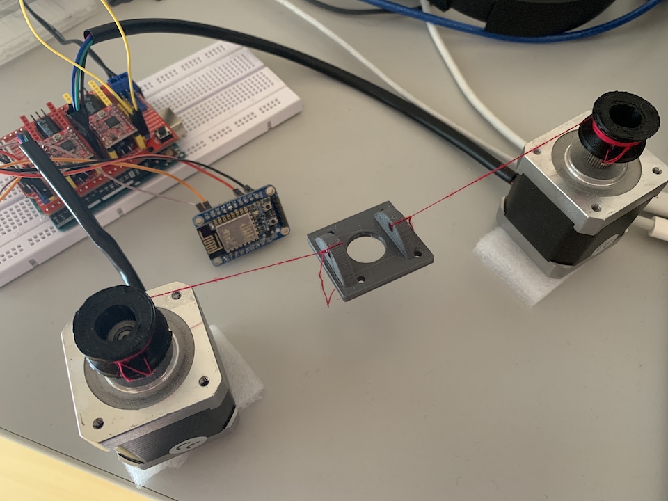
And so it moves!
Improvement
After running some tests with 4 motors, moving the gimbal, it was clear that we needed to control the acceleration/deceleration of it. During Global Open Time, Marius received feedback from Quentin regarding a lib he uses all the time to controll stepper motors (https://www.airspayce.com/mikem/arduino/AccelStepper/).
So downloaded AccelStepper-1.61.zip, installed on Arduino IDE 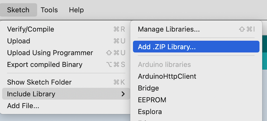 and modified previous code to use this library.
Updated version: stepper-accel.zip
The spider-cam-ui.tgz was updated to receive the Gimbal button requests once clicked and make the respective http GET request to the ESP8266 to move the steppers.
For example, the Gimbal left button on the interface will trigger the ‘move/l’ on the Raspberry that will then GET “/mode/l” on the Ardruino via ESP8266 that is available in http://spidercamctl.local (same wifi network).
...
const request = require('request');
...

const spiderCamController = "http://spidercamctl.local";

...

// Gimbal controll
app.get('/move/l', function(req,res){
    request(spiderCamController + "/move/l", function (error, response, body) {
        console.log('error:', error);
        console.log('status code:', response && response.statusCode);

    });
})
The ESP8266 receives ‘/move/l’ and writes the char ‘l’ into serial connection with Arduino.
  server.on("/move/l", [](){
    Serial.println('l');
    server.send(200, "text/plain", "move left");
  });
Please check group assignment for final work and spider-cam action.