7. Electronics design
Learning outcomes
- Select and use software for circuit board design
- Demonstrate workflows used in circuit board design
Have you?
- linked to the group assignment page
- Documented what you have learned in electronics design
- Explained problems and how you fixed them, if you make a board and it doesn’t work; fix the board (with jumper wires etc) until it does work.
- Included original design files (Eagle, KiCad, - whatever)
- Included a ‘hero shot’ of your board
- Loaded a program and tested if your board works
Work notes
So COVID-19 striked on Europe and also in Portugal. This means that FCT FabLab will be closing and we were advised not to go to the lab.
Electronics design means that we need to design and create a PCB by using a cnc to mill the design. So decided to adquire a small/cheap cnc for this.
My 1st real contact i had with a cnc was on Electronic production week. Took me a bit of time to mount the cnc, test it (breaking bits, trashing PCBs, etc :)) and learn a bit more about it.
Started testing the CNC with Univeral G-Code Sender. And then get back to JPadie, to mill the PCBs, same used on FCT FabLab.
The CNC board didn’t have auto-level probe plug. But the CNC had Grbl v0.9 and i discovered that pin A5 of the ATmega328 is used for probing. This pin on the cnc wasn’t connected to any part of the circuit, so hacked the bord by soldering a wire on the pin of the ATmega328 and made the auto-level work! The current fab academy learnings about microcontrollers came in handy :)

Then needed to setup FlatCAM on my computer. Replicated the same design rules and params used on Electronic production. The 1st PCBs were milled out of scale (bigger, see image below) and i needed to find out why. With the help of FabLab Guru Filipe Silvestre, that directed me to the exact problem and gave me tips on how to solve it, i manage to confirm that the problem was cnc calibration (the steps_per_mm weren’t correctly configured). After doing some measurements on X and Y axis (expected movement of about 50mm), took note of the real movement to calculate the correct new step_per_mm value (yes, found out that this is something we can configure on printer Grbl: $100, $101, $102).
Have also learned to work with JSCut, used it with a simple svg rectangular draw to make a 2mm depth cut in the wood that supports the pcb, so that they are horizontal align with mill (this helped auto-level to work also properly).
Files:
- rectangular draw (note: from the JSCut generated gcode, added ‘M3 S11000’ in the beginning of gcode and ‘M3 S0’ in the end to start/stop router.)
- gcode
- JSCut base settings
In the end manage to have a working CNC to use to mill the circuits at home! #win
Group assignment
For the group documentation, please check group assignment page here: Electronics design (Group page)
Individual assignment
- Redraw one of the echo hello-world boards or something equivalent, add (at least) a button and LED (with current-limiting resistor) or equivalent input and output, check the design rules, make it, test it.
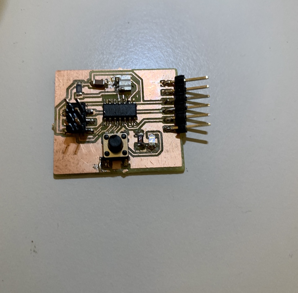
For the individual assignment have redraw the ATtiny44 hello-world board with a push-button (using internal pull-up) and a blue led (with a 1k current-limiting resistor, to drop the voltage so that the led works properly without burning).
| Components | Quantity |
|---|---|
| ATtiny44A-SU | 1 |
| ECS-CR2-20.00-B-TR (20Mhz Resonator) | 1 |
| R 1K ohm SMD 1206 | 1 |
| R 10K ohm SMD 1206 | 1 |
| Blue LED SMD | 1 |
| Mini button 6x6x(7.3mm) SMD | 1 |
| Capacitor 1uF SMD | 1 |
| Headers 2x3 | 1 |
| FTDI header | 1 |
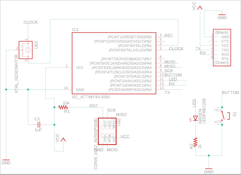
The circuit board design was done in Eagle, this is the one i’m learning and will keep using it for now.
After creating the Eagle project and schematic, added all components and started to connect the components (same process alredy done on Electronic production week). This time have also used Names to connect them, instead of having a buch of nets around (makes the design a bit more clean).
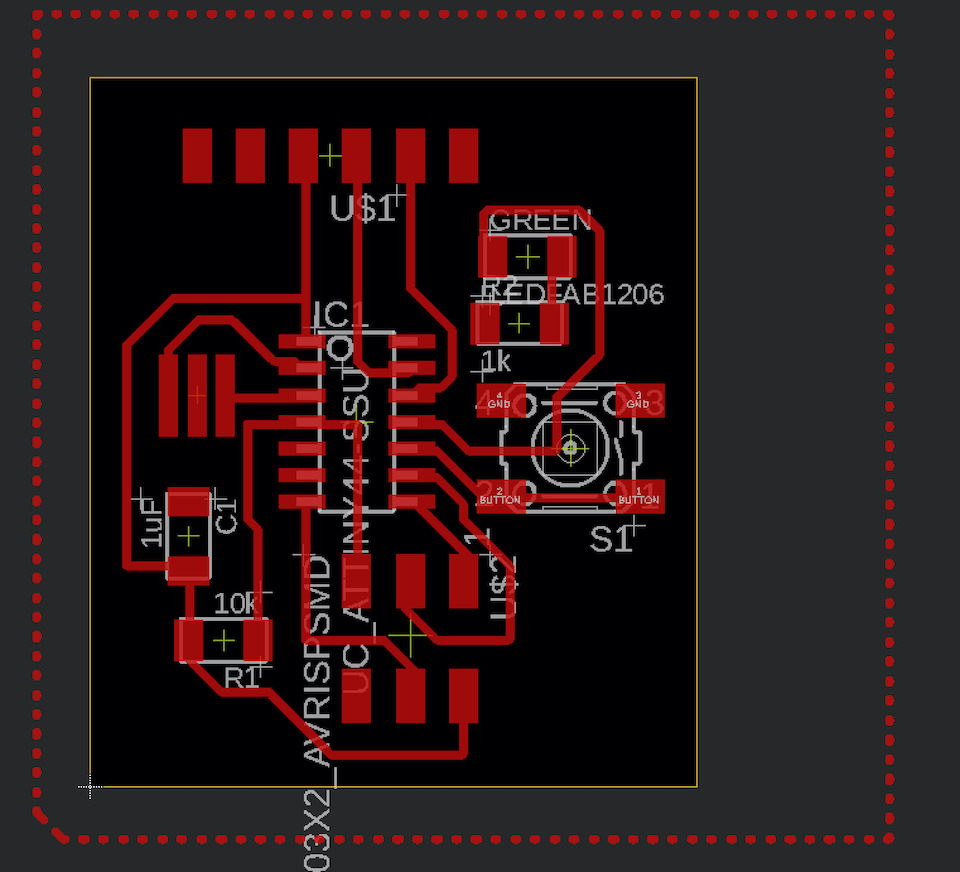
Then created the board, following same design rules of Electronic production week, all in mm.
![]()
This was the final design after trying to have components arranged in other ways. Have used autorouter option with final adjustments to have 100% wiring coverage.
The only difference in process from Electronic production week week is that i used a  and assigned GND signal to it (you can see in the image below, the area with dashed lines). This way all PCB was GND and the milling was done to separate the other signals. Wanted to test this and check if on this case it could help on routing the signals and think it did, not having to draw specific routes to GND.
You can download the Eagle project here: HelloBoard.zip
Then on Eagle clicked to “Generated CAM data” and opened the generated .zip file to fetch “CAMOutputs/GerberFiles/copper_top.gbr”. Opened FlatCAM with units in mm and opened the copper_top.gbr file.
Used same steps as in Electronic production week, being the spingle speed changed to 11000 because of my CNC. So generated the isolation geometry, generated the CNC job and saved the CNC code.
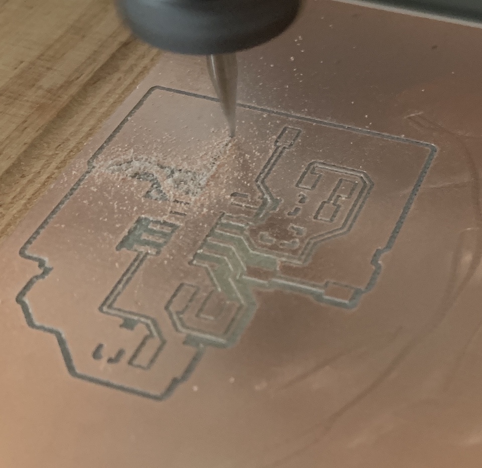
Up to this point it was ok. From this point forward, the CNC work was a bit of a challenge and work like described in the notes. Anyway, in the end managed to have a milled PCB in the correct size and ready for stuffing! (True, but before the last pcb i trashed some 2 or 3 milled pcbs while trying to figure out how to make the cutout margins and gaps :) also a “problem” solved)
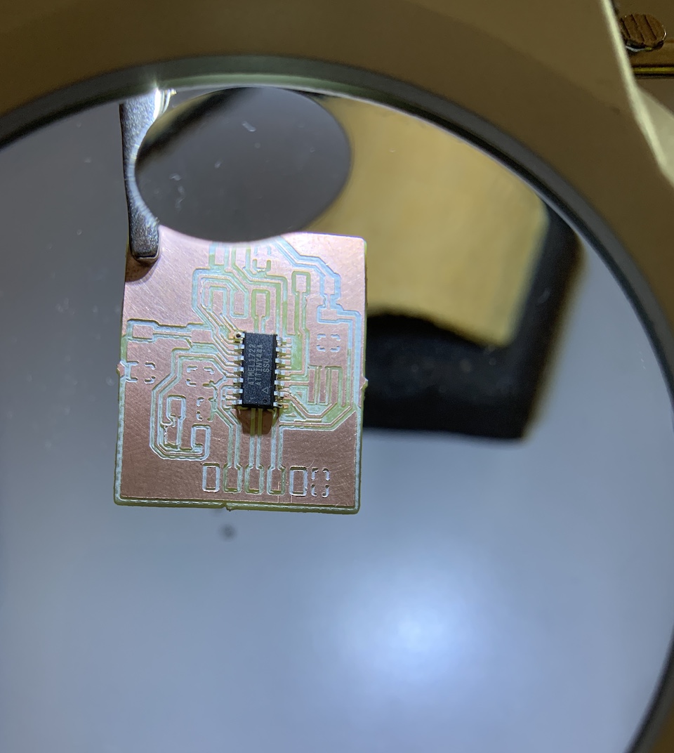
And after some time and soldering and desoldering (to correct LED polarity and board debug because it wasn’t working, resonator not soldered correctly to the GND), the board was finished.
For the programming followed the hello.ftdi.44.program guide.

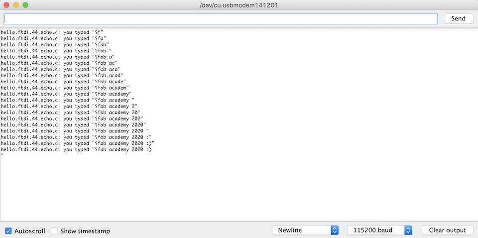
Managed to program the board with the hello.ftdi.44.echo.c and hello.ftdi.44.echo.c.make.
➜  hello.ftdi.44.echo git:(master) ✗ make -f hello.ftdi.44.echo.c.make program-usbtiny
avr-objcopy -O ihex hello.ftdi.44.echo.out hello.ftdi.44.echo.c.hex;\
    avr-size --mcu=attiny44 --format=avr hello.ftdi.44.echo.out
AVR Memory Usage
----------------
Device: attiny44

Program:      78 bytes (1.9% Full)
(.text + .data + .bootloader)

Data:          0 bytes (0.0% Full)
(.data + .bss + .noinit)


avrdude -p t44 -P usb -c usbtiny -U flash:w:hello.ftdi.44.echo.c.hex

avrdude: AVR device initialized and ready to accept instructions

Reading | ################################################## | 100% 0.00s

avrdude: Device signature = 0x1e9207 (probably t44)
avrdude: NOTE: "flash" memory has been specified, an erase cycle will be performed
         To disable this feature, specify the -D option.
avrdude: erasing chip
avrdude: reading input file "hello.ftdi.44.echo.c.hex"
avrdude: input file hello.ftdi.44.echo.c.hex auto detected as Intel Hex
avrdude: writing flash (78 bytes):

Writing | ################################################## | 100% 0.15s

avrdude: 78 bytes of flash written
avrdude: verifying flash memory against hello.ftdi.44.echo.c.hex:
avrdude: load data flash data from input file hello.ftdi.44.echo.c.hex:
avrdude: input file hello.ftdi.44.echo.c.hex auto detected as Intel Hex
avrdude: input file hello.ftdi.44.echo.c.hex contains 78 bytes
avrdude: reading on-chip flash data:

Reading | ################################################## | 100% 0.21s

avrdude: verifying ...
avrdude: 78 bytes of flash verified

avrdude: safemode: Fuses OK (E:FF, H:D7, L:5E)

avrdude done.  Thank you.
And echo program was running!
** Notes: **
- I don’t have a video for the echo program but did made a video for Week 9 “Embedded programming” demonstrating the led blink.
- Should have calculated the value of the current-limiting resistor and not just use 1k resistor from some example.
To calculate the value of the current-limiting resistor R = V / I, so:
R = (Vs - Vl) / I
- Vs: supplied voltage, on this case 5V, theoretical max of the attiny44 on pin output.
- Vl: working voltage of the led: 3.2V
- I: 20 mA
So resistor value should have been: R = (5 - 3.2) / 0.02 = 90 ohm