15. Mechanical design
Learning outcomes
- Work and communicate effectively in a team and independently
- Design, plan and build a system
- Analyse and solve technical problems
- Recognise opportunities for improvements in the design
Have you?
- Documented the machine building process to the group page
- Documented your individual contribution to this project on your own website
- Linked to the group page from your individual page as well as from group page to your individual pages
Group assignment
For the group documentation, please check group assignment page here: Mechanical & Machine Design (Group page)
Individual assignment
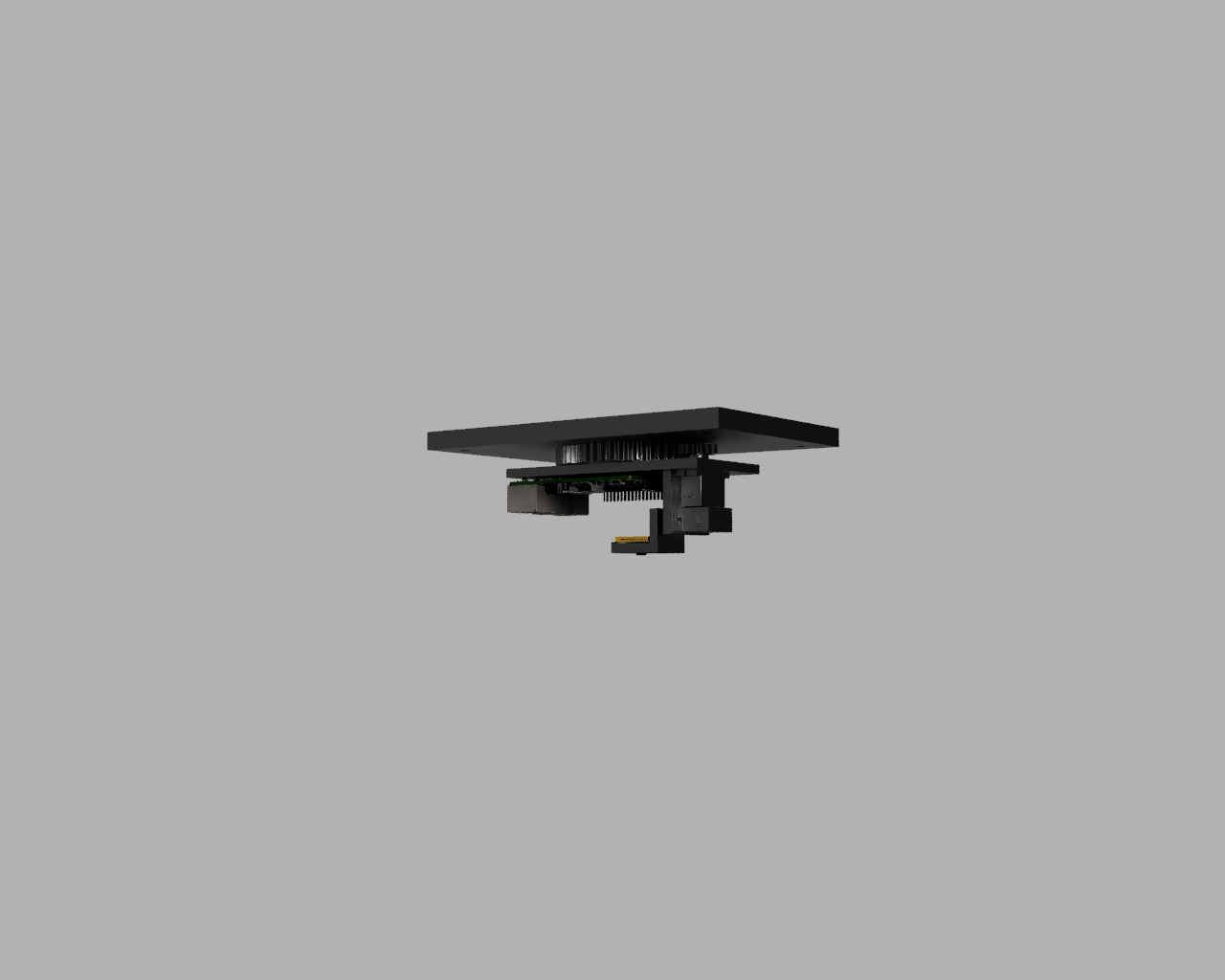
For this week my task is to design and prototype the spidercam camera gimbal that will be suspended by cable system. The plan is to allow gimbal to rotate left/right (YAW/PAN) and camera up/down (Pitch). So started by designing a “simple” gimbal to be used in the project, using Fusion 360 and importing the Raspberry Pi 3 b+ model and SG90 9g micro servo 3D models.
At the time of lockdown the material we had for this was a Raspberry Pi with Pi camera. So the design was done around the use of this material.
The 1st design/mockups of the gimbal
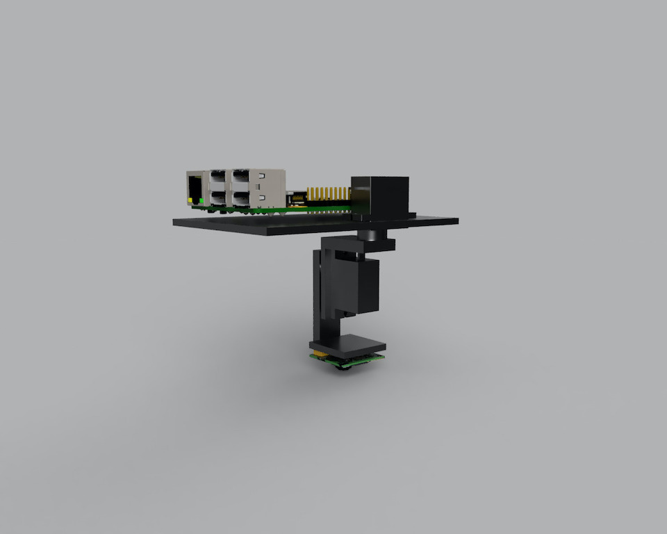
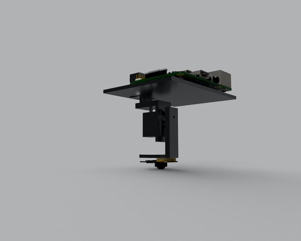
2nd iteration:
So the idea here as was to prototype something fast that could work but there were limitations. The flat cable that connects the Raspberry Pi to the camera it’s not flexible or made to move a lot and the length of it does also limit the movement of the camera.
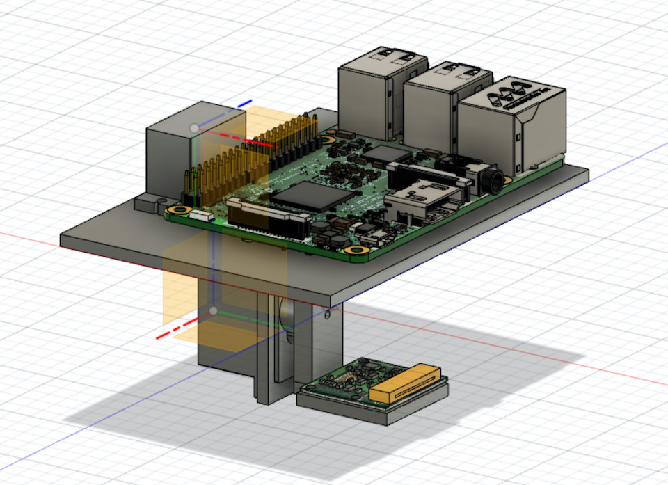
Time to iterate on the design.
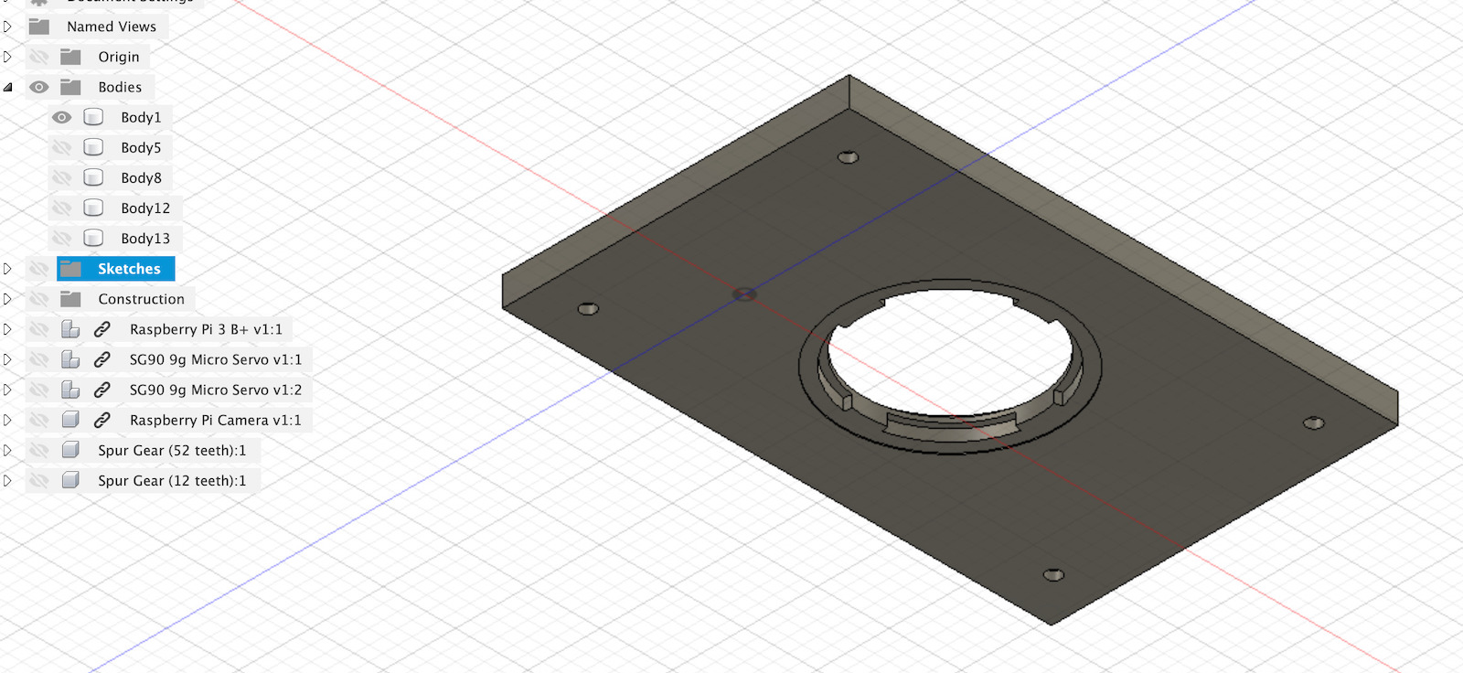
The improvement here would require the board to rotate with the camera and the camera flat cable would just pitch up/down. So the current This made me change the design to incorporate Spur Gears for YAM/PAN rotation. The current design would also need to attach somehow to this rotating axes.
Keept using Paper on iPad to draw, usefull to visualize and then design.
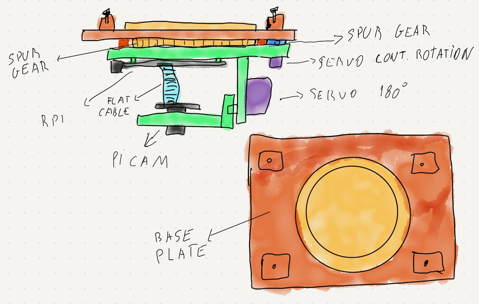
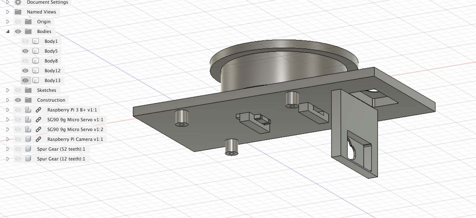
The next iteration looked like this, so base plate where cables would tie had a center axes that would lock the Raspberry Pi support base with lock mechanism influenced by press-fit kit.
The continuous rotation servo has a small spur gear that connects to the one in the base plate and this mechanism makes the Raspberry Pi support rotate. Then the 180º servo is used to pitch the camera.
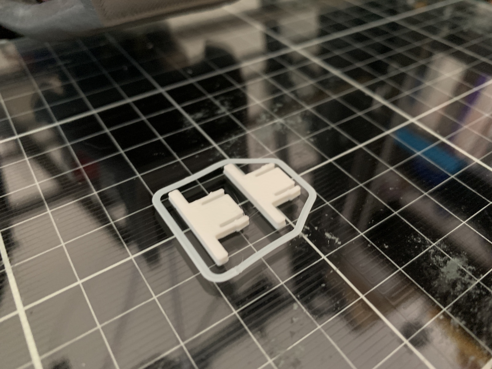
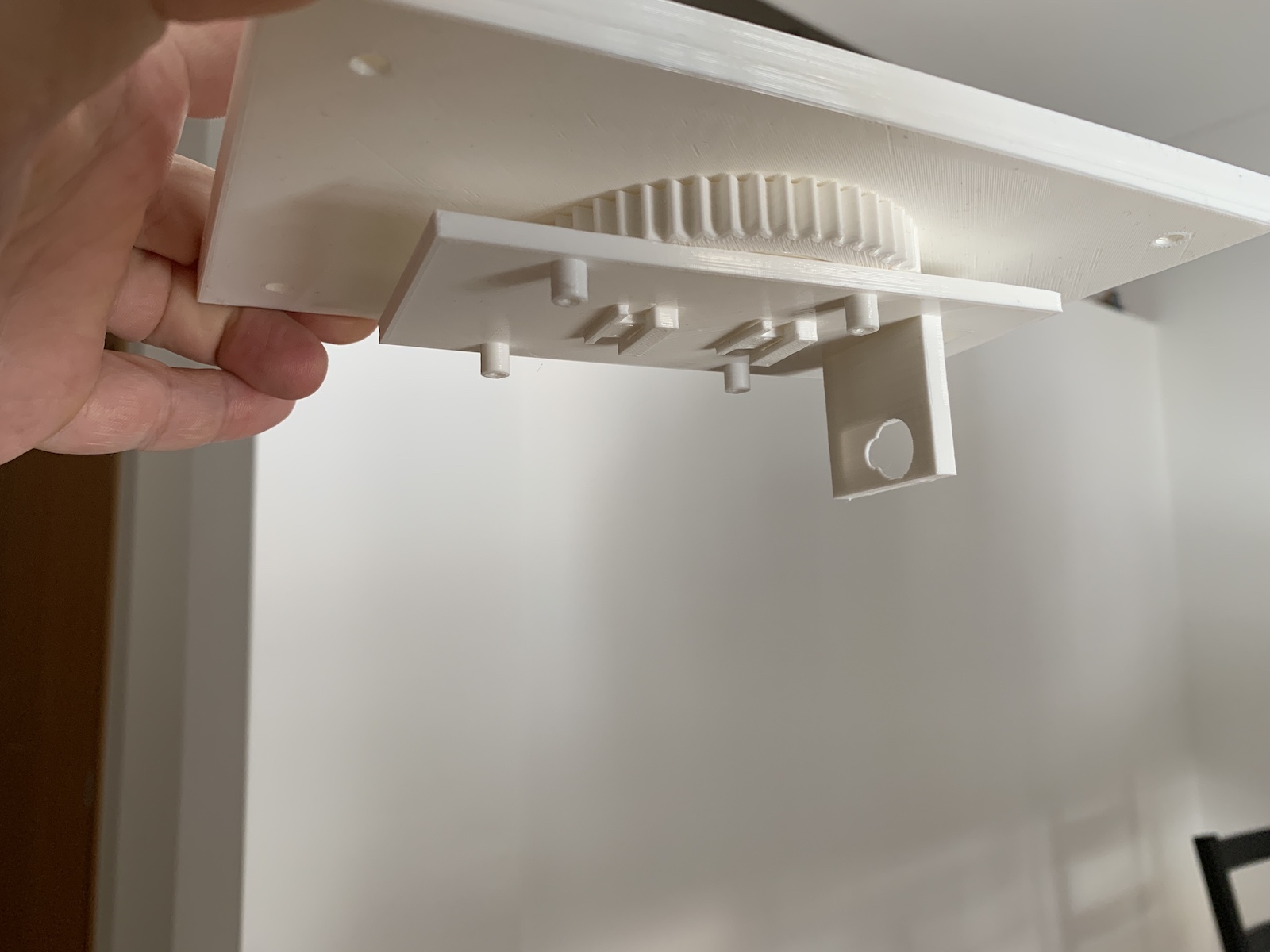
Time to 3d print. The 1st time i printed the full kit, i detected a small issue… the spur gears were too much close, they didn’t fit and allow to rotate :/ Also if i wanted to test with different spur gear sizes i would need to print the base plate all the time. So i decided to have the base place spur gear printed apart from base place with some socket/lock mechanism.
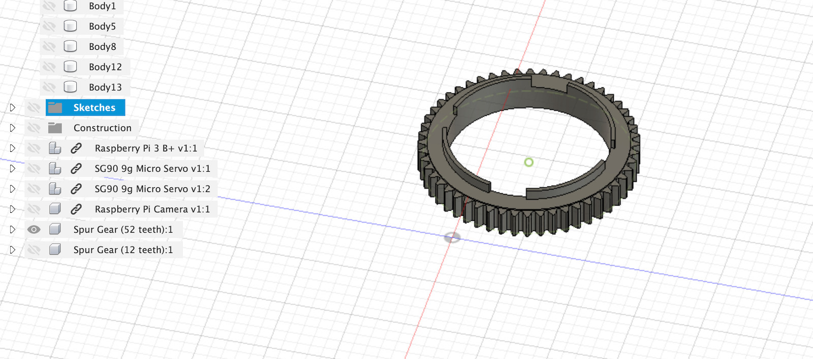
This way i can just change/test different spur gears and just need to 3d print then, without the need to print a full base plate.
To allow the rotations axes to work and lock the Raspberry support, designed a small chaft that allows to slot into Raspberry support plate and be locked by press-fit kit inspired feature.
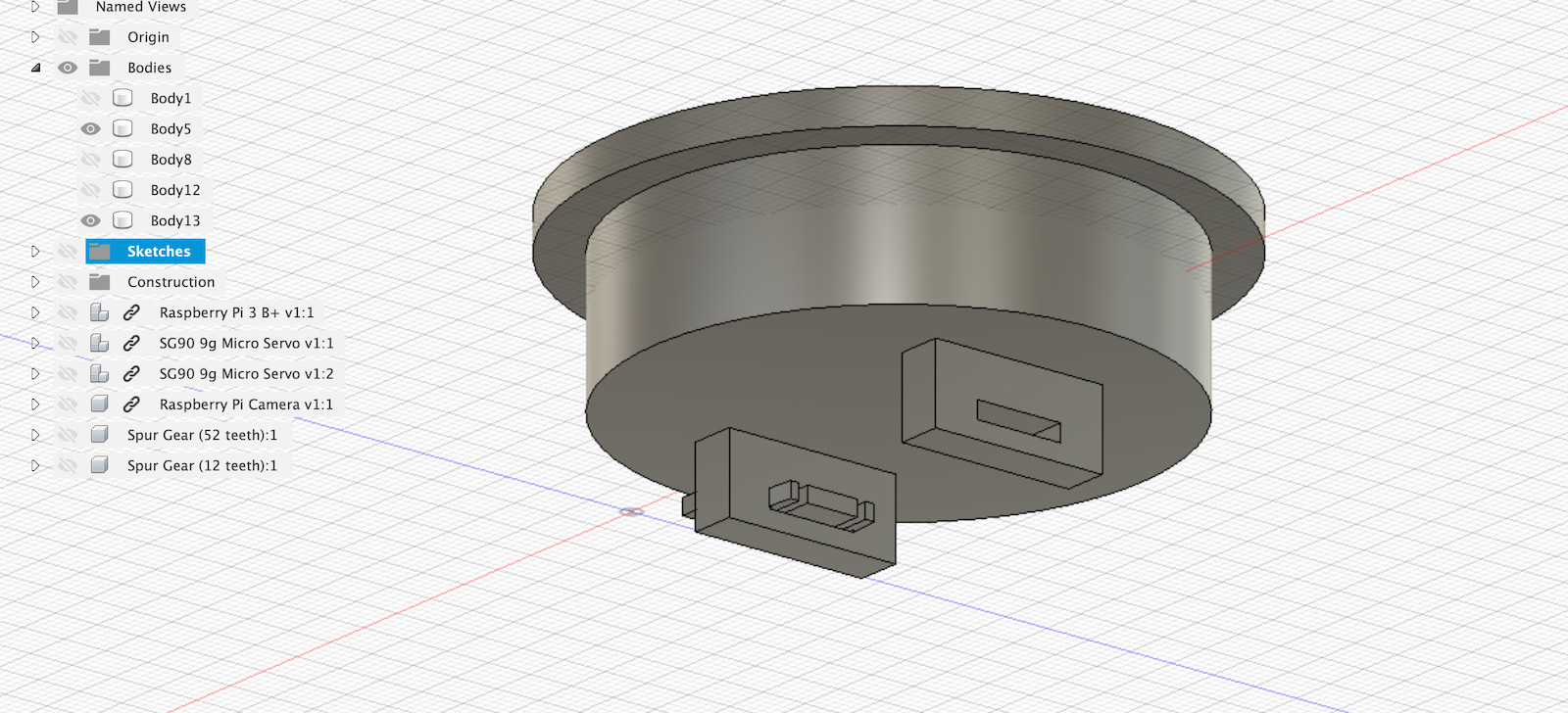
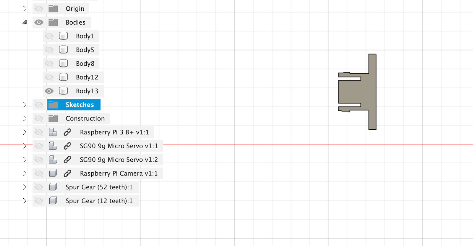
The chaft locking the Raspberry Pi support
This way only the cable that will power the raspberry needs to have some play so that the YAW/rotation of the Raspberry isn’t affected.
The rotation axis will be working for now without any bearings to reduce the friction because there isn’t a lot of weight to support and the rotation isn’t continuous. But, if needed, i can redesign to accomodate some metal rings and bearing to reduce friction or eventually design to use some bearings.
Note: This design is also good in a way that if you want to use other hardware, you just need to redesign the support with same press-fit locking feature to attach for example bigger camera (The base of the spidercam will be the same).

Exploded view
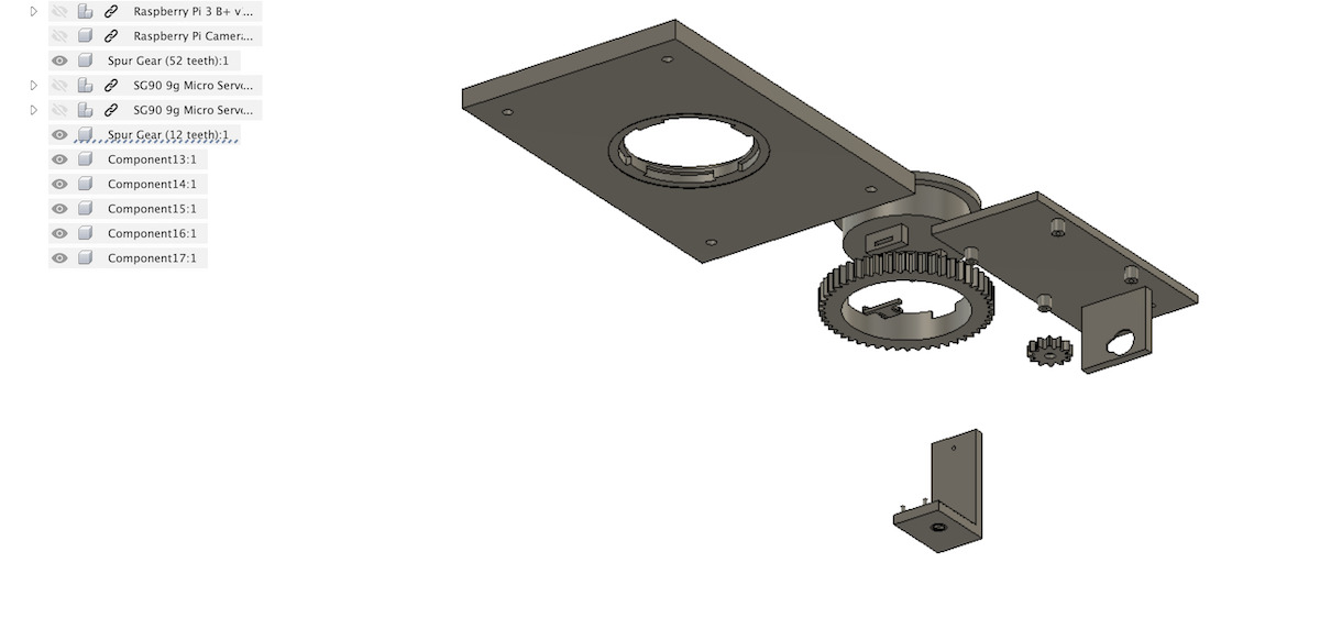
All the parts 3d printed. This was the final design for this week assignment that served as base for Machine Desin week.
Spur gears
To design the Spur Gears in Fusion 360 i used the “Spur Gear” script. To access it you need to click on “Tools” -> “ADD-INS” -> “Scripts and Add-Ins…”
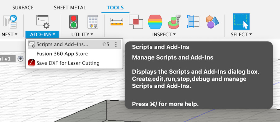
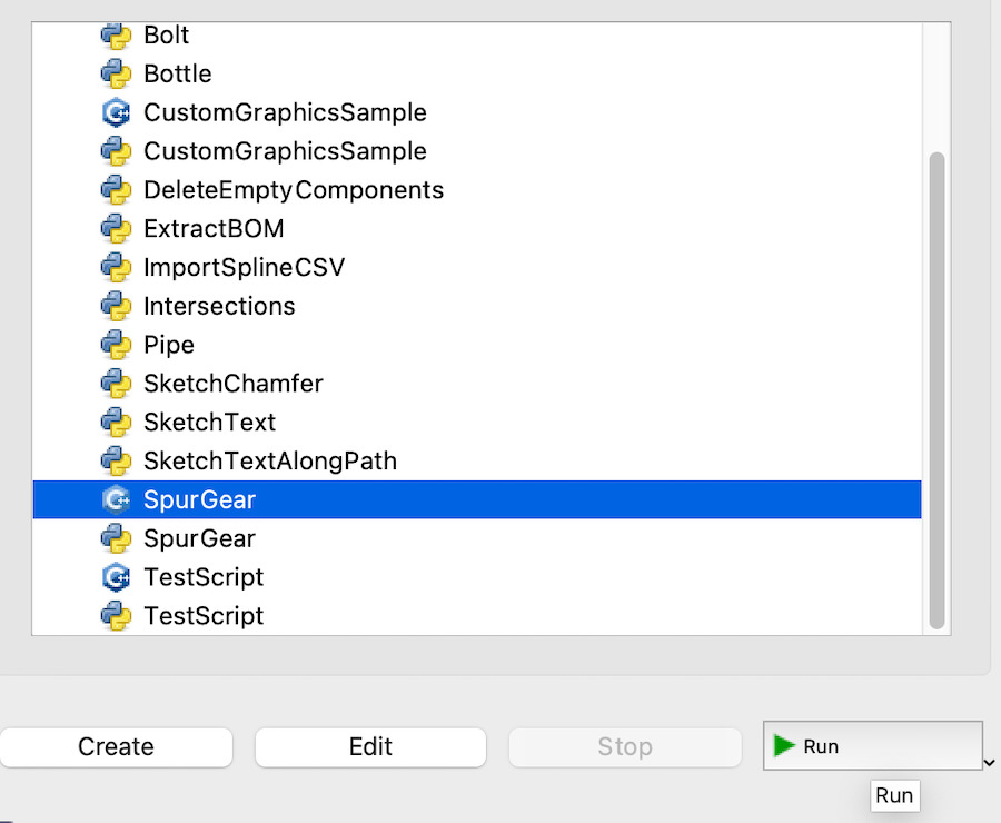
then select the script “SpurGear” and click “Run” button.
You will see the plugin interface to configure the parameters
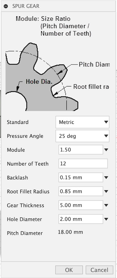
This is the config for the small 12 teeth spur gear that connects directly to the micro servo and rotates the Raspberry Pi support by moving along the 52 teeth Spur Gear that is connected to the base plate.
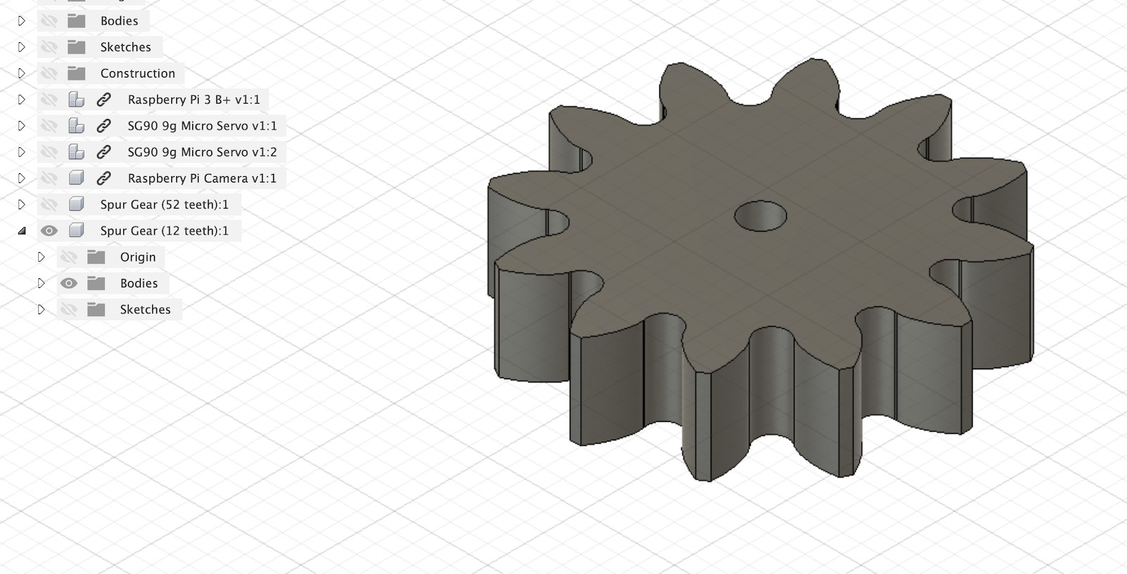
The plugin allows to design spur gears with good rolling action and small friction. For more information about spur gear design check Guerrilla guide to CNC machining, mold making, and resin casting: 6.2 Creating spur gears.
Files
Links
- Spur Gears
- Guerrilla guide to CNC machining, mold making, and resin casting: 6.2 Creating spur gears
- Ting Kok Eng (2020 FabAcademy, Mechanical Design & Machine Building) for spur gears design with Fusion 360 add-in.
- Create Custom 3D Printable Gears in Fusion 360 | Practical Prints #1
- Raspberry Pi 3 b+ (3D model)
- SG90 9g micro servo