4. Computer controlled cutting
Laser Cutting
Learning outcomes
- Demonstrate and describe parametric 2D modelling processes
- Identify and explain processes involved in using the laser cutter.
- Develop, evaluate and construct the final prototype
Have you
- Explained how you parametrically designed your files
- Shown how you made your press-fit kit
- Included your design files and photos of your finished project
What is a laser ?
Laser or Light Amplification by Stimulated Emission of Radiation in a simple way is a machine that can emit light. This light is bounced back and forth by mirrors while passing by a optical gain medium generating more light (“light amplification”). This process results in a more strong light beam we call Laser. This laser then can be very focused in a tiny point or unfocused to cover a bigger area depending on the final use.
The optic element of the laser determines the laser profile. It can be used to burn, melt, evaporate or blast material.
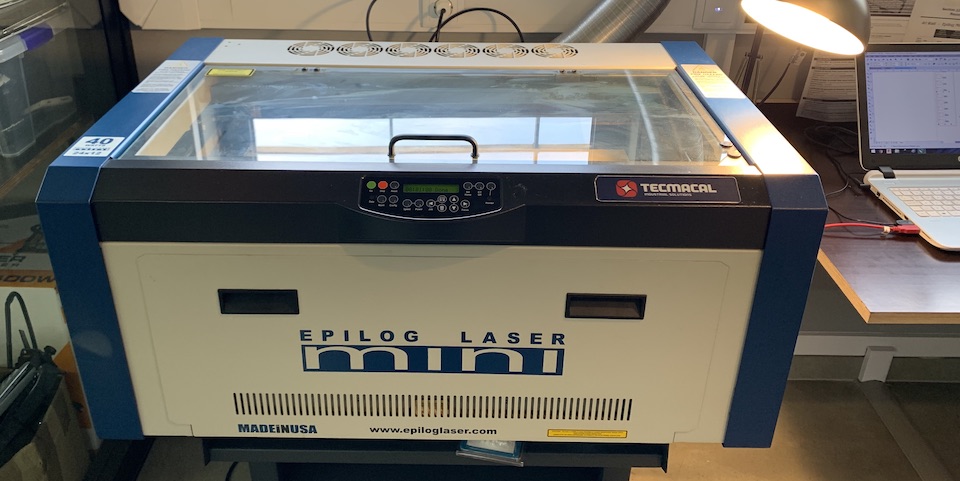
FabLab laser cutter
FCT FabLab has a Epilog Mini 24 laser cutter with 40watts of power. This machine can engrave in a area of 610 x 305 mm and a material max thickness of 140 mm. The source of the laser is a digitally controlled, air-cooled CO2 laser tube.
The size of the machine 876 x 660 x 406 mm and weight 41 kg (55 kg) w/stand. It has a ventilation system that can exhaust to the outside or internal filter system 595-680 m3/hr.
Material Compatibility
| Material | Engrave | Cut |
|---|---|---|
| Wood | x | x |
| Acrylic | x | x |
| Fabric | x | x |
| Glass | x | |
| Coated Metals | x | |
| Ceramic | x | |
| Delrin | x | x |
| Cloth | x | x |
| Leather | x | x |
| Marble | x | |
| Matte Board | x | x |
| Melamine | x | x |
| Mother of Pearl | x | x |
| Paper | x | x |
| Mylar | x | x |
| Pressboard | x | x |
| Rubber | x | x |
| Wood Veneer | x | x |
| Fiberglass | x | x |
| Painted Metals | x | |
| Tile | x | |
| Plastic | x | x |
| Cork | x | x |
| Corian | x | x |
| Anodized Aluminum | x |
Security
- Air flow is ESSENTIAL for cutting and also for SECURITY reasons.
- DO NOT OPEN laser machine while it’s working!
- After laser job is finished, WAIT around 1min for any gases, smoke could be exhausted.
- ATTENTION to used materials, like PVC. The laser machine isn’t fully watertight, so some smell, gases, smoke could get out into the fab lab.
- Take care of laser maintenance.
Links
Group assignment
Characterize your lasercutter’s focus, power, speed, rate, kerf, and joint clearance
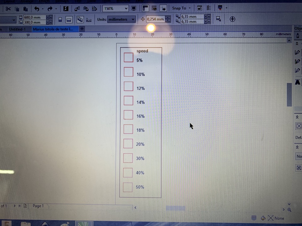
Material test scale
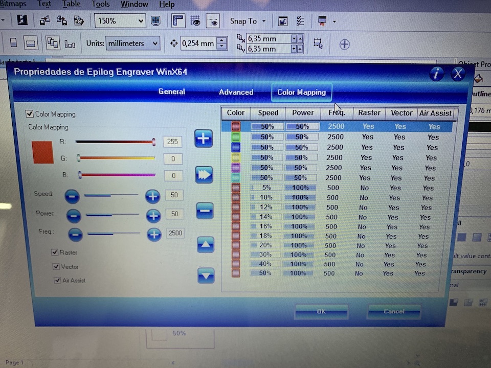
Corel parameters for test scale
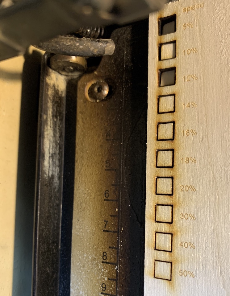
Laser cut test
So from Epilog laser manual states rate of 500 for most organic materials, so that was the value we used. For the test in Corel it was configured power to 100%, so 40W, the theoretical maximum this laser can do (we don’t have a way to measure the laser power and confirm the 40W). Then for each RGB color values it was set a speed percentage from 5% up to 50%.
The best configuration to fully cut the wood without burning too much the material is with:
- Power 100%
- Speed 18%
- Rate 500
From the cutted squares and by using a Vernier Caliper, we managed to measure the laser kerf, value of 0.15mm.
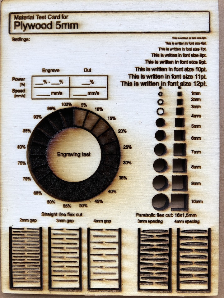
Material test card
We also did a laser material test card with plywood, mainly to test raster and have in same place some living hinges test examples.
Individual assignments
Have designed the press-kit presented on the class as a way to introduce myself to the laser cutter.
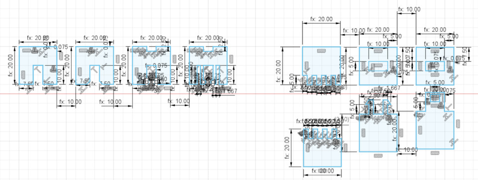
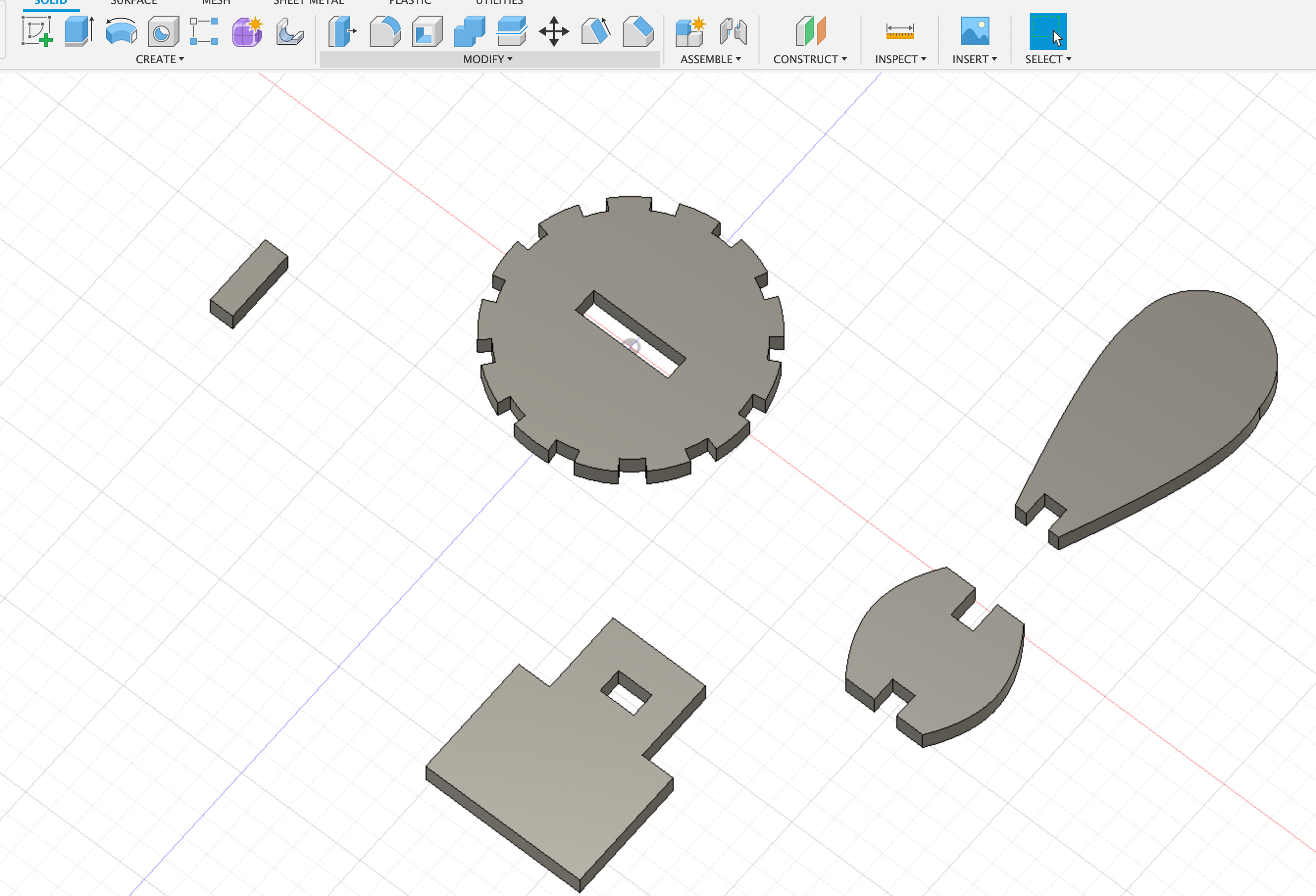
From academy FreeCad joints
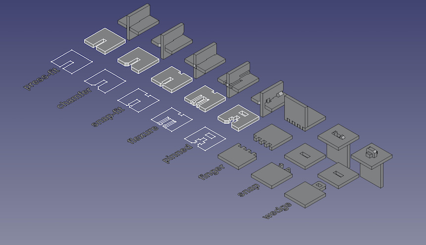
design into Fusion 360
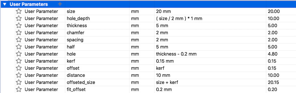
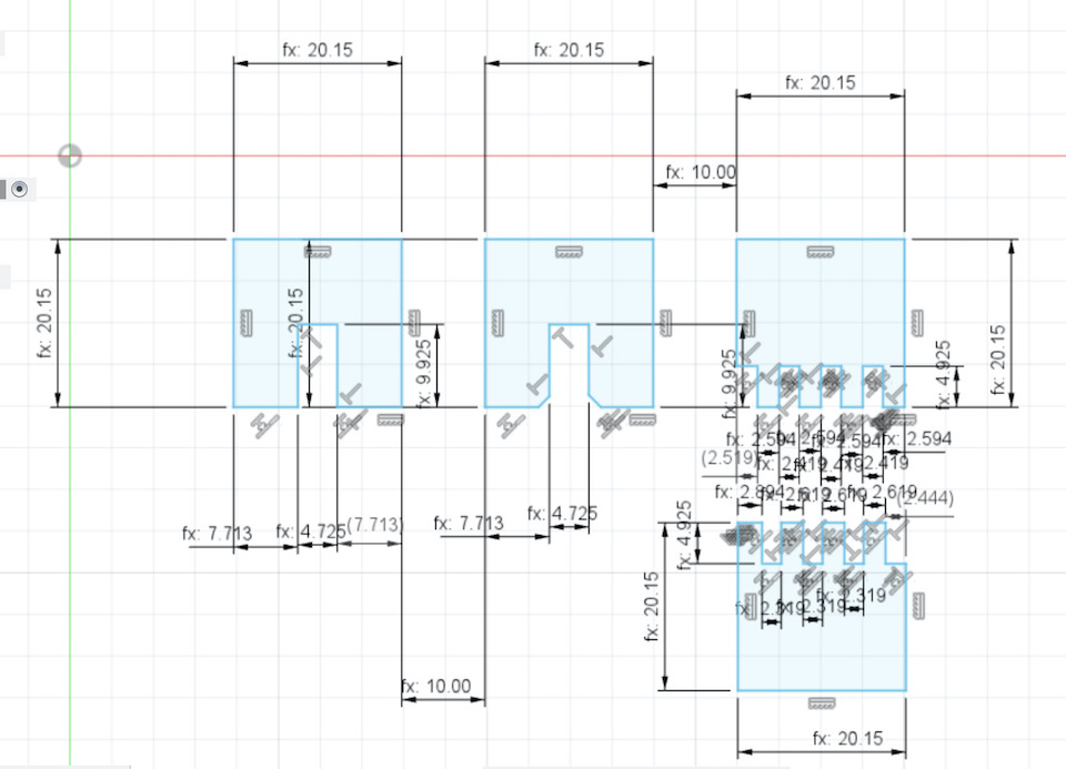
Defined the following params to be used with constraints
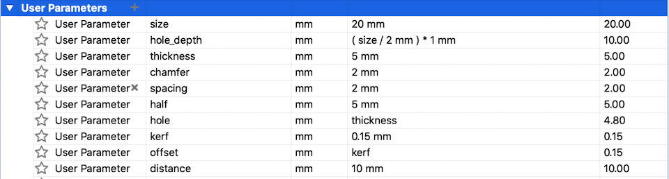
Tried to apply constraints so that i could change material thickness, size and kerf during the cutting tests.
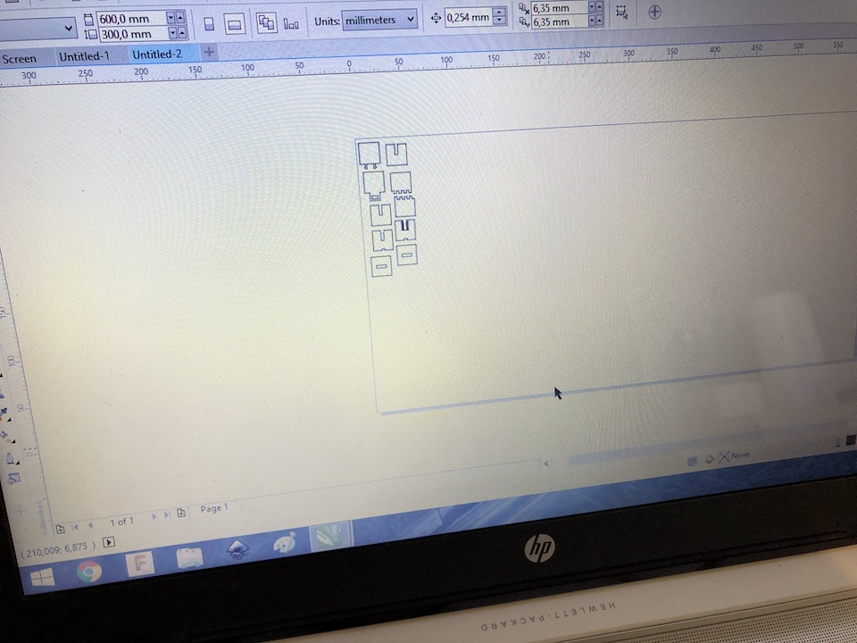
From the sketch i exported a DXF file and used it in the laser cutter computer with corel to prepare and make the cut.
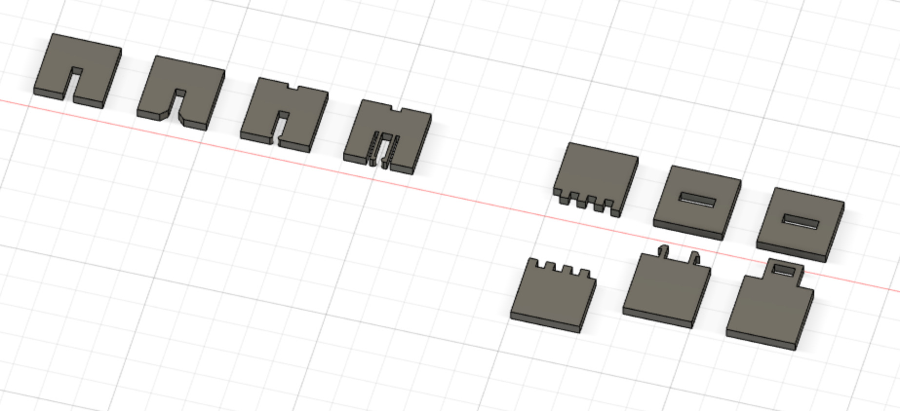
On the 1st try things didn’t went properly as planned, needed to adjust the thickness of material, some contraints and sketch itself. But on second try after adjustments it started to show some results.
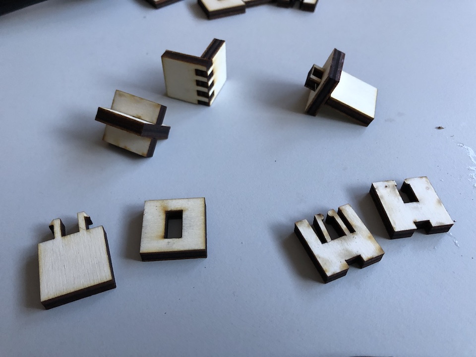
note: Because of the material, the flexure and snap joints aren’t working, they break.
Improved press-fit and finger joints
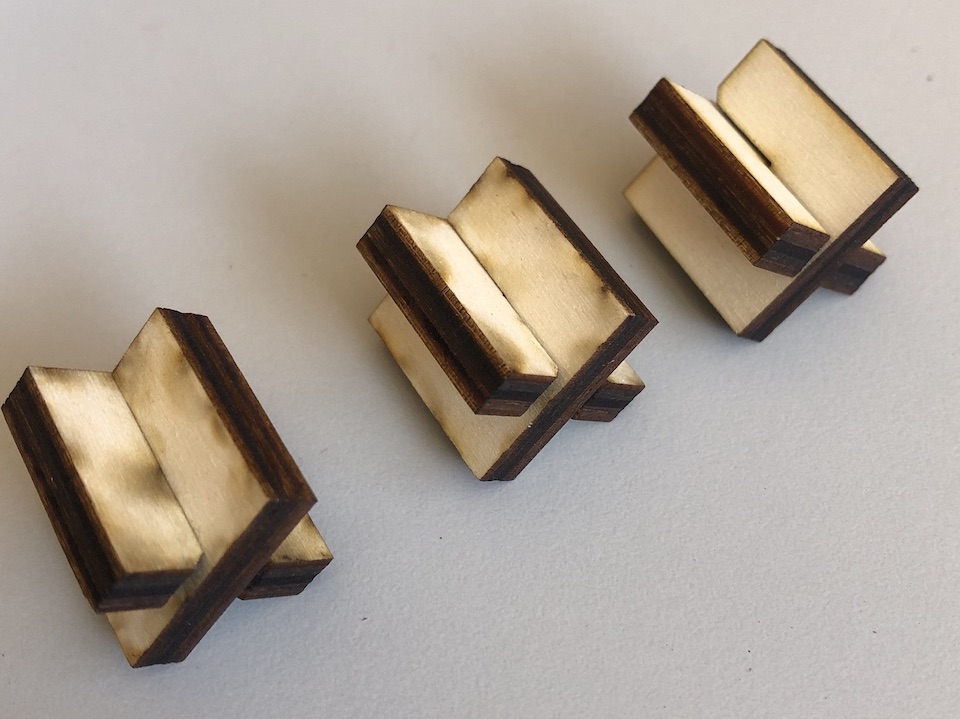
After testing laser and doing most of the joints i tried to improve them, by having really tight/high friction fit. So i redesign and parameterize press-fit and finger joints again.
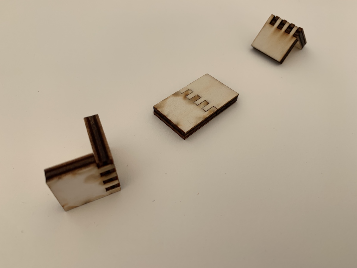
So the final result for the press-fit was really good, tight, no movement as you can see in the below images, piece on the left.
The final finger joint became also good, tight, no movement, you need to pull away with a good amout of force to pull pieces apart. See image below, piece at the bottom.
File: Fusion 360 press-fit_kit.f3d
Small flower construction kit (press-fit)
Based on the previous press-fit kit exercise i designed a small flower press-fit kit.
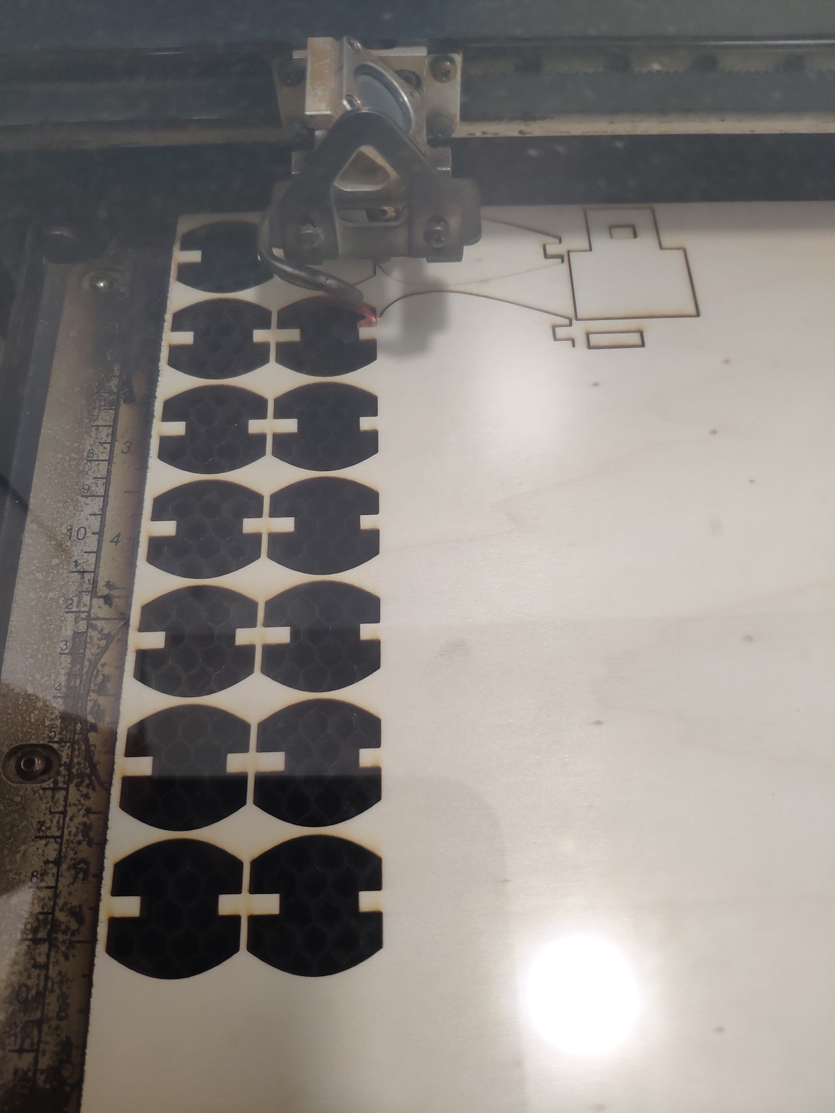
Laser cutting the plywood.
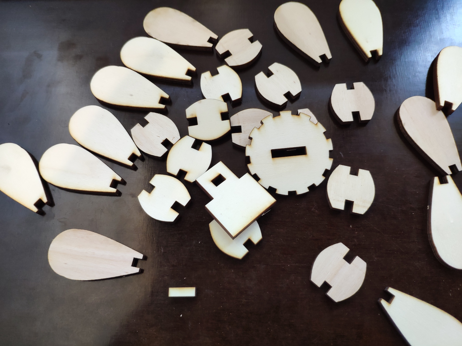
The press-fit kit
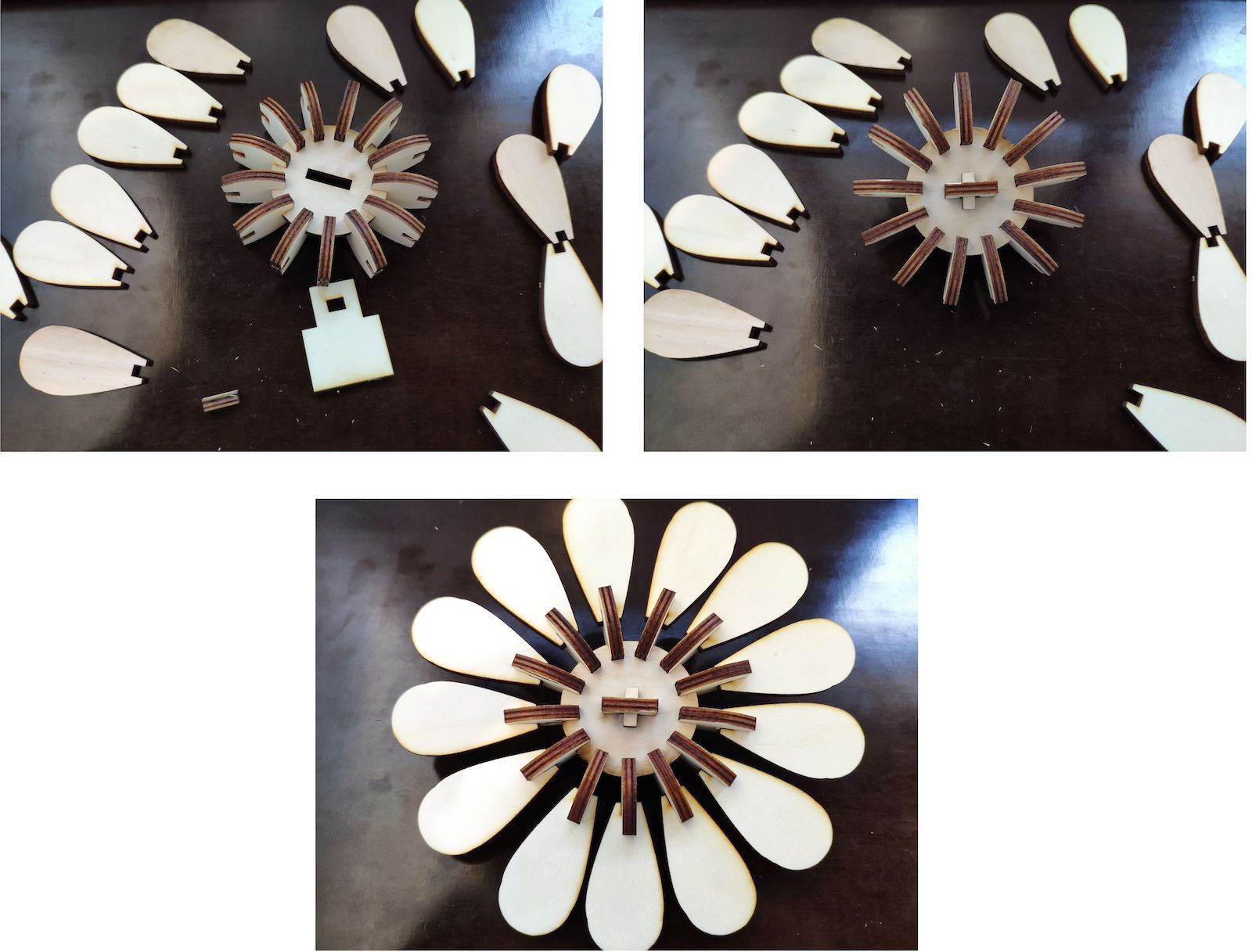
Flower assembling
Files:
- Fusion 360 flower-press-fit_kit.f3d
- DXF files flower-press-fit_kit_dxf.zip
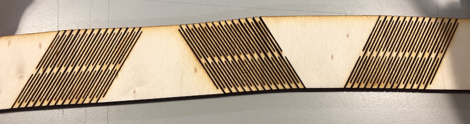
Living Hinges
To explore living hinges i tried to learn and make a Mobius strip design.
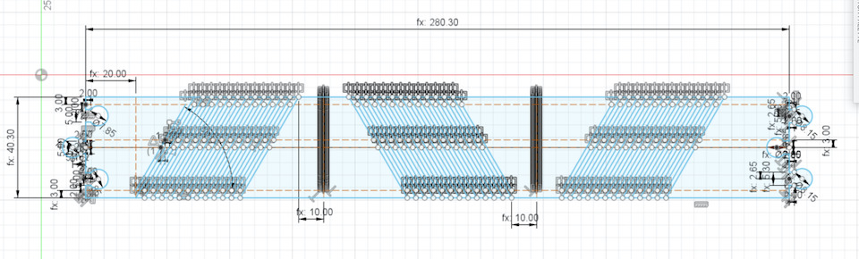
Design
- length: 280mm
- height: 40mm
- material_width: 5mm
- kerf: 0.15mm
- joint_radius: 8mm
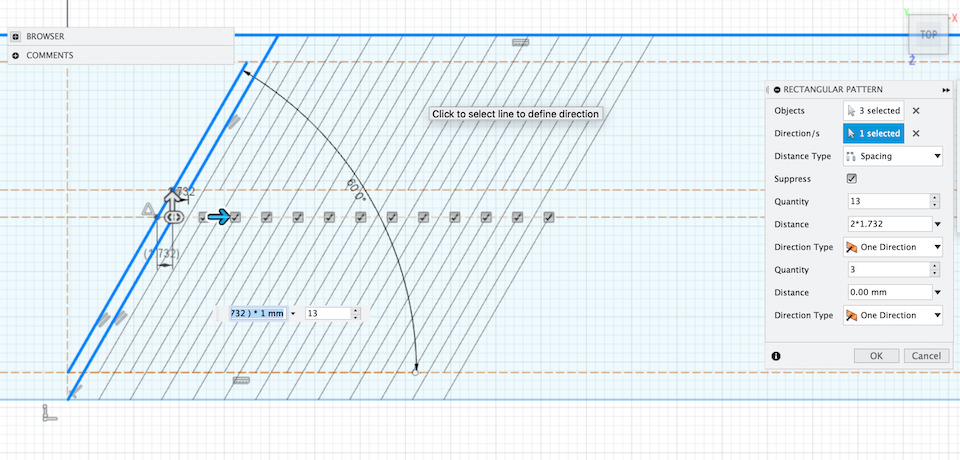
Designed the straight line pattern beginning and learned how to use the Rectangular Pattern tool.
After clicking the tool, selected the 3 lines that make the straight line pattern. Then in Rectangular Pattern options, clicked to set direction and selected the top horizontal line.
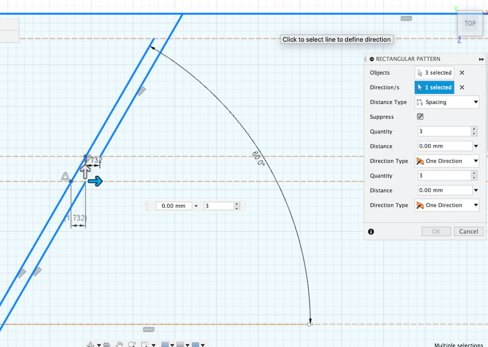
Set distance type to Spacing, Quantity 13 and Distance to 2 * (distance between straight lines pattern) and pressed ok.
After this step created a construction line (10mm in front of straight line pattern) to use with the Mirror tool, something i also tested for the 1st time in fusion.
So after clicking in the Mirror tool, and selecting the straight line patterns (press shift to select the lines in the bottom part of the pattern)
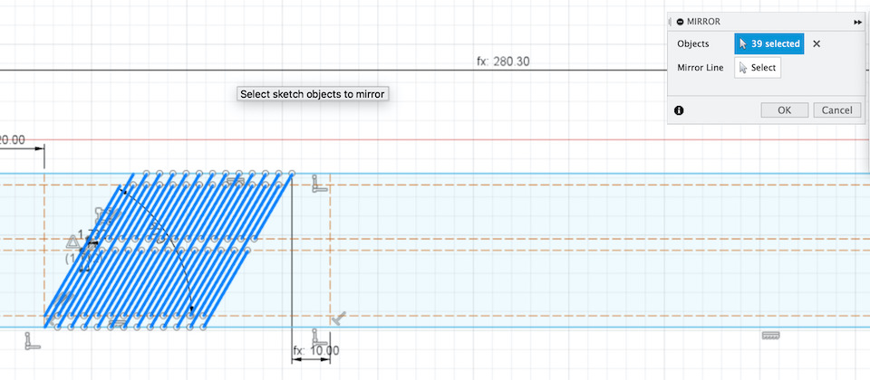
i clicked the “select” for mirror option and clicked in the construction line, showing how it would look the mirrored pattern. At this point i clicked “ok” in the Mirror box.
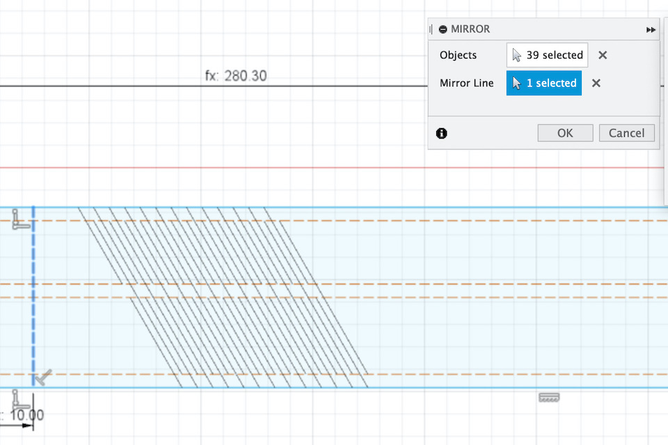
Repeated the process one more time and created the puzzle like locking mechanism.
The result after cutting in the laser
And the final result, think that was a good test for this live hinge :)
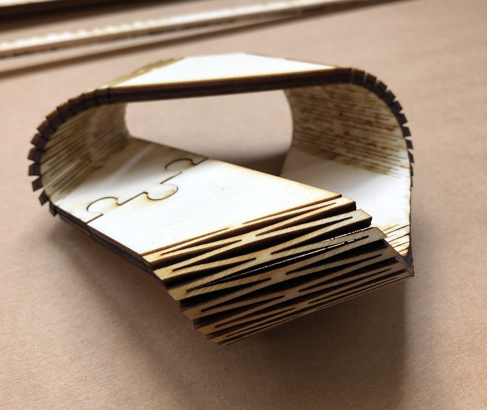
File: Fusion 360 mobius_strip.f3d
Links
Vinyl Cutting
Learning outcomes
- Identify and explain processes involved in using this machine.
- Design and create the final object
Have you?
- Explained how you drew your files
- [x] Shown how you made your vinyl project
- Included your design files and photos of your finished project
Drawing for vinyl cutter
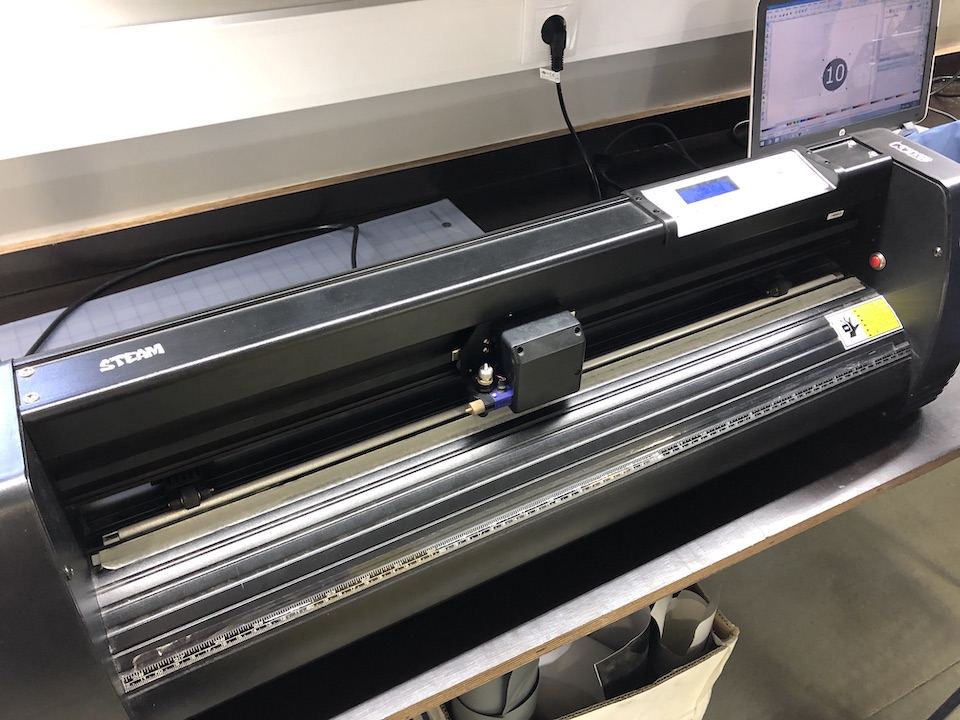
The vinyl cutter available on the FCT FabLab is a Roland MH 721. Some of the cutter characteristics:
- Standard blade
- Drived by stepper motors
- Connects to pc via USB
- Max cutting length 243cm
- Max cutting width: 62cm
- Max pressure: 350grams
- Max speed: 121cm/s
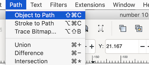
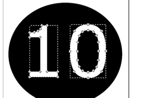
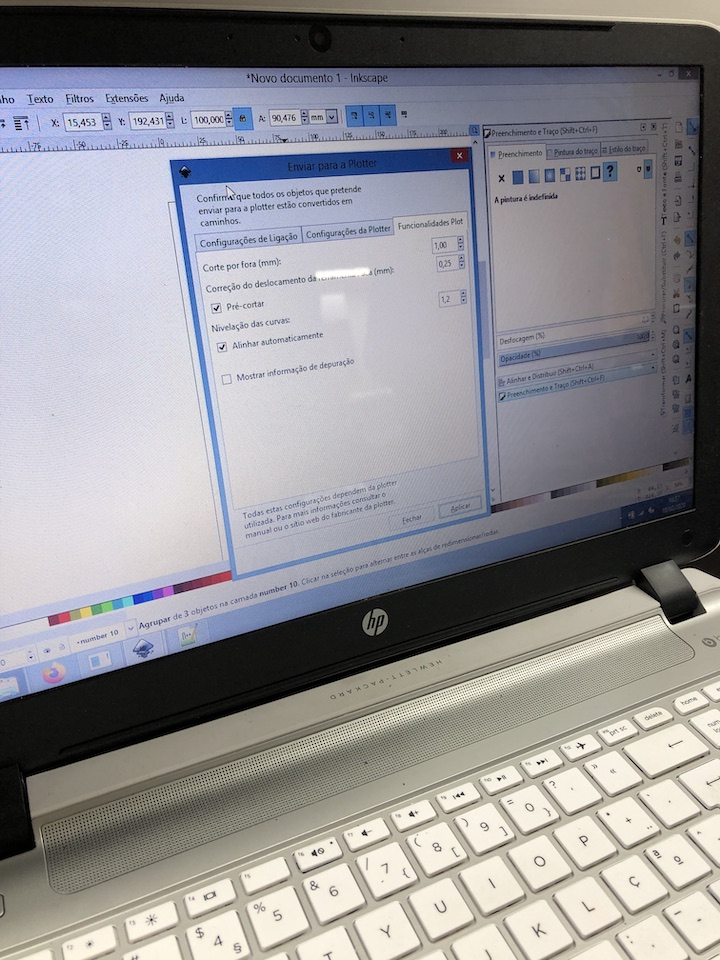
For this task i choose to make a simple number sticker. Used Inkscape to make the drawing so started by creating a new file on Inkscape and adding a text with number 10. Changed the font color to white then added a black circle and moved it to the bottom so that the previous added number showed on top of the black circle . The idea is to have a vinyl dot with a number 10 inside.
In the end selected the 2 objects and converted the objects to path, mainly because text objects need to be converted to path so that the vinyl cutter know what/where to cut.
For the vinyl cutter the print process was straight forward.
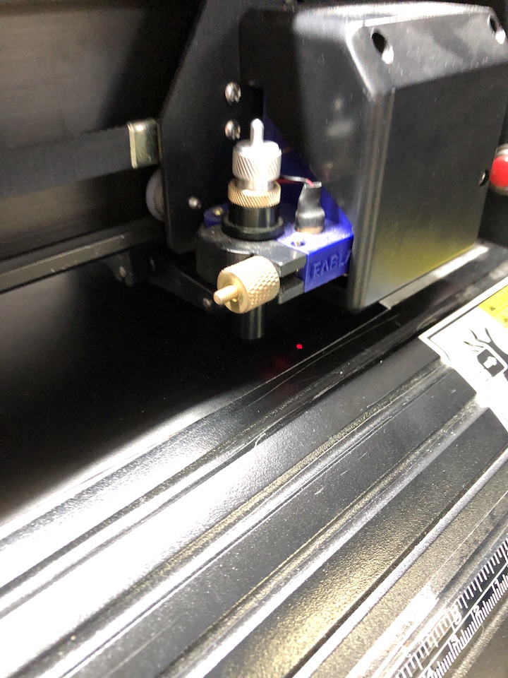
Vinyl was added and locked into the Roland MH 721 cutter.
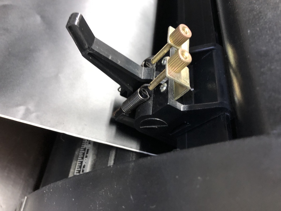
Set the home point
Checked plotter settings, just to confirm usb port in use and what could be changed in driver.
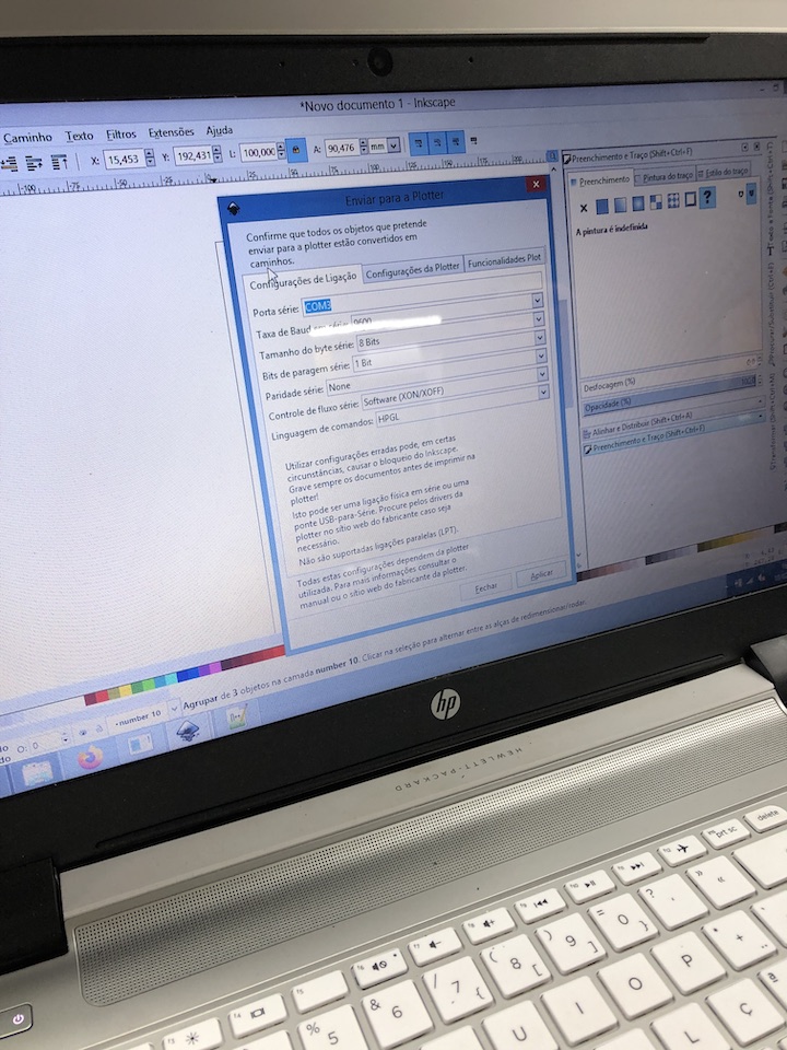
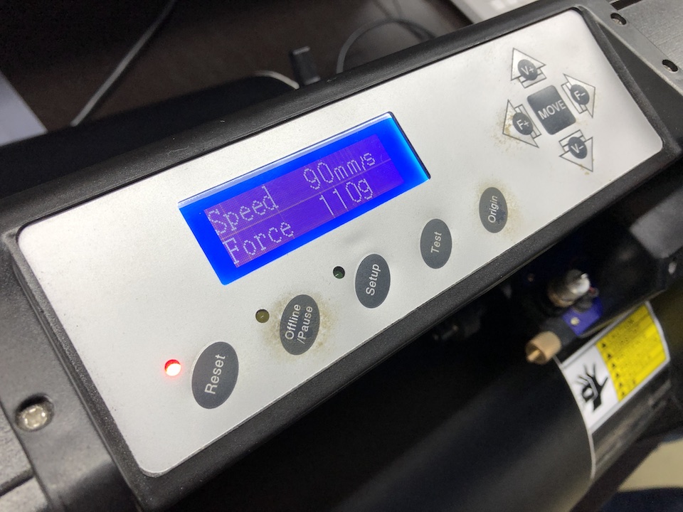
Speed was set to 90m/s and force 110g
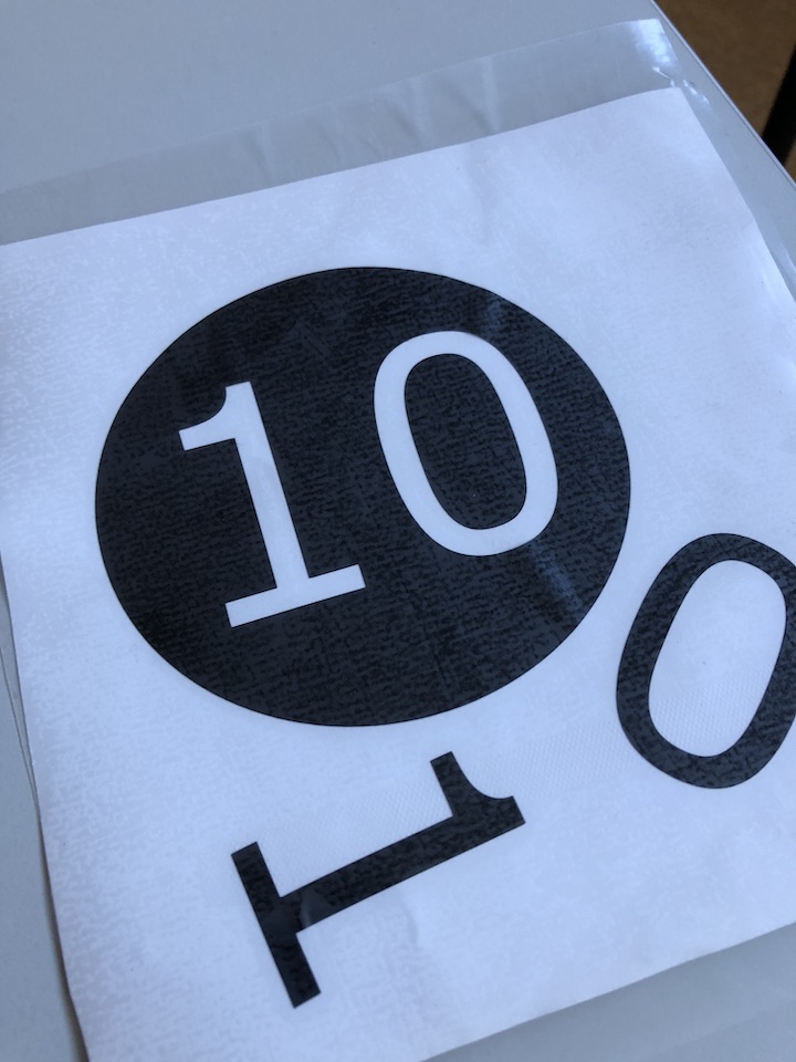
And started the cut process. Then with the help of transfer plastic/tape, transfered the vinyl by lifting the cutted parts with the tape and placing at target sheet. The transfer tape allows to move and apply the vinyl without damaging it.
The final result.
File: Inkscape number_10.svg