14. Networking and communications
Learning outcomes
- Demonstrate workflows used in network design
- Implement and interpret networking protocols and/or communication protocols
Have you?
- Linked to the group assignment page
- Documented your project.
- Documented what you have learned from implementing networking and/or communication protocols
- Explained the programming process/es you used.
- Outlined problems and how you fixed them
- Included design files (or linked to where they are located if you are using a board you have designed and fabricated earlier) and original code.
Group assignment
- Send a message between two projects
For the group documentation, please check group assignment page here: Networking and communications (Group page)
Individual assignment
- design, build, and connect wired or wireless node(s) with network or bus addresses
For this week assignment i choose to use Inter-Integrated Circuit (I2C) to create a wired connection between my 2 boards. Choosed I2C because it looks more simple (1 master connected to multiple slaves without the need to have 1 connection for each slave) to create a network than Serial Peripheral Interface and allows to have all connected nodes reading/writing without one being always the master node (I2C can be used with multi-master but for this week i’m going to use as single master <-> multiple slaves). I never used this protocol for communication on any software i developed, so this is a good excuse to learn. I’m also planning to use it on my final project to connect different PCB modules (Drive, Sensor and Communication boards), seams better suited for this.
I2C works by having a two wire bus with resistors pulling-up.
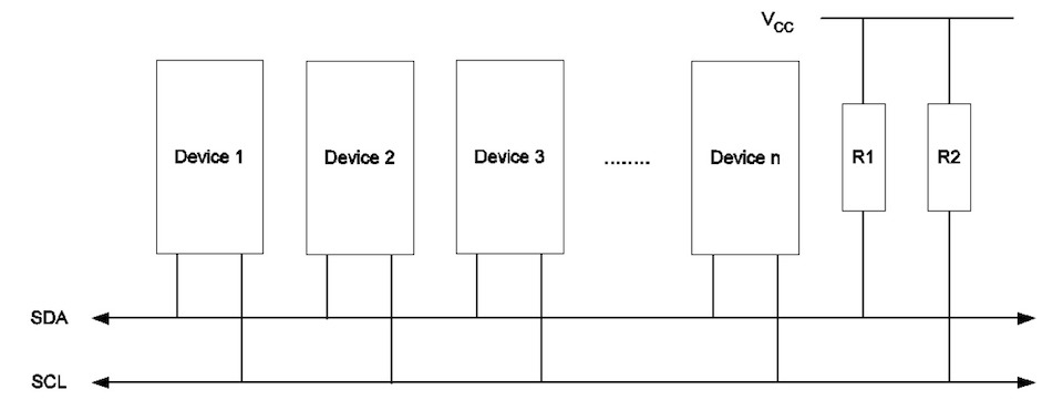
The protocol is relatively simple to understand.
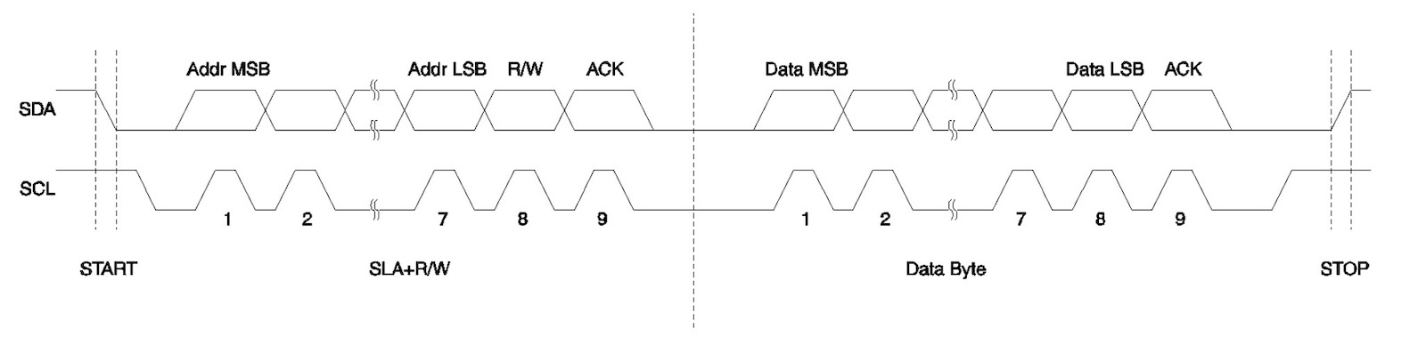
There is a START condition that allows connected nodes to detect start of communication. Because lines are up, the START condition is when Serial Data (SDA) goes down while Serial Clock (SCL) is up (note: clock is managed by master). Then communication happens in a form of 8-bits. After START conditions the next 7-bits represent the slave address and last 8th bit is the Data Direction (0 -> master writes to slave; 1 -> master reads from slave). After this exchange data can be written/readed between master and slave being acknowledge after every 8-bits by receiver (ACK, while SCL is up, SDA is holded down by receiver node and “released” on clock down). After communication a STOP condition is triggered by SDA changing from LOW to HIGH while SCL is HIGH. (For more information check Using the TWI Module as I2C Master and Using the TWI Module as I2C Slave).
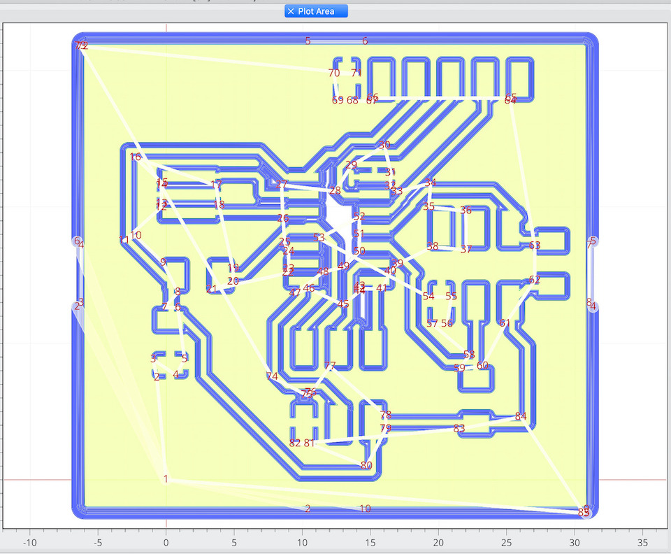
So based on the previous Eagle design from 7. Electronics design week, made changes to have pins for I2C.
| Components | Quantity |
|---|---|
| ATtiny44A-SU | 1 |
| ECS-CR2-20.00-B-TR (20Mhz Resonator) | 1 |
| R 10K ohm SMD 1206 | 3 |
| Capacitor 1uF SMD | 1 |
| Headers 2x3 | 2 |
| FTDI header | 1 |
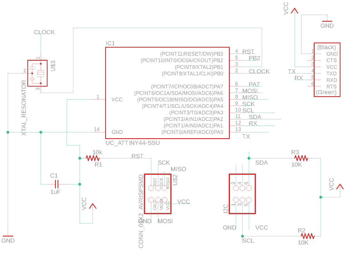
Board schema
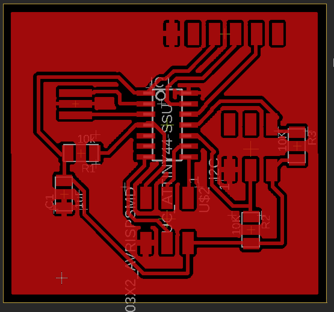
FlatCAM Isolation path
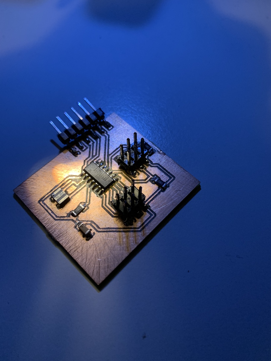
Milled PCB
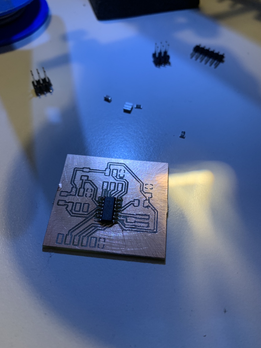
and stuffed
File: Eagle I2C_HelloBoard.zip
The ISP pins will be used to program the board as usual and the I2C pins will be used to communicate with other nodes.
Links
- I2C Bus Specification
- Using the TWI Module as I2C Master
- Using the TWI Module as I2C Slave
- Selecting Between I2C and SPI for Your Project
Serial bus - asynchronous
Before going into I2C i tested the communication between board using Serial bus (asynchronous). Started by using Neil’s hello.bus.45.c and hello.bus.45.make example and made changes. Re-used by ATtiny boards for this example so one of the boards connected to the computer via serial was configured to have other 2 pins as TX/RX to communicate with nodes. This one acted as a bridge because it reads from PC serial and writes into nodes serial bus (and vice-versa).
So updated the code to have the correct led pin and added the pins for network serial RX/TX.
#define led_port PORTA
#define led_direction DDRA
#define led_pin (1 << PA2)

#define serial_port PORTA
#define serial_direction DDRA
#define serial_pins PINA
#define serial_pin_in (1 << PA0)
#define serial_pin_out (1 << PA1)

#define network_serial_pin_in (1 << PA6)
#define network_serial_pin_out (1 << PA5)

#define node_id '0'
Because this node ‘0’ will act as bridge, modified also the code inside main().
 clear(led_port, led_pin);
   output(led_direction, led_pin);

   //
   // main loop
   //
   while (1) {
    get_char(&serial_pins, serial_pin_in, &chr);
    flash();
    if (chr == node_id) {
        output(serial_direction, serial_pin_out);
        static const char message[] PROGMEM = "node ";
        put_string(&serial_port, serial_pin_out, (PGM_P) message);
        put_char(&serial_port, serial_pin_out, chr);
        put_char(&serial_port, serial_pin_out, 10); // new line
        led_delay();
        flash();
        input(serial_direction, serial_pin_out);
    }else{
        put_string(&serial_port, serial_pin_out, "Unknown\n");
    }
    output(serial_direction, network_serial_pin_out);
    put_char(&serial_port, network_serial_pin_out, chr);
    input(serial_direction, network_serial_pin_out);
  }
This allows to initialize led and inside the while() any char read from serial between PC and PCB is also written into network serial to connected nodes.
On this example i’m using by boards from previous weeks. Like on Neil’s example, each board will flash() on any communication via serial and flash() twice if the node id is the same sent via serial.
For the node the code the changes are small. Making sure led pin is correct and node_id is different.
#define led_port PORTA
#define led_direction DDRA
#define led_pin (1 << PA3)

#define serial_port PORTA
#define serial_direction DDRA
#define serial_pins PINA
#define serial_pin_in (1 << PA5)
#define serial_pin_out (1 << PA6)

#define node_id '1'
After connecting the two boards and testing it the test example was working.
Files:
- Bridge (id: 0): hello.bus.bridge.44.c, hello.bus.bridge.44.make
- Node (id: 1): hello.bus.node.44.c, hello.bus.node.44.make
Serial bus - I2C
Now for I2C communication. Have used I2C already to read sensors for 11. Input devices week, by starting with Neil’s code example hello.ADXL343. This is a master example, so for this week have decided to implement the a slave side. From the datasheets i know that microcontrollers have TWI and USI that can be used to implement slave, but to learn I2C, i decided to follow the “bit-bang” software implementation.
To help to debug the SDA and SCL signals bought a simple and pocket-size handheld digital oscilloscope (DSO Nano V3).
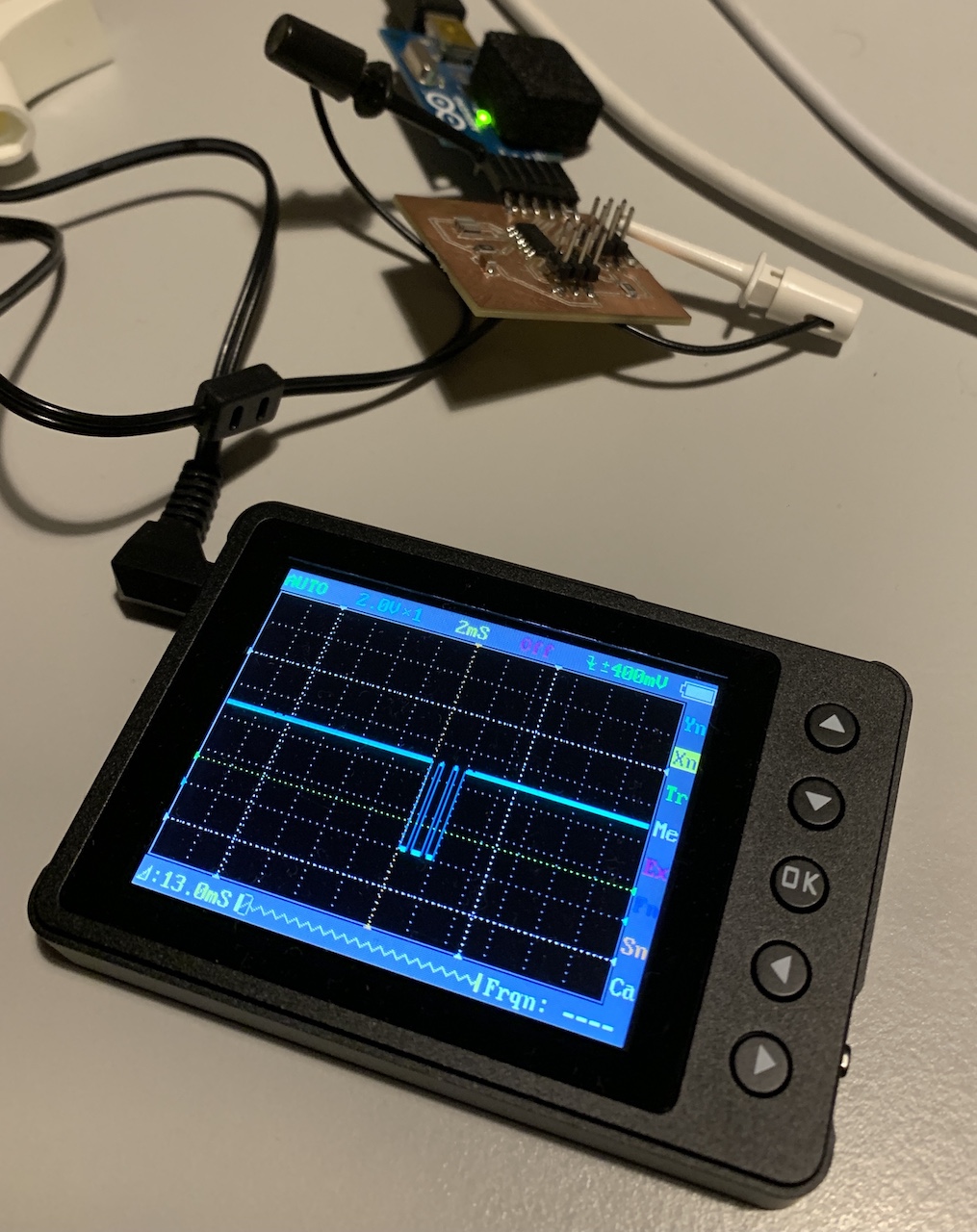
This helped to have a more clear idea of what was happening, pull-ups, signals high and low to slowly implement the I2C slave.
Started by having master just by writing 1 byte of data into a slave
data[0] = 0xC0; // device ID register
ret = I2C_master_write(data,1,the_slave_address);
while on the slave side was implementing the changes to read the 8 bits: 7bit of slave address + 1bit of master read/write. This took some time to understand and get it right but eventually managed to read the information on on the slave side. The changes for this to work were mainly done in I2C_slave_read_byte(). So slave needs to read each bit when SCL is up.
void I2C_slave_read_byte(unsigned char* data, unsigned char index, unsigned char nbytes) {
  //
  // slave read I2C byte
  //
  unsigned char byte,bit;
  byte = 0;
  //
  // loop over bits
  //
  for (bit = 0; bit < 8; ++bit)  {
    while(pin_test(SCL_pins,SCL_pin) == 0);

    if (pin_test(SDA_pins,SDA_pin) != 0){
      byte |= (1 << (7-bit));
    }
    while(pin_test(SCL_pins,SCL_pin) != 0);
  }

  data[index] = byte;

}
Then to allow to read n bytes, the I2C_slave_read() was also updated following same changes done in I2C_slave_read_byte(). On this method an ACK is sent back after reading each 8bits, so that master could continue and send the data (tested this only with writing from master to slave).
char I2C_slave_read(unsigned char* data, unsigned char nbytes, unsigned char slave_address) {
  //
  // I2C slave read
  //
  unsigned char index, slave_address_read;

  //
  // receive slave address
  //
  I2C_slave_read_byte(&slave_address_read,0,1);

  if (slave_address_read != slave_address){
    return 1;
  }

  // done, send ACK
  //
  while(pin_test(SCL_pins,SCL_pin) == 0);
  while(pin_test(SDA_pins,SDA_pin) == 0);
  SDA_write(0);
  while(pin_test(SCL_pins,SCL_pin) != 0);
  SDA_write(1);

  //
  // loop over bytes
  //
  for (index = 0; index < nbytes; ++index)
    I2C_slave_read_byte(data,index,nbytes);
    // done, send ACK
    //
    while(pin_test(SCL_pins,SCL_pin) == 0);
    while(pin_test(SDA_pins,SDA_pin) == 0);
    SDA_write(0);
    while(pin_test(SCL_pins,SCL_pin) != 0);
    SDA_write(1);

  return 0;
}
This code was done after some bumps and signal debuging and baby steps to understand I2C. Osciloscope was also andy to know and confirm the slave SDA pull-down for ACK.
Once this was done the rest of the code was changed so that the master board could send the same 0xC0 data byte to selected slave. For the example have programmed 2 slave boards with 0x21 and 0x22 addresses.
while (1) {

    //
    // Read device ID
    //

    get_char(&serial_pins, serial_pin_in, &i);

    // write into serial console the read ID
    put_char(&serial_port, serial_pin_out, i);
    put_char(&serial_port, serial_pin_out, 10);

    switch(i){
      case '2':
        the_slave_address = 0x22;
        break;
      case '1':
        the_slave_address = 0x21;
        break;
      default:
        the_slave_address = 0x20;
    }

    I2C_init();

    data[0] = 0xC0; // device ID register
    ret = I2C_master_write(data,1,the_slave_address);

    _delay_us(10000);

  }
on slave side, the slave loops waiting for START condition, then tries to read 1 byte. In case it reads 1 byte addressed to himself, it flashes a led.
while (1) {
    //
    // read and send data
    //
    if((pin_test(SCL_pins,SCL_pin) != 0) && (pin_test(SDA_pins,SDA_pin) != 0)){

      while(pin_test(SCL_pins,SCL_pin) != 0){
        if(pin_test(SDA_pins,SDA_pin) == 0){

          ret = I2C_slave_read(data,1, I2C_slave_address);

          if((ret == 0) && (data[0] == 0xC0)){
            flash();
          } else {
            break;
          }
        }
      }

    }
  }
The video showing 1 and 2 being inputed to select the 1st or 2nd board to flash led. It’s now perfect all the time, seams there are some sync lost sometimes, but it’s working :)
Files:
- I2C Master: hello.i2c.master.44.c, hello.i2c.master.44.make
- I2C Slave: hello.i2c.slave.44.c, hello.i2c.slave.44.make
Slave configuration
To program the slaves i have used same code and the USE_PCB_* macro selected at programming time what ID was being used to compile and program the slave. This allowed also to configure the correct pin for led on each slave PCB.
hello.i2c.slave.44.c configuration:
// #define USE_PCB_21 1
#define USE_PCB_22 1


// led + button pcb
#ifdef USE_PCB_21
#define led_port PORTA
#define led_direction DDRA
#define led_pin (1 << PA2)
#define I2C_slave_address 0x21 // ATtiny pcb for button and led
#endif

// step response pcb
#ifdef USE_PCB_22
#define led_port PORTA
#define led_direction DDRA
#define led_pin (1 << PA3)
#define I2C_slave_address 0x22 // ATtiny44 pcb for step response
#endif
Links
- I2C-bus specification and user manual
- Introduction to I²C and SPI protocols
- I2C
- Serial Peripheral Interface
- ATtiny44A Complete datasheet
- Atmel AVR 8-bit Microcontroller AVR151: Setup and Use of the SPI
- Practical I2C: Introduction, Implementation and Troubleshooting
Networking with ESP8266 (Internet Protocols, HTTP, IPv4, RF)
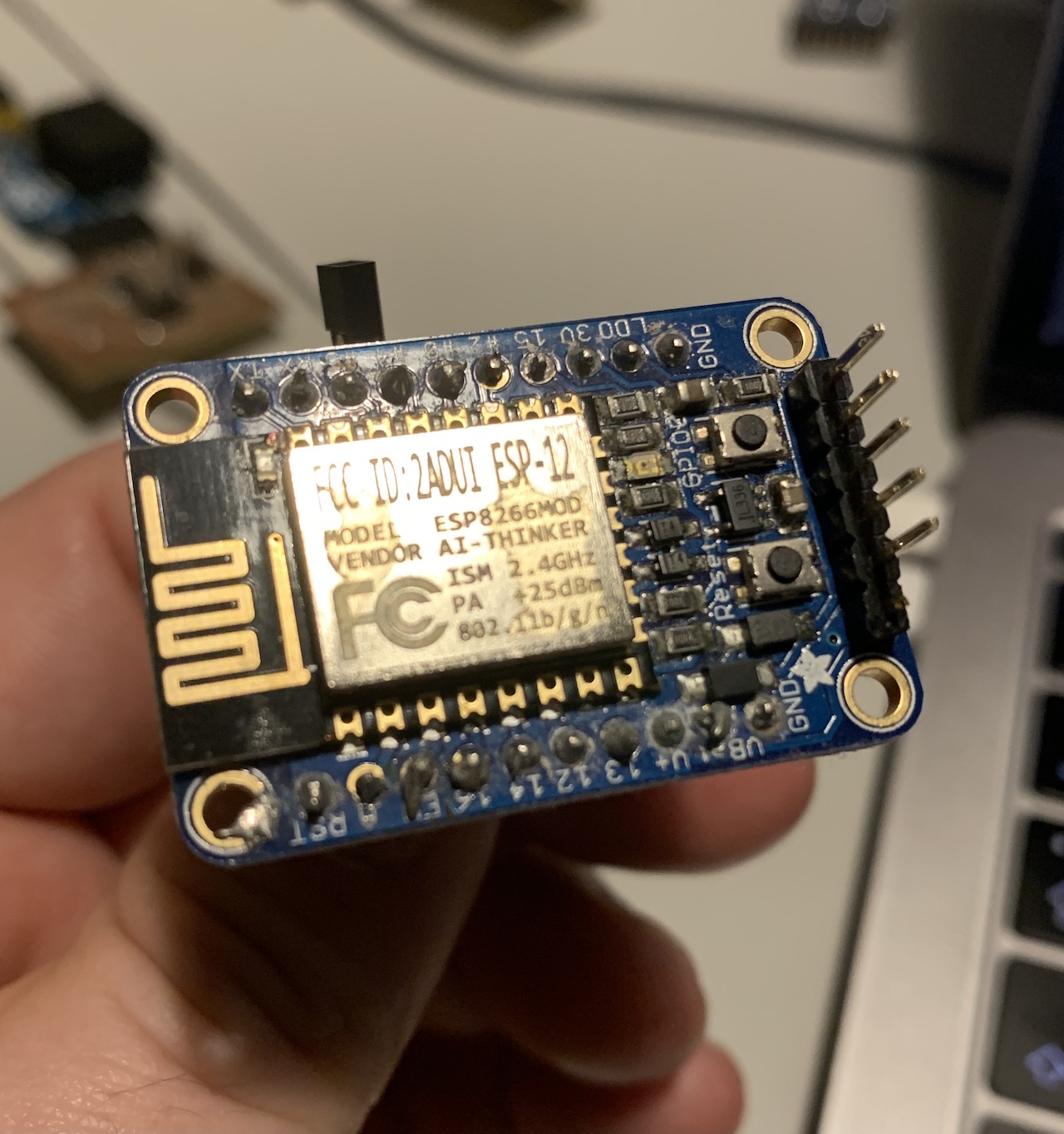
Because i had a ESP8266 around i decided also to try it and have a http server receiving GET requests and trigger flashing of leds in the boards, from anywhere in the wifi network. I plan to use this type of connection on my project, so it’s going to be also a small exploration work to eventually be used in the future.
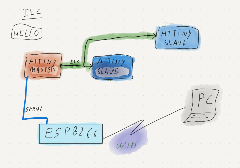
Connection schema drawing
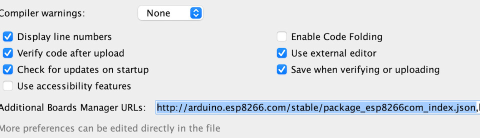
For this i used Arduino IDE. Added the library url
http://arduino.esp8266.com/stable/package_esp8266com_index.json
into Preferences -> “Additional Boards Manager URLs”
Then clicked on Tools -> “Board Manager” to install ESP8266 Boards into Arduino IDE.
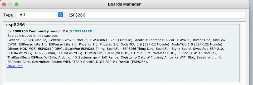
For my test started from the HelloServer.ino example.
So changed the STASSID for my wifi network ssid and STAPSK for respective shared key. Then removed the “HOOK EXAMPLES”, for some reason the code was failing to compile with these and i wouldn’t need them for my teste. Added code so that when the browser accessed (GET) the ESP8266 IPV4 Address on port 80 (http) with url “/pcb/1”, the ESP would write into serial the number of my PCB board to flash the led. Then the ESP8266 sends back http 200 response with message.
server.on("/pcb/1", [](){
  Serial.print('1');
  server.send(200, "text/plain", "trigger led flash on pcb 0x21");
});
server.on("/pcb/2", [](){
  Serial.print('2');
  server.send(200, "text/plain", "trigger led flash on pcb 0x22");
});
After selecting the board in the Arduino IDE and programmed the ESP8266, tested http connection with browser.
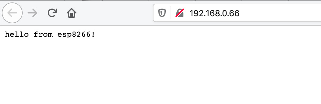
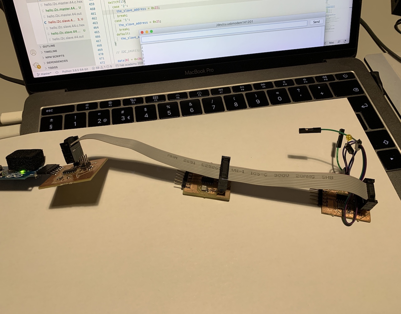
Then i connected the TX/RX of the ESP to the RX/TX of the master PCB and used the browser to make the GET requests to flash the leds. It worked properly! so any computer connected in my wireless network could flash my pcb boards led via ipv4 http connection.
File: esp8266.ino
Links
- https://github.com/esp8266/Arduino
- https://github.com/esp8266/Arduino#installing-with-boards-manager