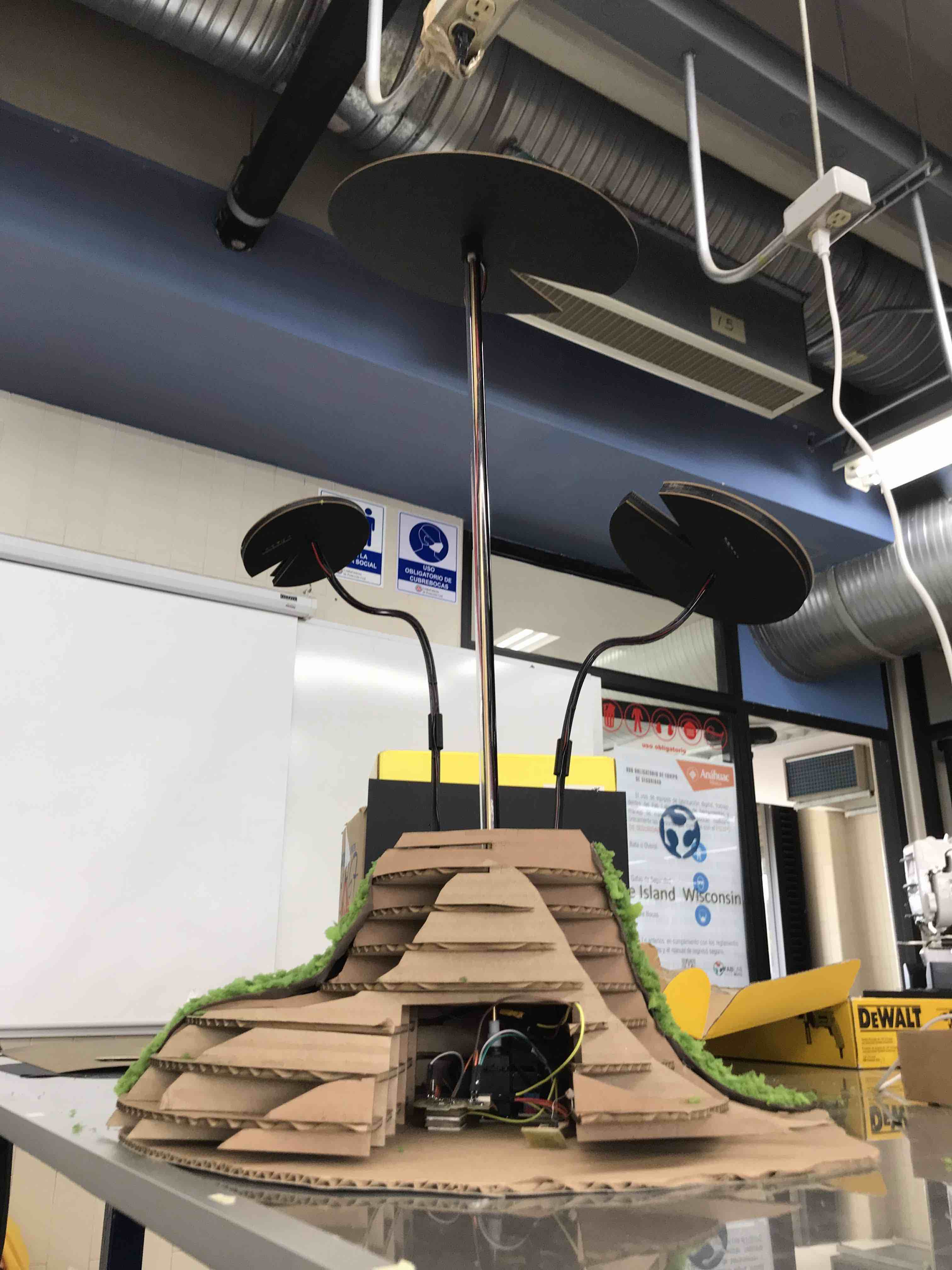
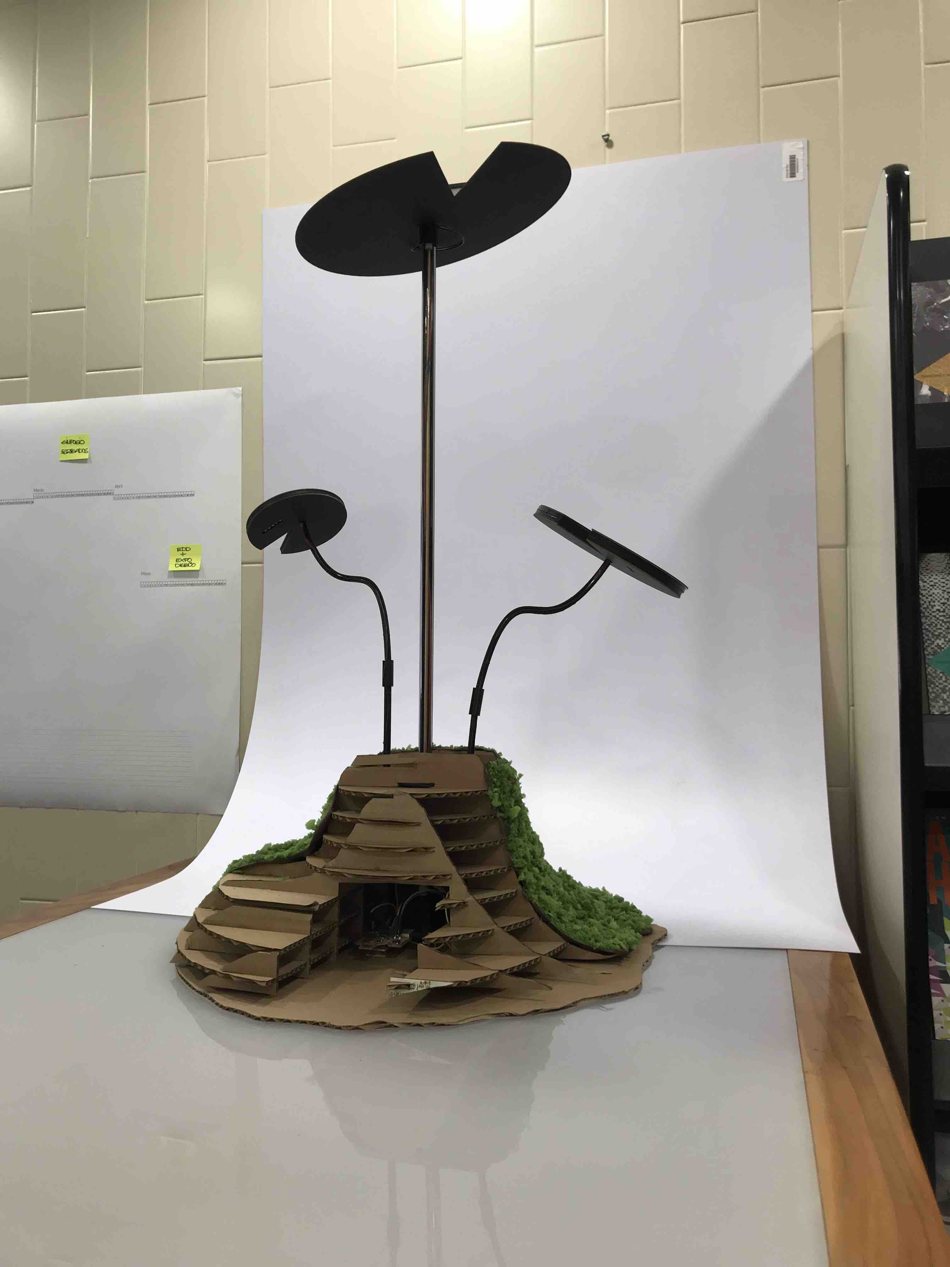
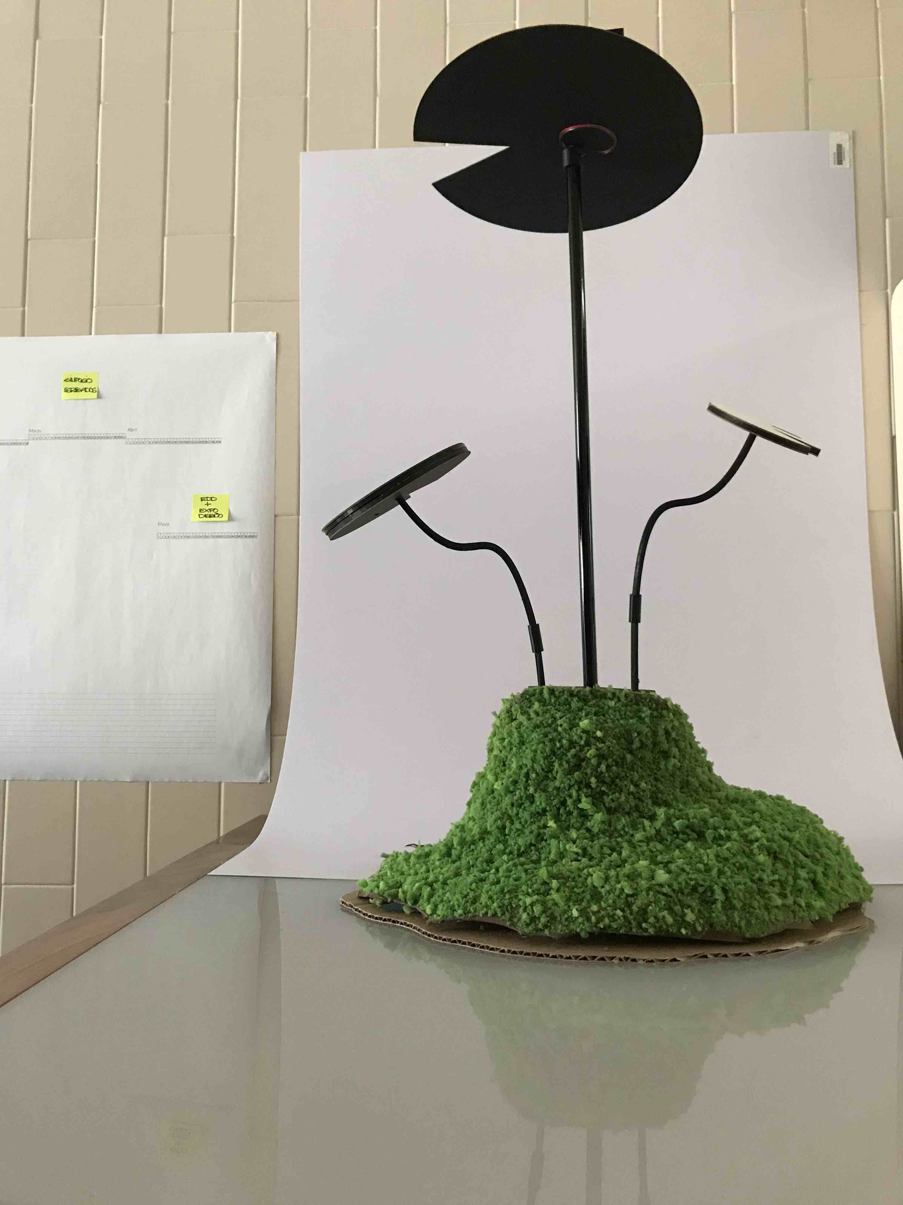
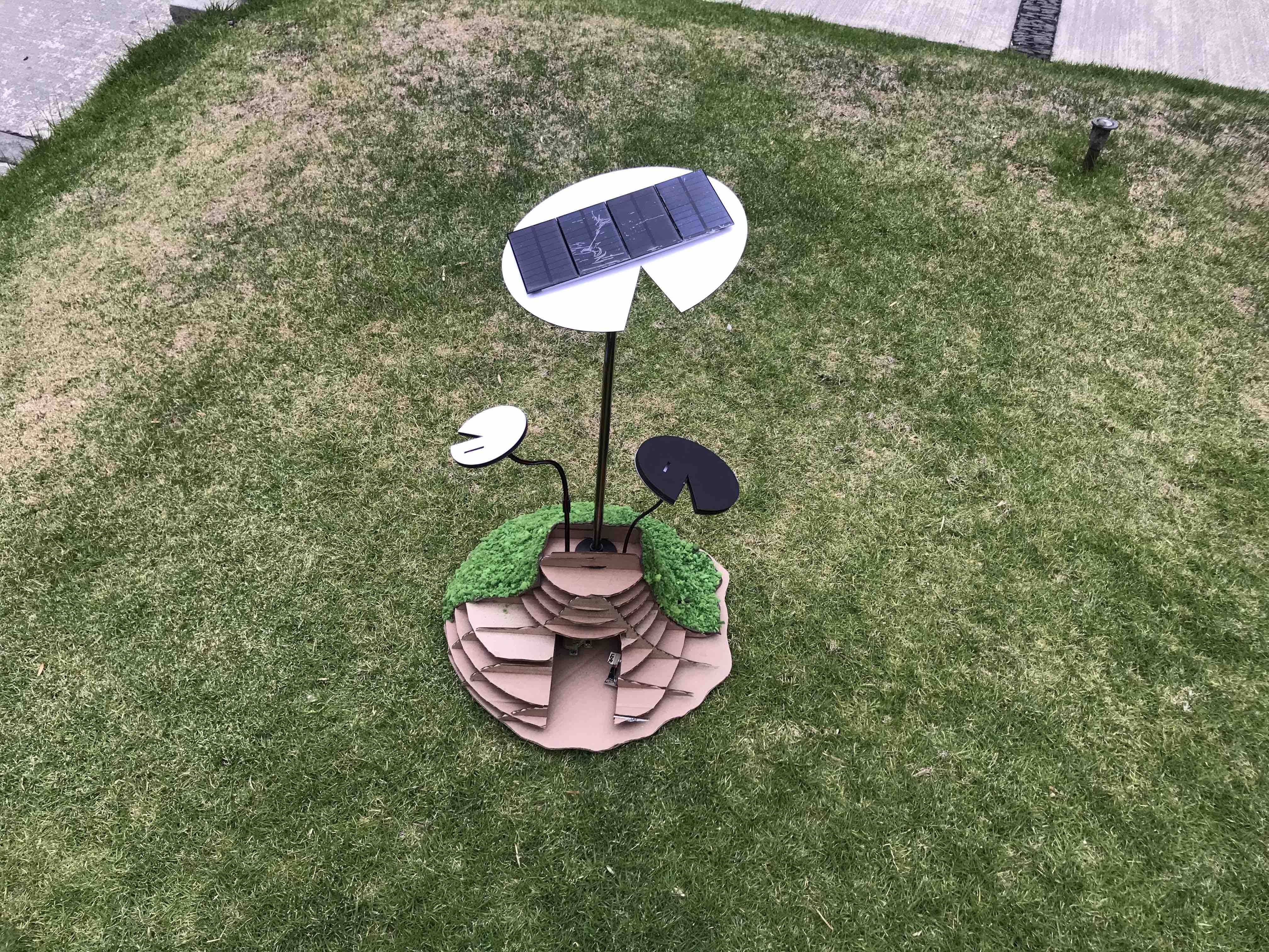
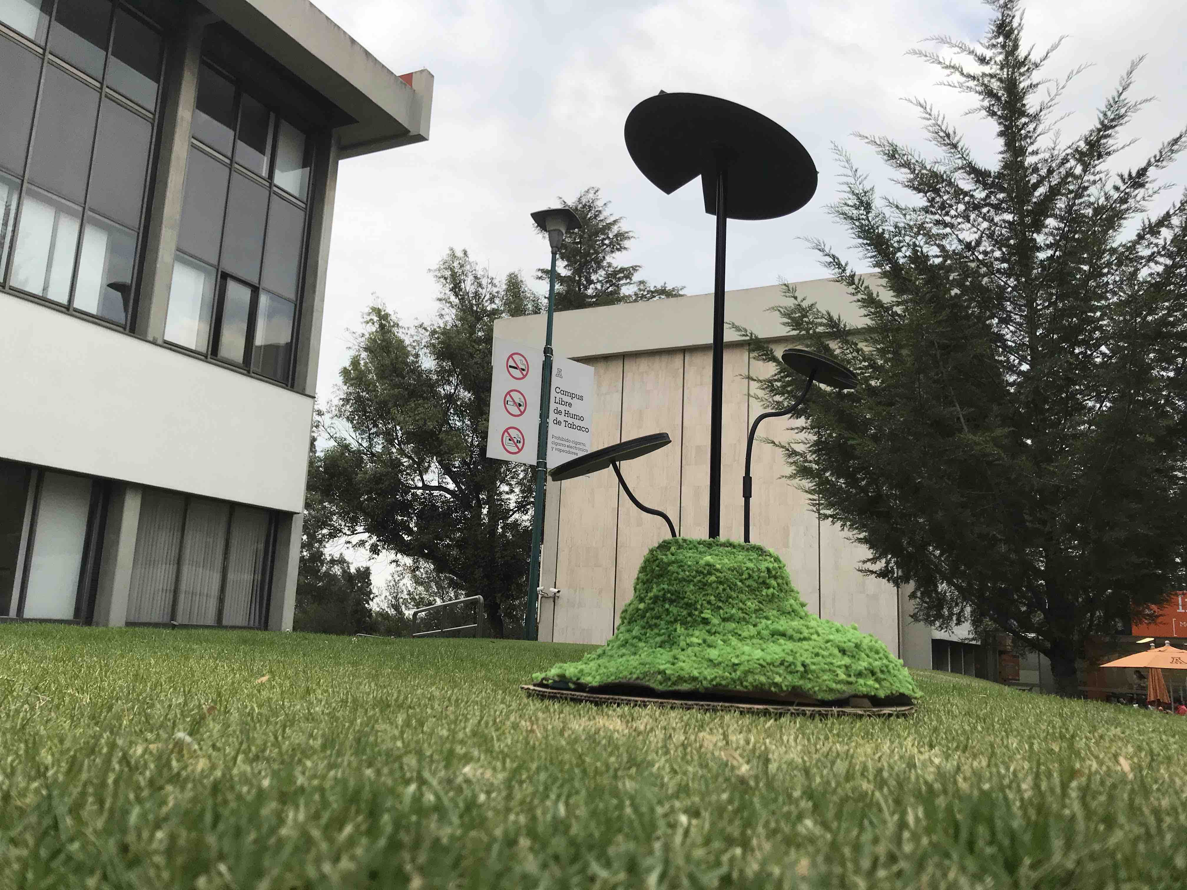
Hero shot.
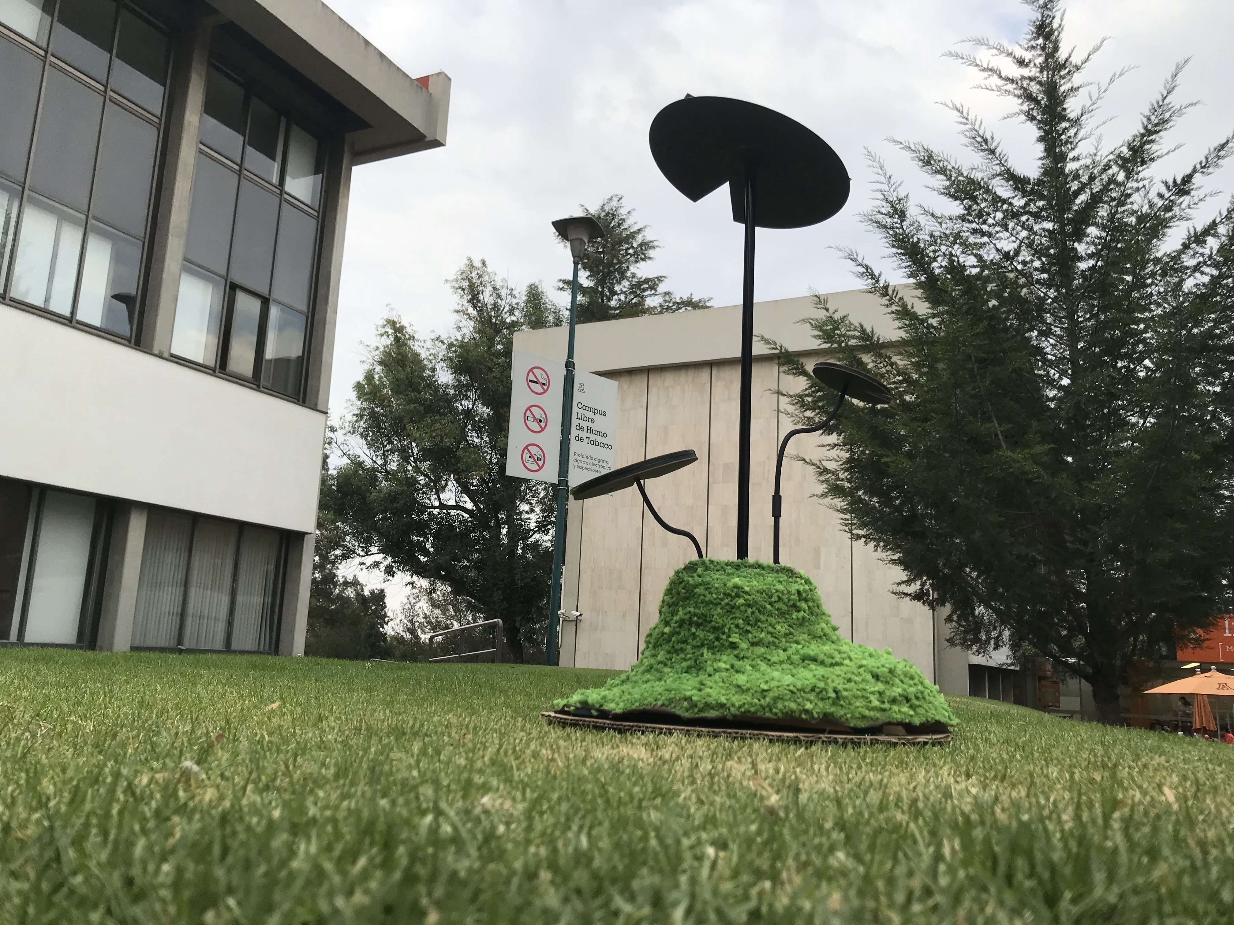
First, the Social
Responsibility committee launch de "Green Campus" iniciative and I
decide that I want to present a project to the authorities. The
inspiration for my project begun when i saw a public luminary
outside the University Campus that had Solar Panels, then I just
remember that our students love to rest over the grass of the
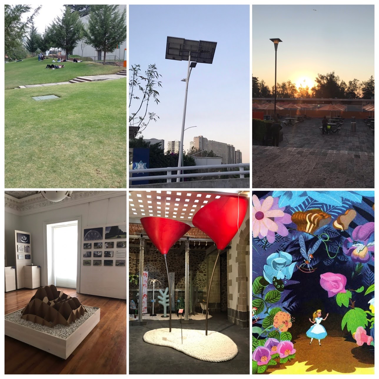
Campus, then I remember one exhibition that held in Mexico City a
few years ago that I helped to mount in the Museo Mexicano de
Diseño that the Trienalle di Milano brought, and some of the
objects exhibit there resemble this big flowers like in Alice in
Wonderland and for last I remember a project that one former
student design like 2 years ago in my class, the objective was to
use Biomimesis to design some decorative or functional object and
she, Paulina Russ design this Lirium like little lamp to use it in
a bed side table and then I think this project could look awsome
in a bigger scale, really bigger scale like some 6 or 7 meters
tall. This proyect is about giving our students a place to rest,
to study, to talk, to re-connect with nature, with each other, to
have a conversation without devices, an old-fashion conversation
an "analog" one, so I talk to Paulina about this project and she
agree to participate with her original design.
So, I start to design
the new form , function and the electronics to accomplish the
requeriments that was to build a mockup to show it to the
authorities in the frame of this "green campus" iniciative in
collaboration with Paulina that help me to design the lower base
of this new big Lirium.
DESIGN of the green spot
a place to re-connect
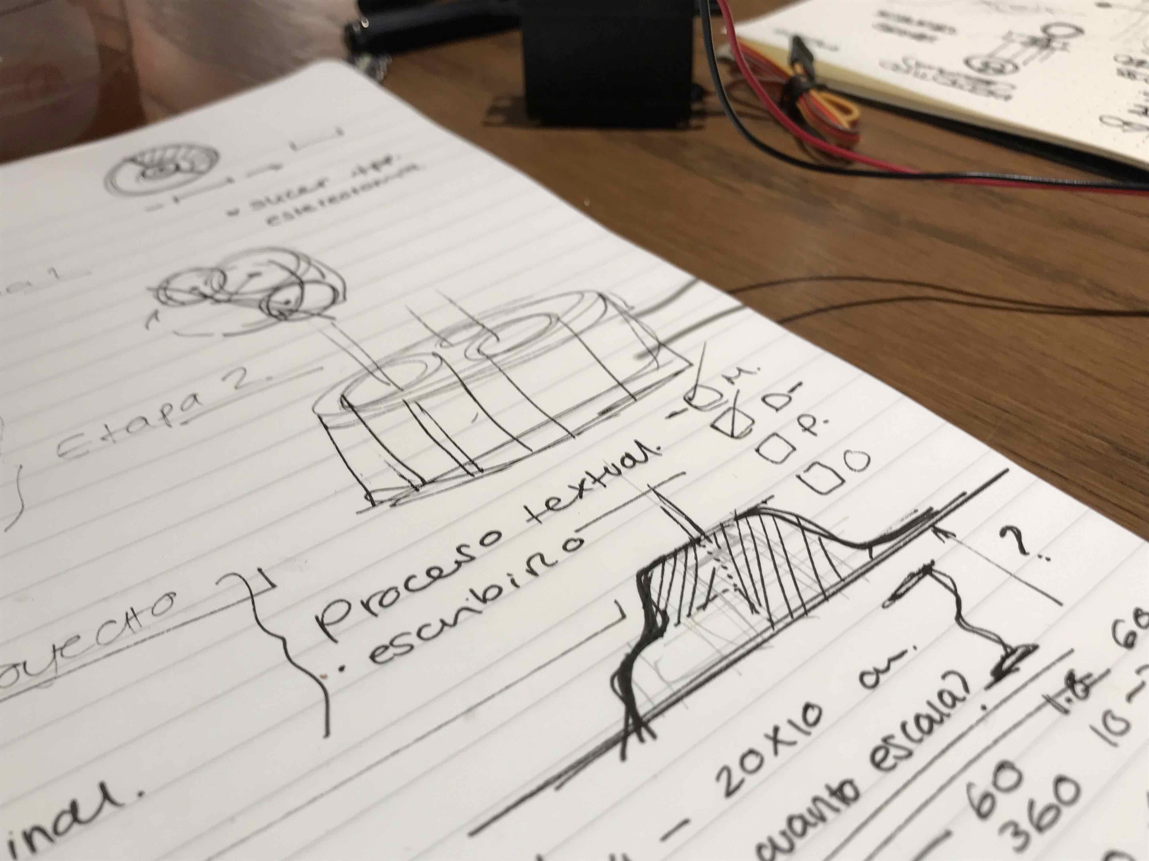
Here are some
sketches and notes regarding the redesign and activities to do.
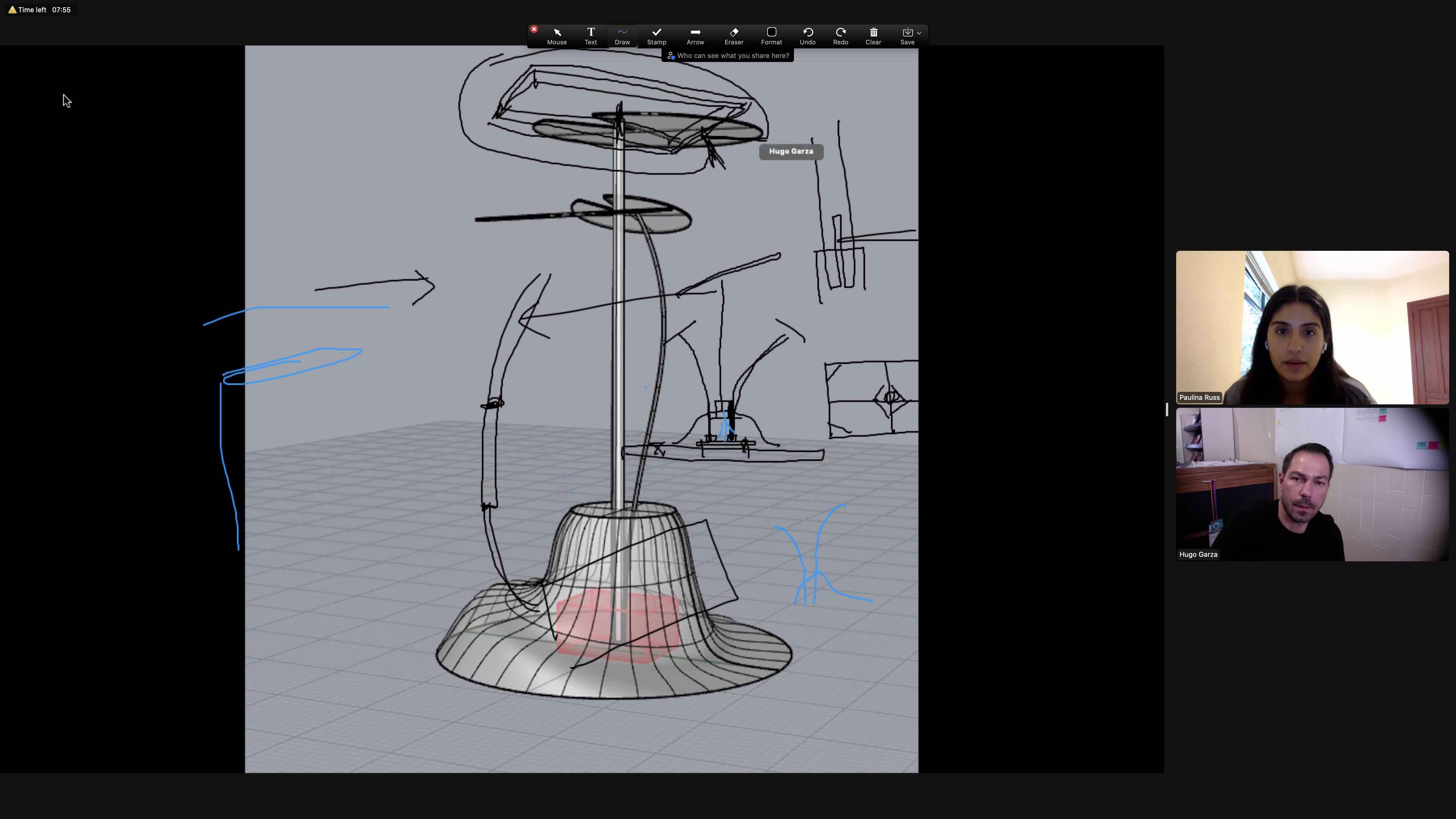
She is Paulina. Here we
are sketching the new components of the green spot over a 3d image
so she can redesign the base and I can continue with the design of
the new components.
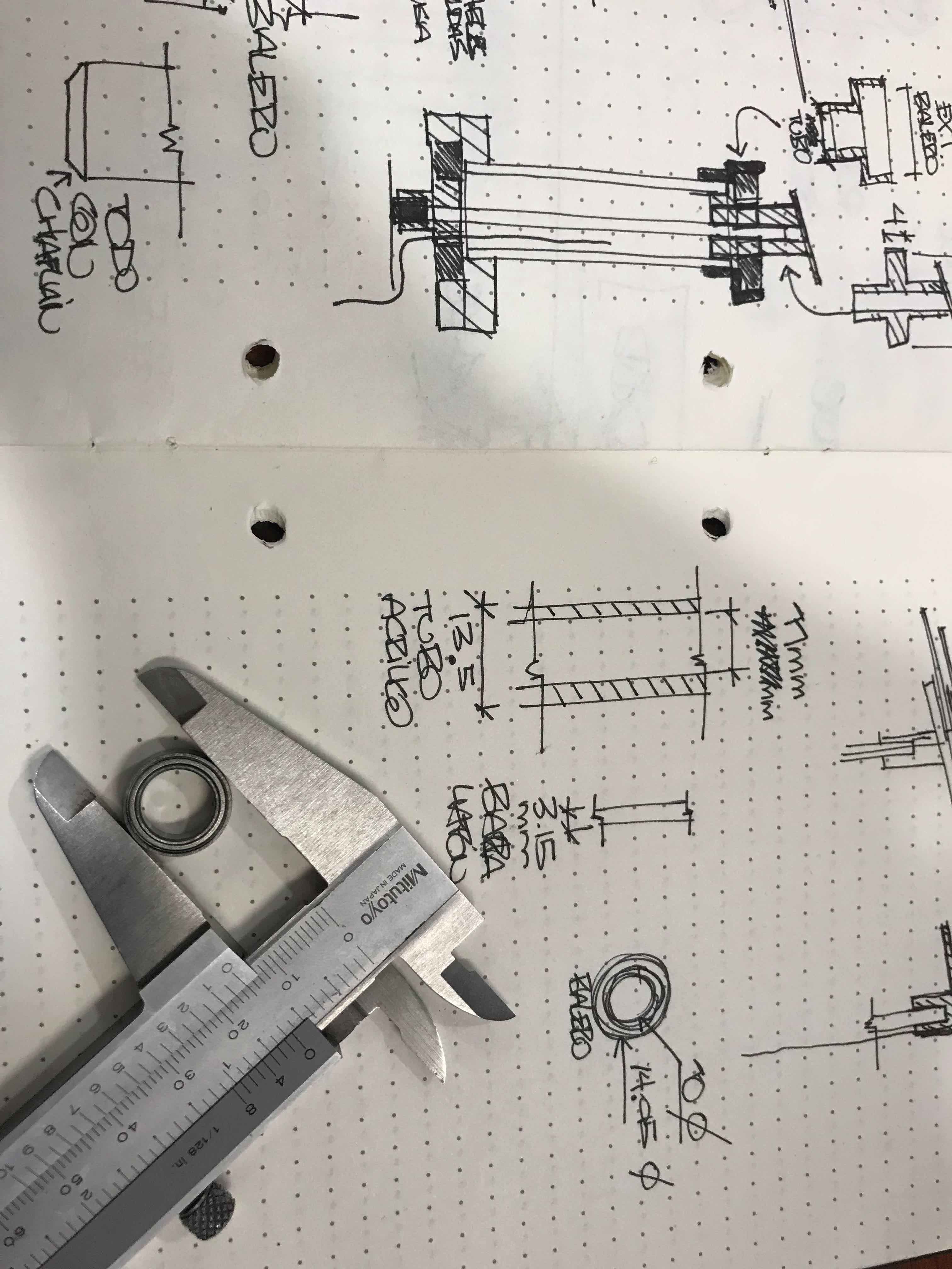
Measuring the
bearings so I can start filling the Parametrycs in fusion360
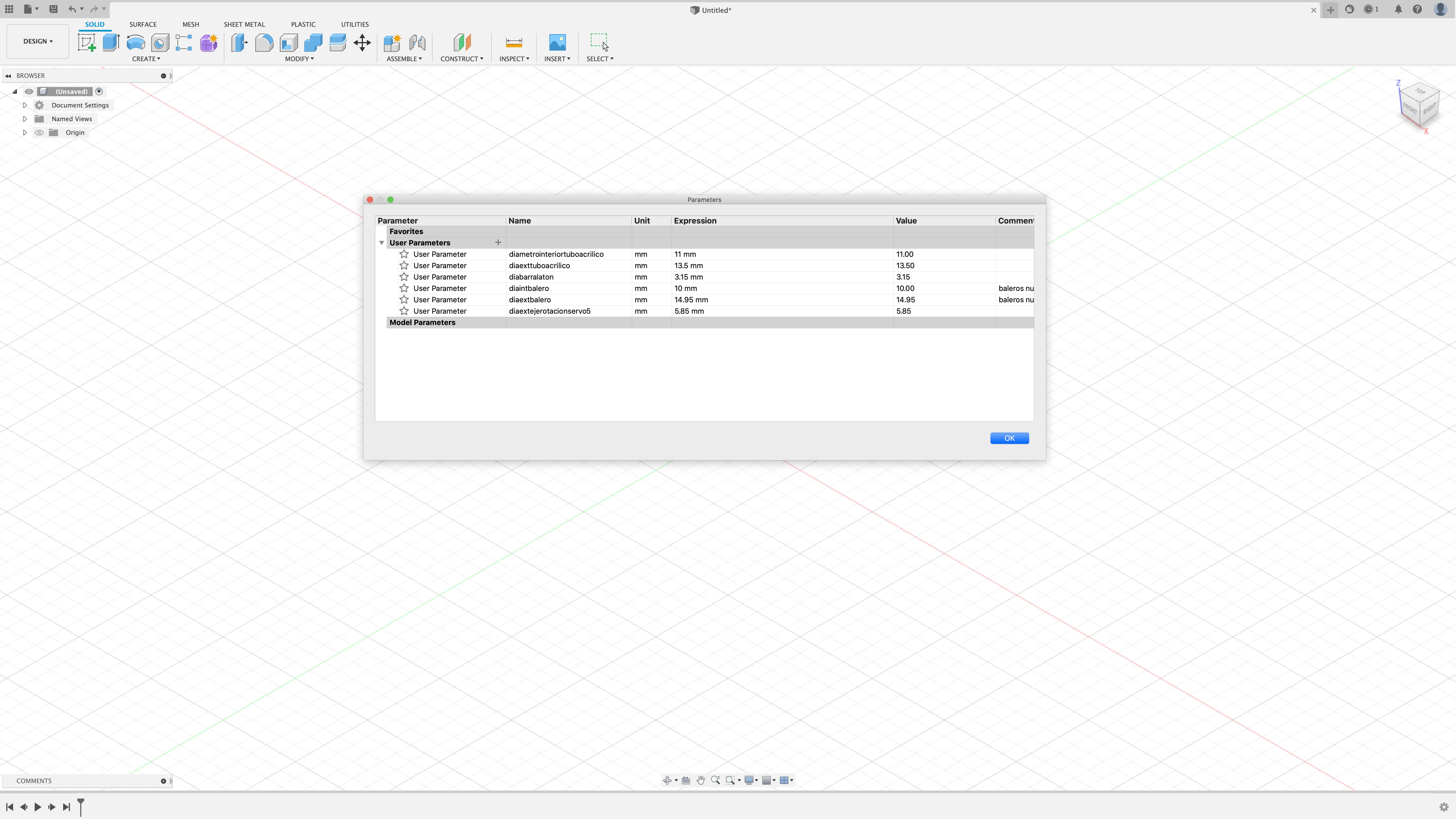
This is the
Parameters window, her you can add or change your own data, like
NAME (name your parameter) UNIT (mm, cm inch,etc) EXPRESSION (the
dimension like 11, 12 or 34) VALUE (is the same that you use
in EXPRESSION).
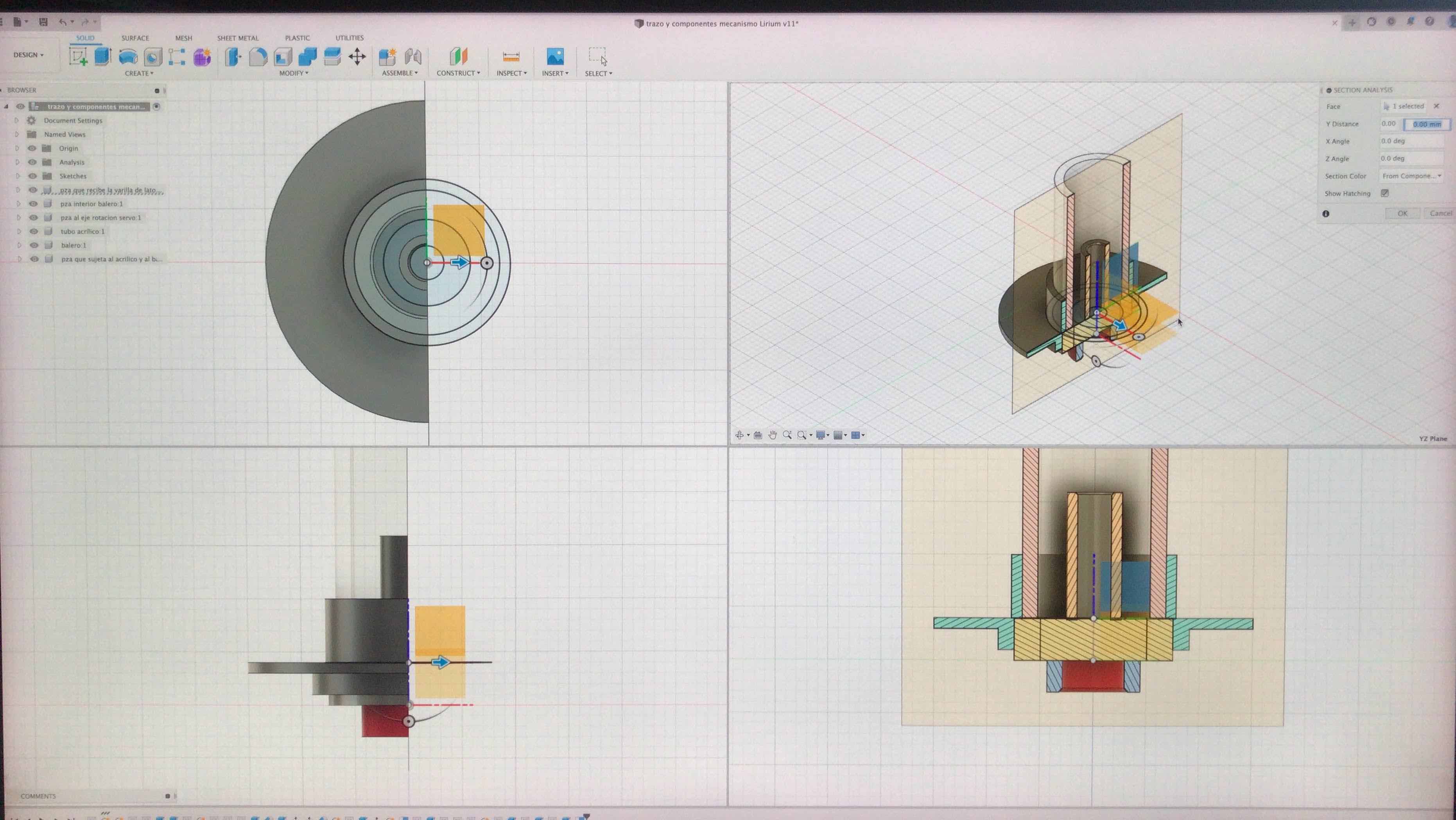
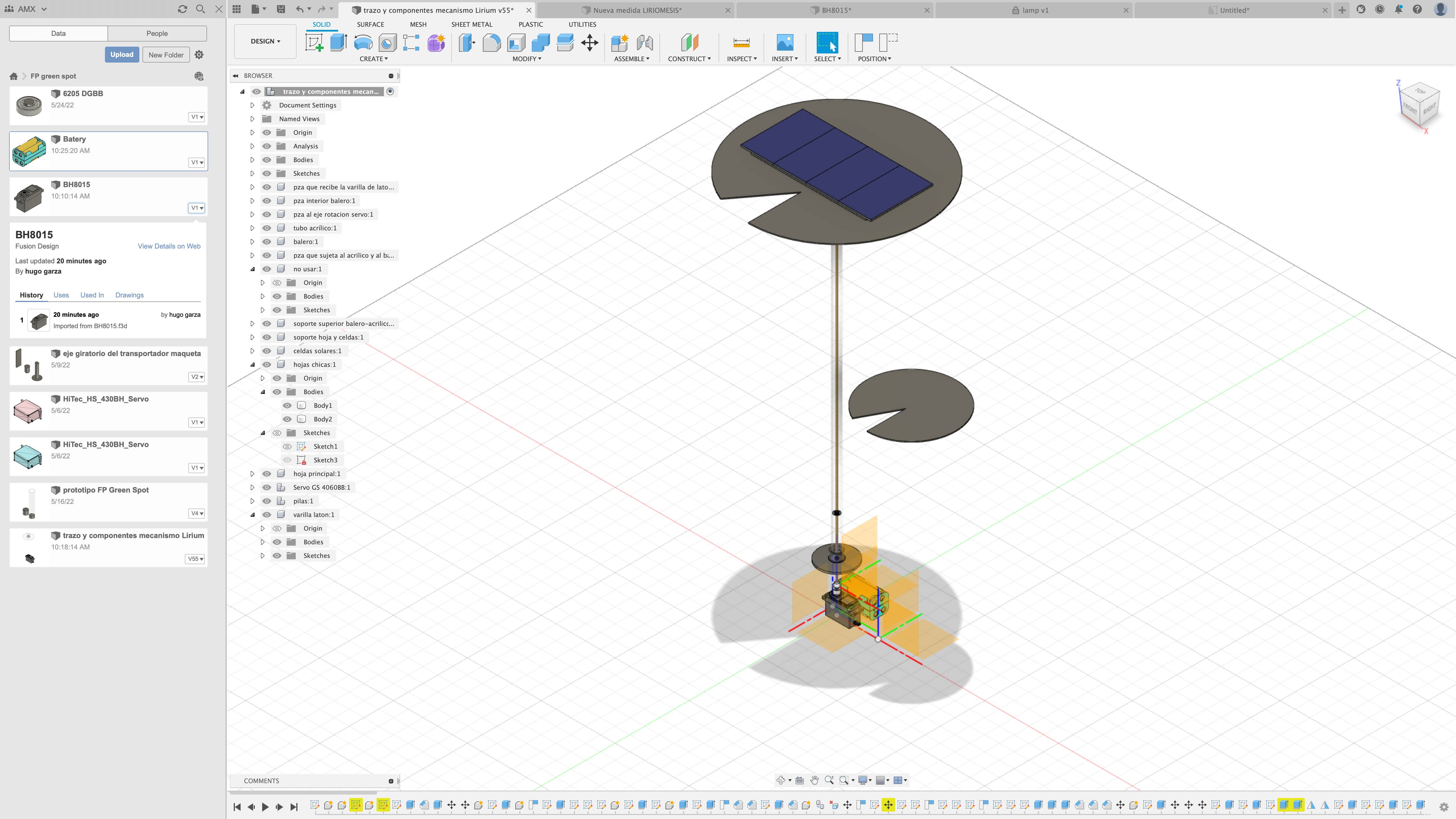
A section view of
the bottom support of the rotation axis, with the bearing, the
brass rod and the acrylic pipe. To design this I use the
parameters mentioned above, if I need to change a component, or
put some tolerances I don´t have to redraw nothing, just change
the EXPRESSION value of the parameters I already use.
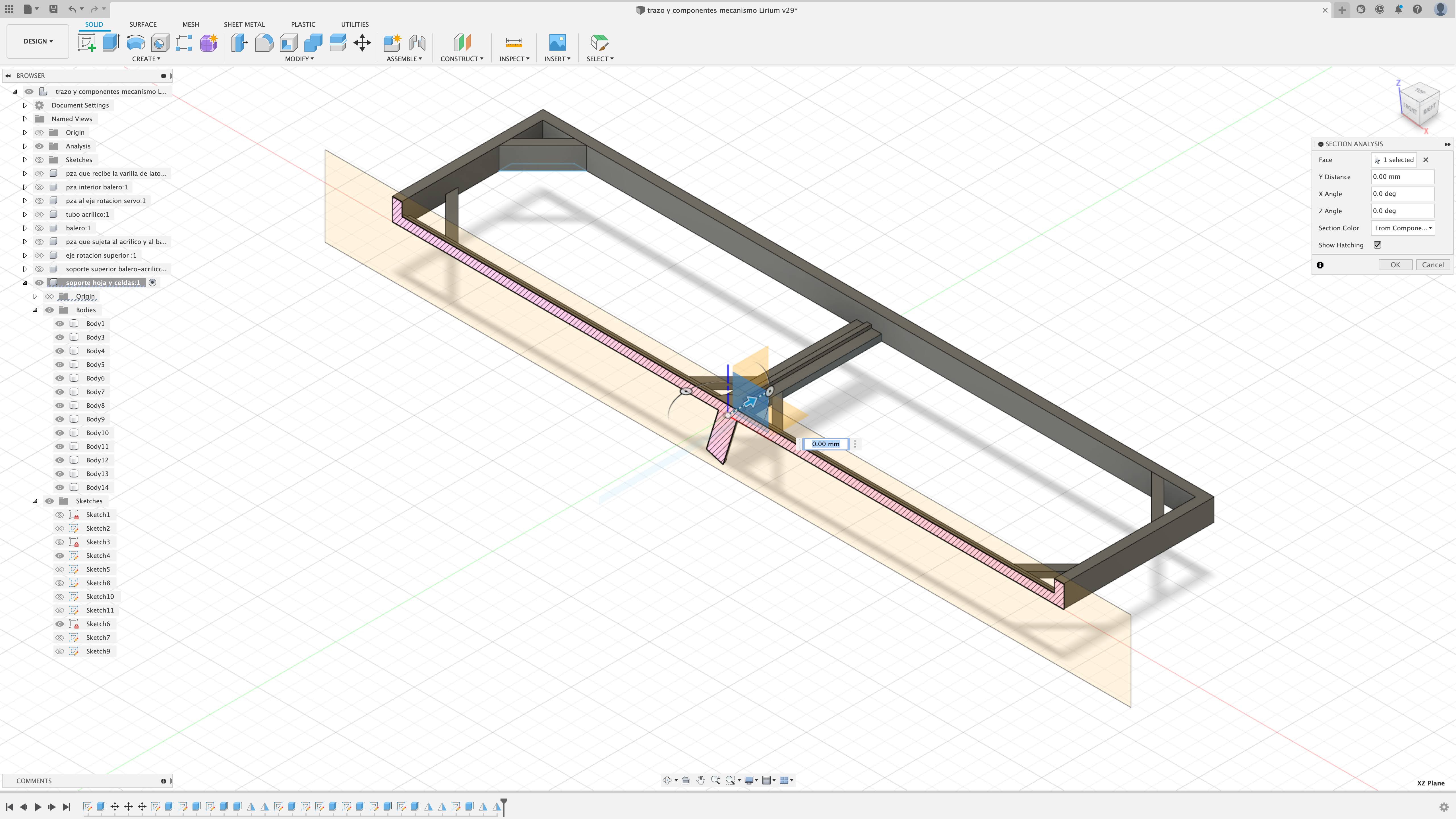
A section view of
the solar cell support that will be 3D printed.
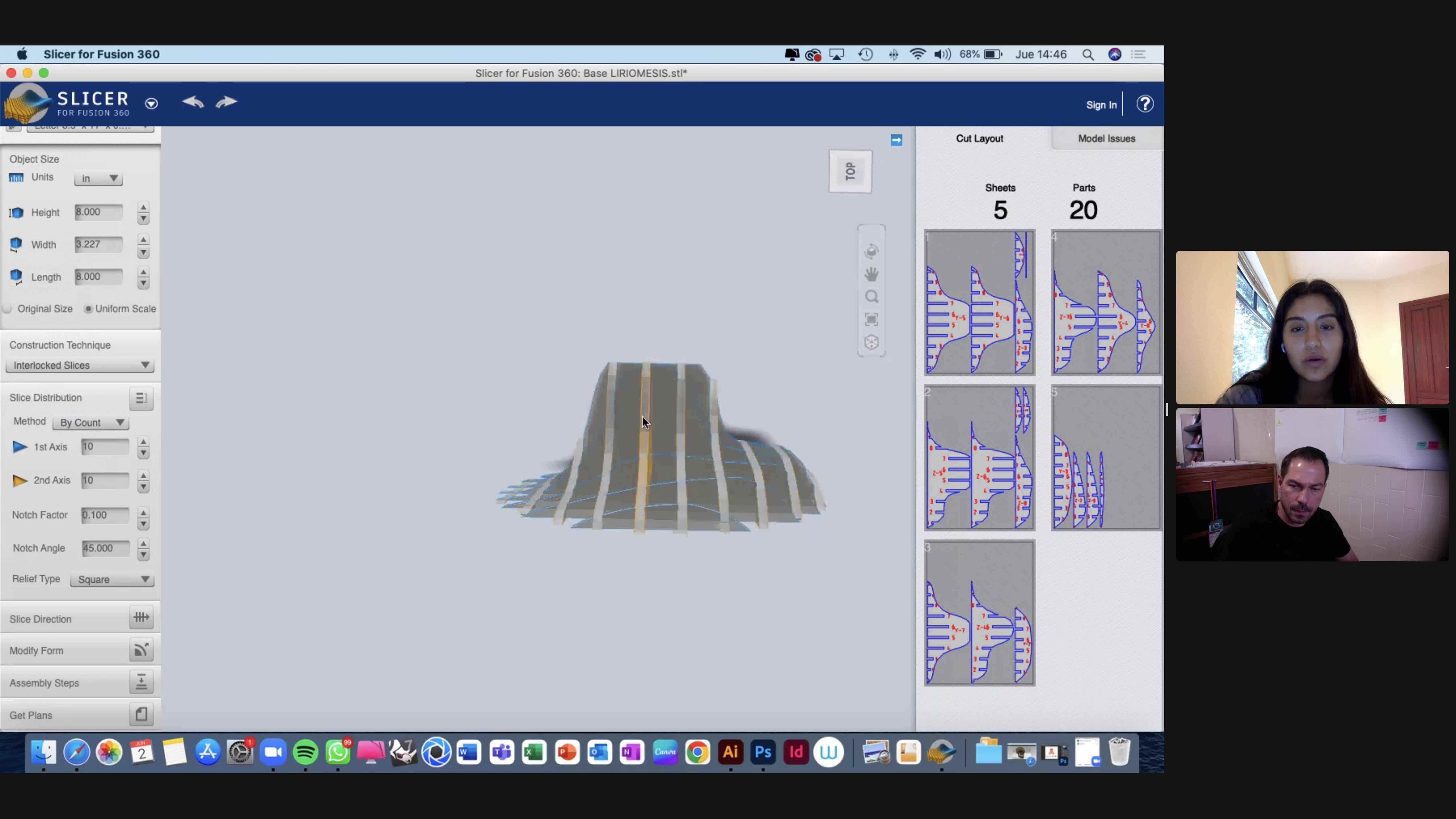
Cheking the base
3D model in Slicer, this software convert your 3D models into
different forms of construction techniques, in this case we
use the Interlocked Slices because I want to make it with
corrugated cardboard.
I want to fit
this components into the base, so here I made some drawings
in the image to show it to Paulina so I can explain better
my idea and wich components to fit in.
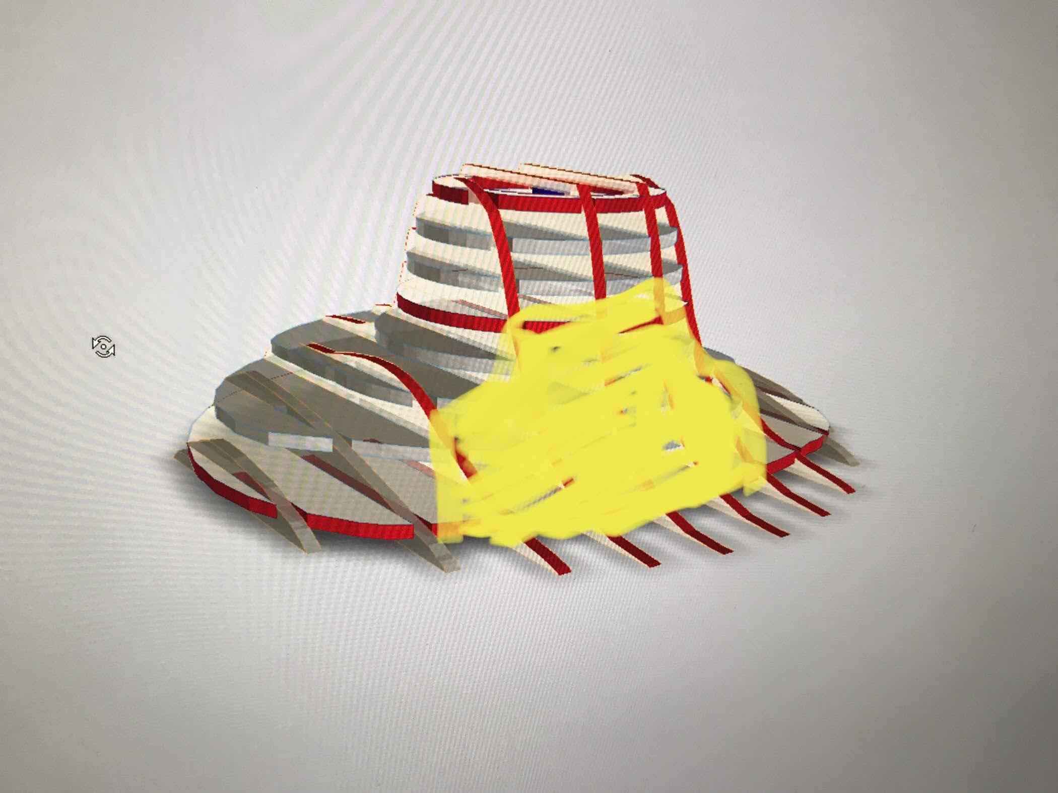
A drawing
direct into the slicer image to indicate where I need the
space to fit those components.
investigation
a place to re-connect
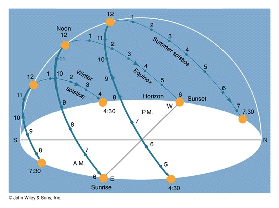
position of the
sun
Path of the sun
here in the Universidad Anáhuac México
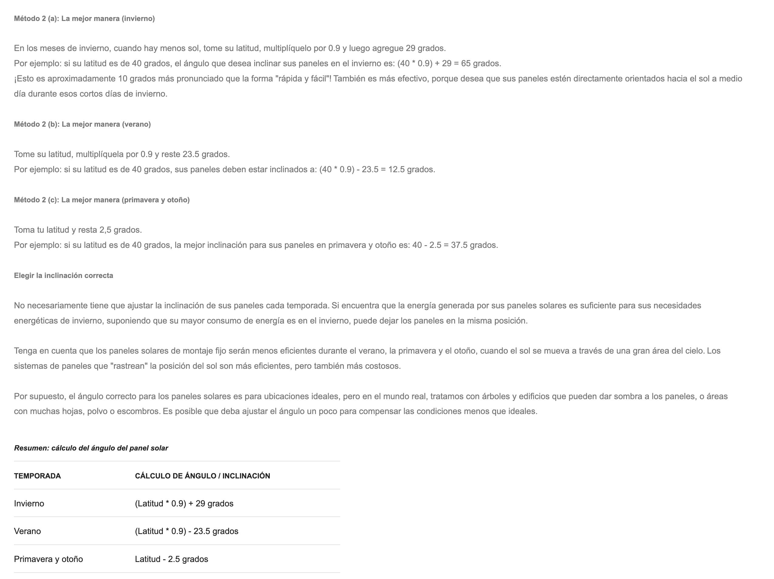
Different methods
to choose the right angle to set up your solar panels
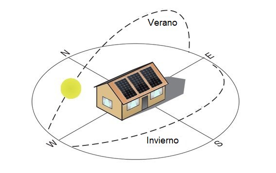
path of the sun
in summer and during winter

the incline I
choose for my panels is 16.9º
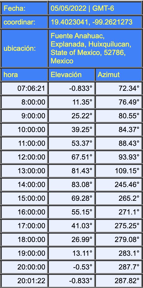
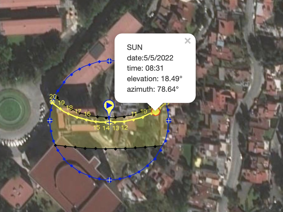
this is a table
with the altitude and azimuth of the sun in its path right
above the University
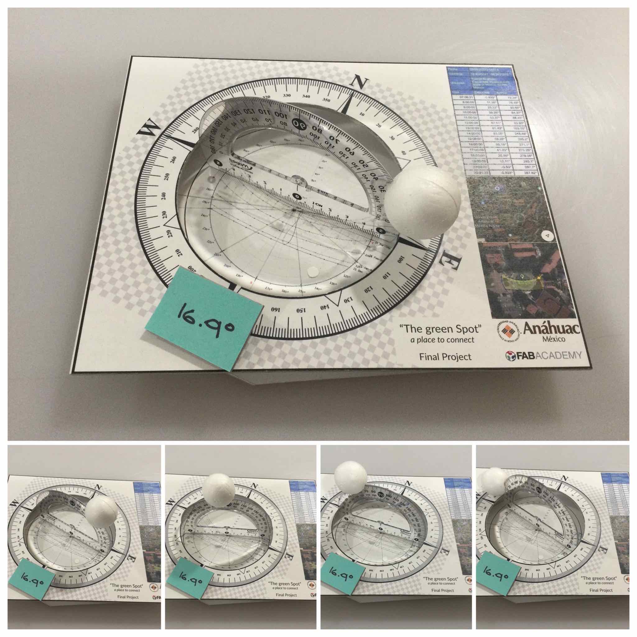
I made this to
visualize the path of the sun mention in the above table, with
this I be able to define the position of the solar cells and
time spending in that position during the day, the next day,
at 6:30 AM they return to the initial position
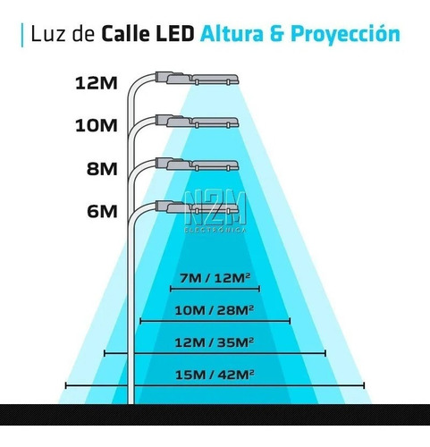
IHere we can see
the recomended high of the leds and angle of light of public
luminairies
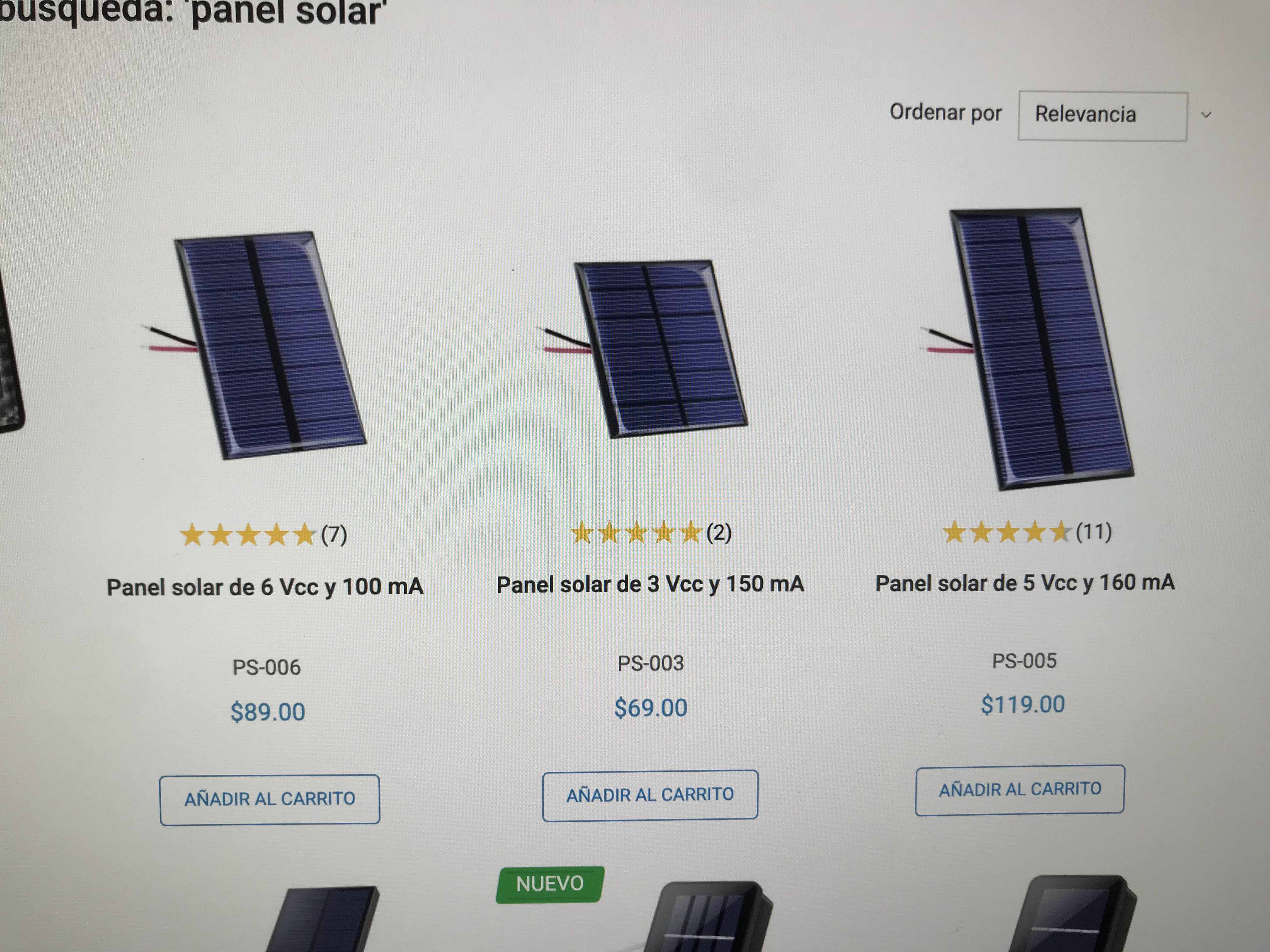
I choose the 5vcc
and 160mA for the project, because of the batteies and the
servo
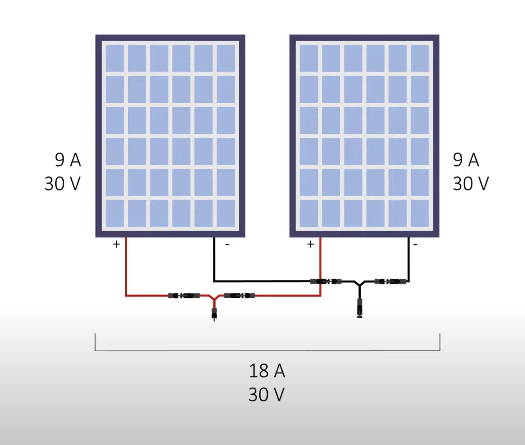
The connection of
the solar panels should be in paralel to maintain the Voltage
of 5V but sum de Amp, in this case 160x4=640mA
production
a place to re-connect
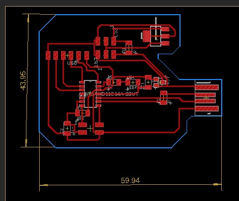
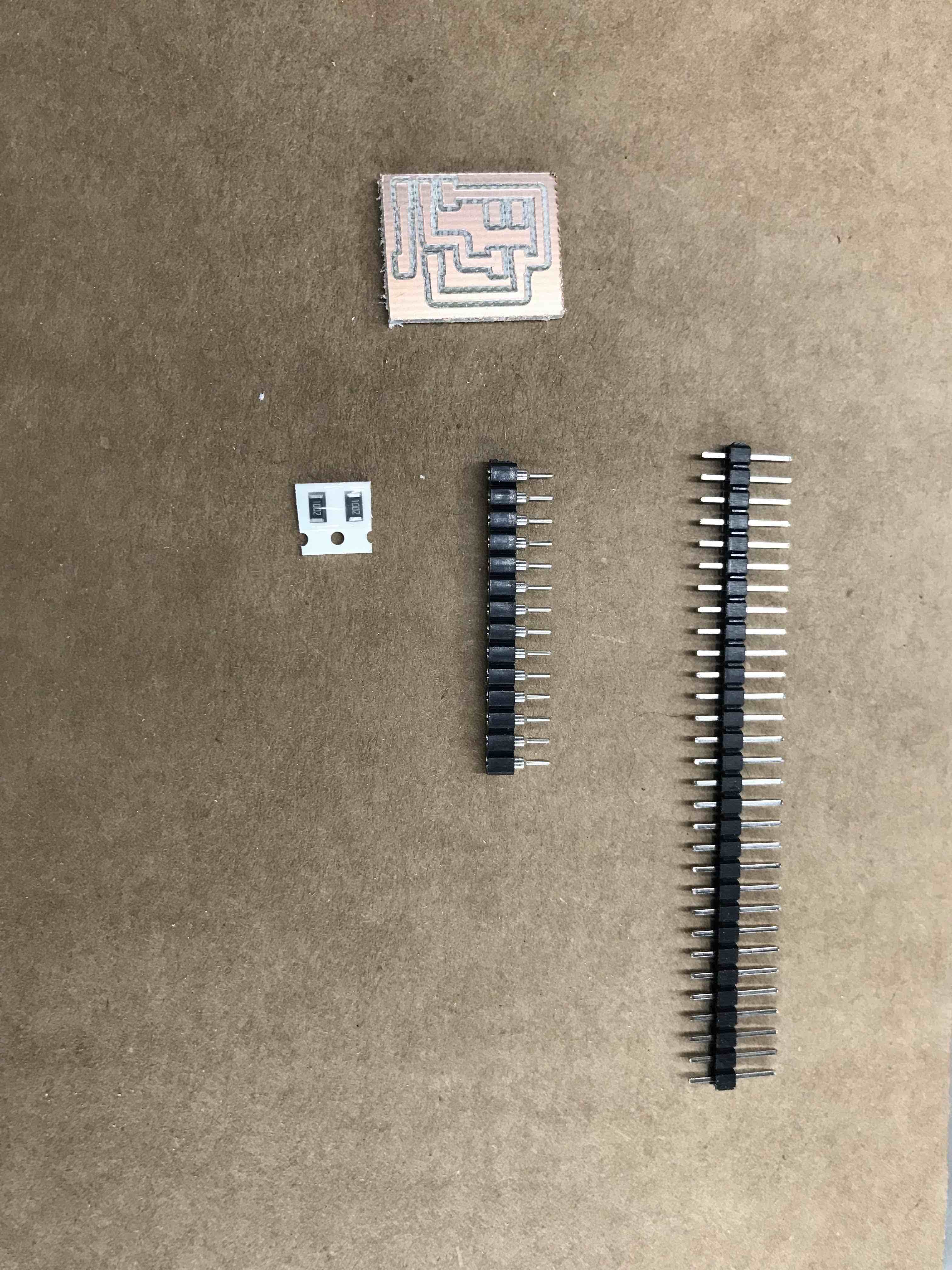
Image of the PCB
with components and traces ready to export it to a PNG image
My redesign of the
SAMDINO, the Hugodino, this PCB its the one who´s going to
control my project
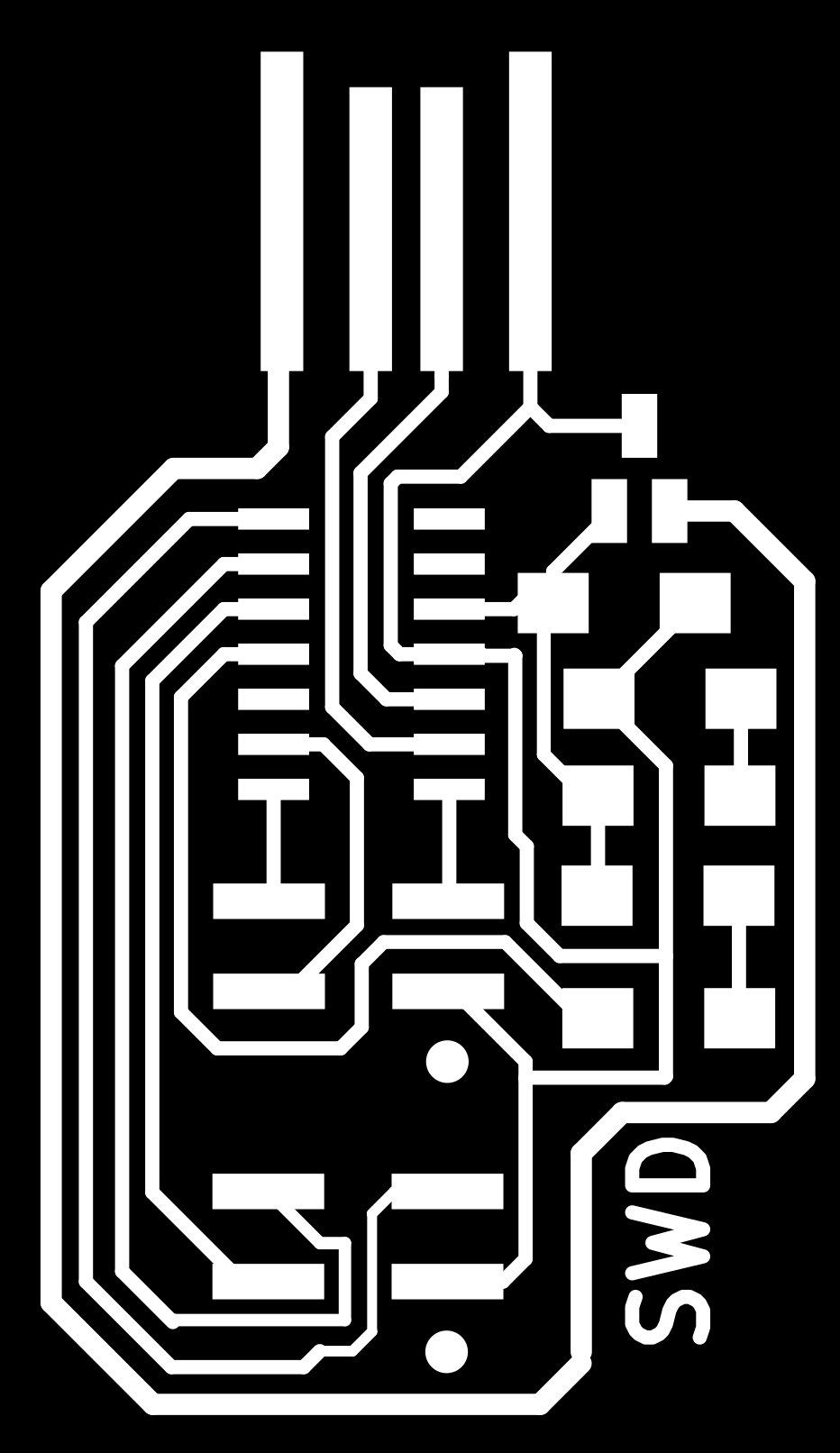
PNG image of my SWD
PCB
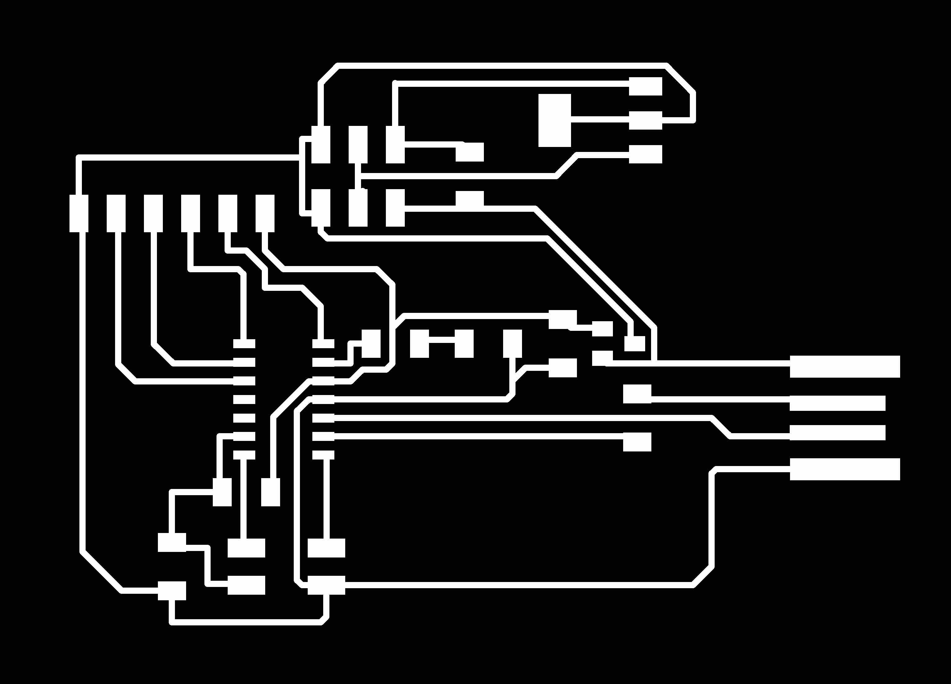
PNG image of my LDR
PCB
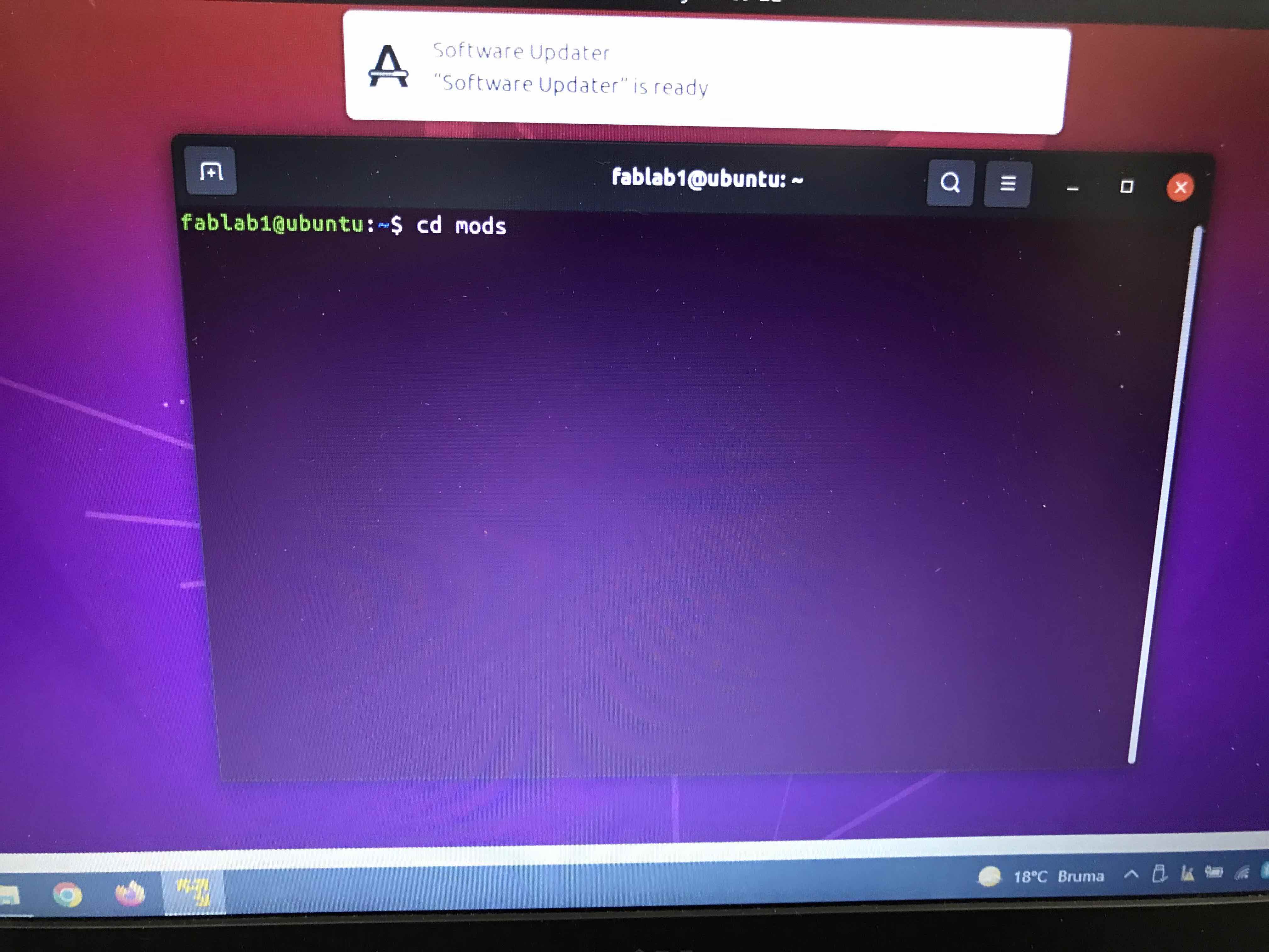
Opening UBUNTU to
open MODS
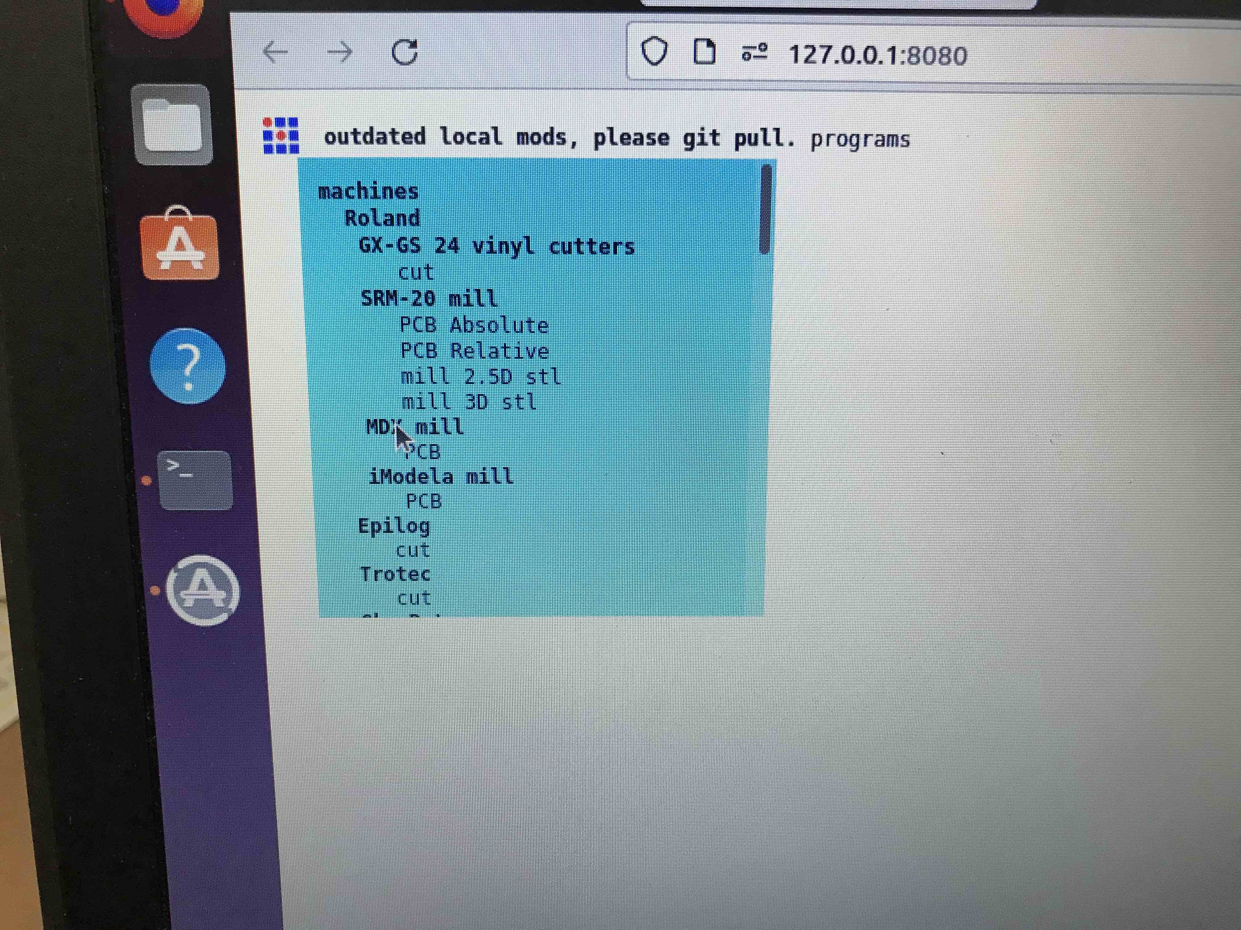
Opening MODS
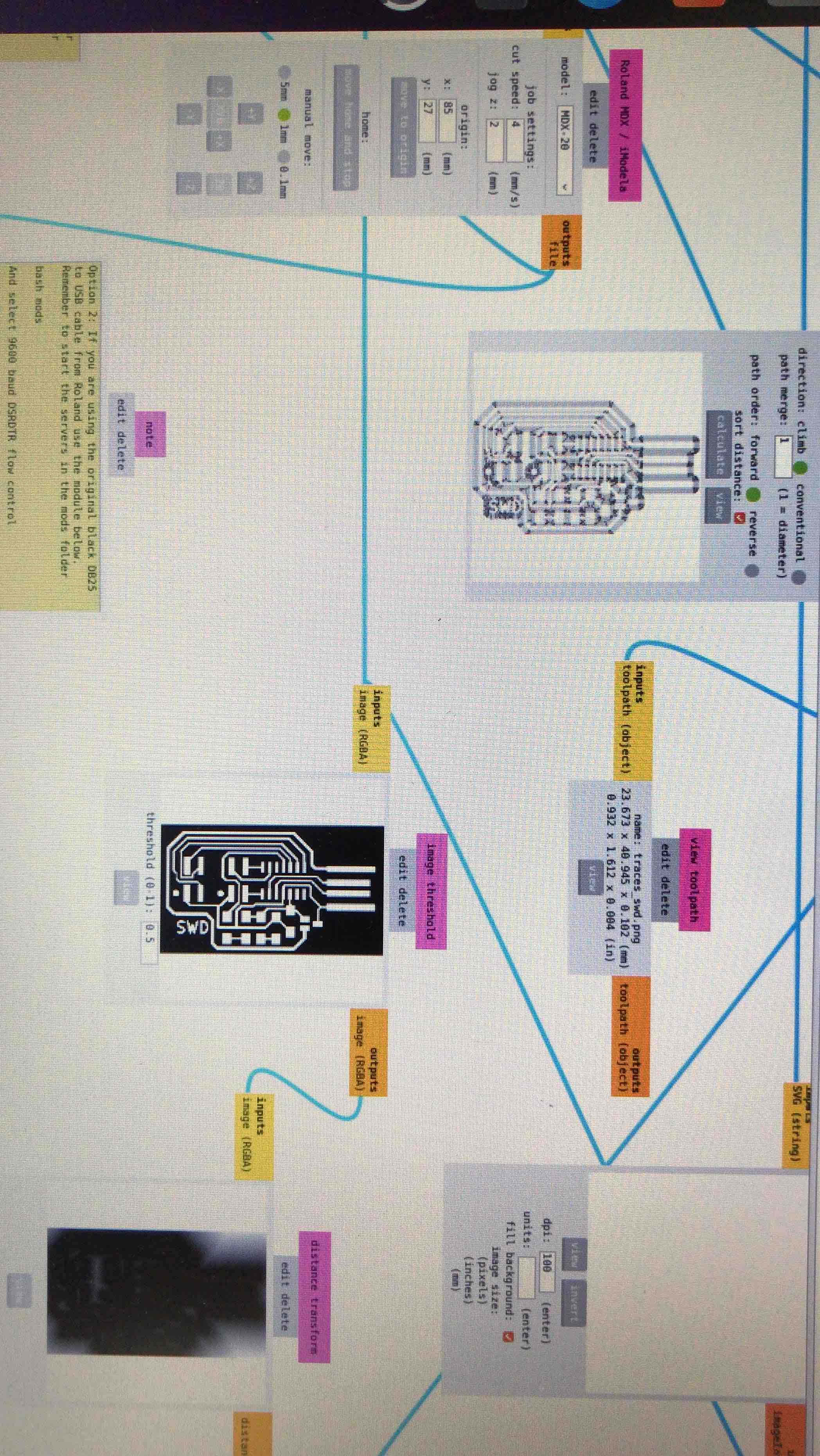
The PNG image of my
PCB, always import a PNG image of the PCB and of the outline if
need it
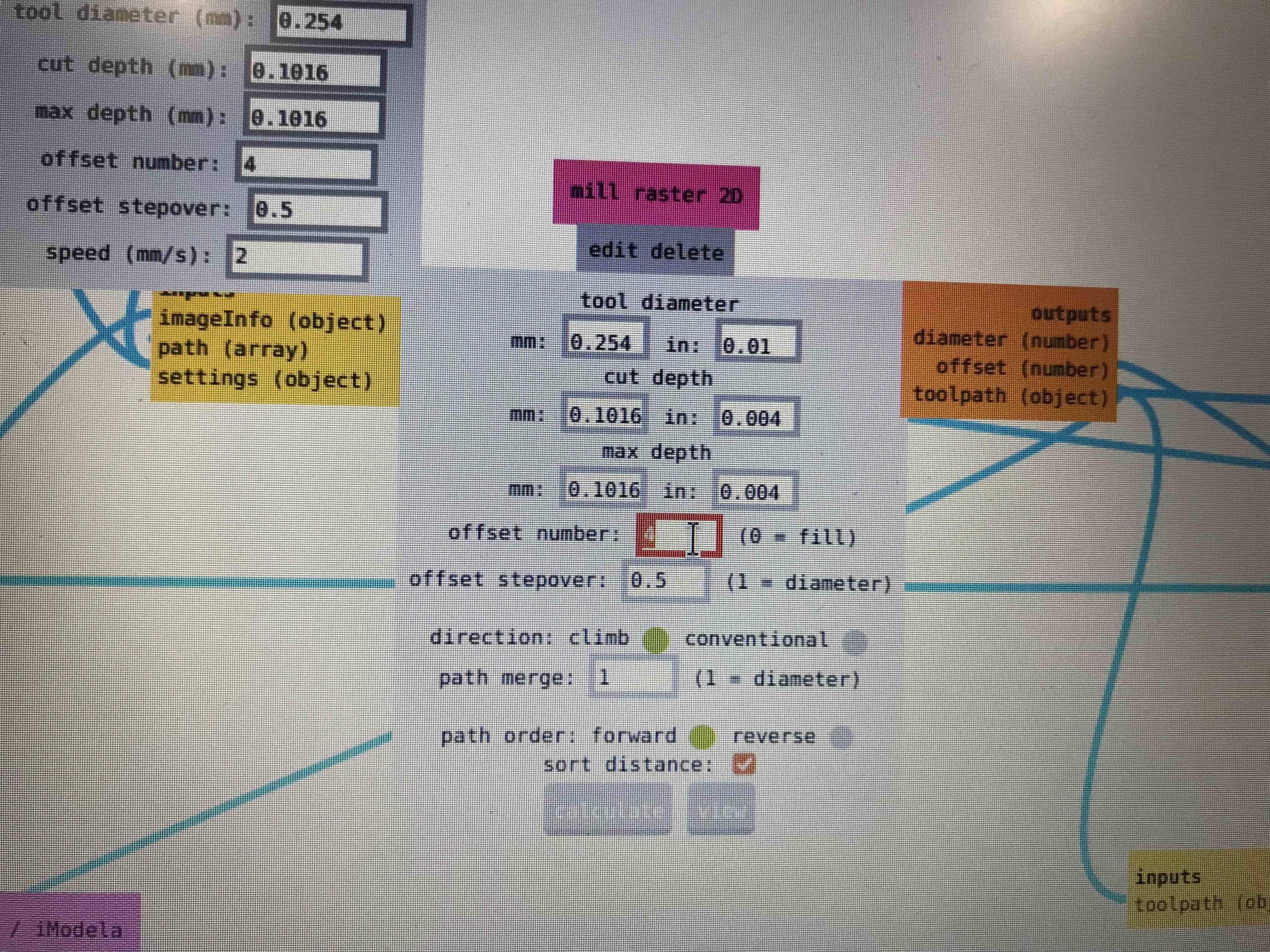
Here I´m about to
change the offset so I obtain better clearance between traces
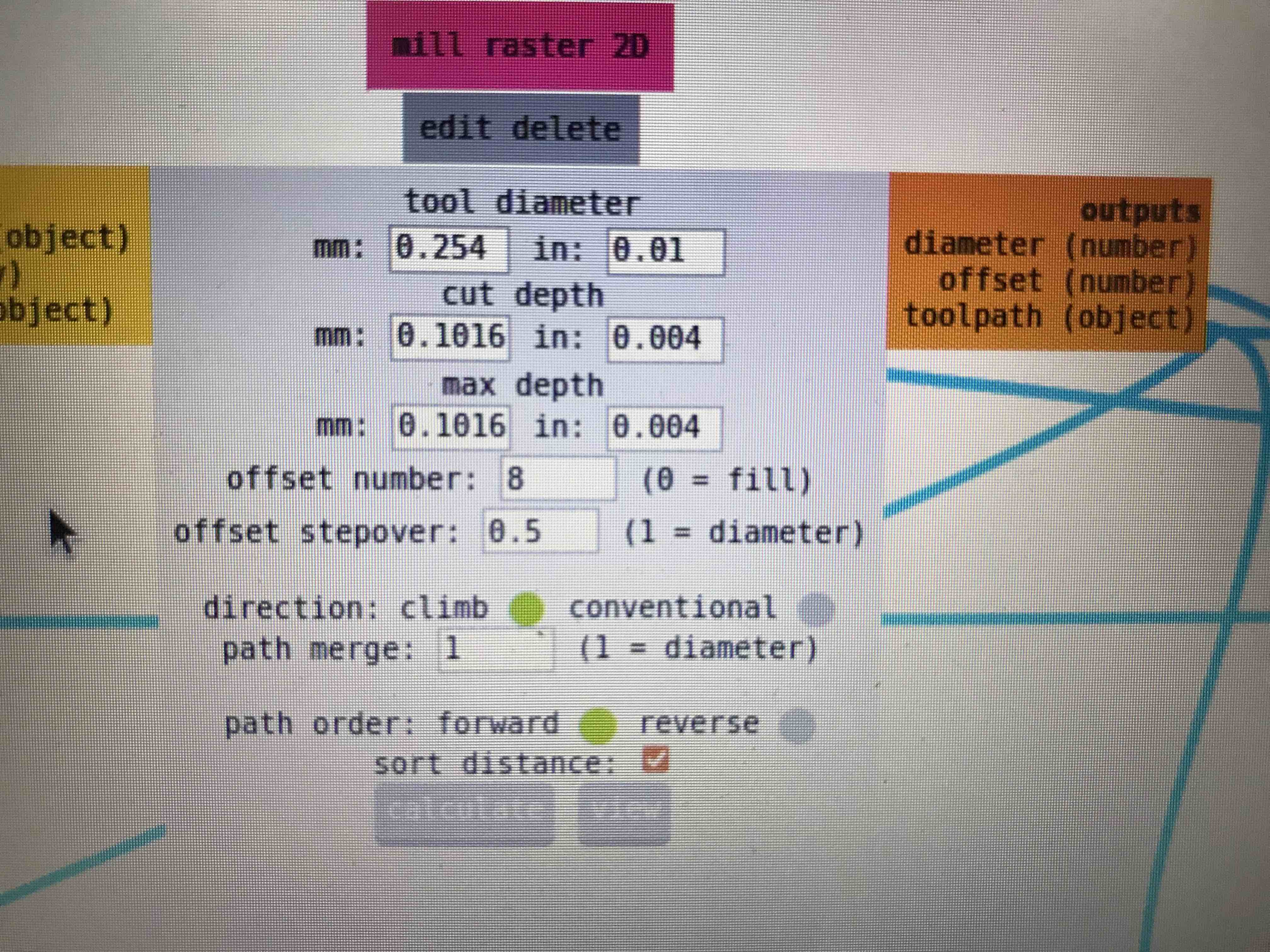
Setting the offset
on 8
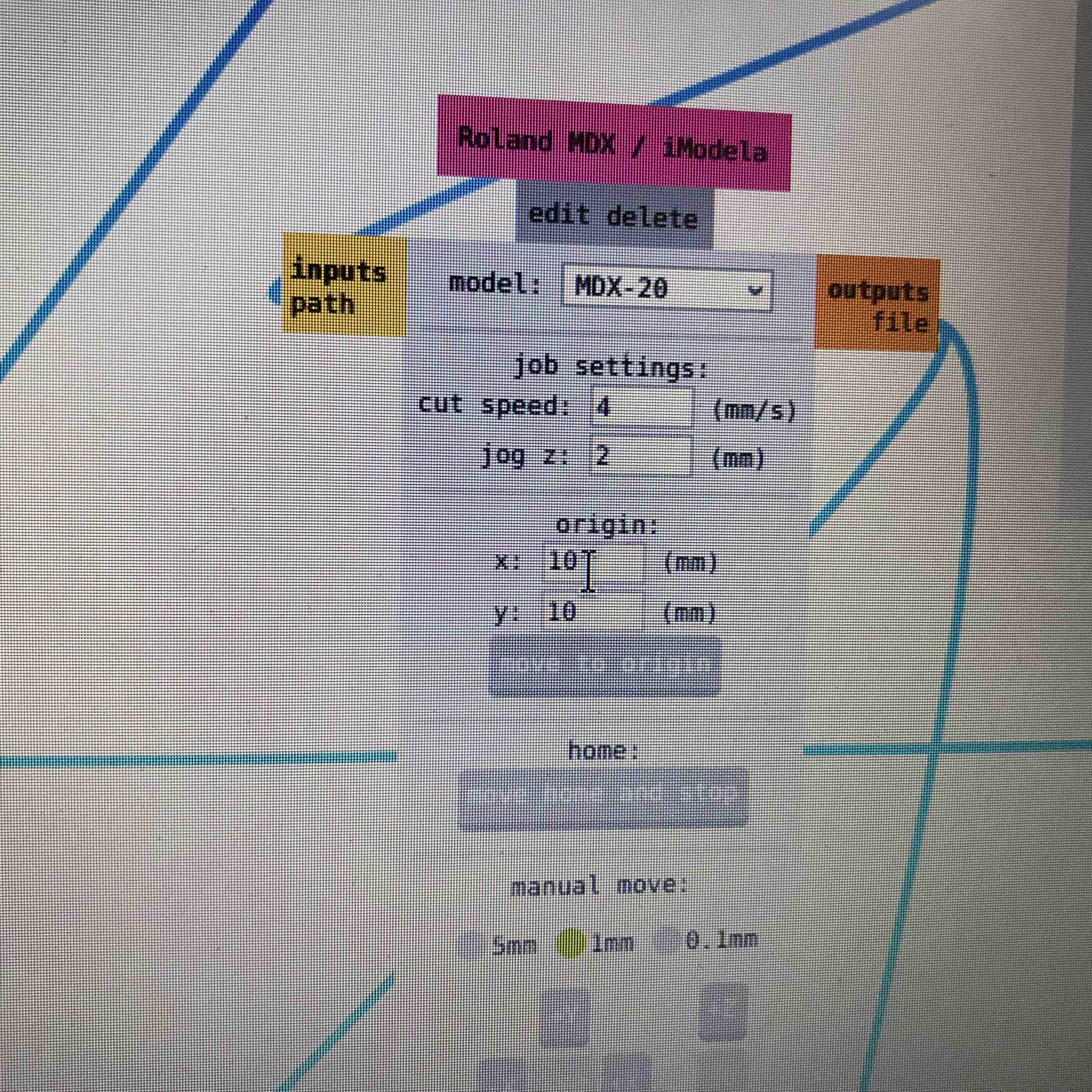
Setting the origin
to start milling
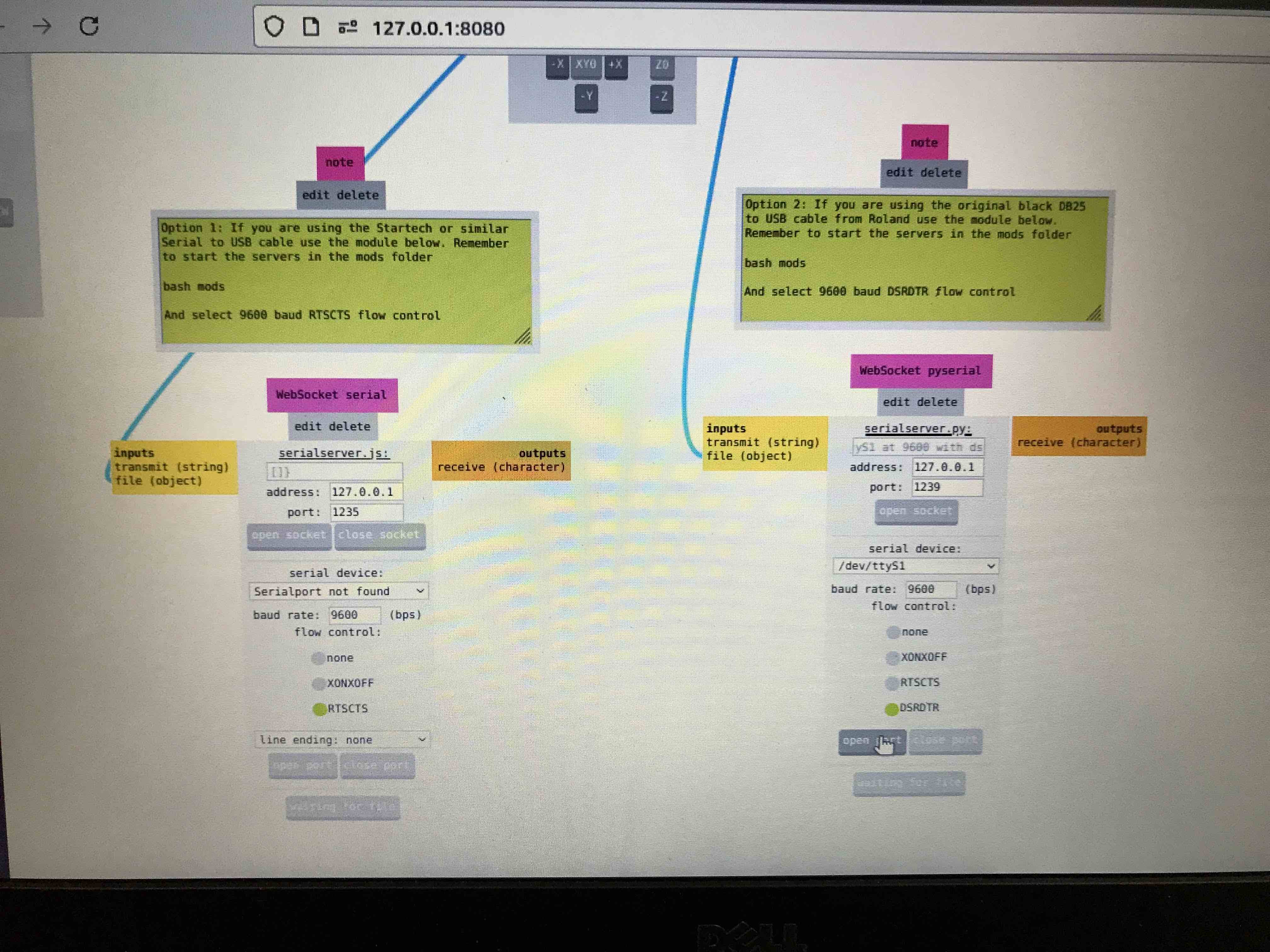
Settings on MODS
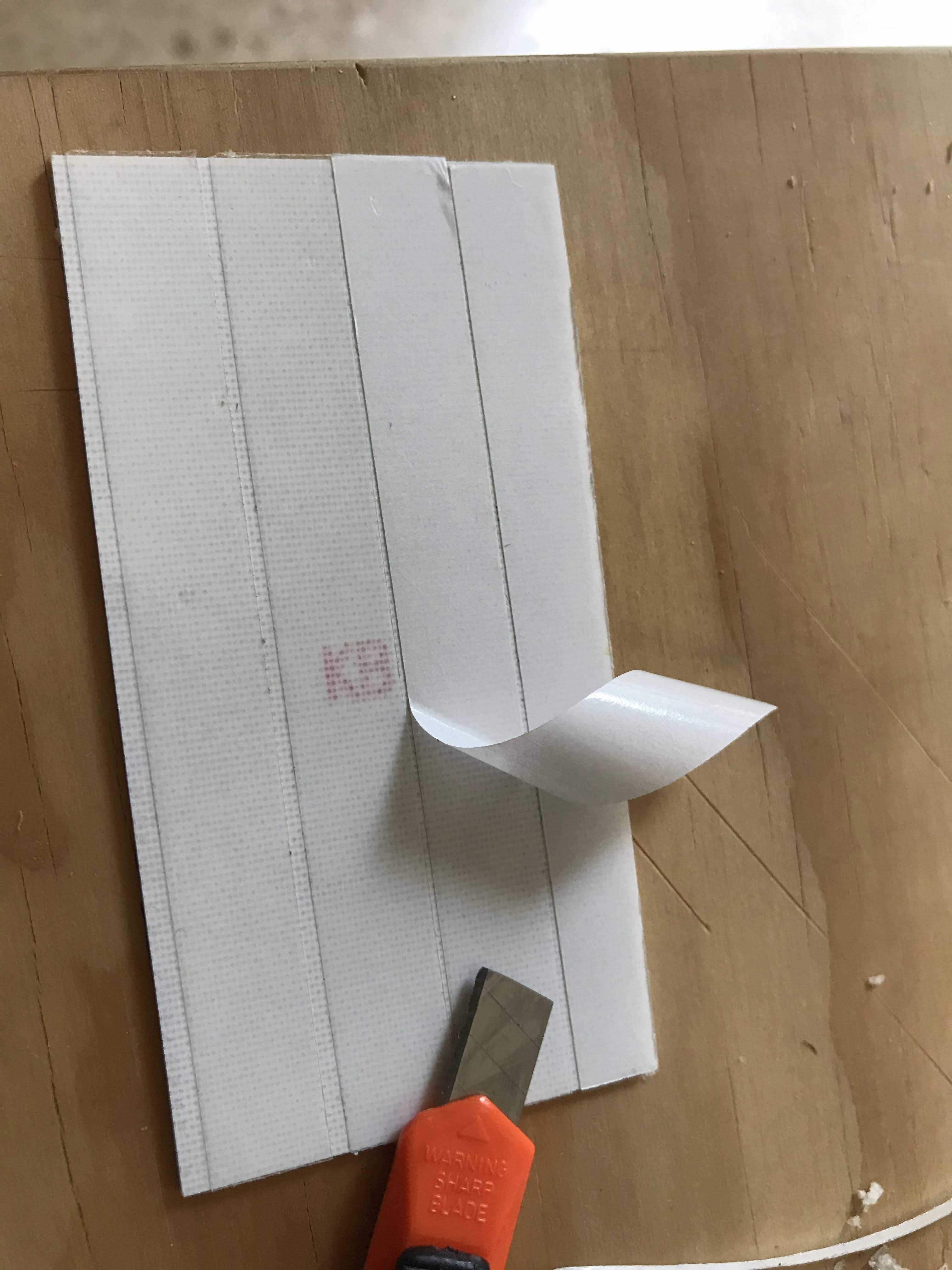
Putting some double
adhesive masking to the coper plate to stick it to the sacrifice
bed
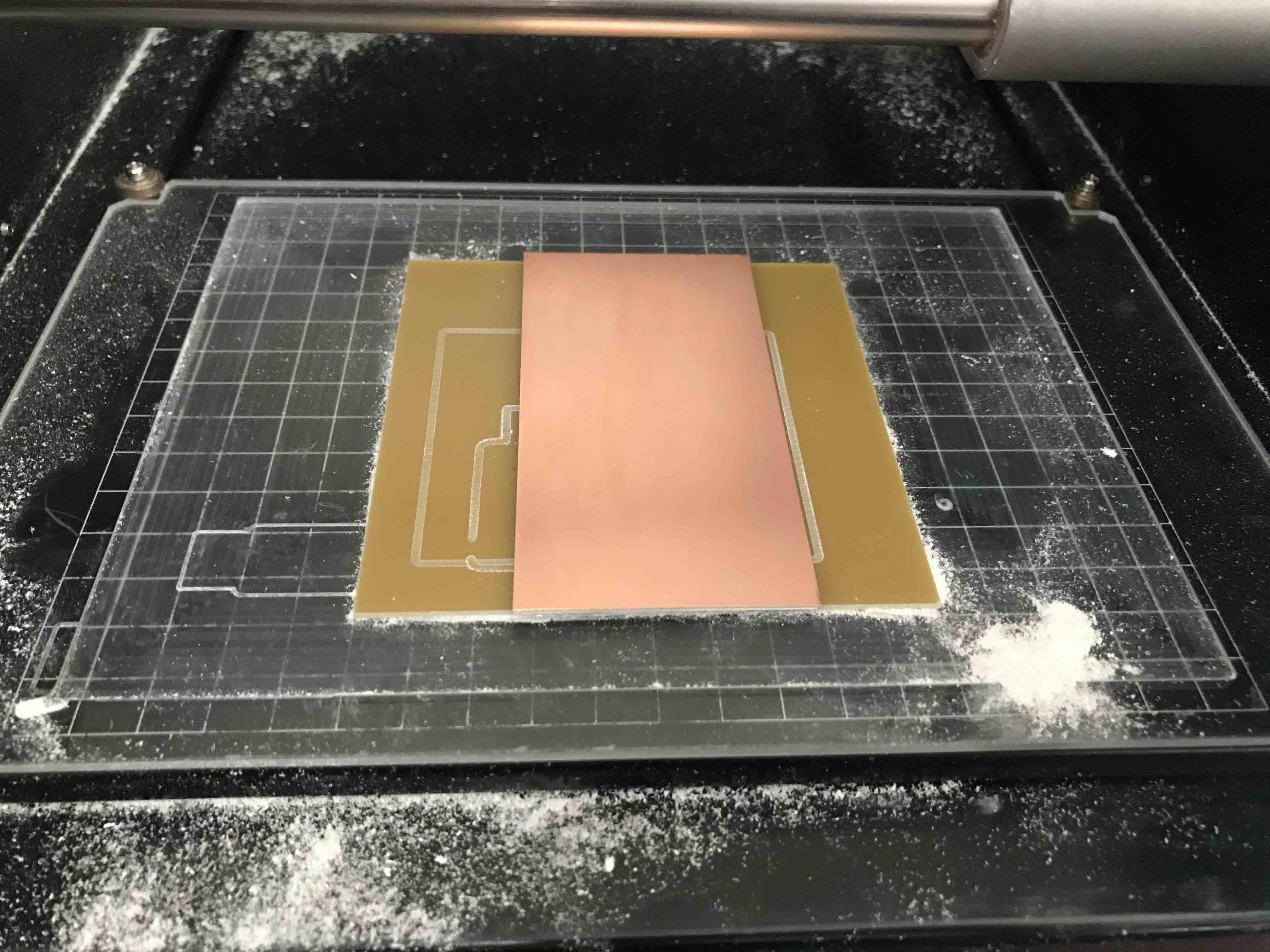
The copper plate
stick to the sacrifice bed
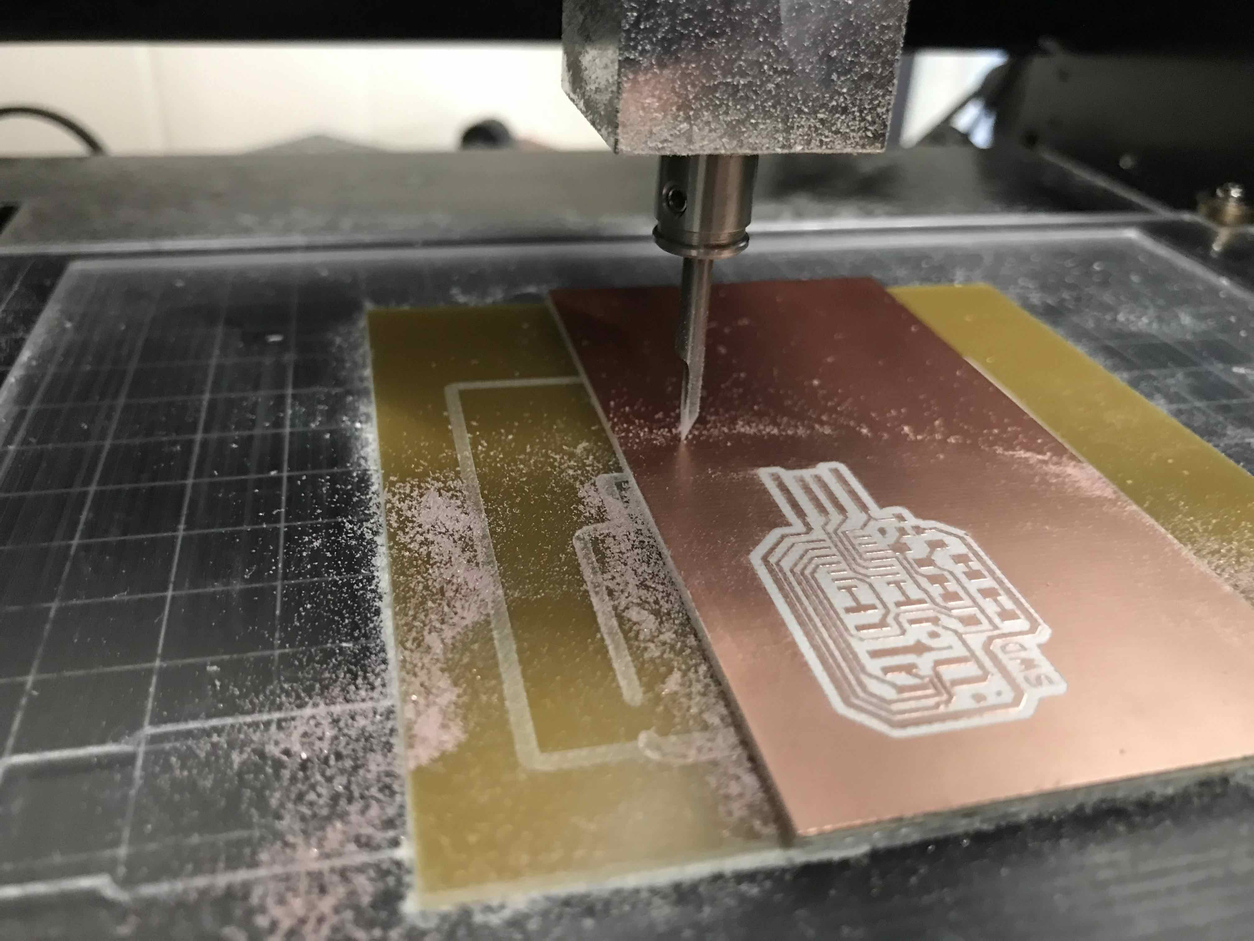
The MODELA just
finish milling my SWD
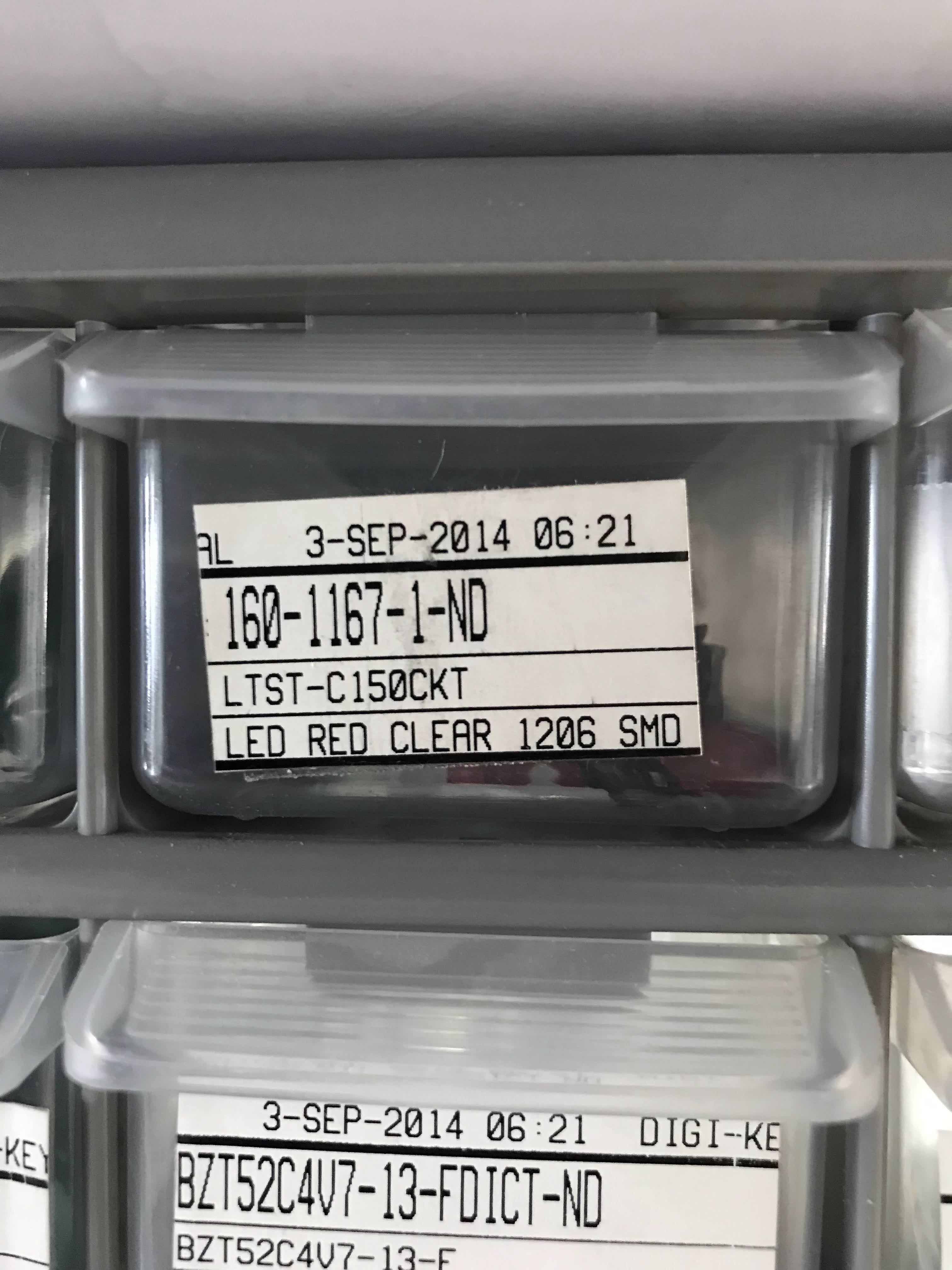
All the components
that our PCBs need are here in little boxes
This PCB is for the
LDR and those are the components I need to put on it
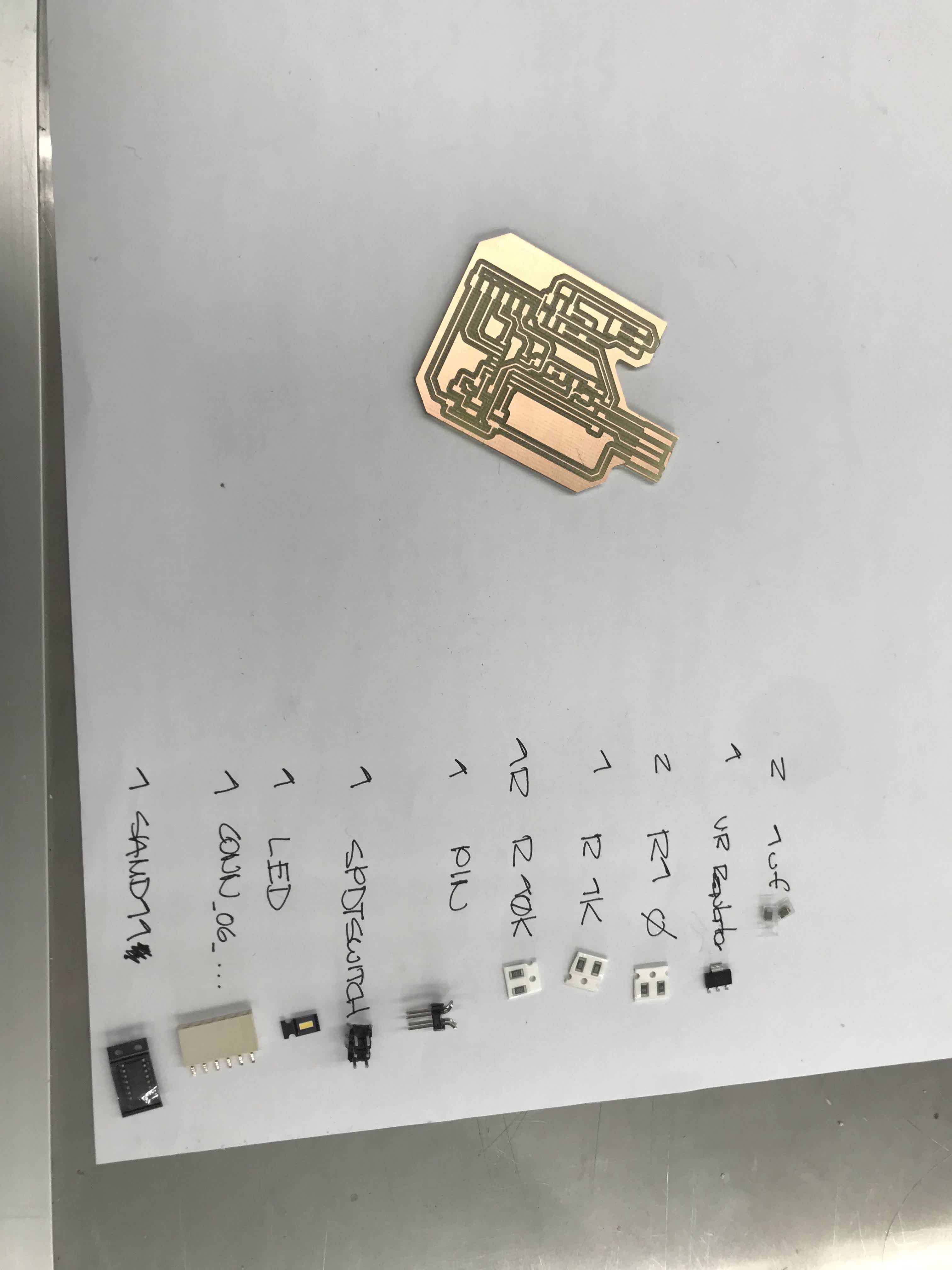
The list of the
components I will weld at my Hugodino board
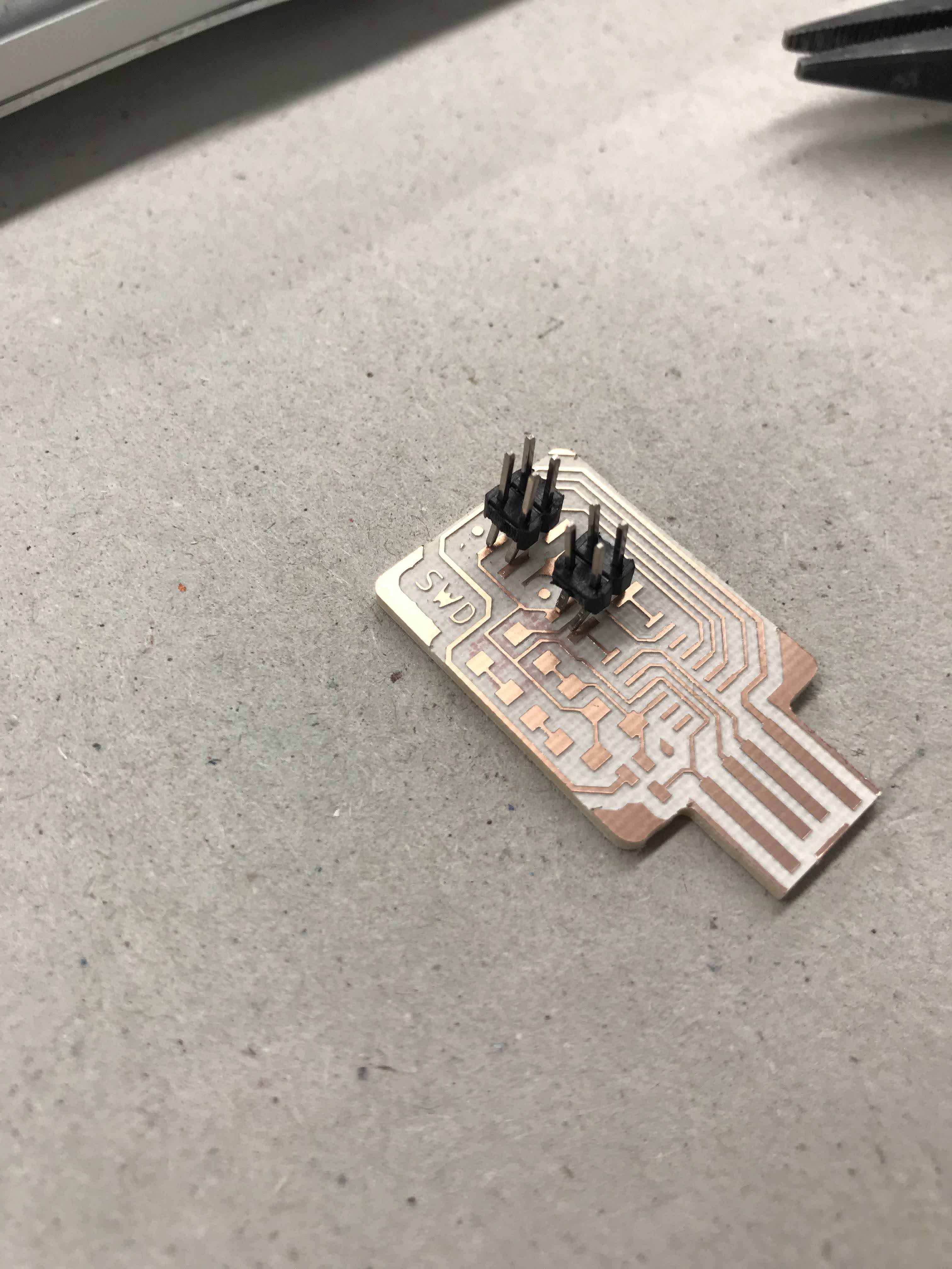
My SWD board
previously to start welding the components
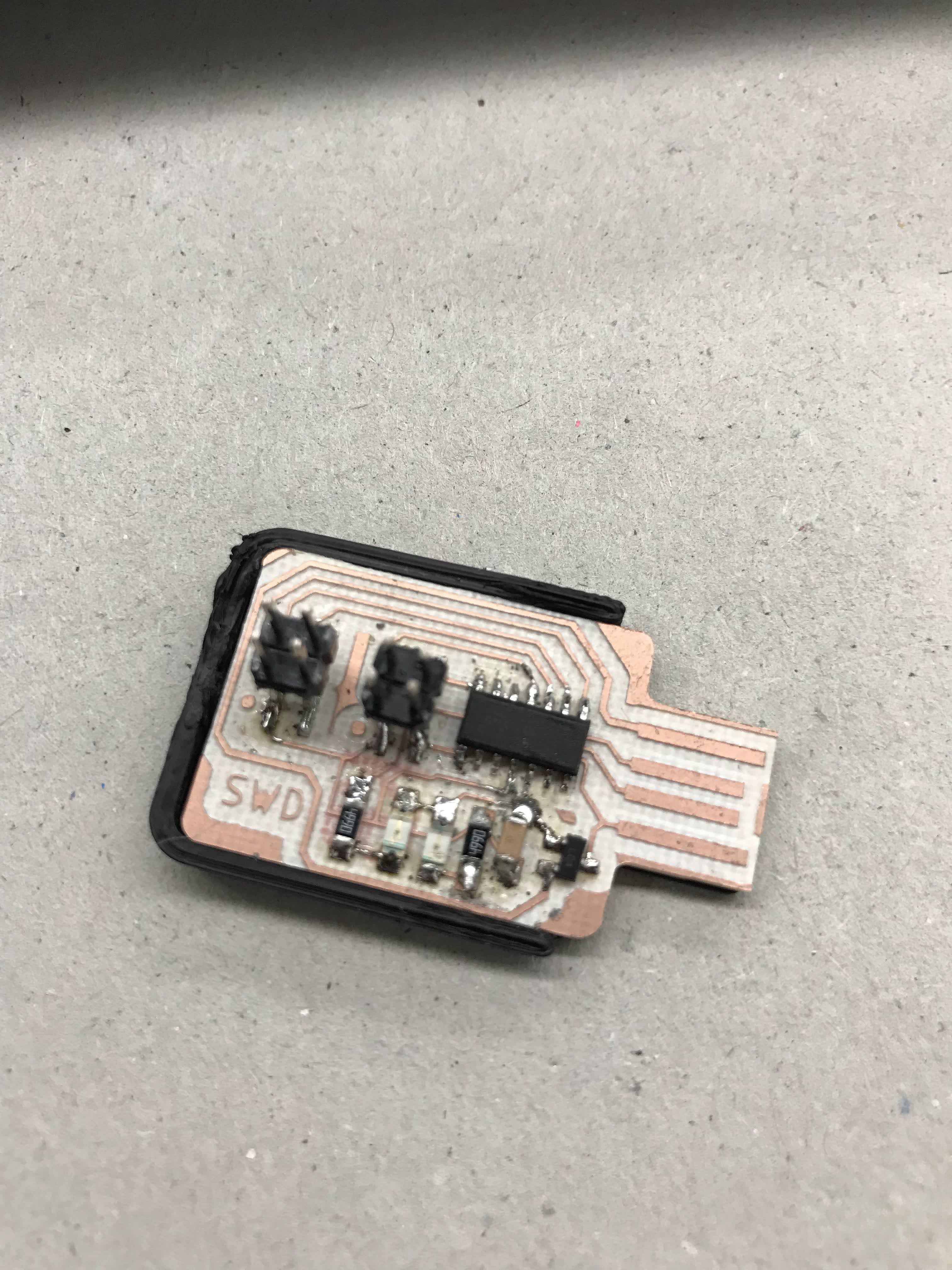
A shot of the SWD
finish, with this I will program my Hugodino board
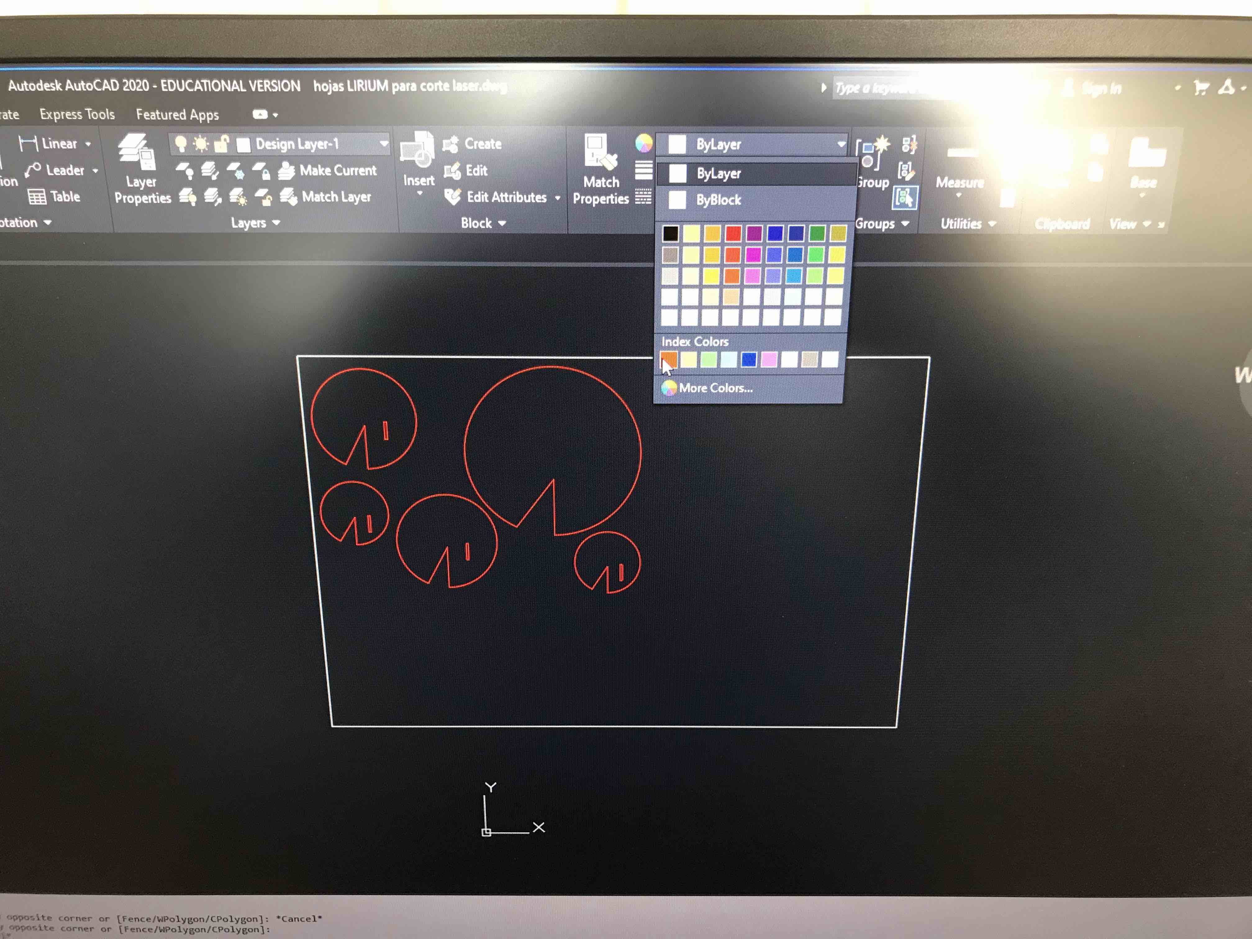
The leafs covers in
Autocad, this drawing is in a DWG format. Here I´m choosing the
color of the layer so the laser machine knows if it is a cut or
just engrave.
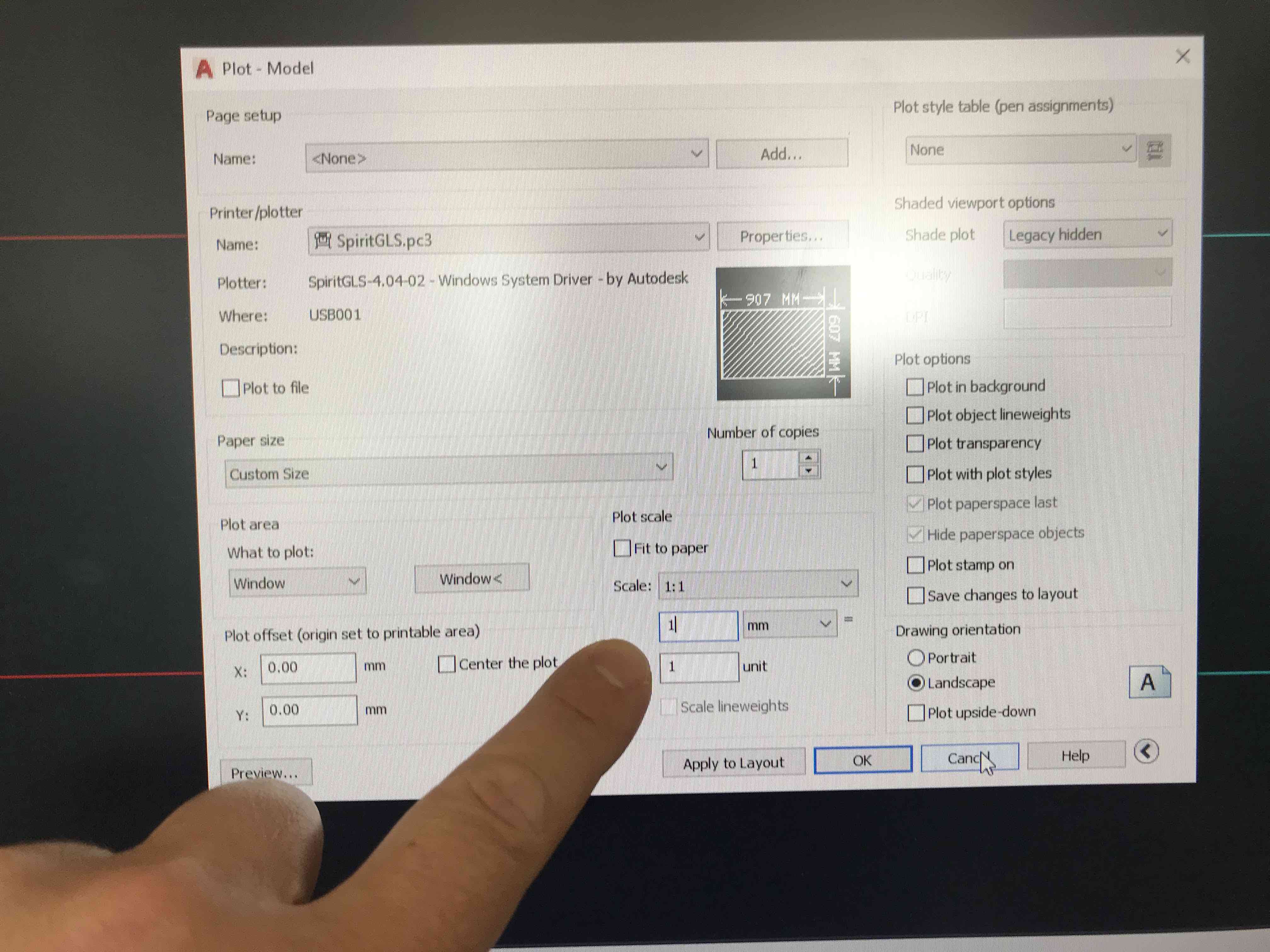
This is the setting
panel of the laser machine, here we put the size, the proporties
and the scale
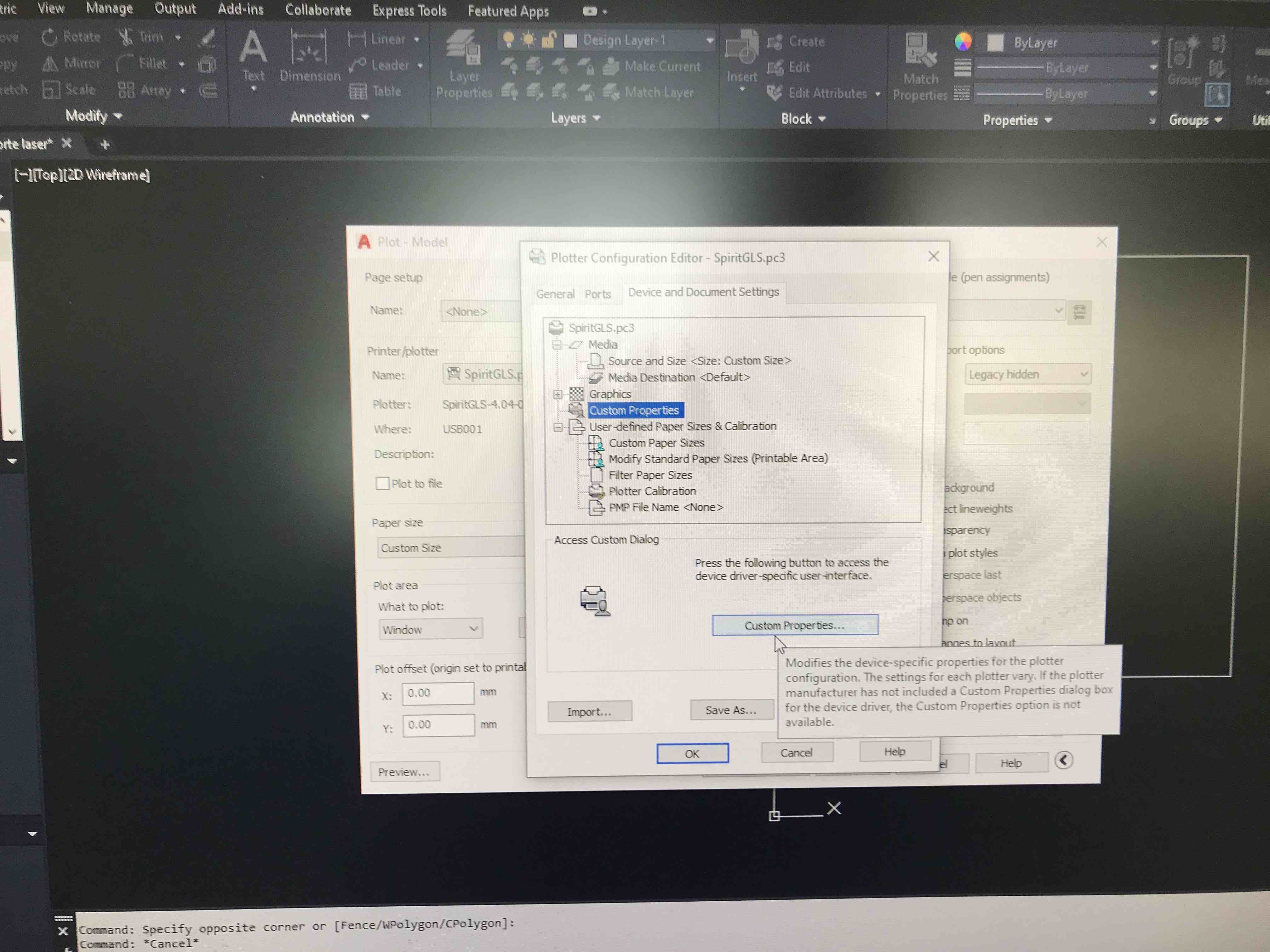
The custom
properties initial panel
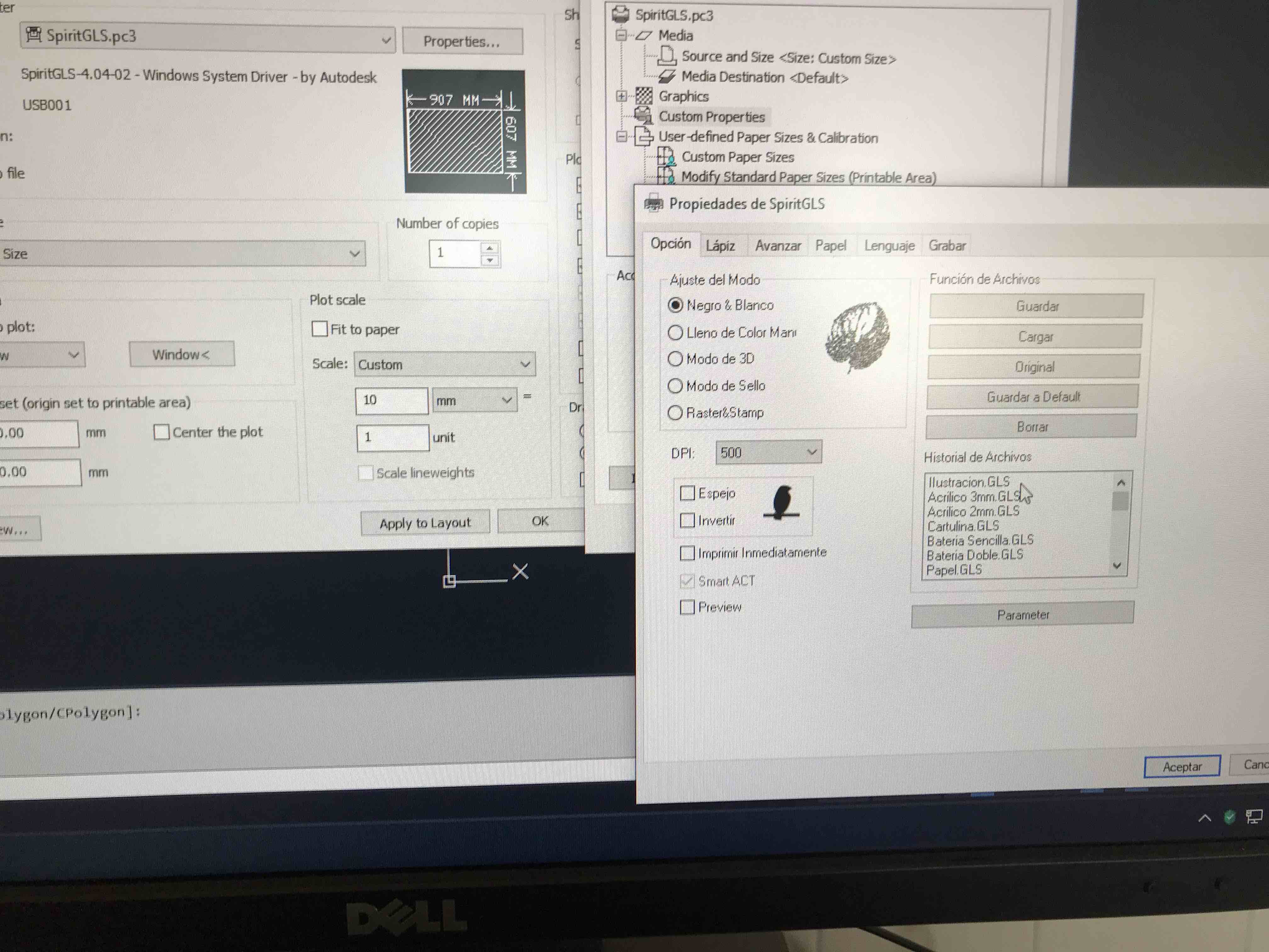
Here I´m going to
select the material that I´m about to cut, in this case is
"cartulina ilustración" or ilustration board.
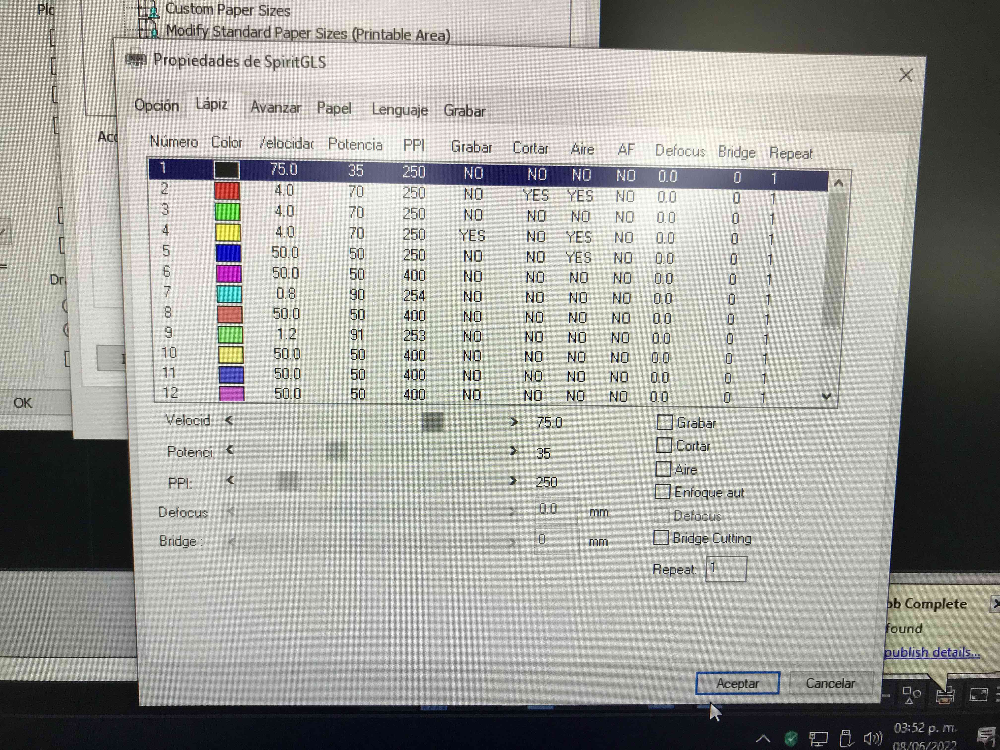
This must match the
layer color I choose in order to cut or engrave, in this case
the red color will cut with a 75mm speed and a 35 of power
settings
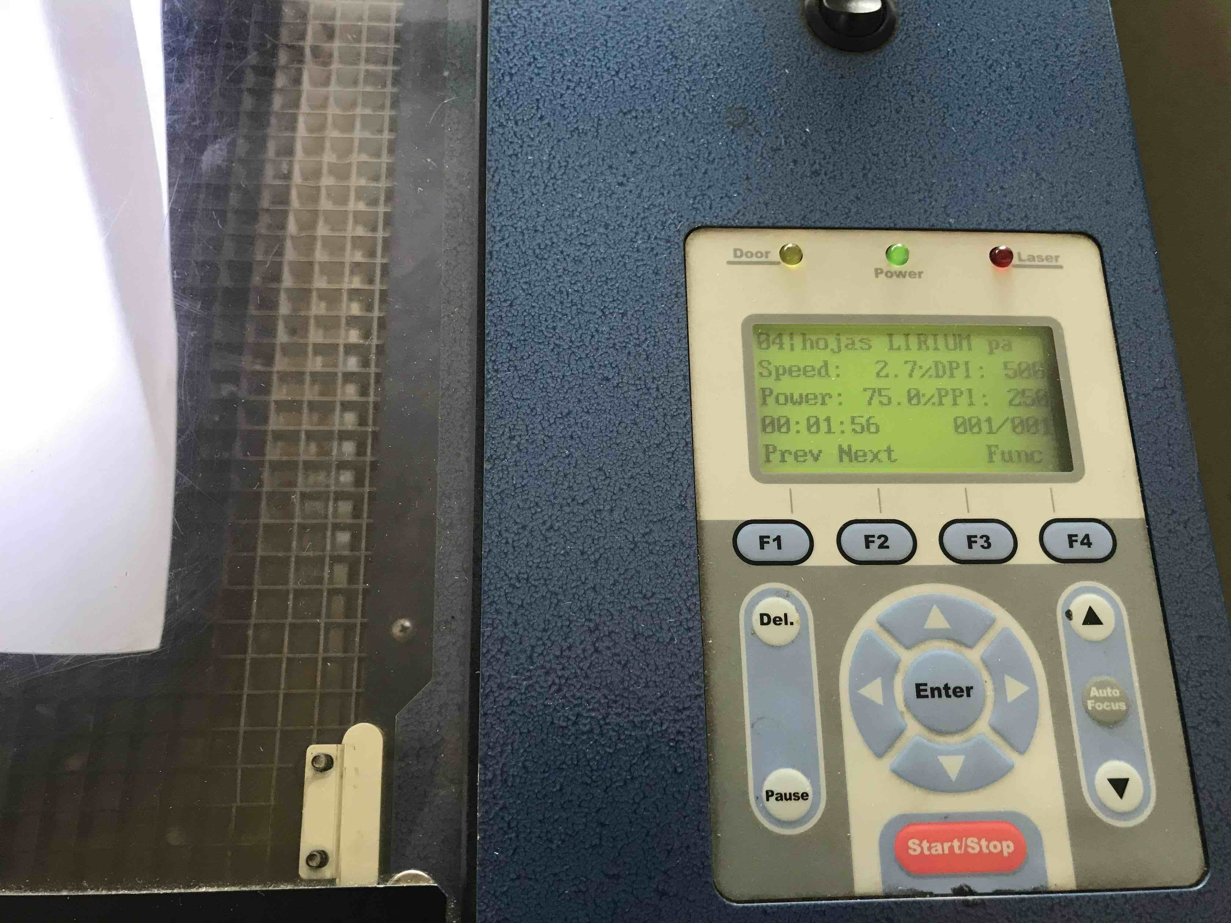
Laser machine
display, here we can see the name of the archive display and we
can select different functions like level up or down the
material in order to had the right separation between the laser
nozzle and the material.
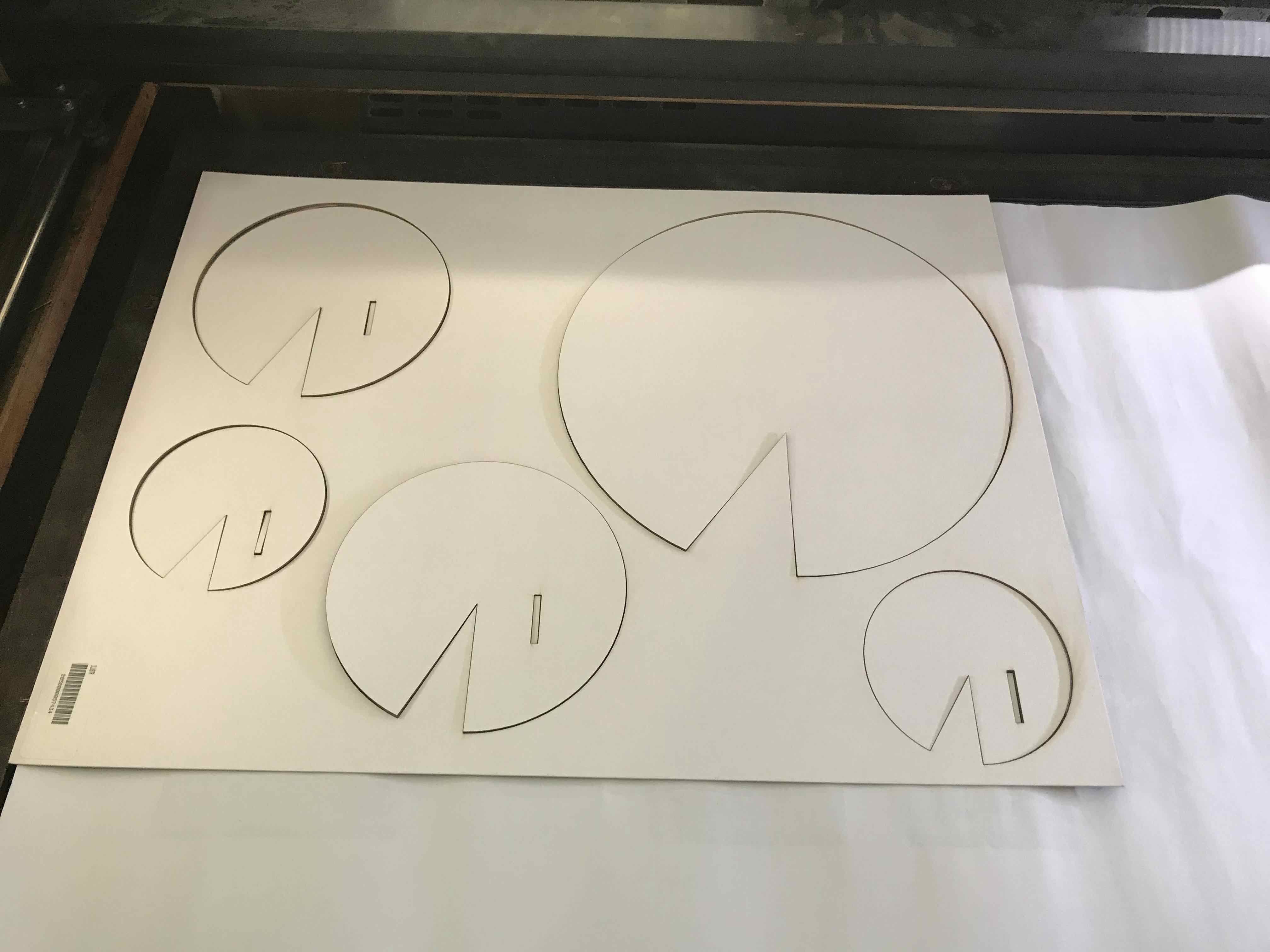
My pieces already
cut, it is recomend to put some paper below the cardboard to
protect the downside face of our pieces.
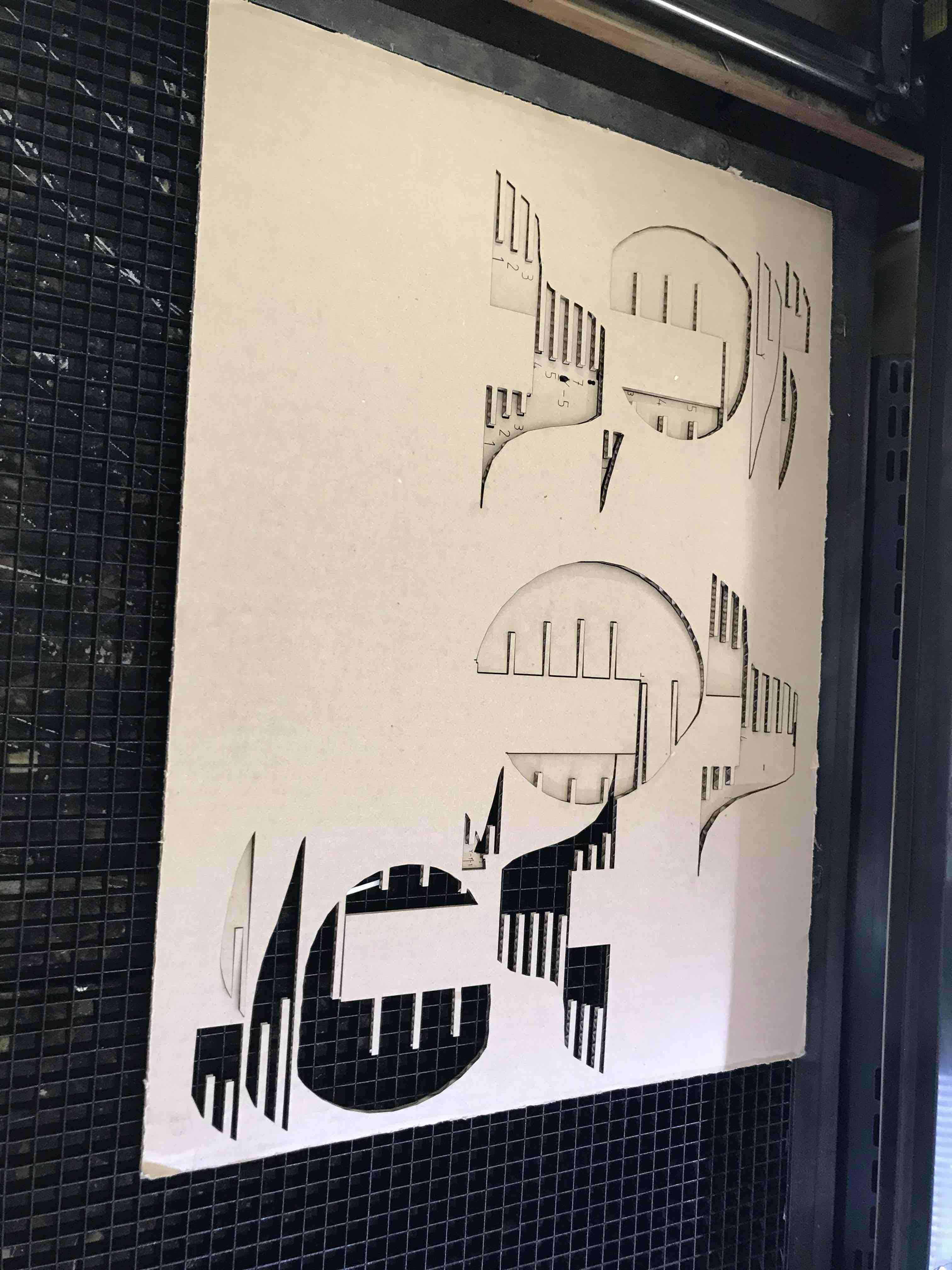
Some of the base pieces
that also were cut in the laser machine
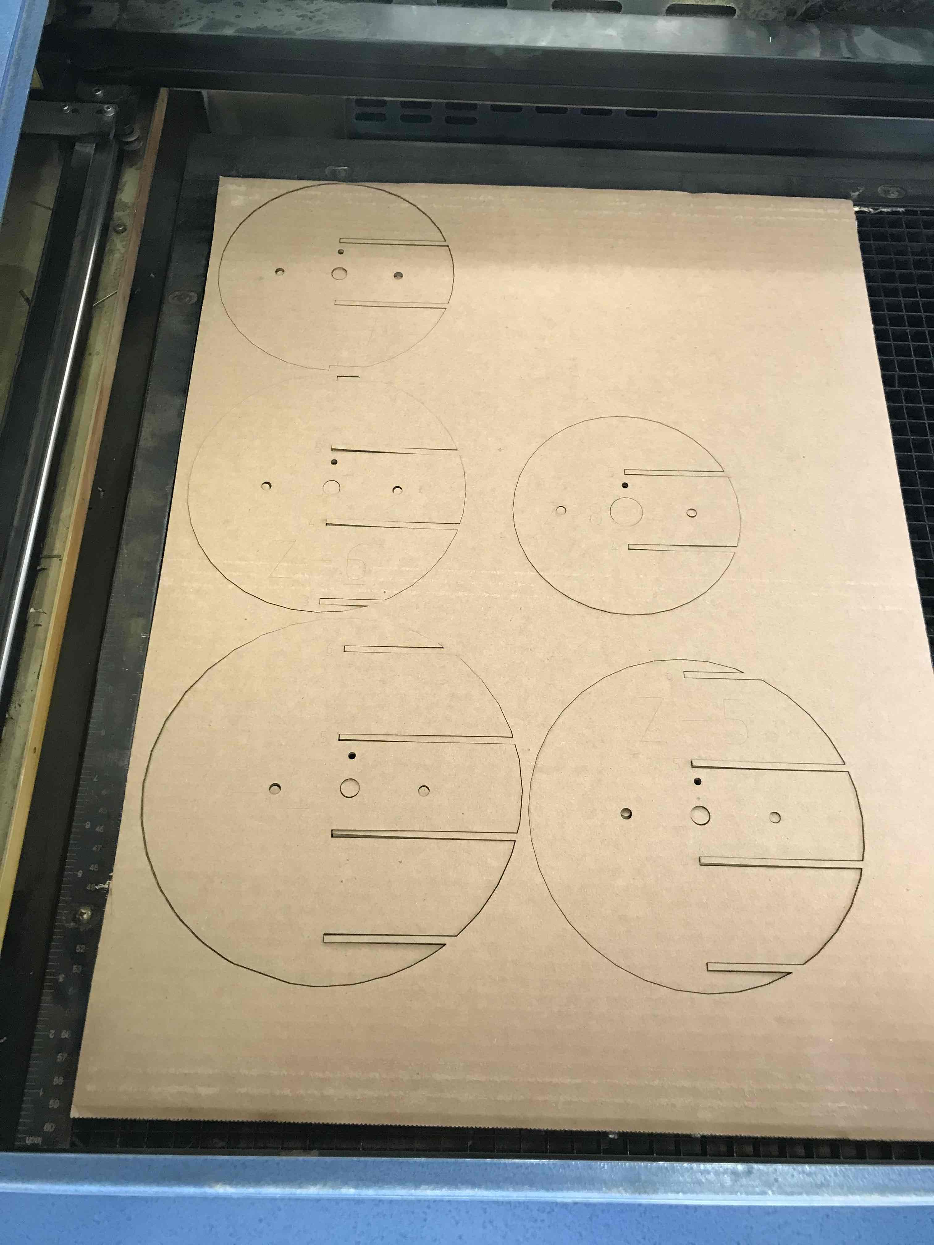
the "Z" pieces that
fit in the base, al the pieces has a "code" number so you know
in wich place they fit.
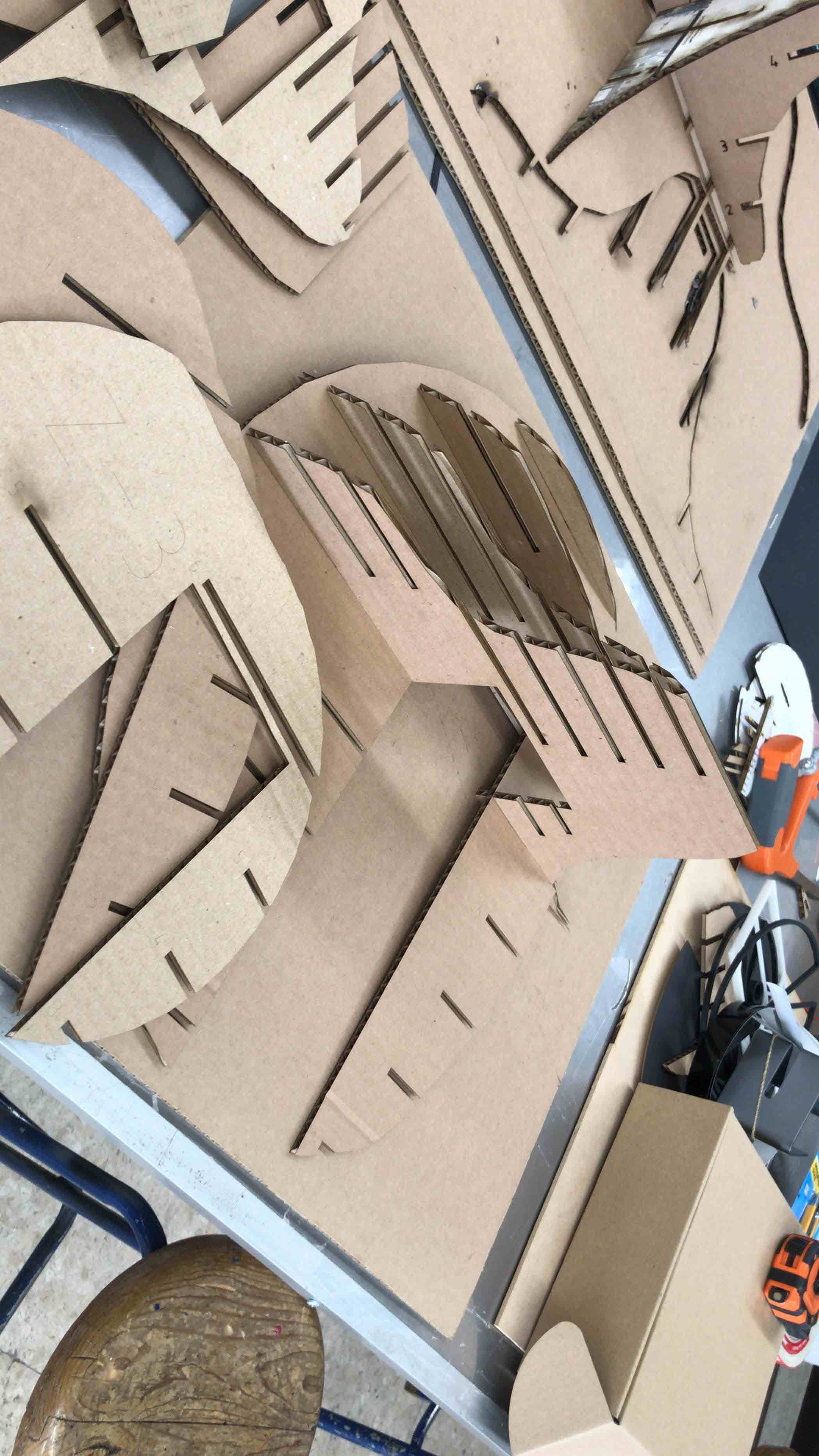
More cardboard
pieces
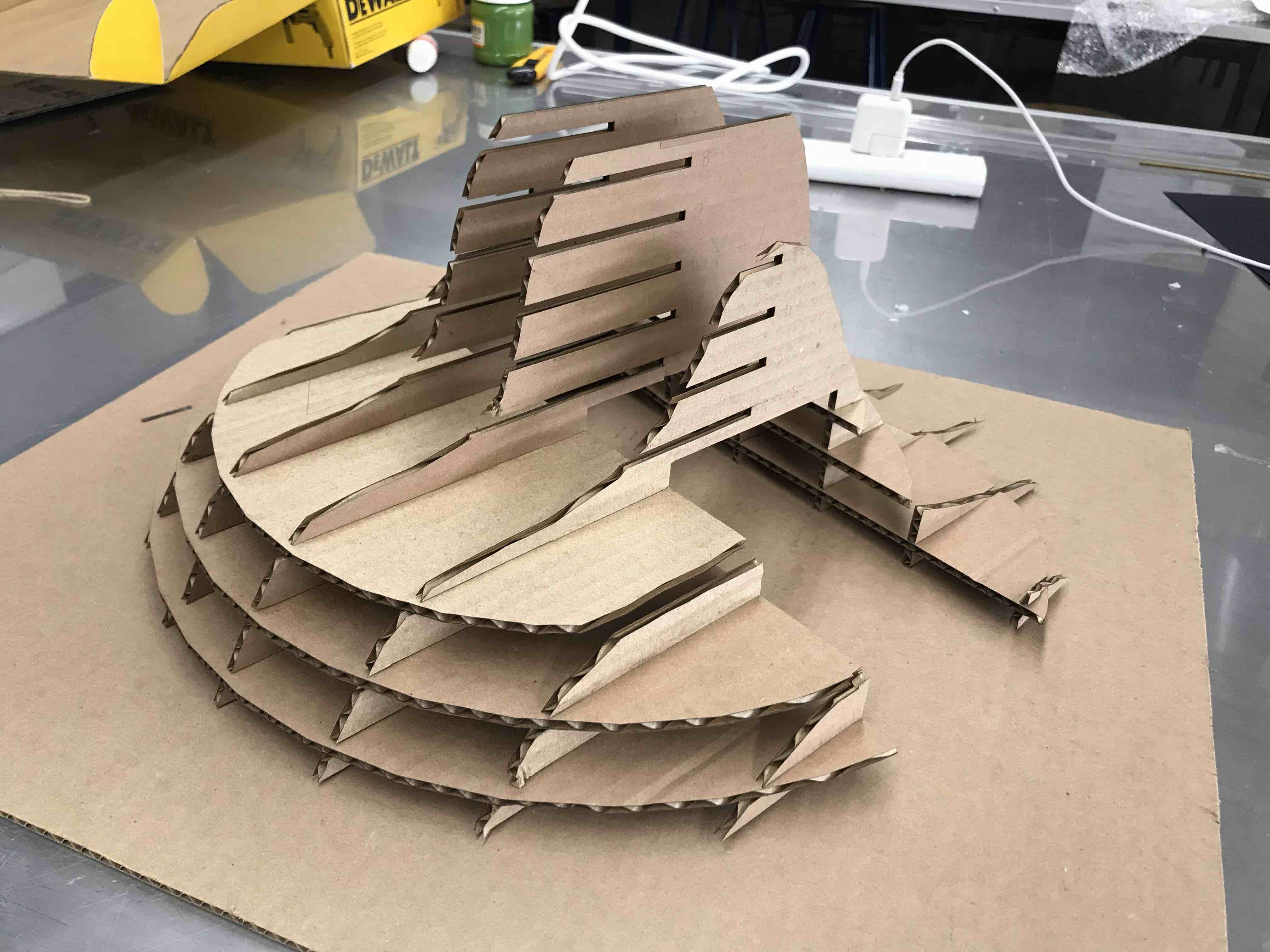
Te base almost
finish with the cardboard pieces
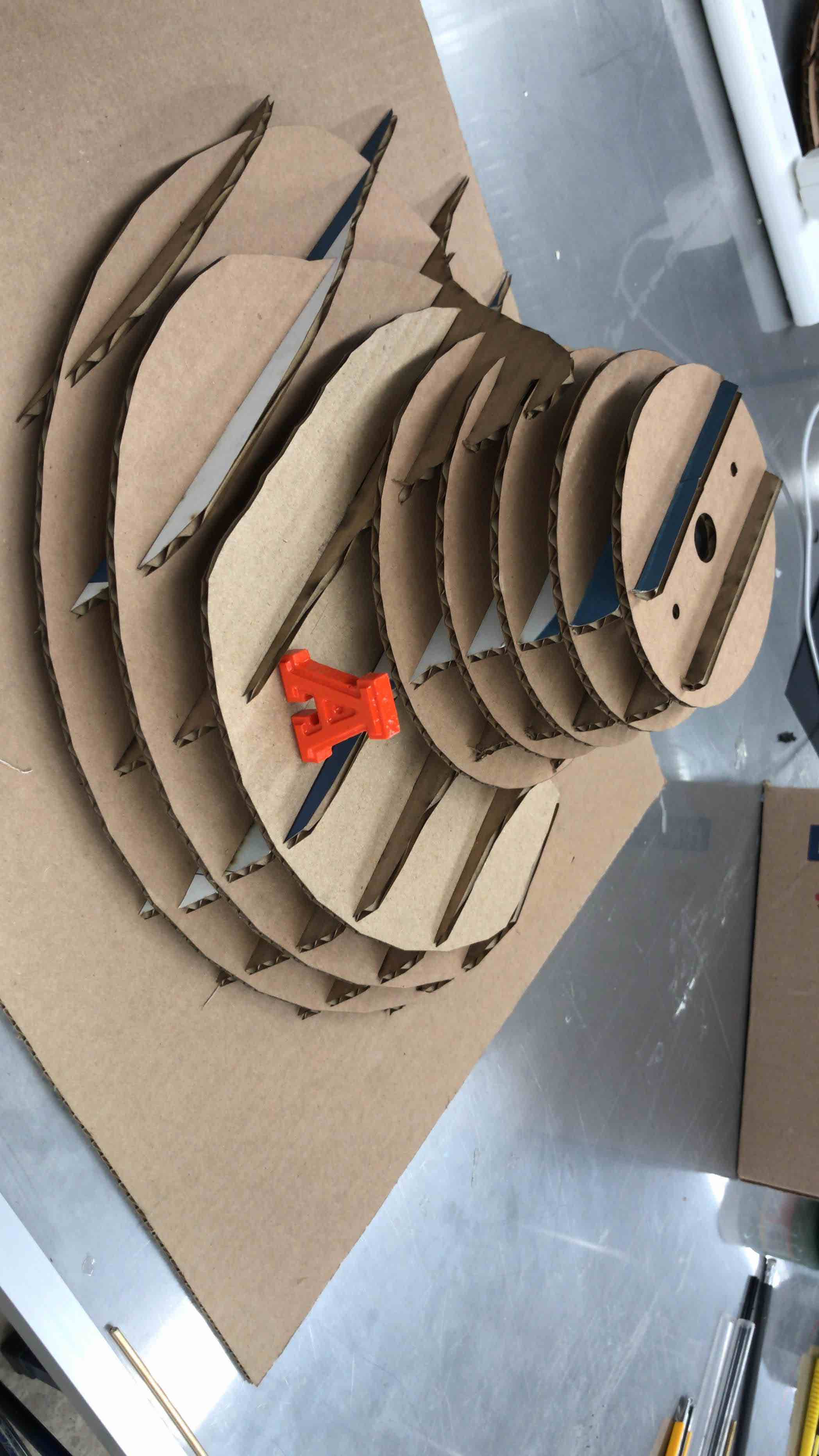
All the pieces
of double corrugated cardboard that forms the base in
place
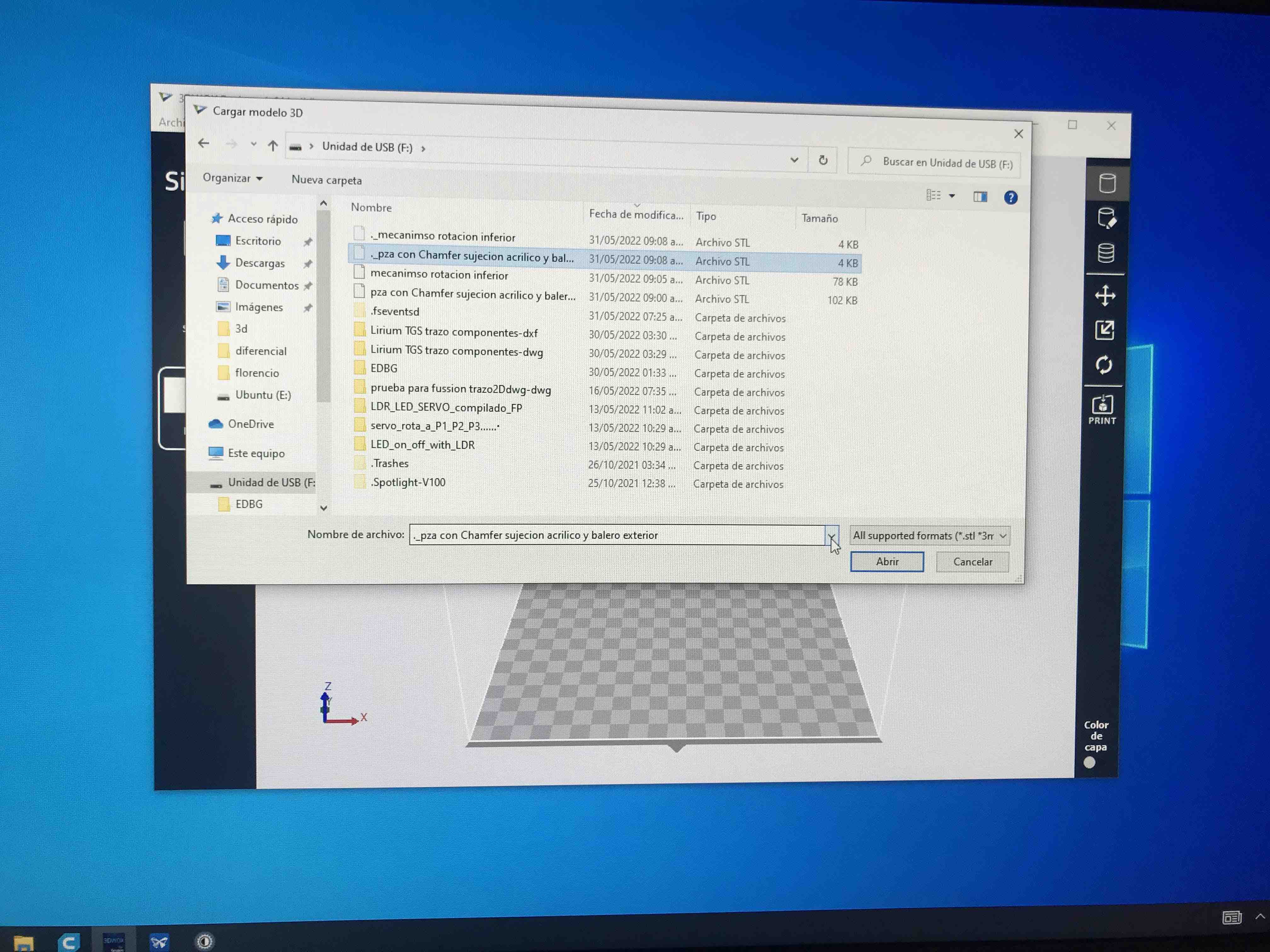
once you have your
object ready to print, export it in .STL format, so you can
import it to the 3D printing machine software without problem.
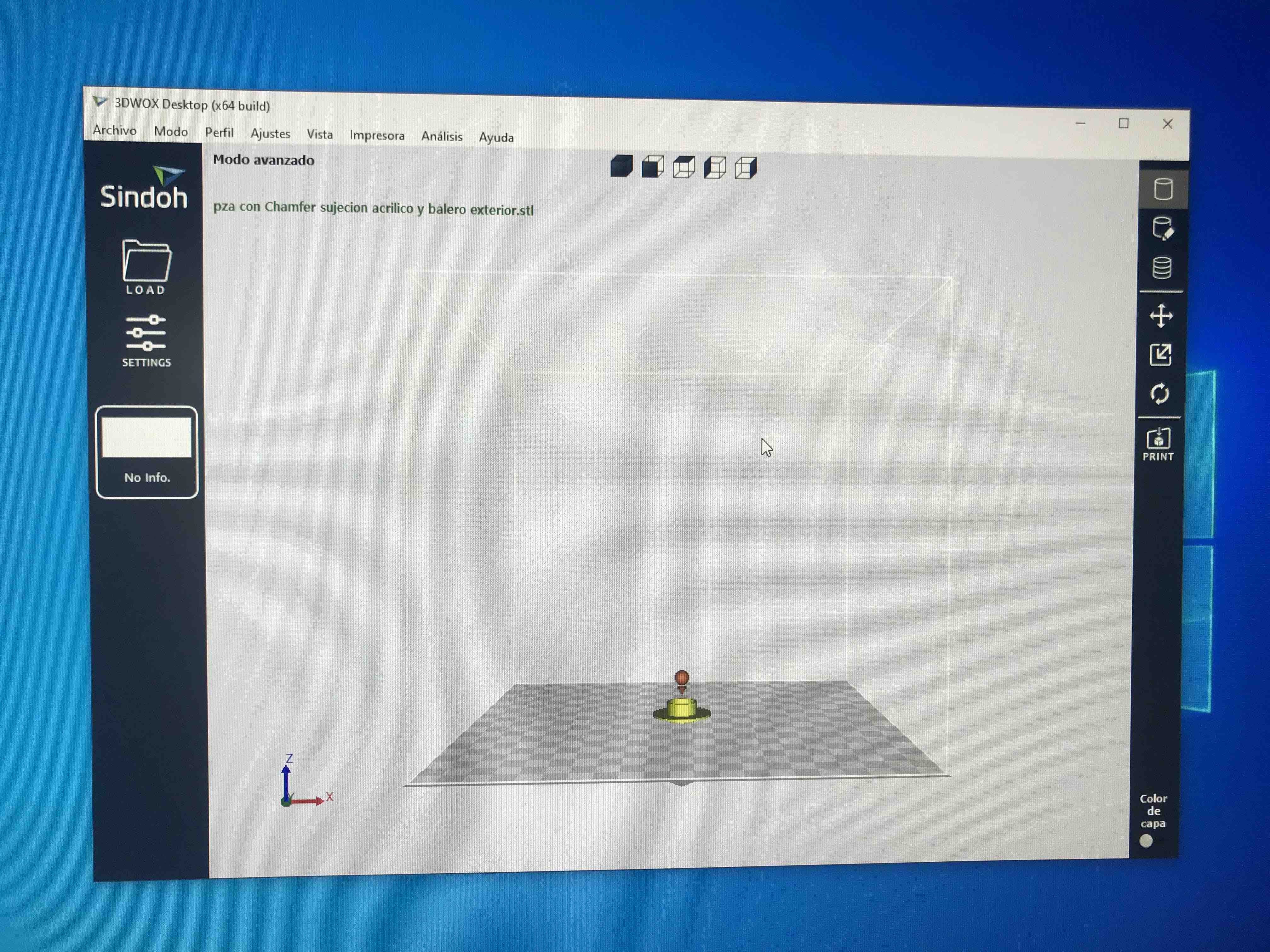
Sample of one
object imported.
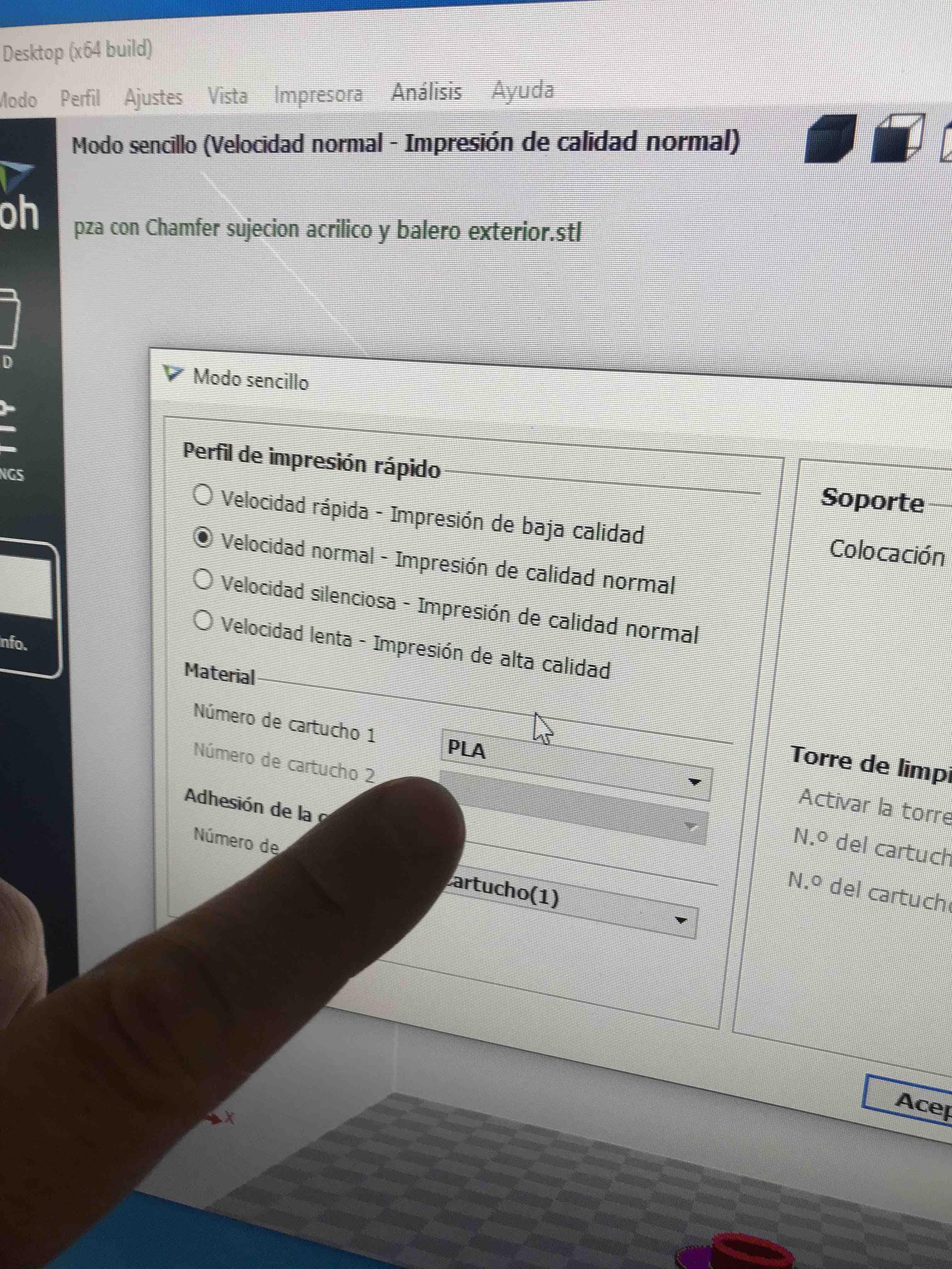
When in Advance
settings, first, be sure to choose the right material, in this
case could be ABS or PLA, then you can set up the support, the
layer thickness, the speed in general or for the outside or
inside face of your object.
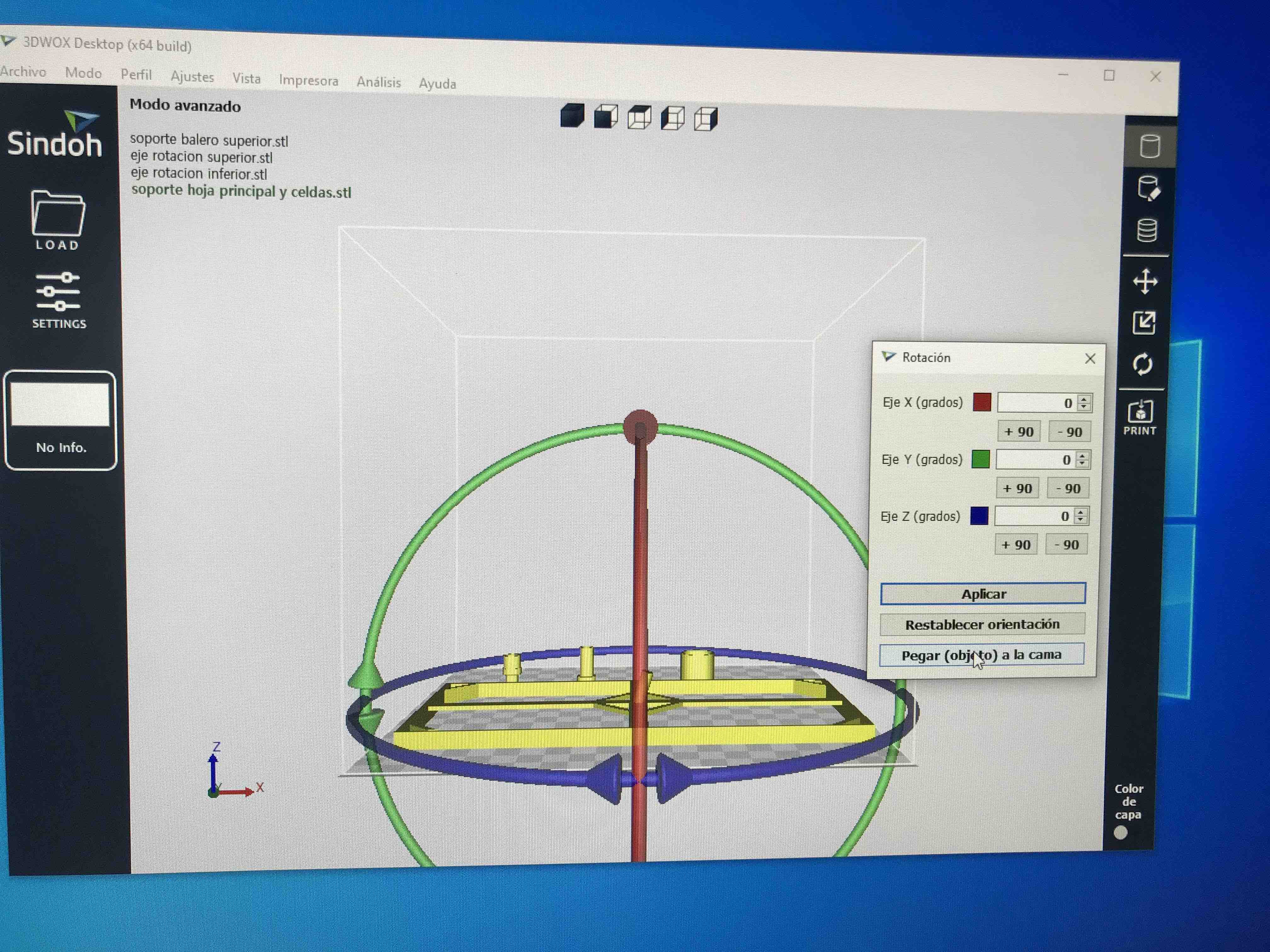
If you need to
rotate the object into a better position to fit better the print
process you can do it with the rotation menu in X, Y or Z Axis
and you can dcecide the angle need it and then you can click the
Stick object to bed to be sure it is in the right position.
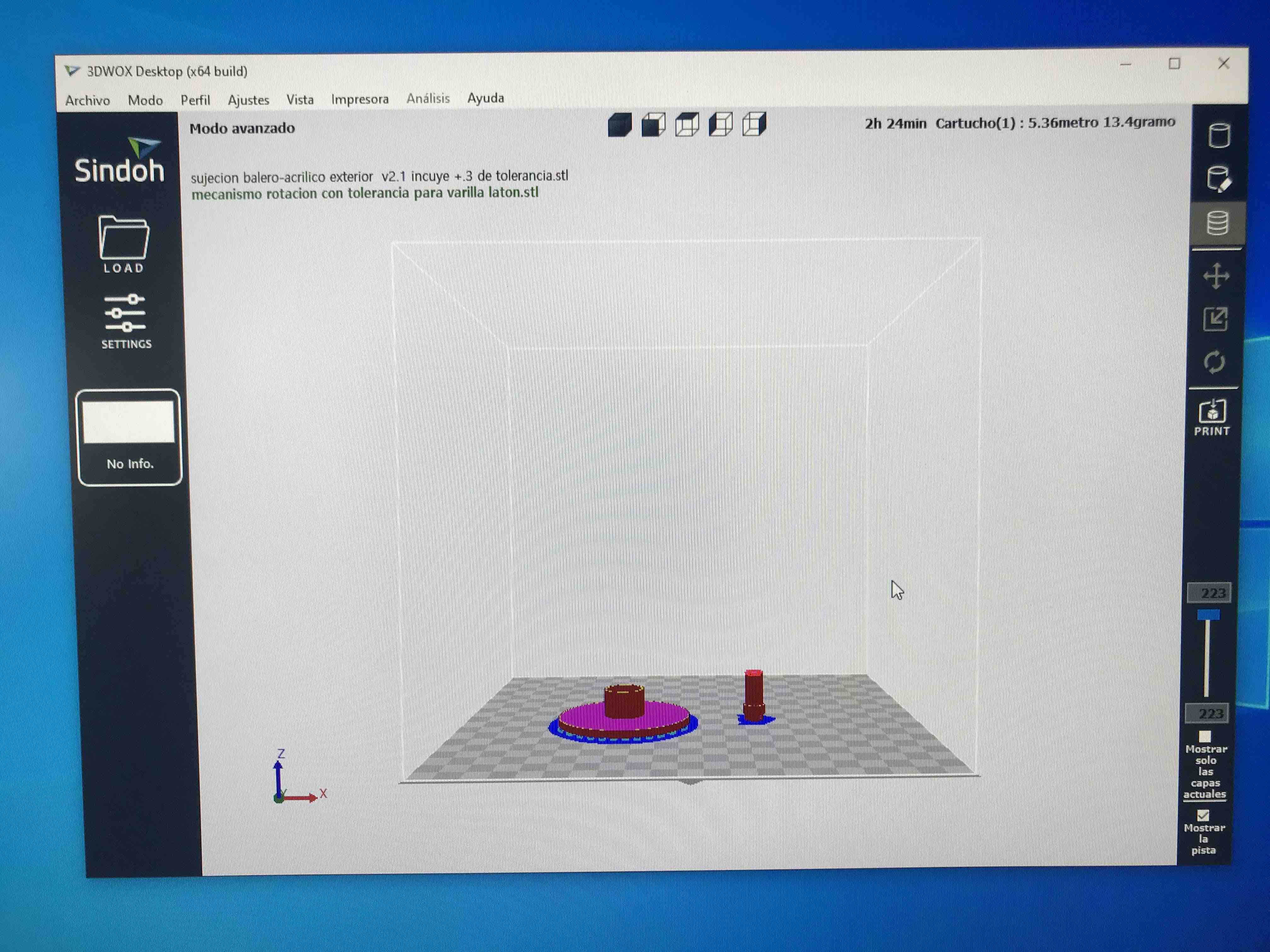
The Gcode is
already export and in this screen you can se the printing layers
with the slide that you can find at the right of the screen, the
one who has the 223 number, you can go up or down.
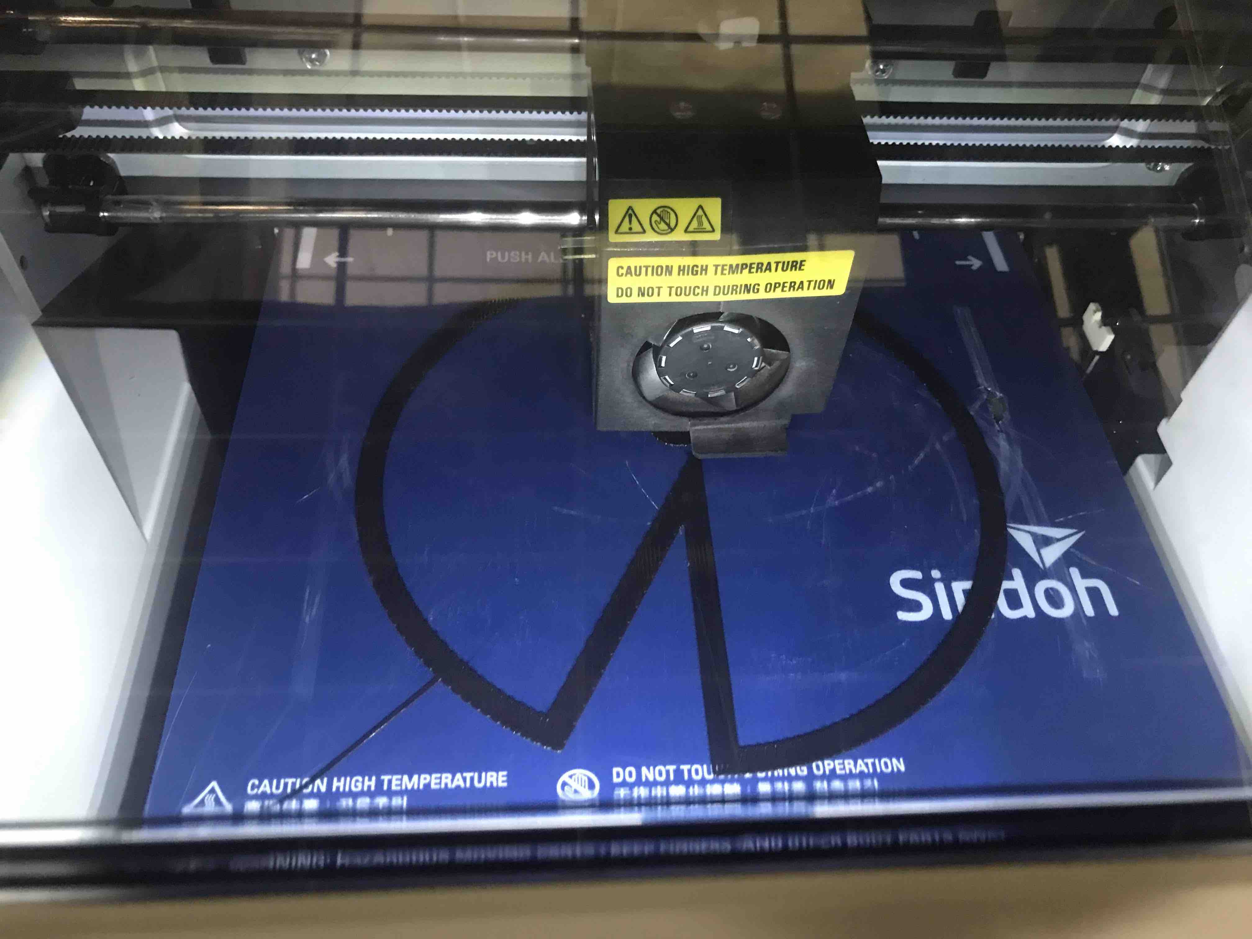
Here you can see
that is printing the support that atache the object to the bed
of the machine, over this will start to print your final piece
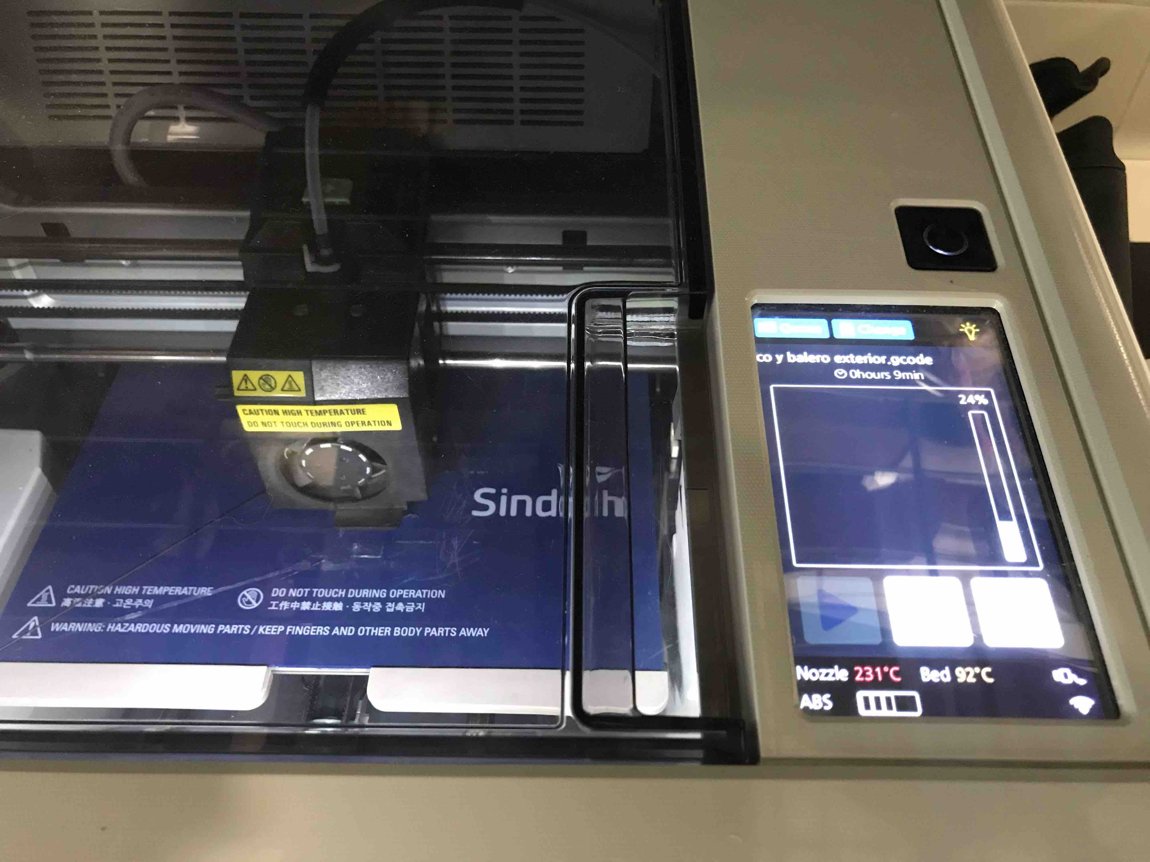
Once printing just
wait and from time to time just check if everything is fine.
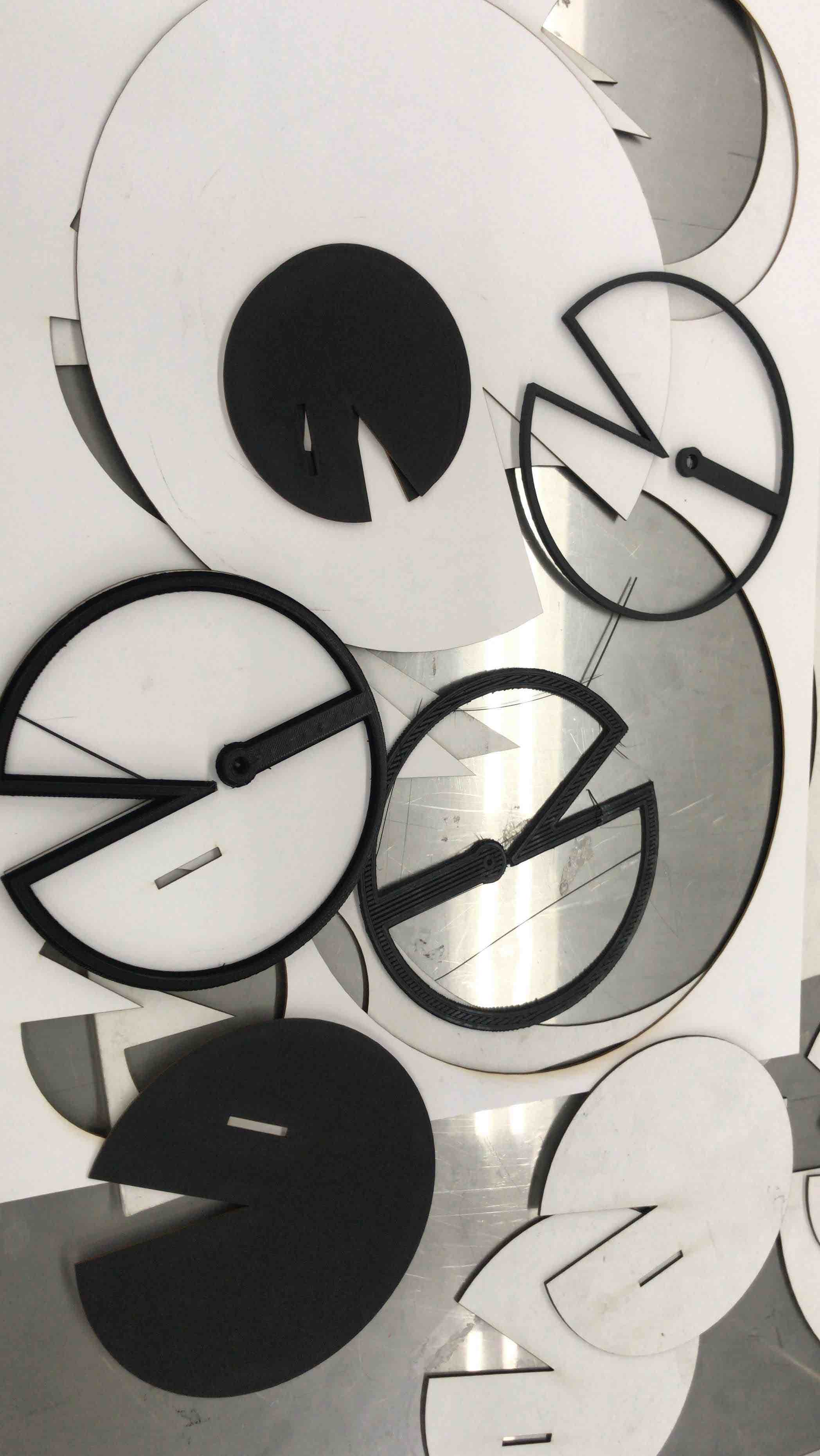
Cardboard leafs and
the perimeters printed in 3D some in ABS and others in PLA. I
did this to check settings, printing time, texture and quality.
The axis of
rotation and the solar cells support printed in 3D
electronics
a place to re-connect
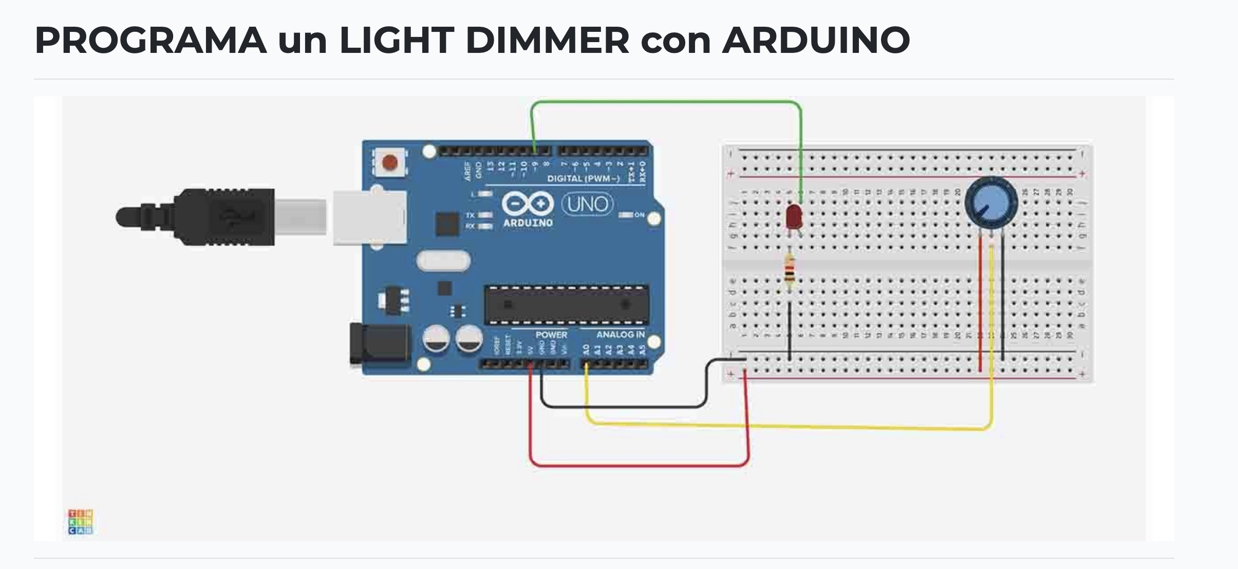
first Ilook for the
schematics of Arduino for the Servo and the LEDS with LDR to start
to do some programming and test the variables of the code
first Ilook for the schematics of Arduino for the Servo and the LEDS with LDR to start to do some programming and test the variables of the code
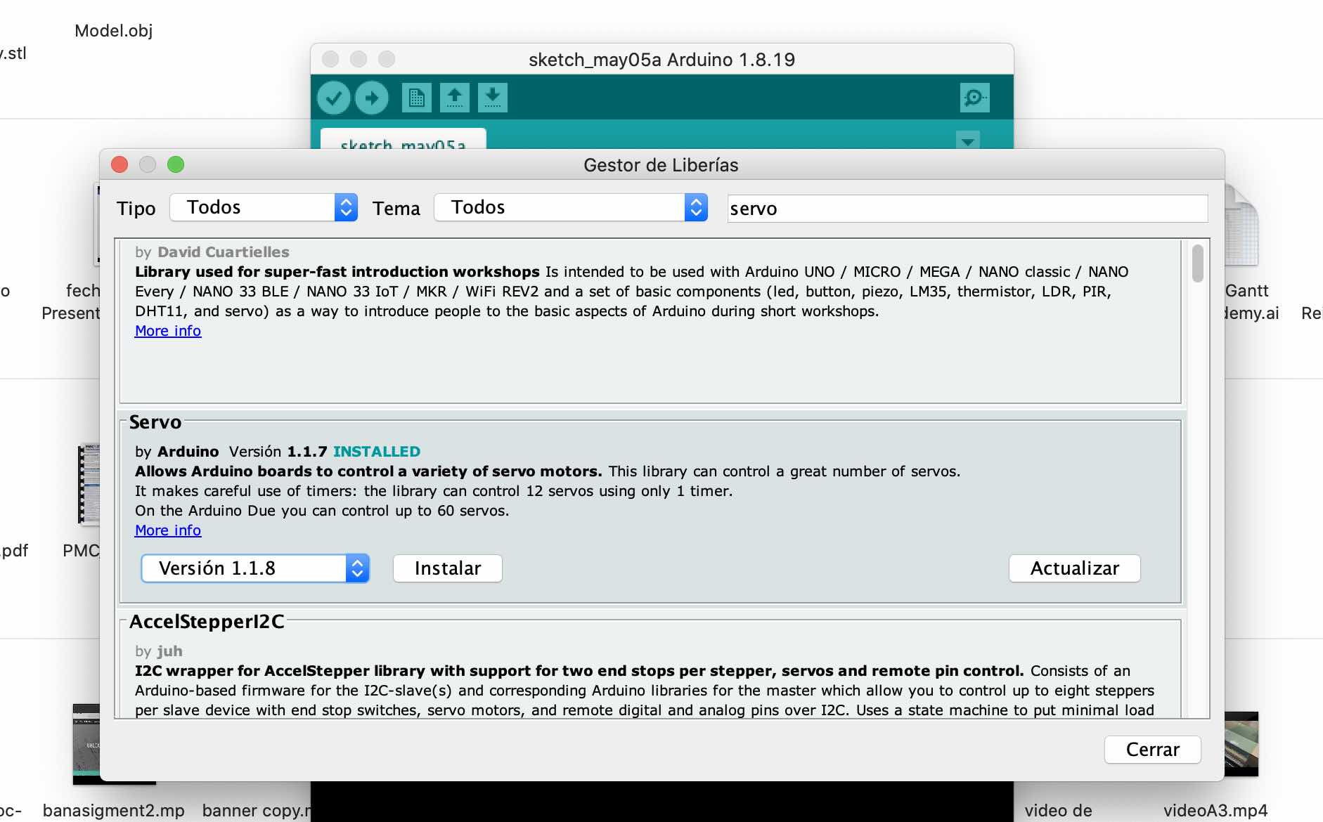
Then I look and
install the libraries missing for the servo
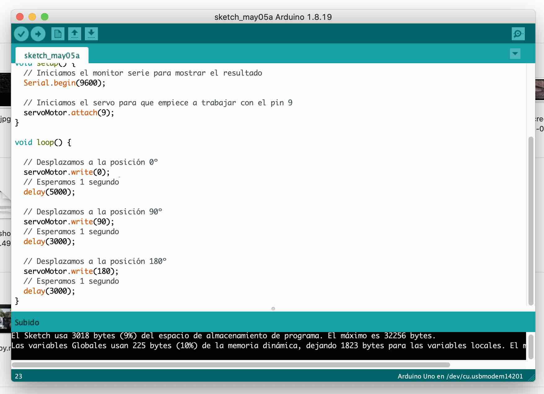
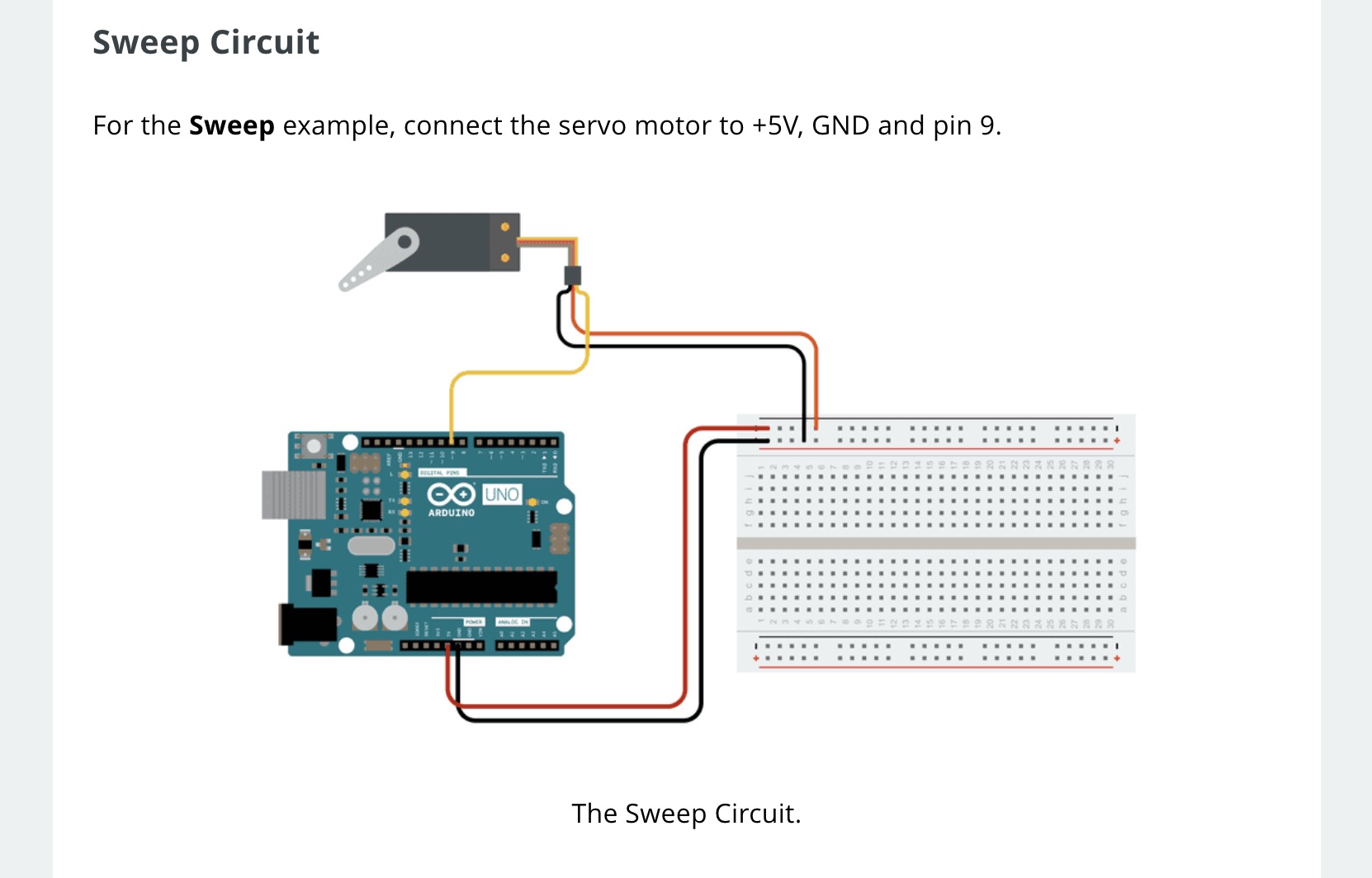
Here´s a code that
moves a Servo motor in different degrees, thats just what I need
for my project.
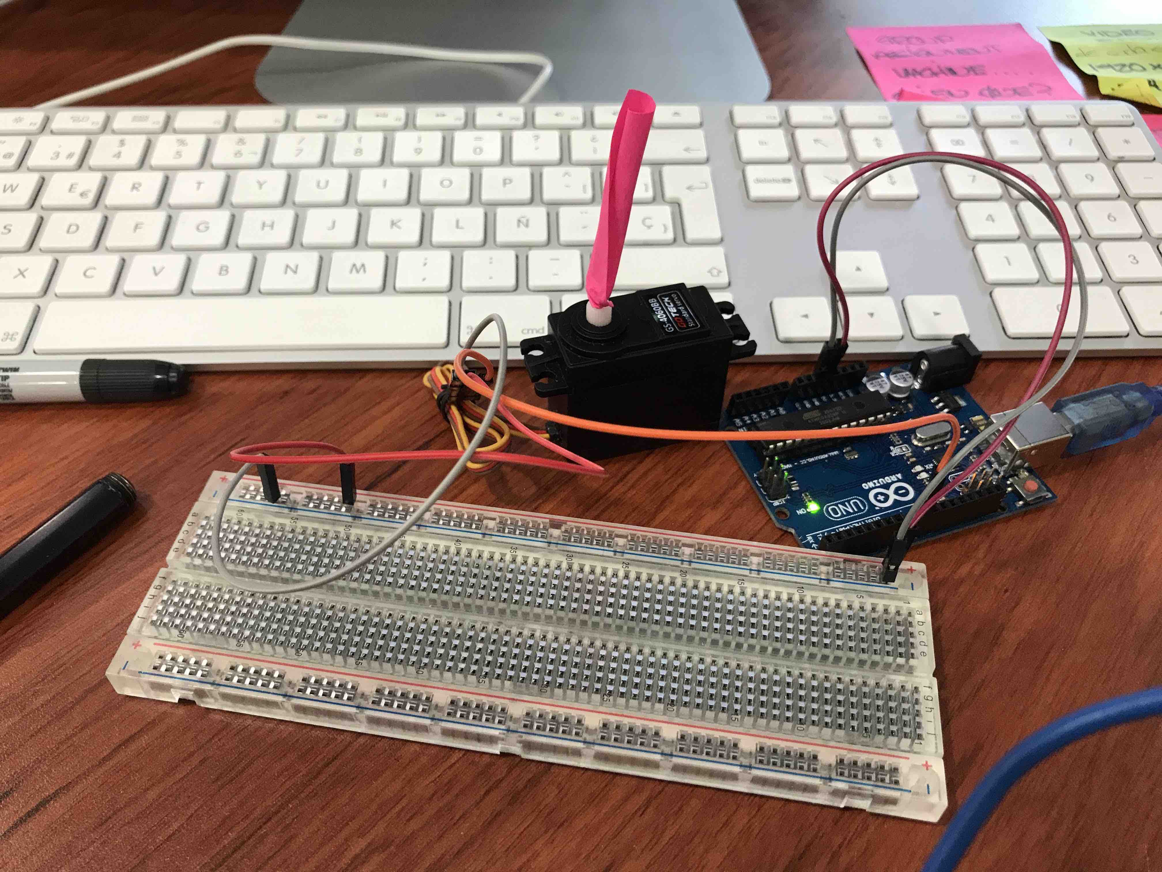
And works well, it
was easy
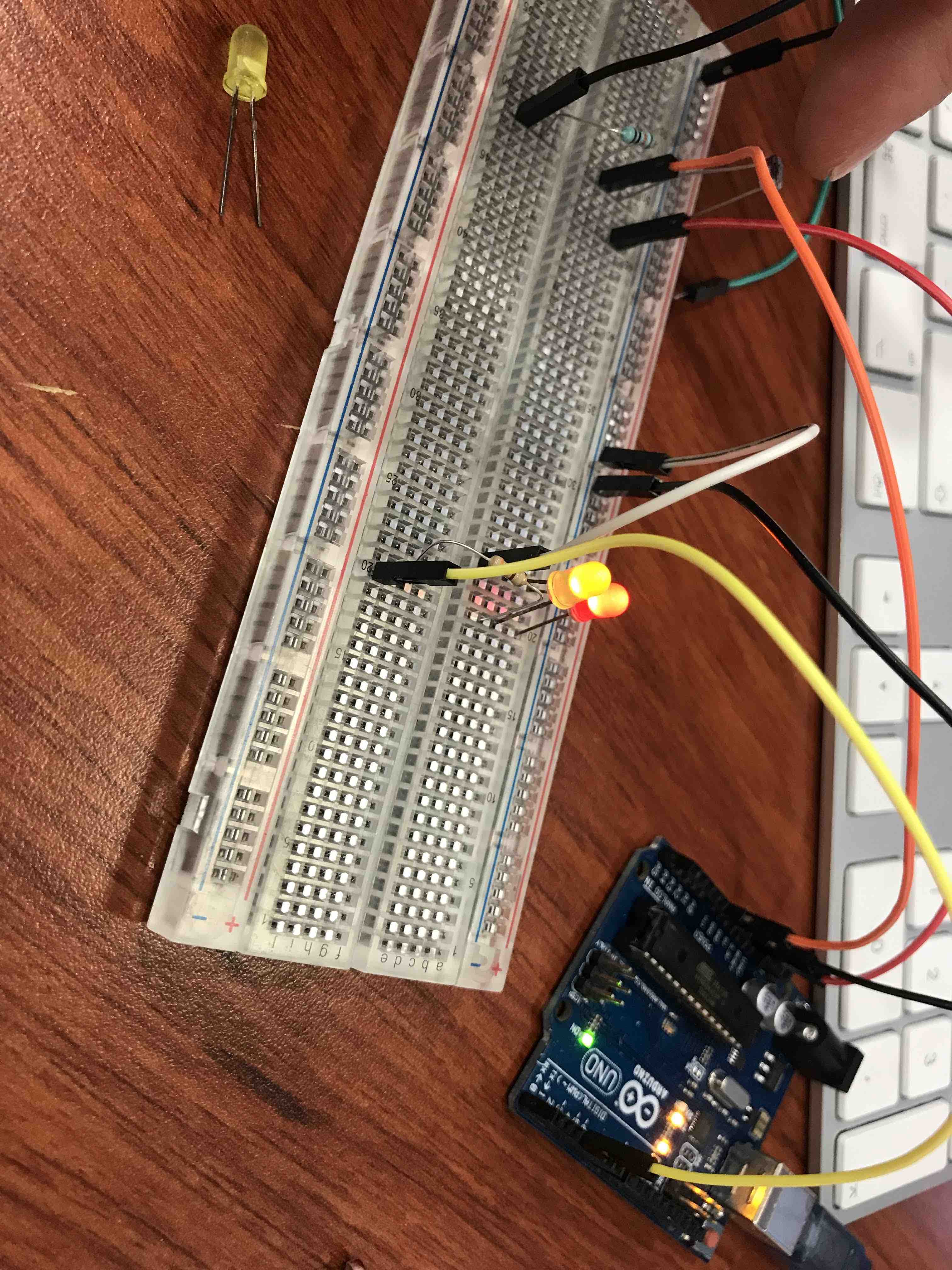
Here I´m testing leds
ON/OFF with an LDR

Then I redesign the
SAMDINO to fit my requeriments so I can replace the arduino with
it and start programming a new code
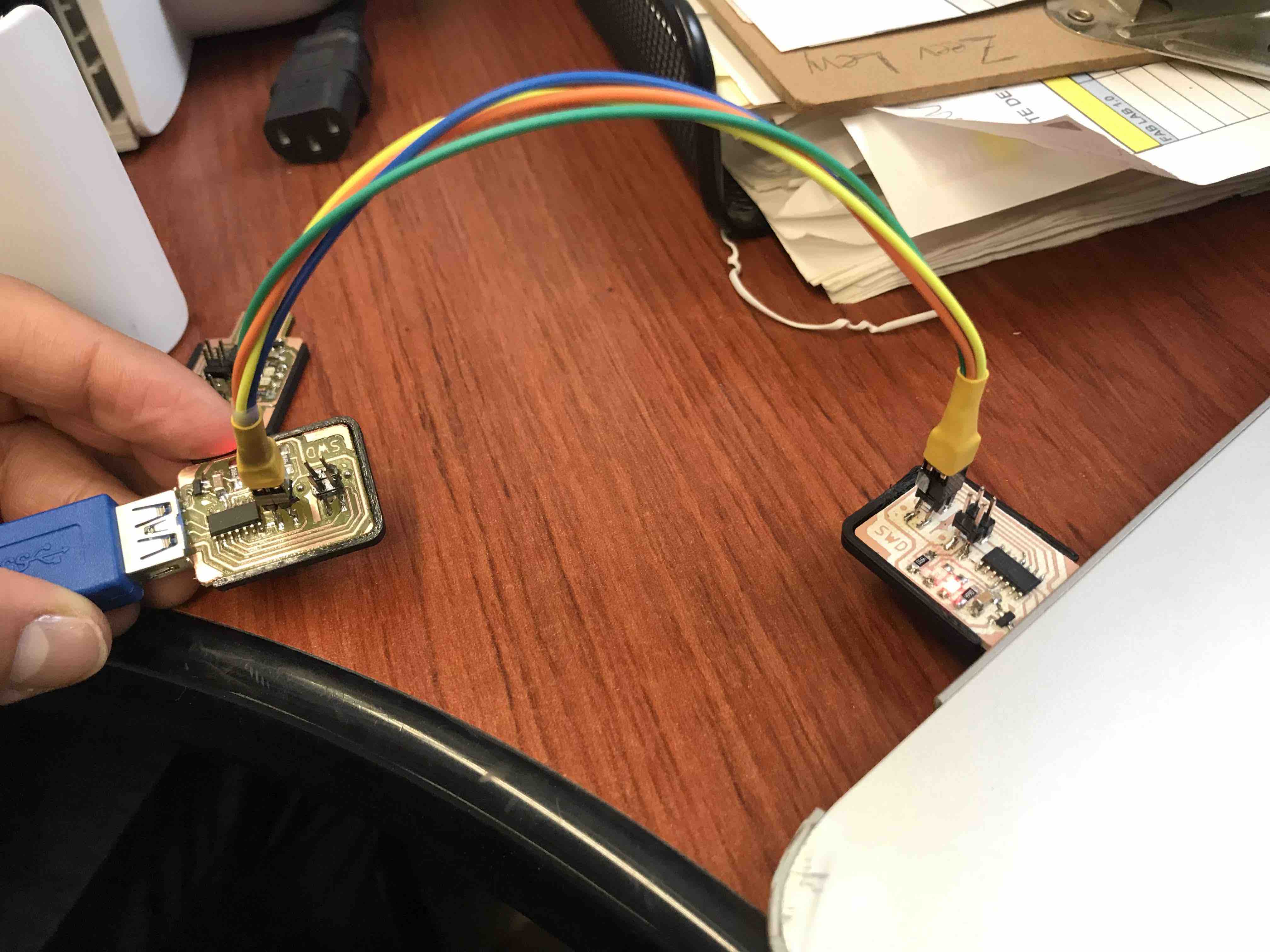
First I had to
connect my SWD to "life" so I can program my PCB Hugodino with
this
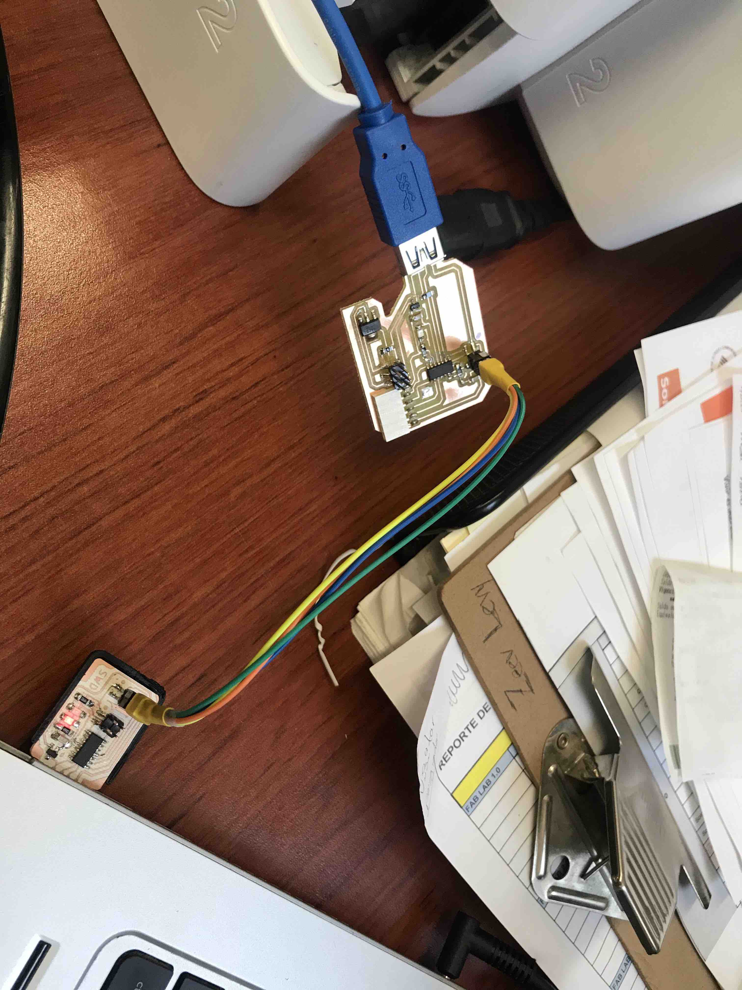
Here are the hugodino
board and the SWD, the connection was ok
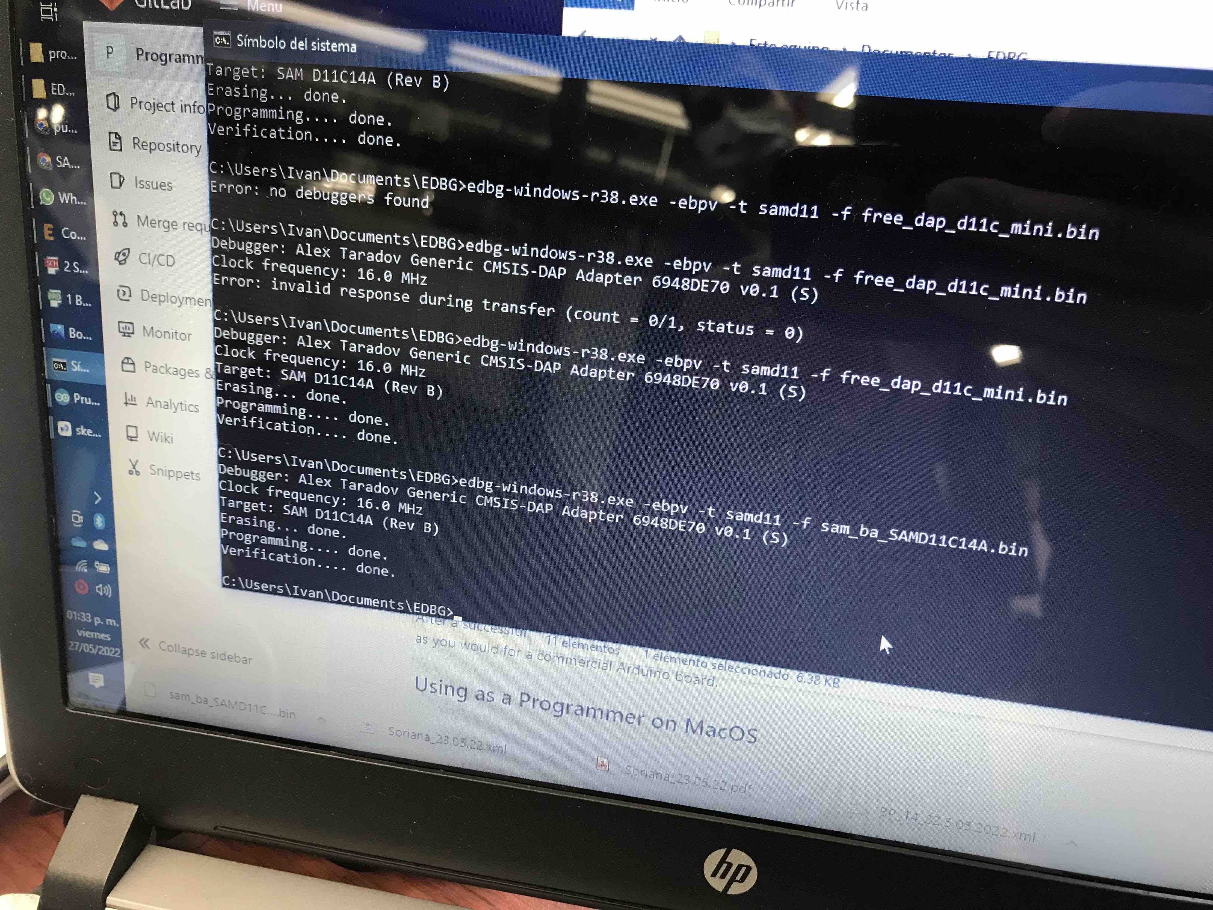
Everything goes well.
Here we use the EDBG to "turn on" the hugodino board using the WSD
PCB
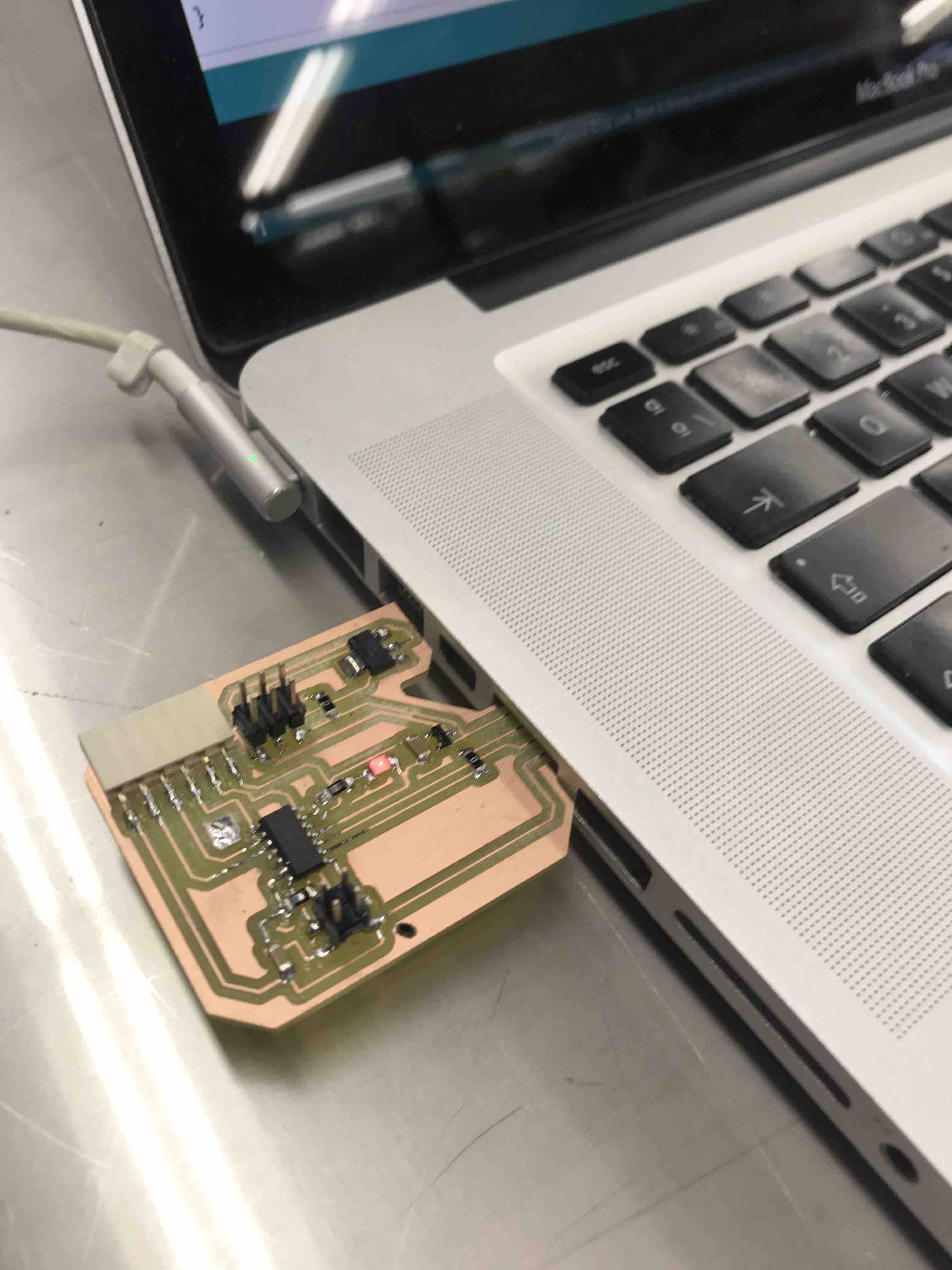
The led of my PCB is
on indicating we are good
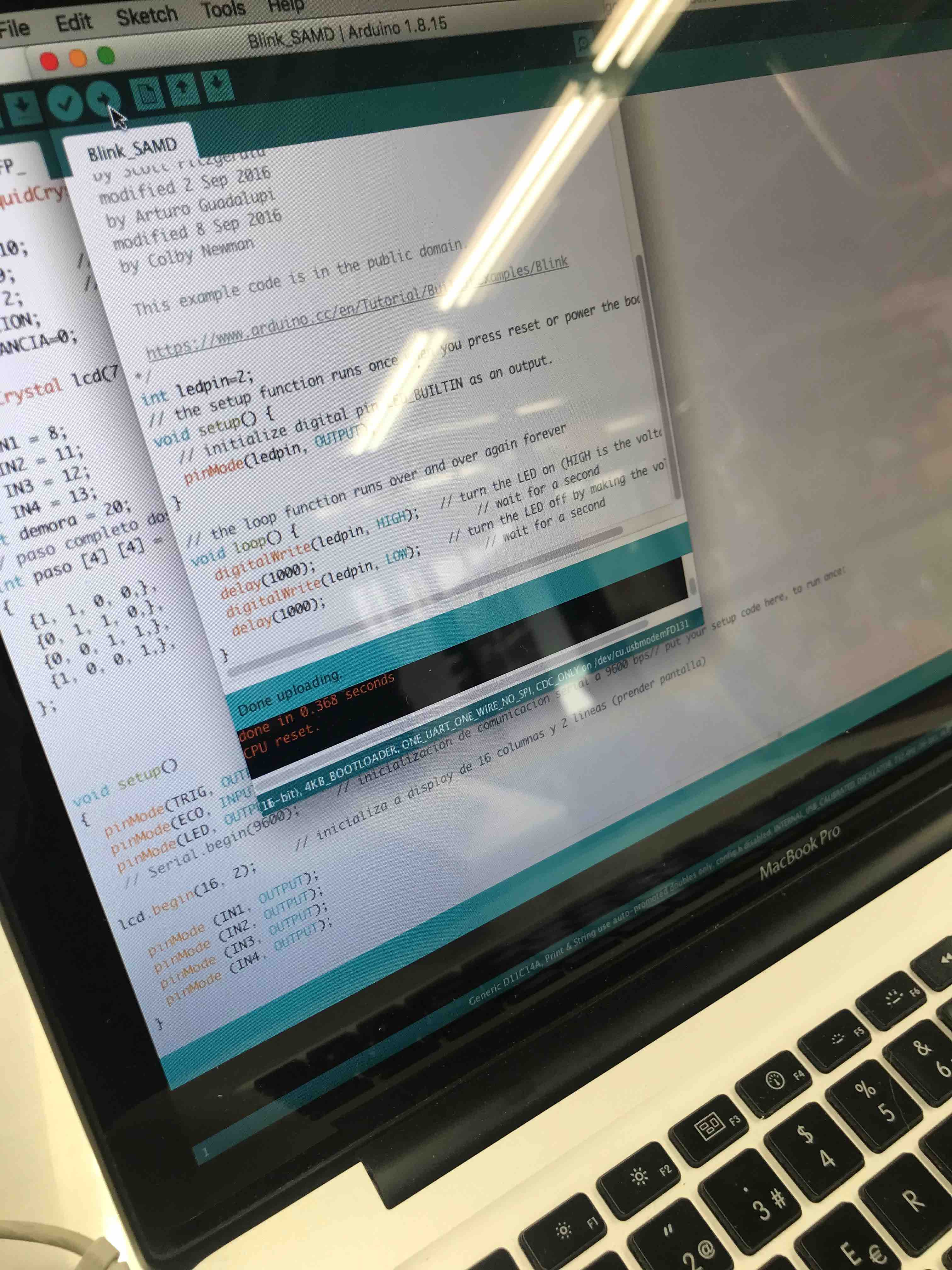
Mhere the code for
the SAMDINO that makes the LED blink, in the future I´m going to
use the SAMDINO code to design my own codes to fit my requirements
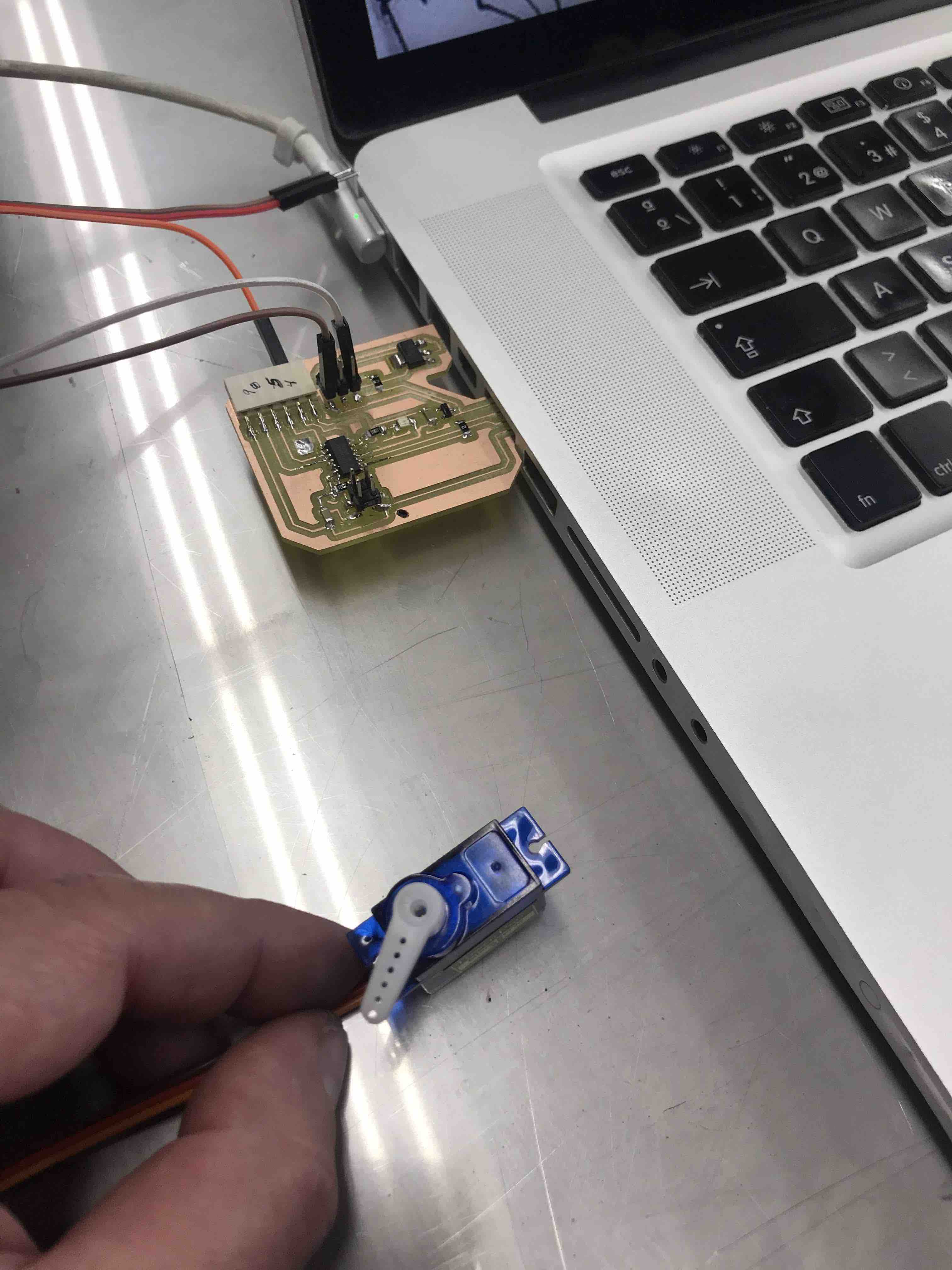
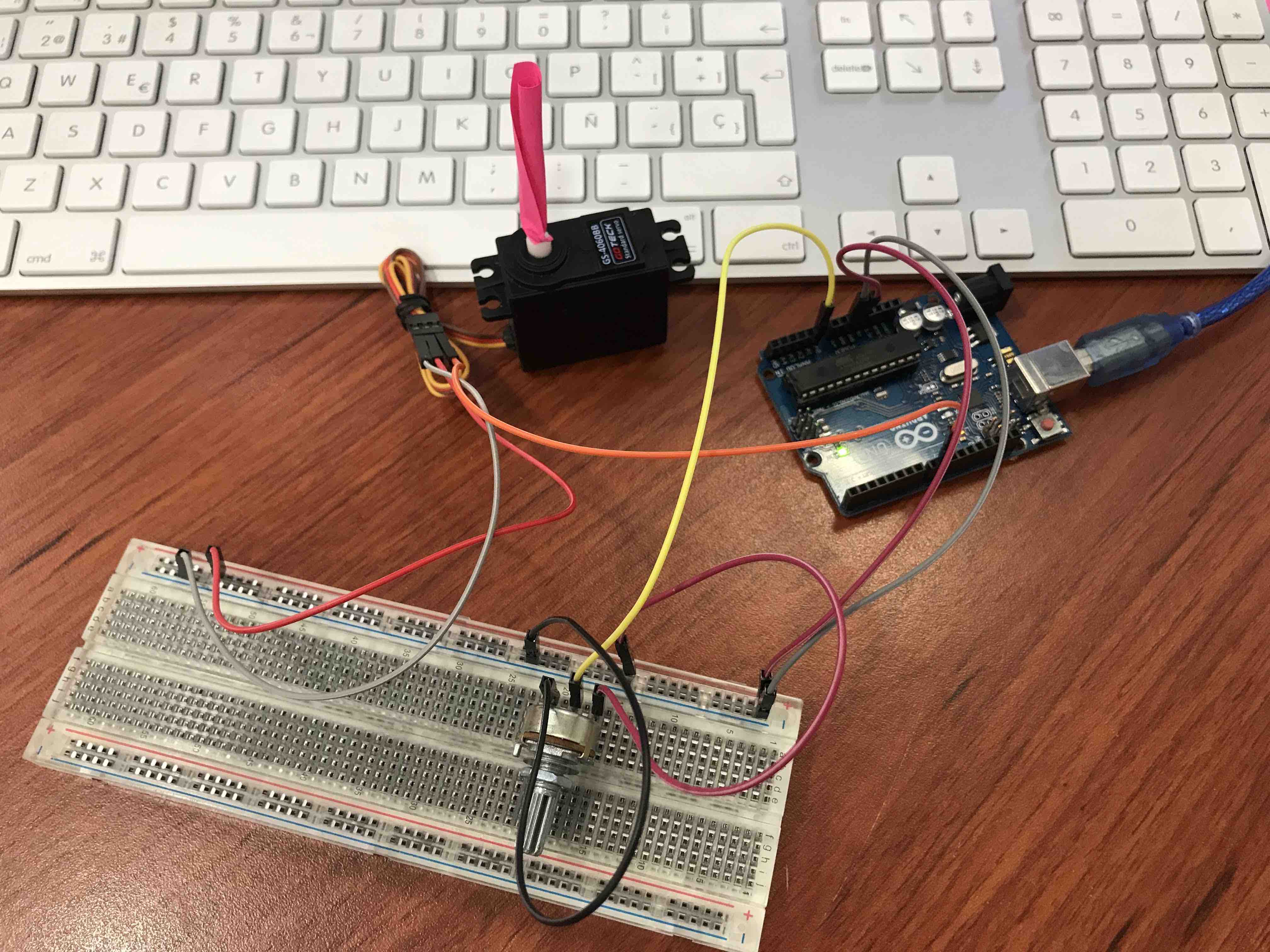
The servo is moving,
thats really fine
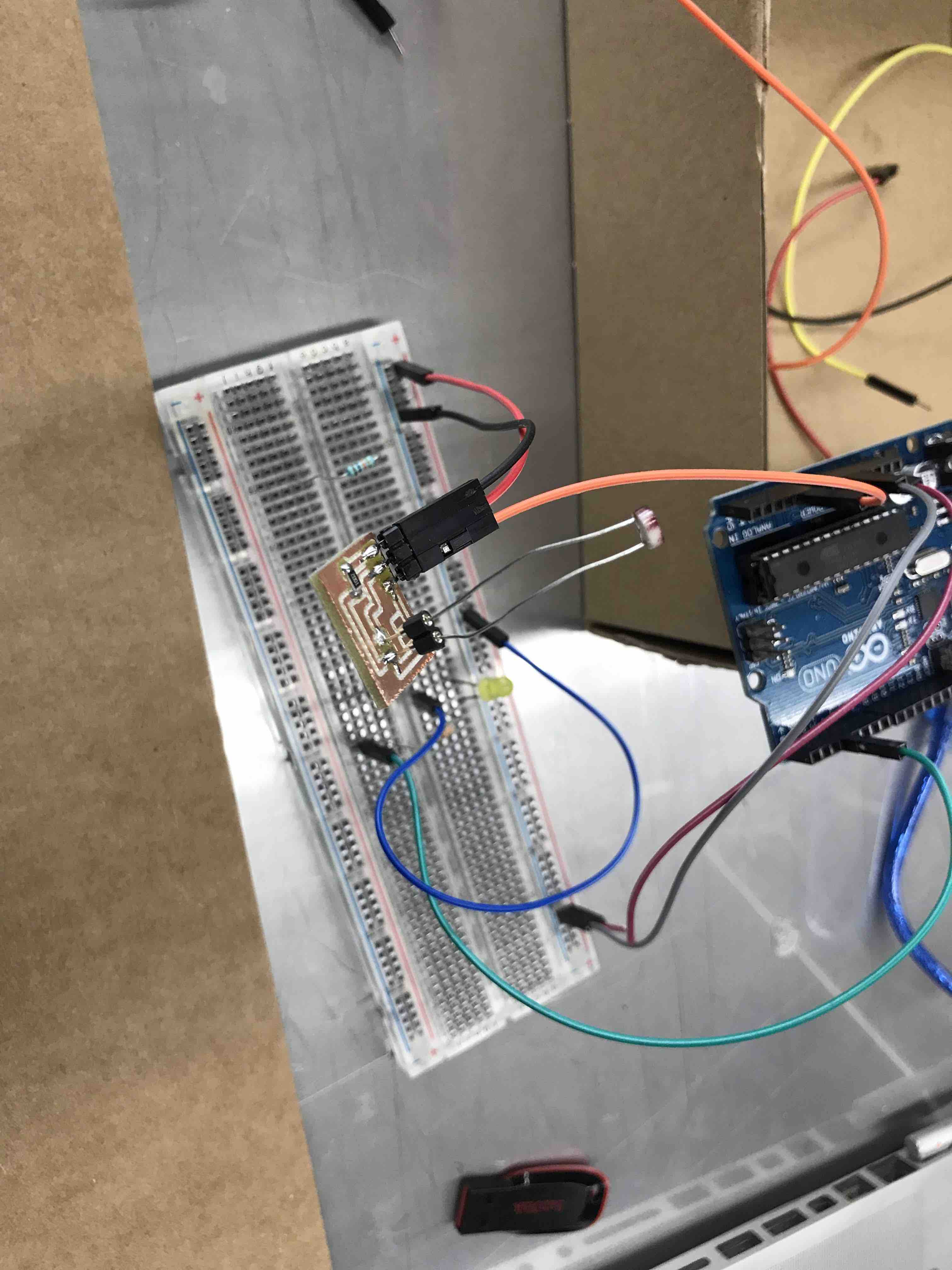
Testing the LDR PCB
with a breadboard to see it it works before use it directly with
my board.
an image of the first
2 PCBs I did for my project
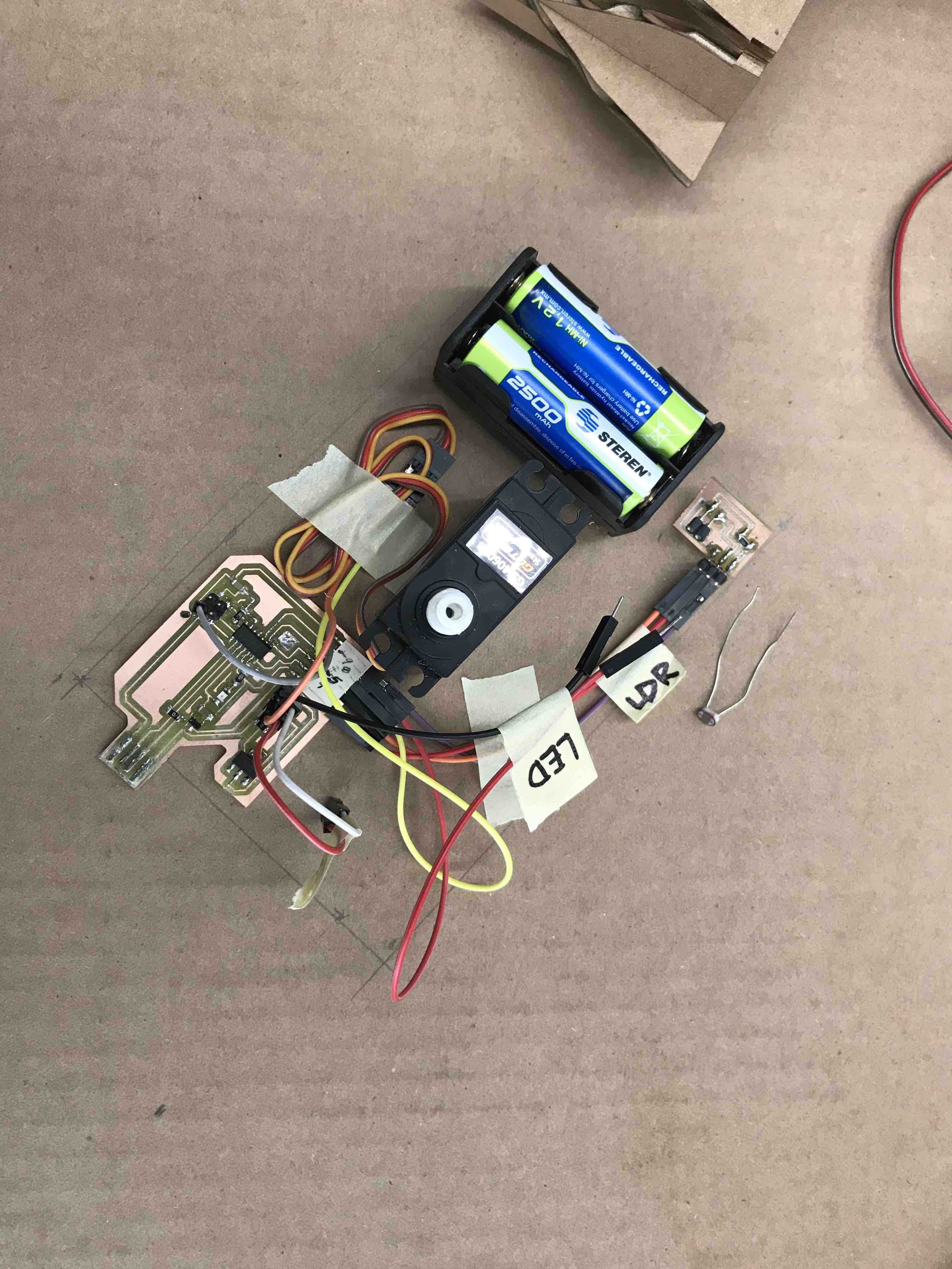
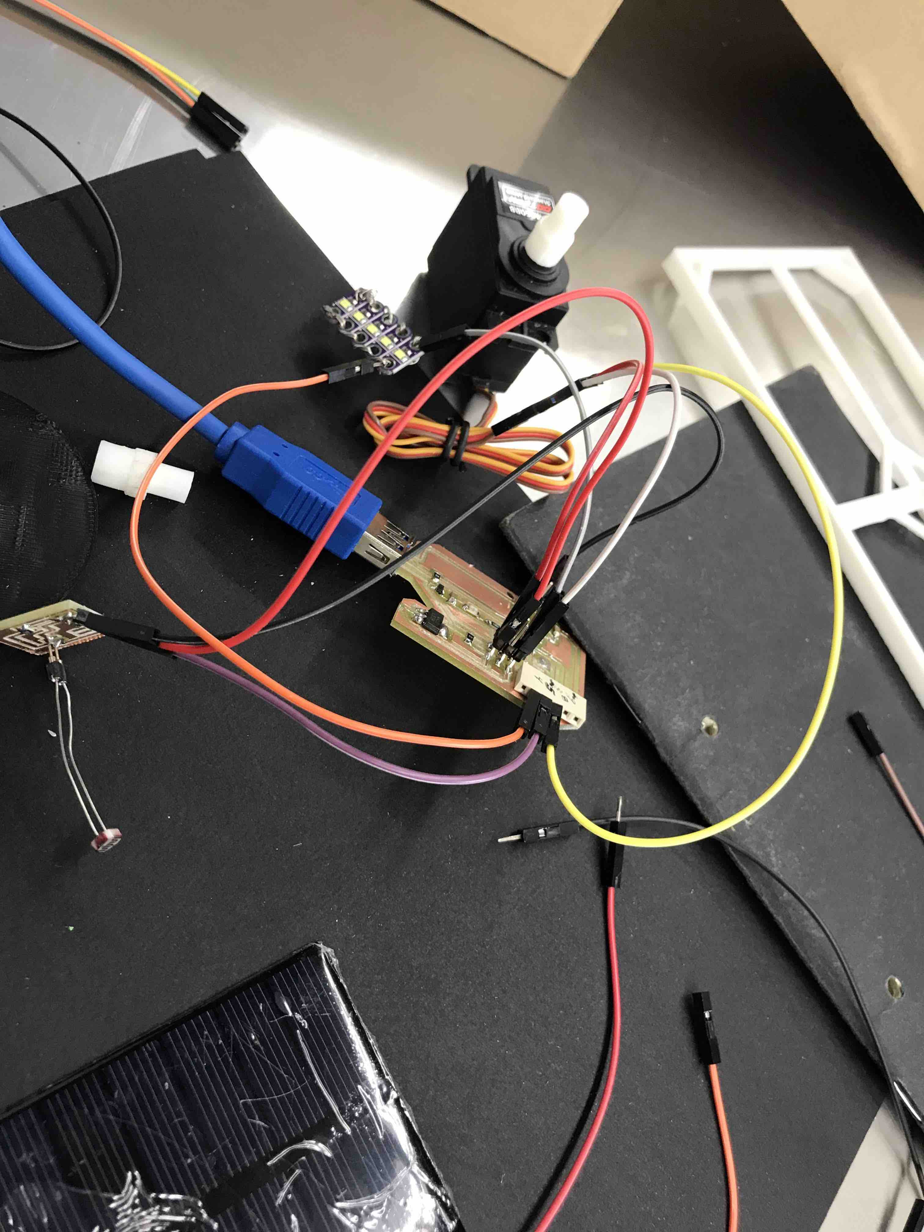
I put some masking
tape to identify wich cable is for what component-connection
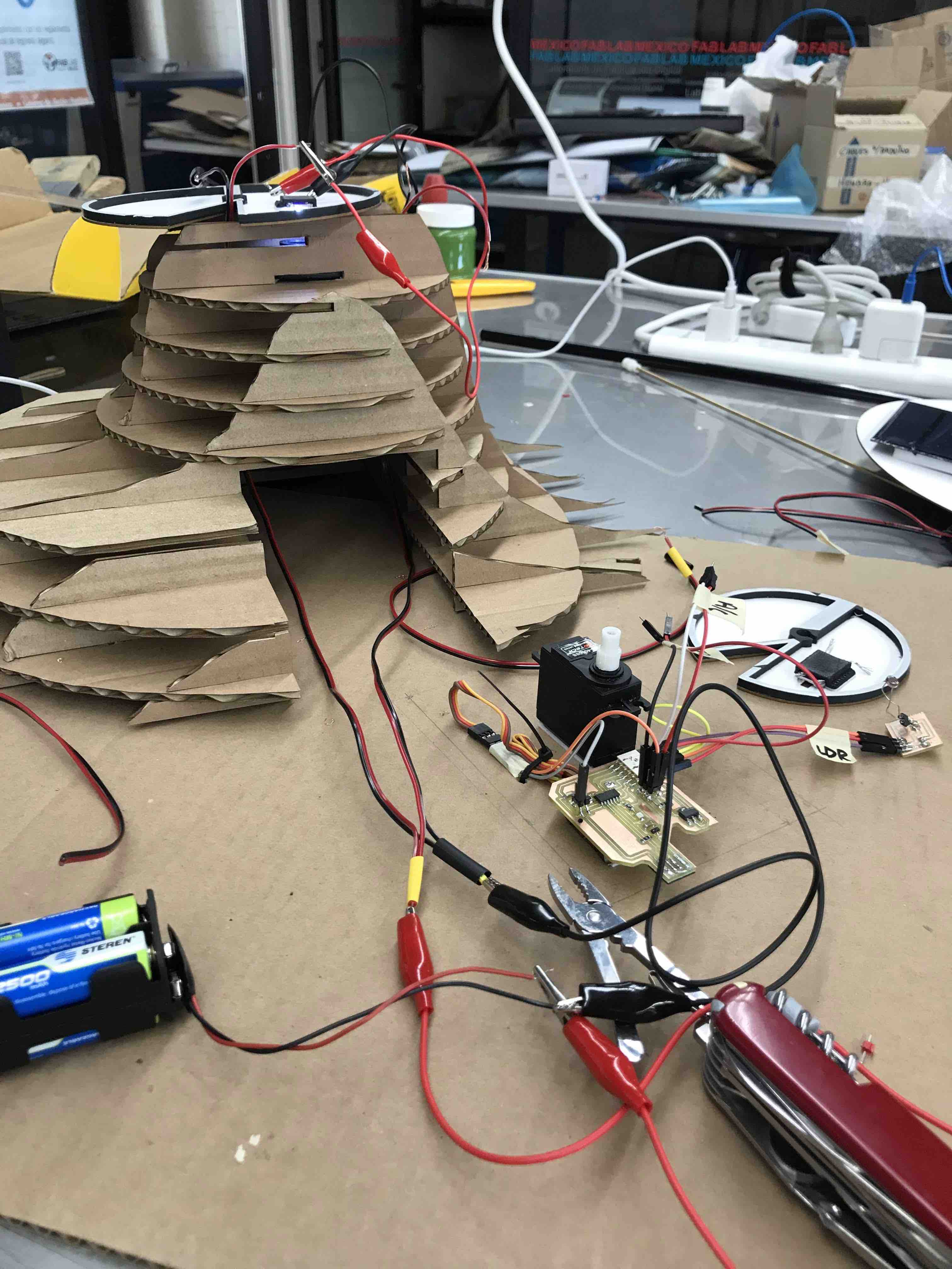
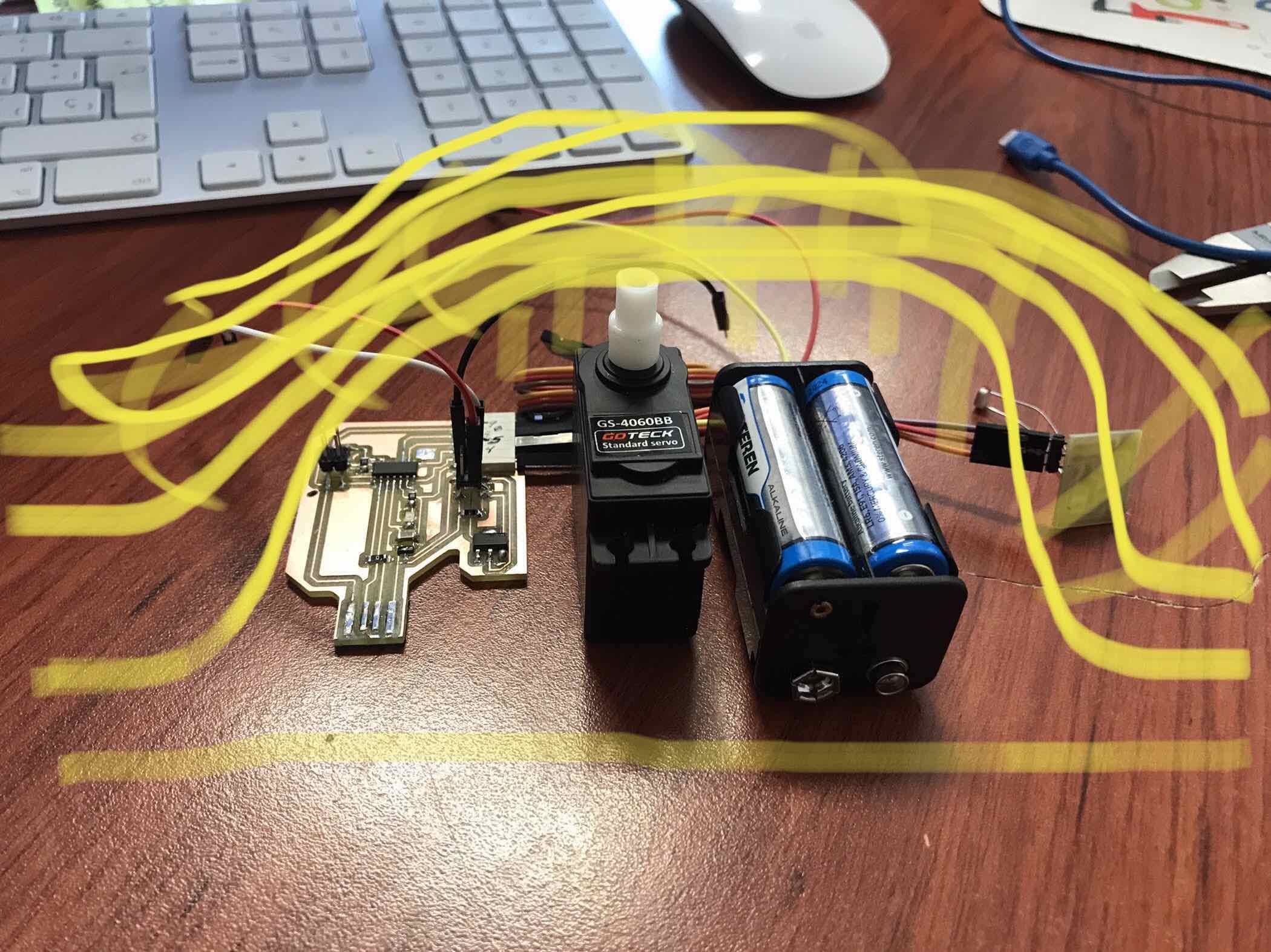
Remember the space i
need to be done in the base in the design phase? here it is, and
the servo, batteries, PCB etc will fit inside the base.
ASSEMBLe
a place to re-connect
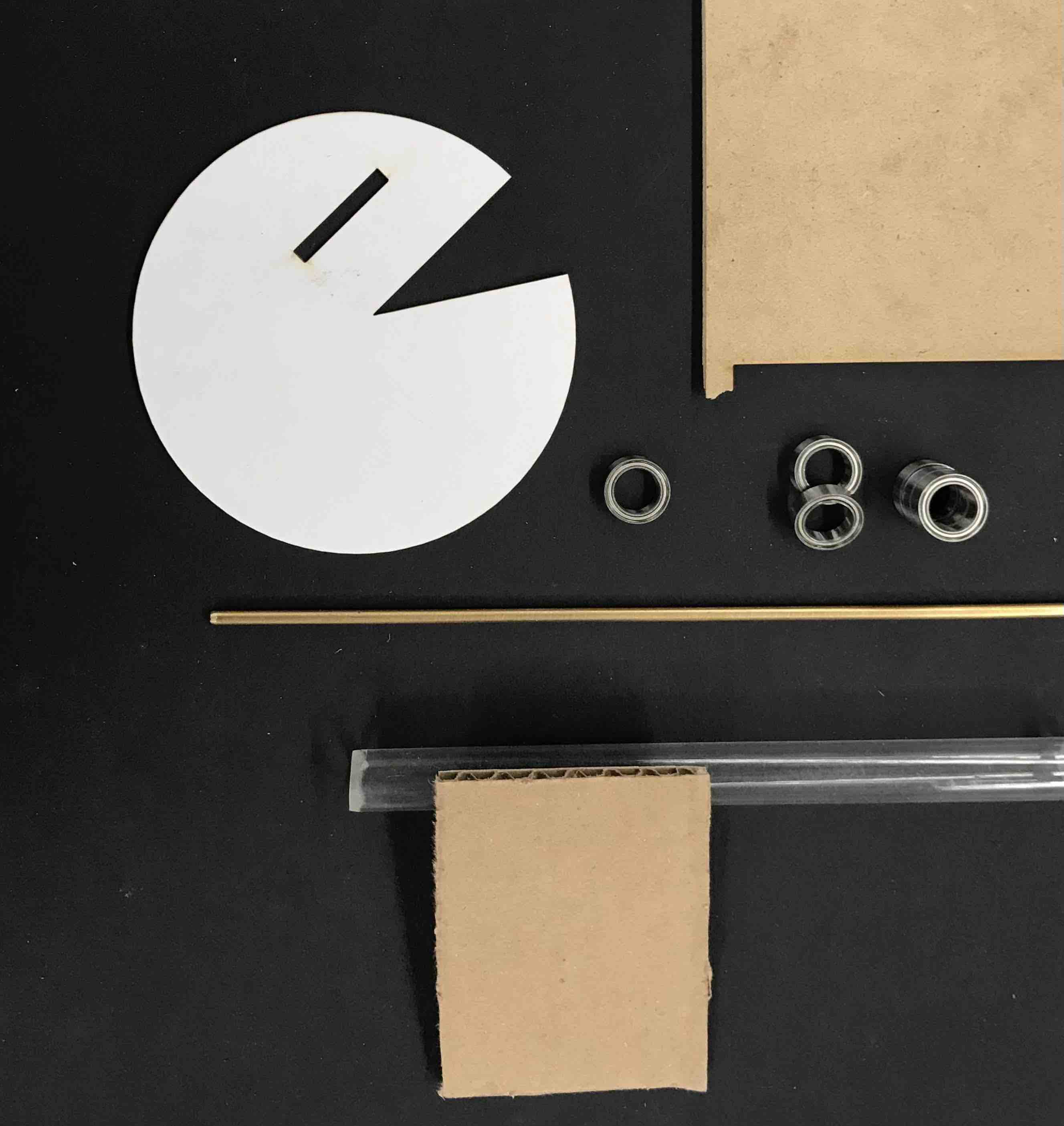
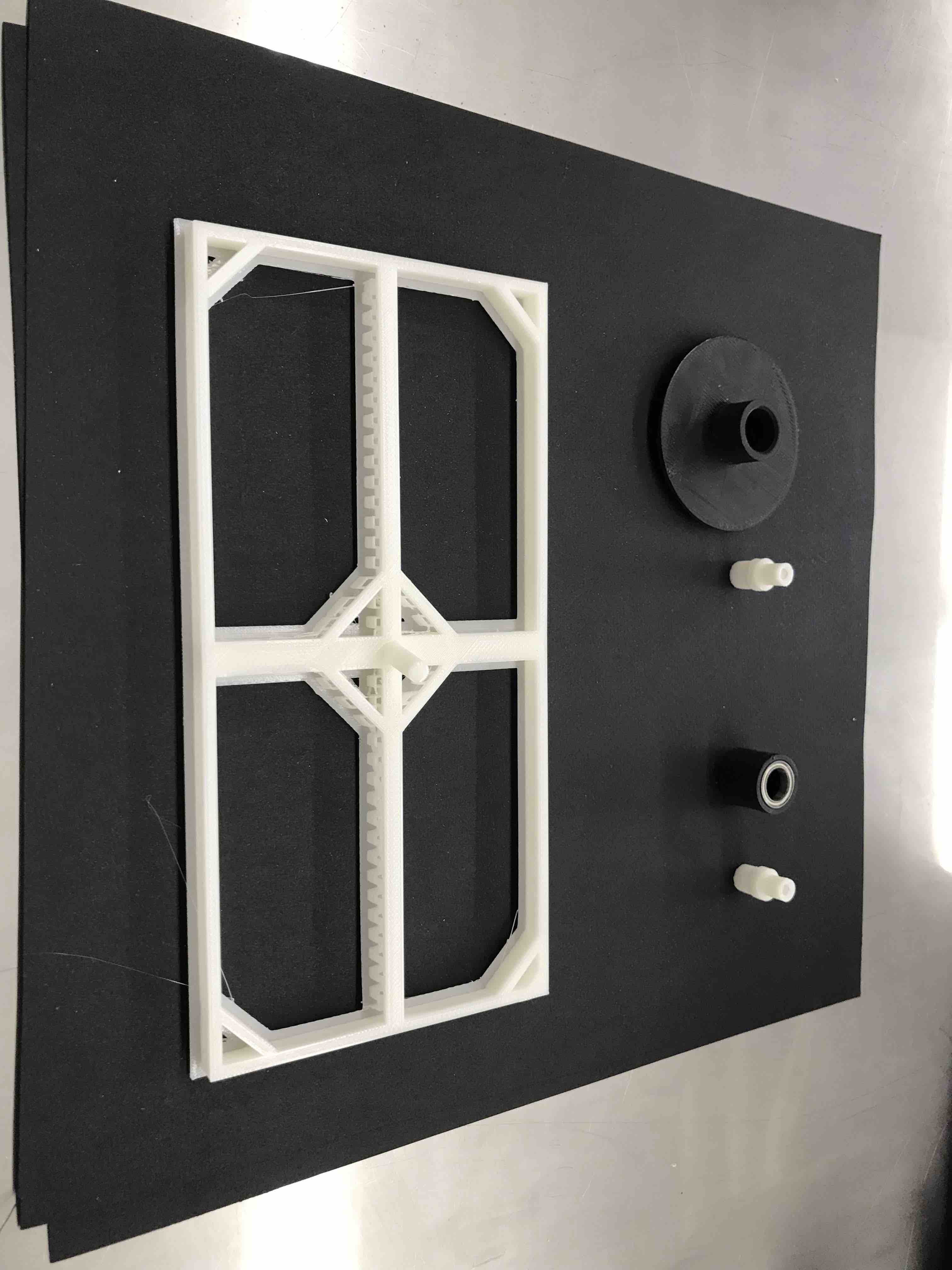
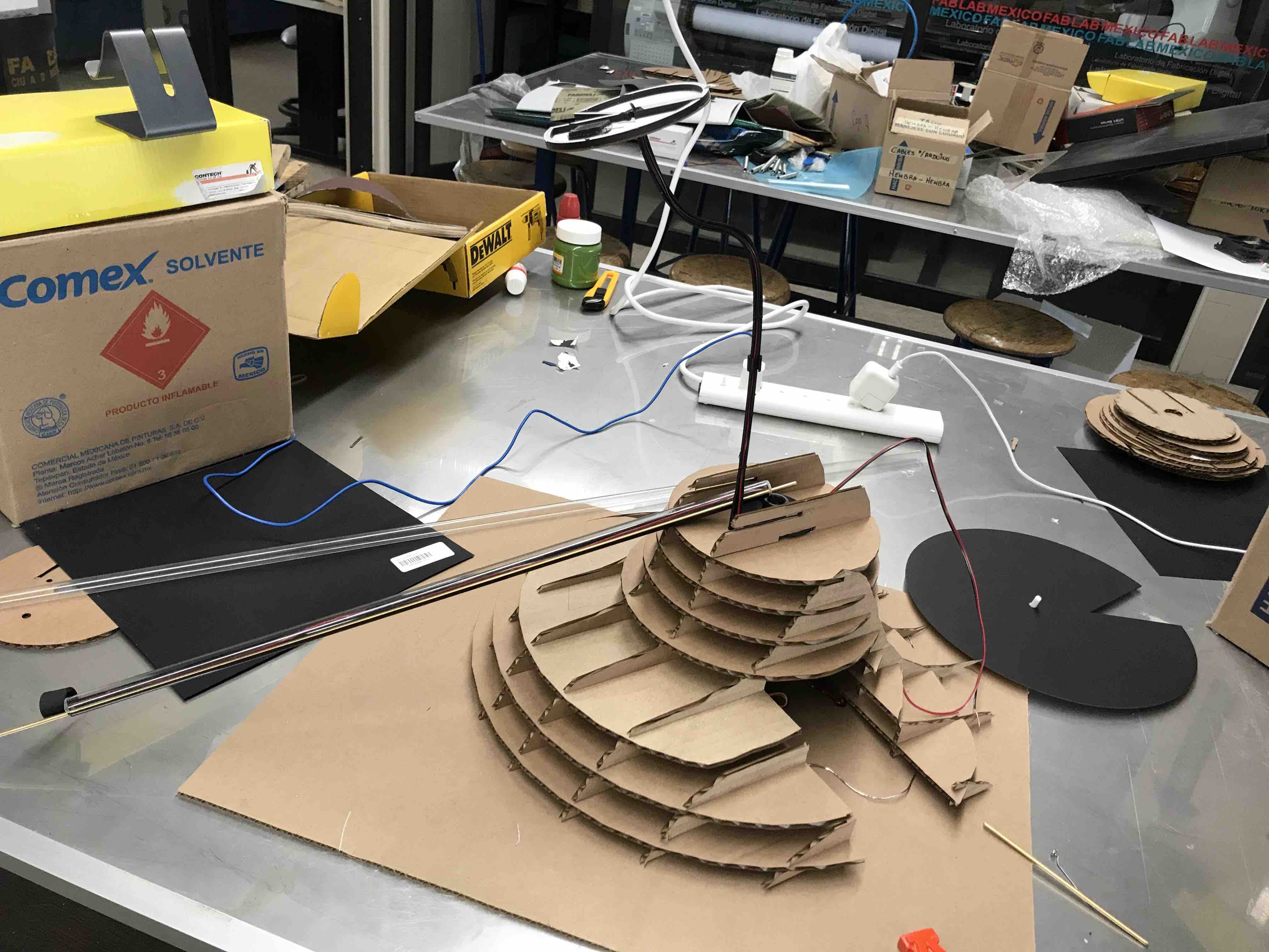
different materials to
be used in the prototype: corrugated cardboard, bearings, acrylic
pipe, cardboard and a brass rod.
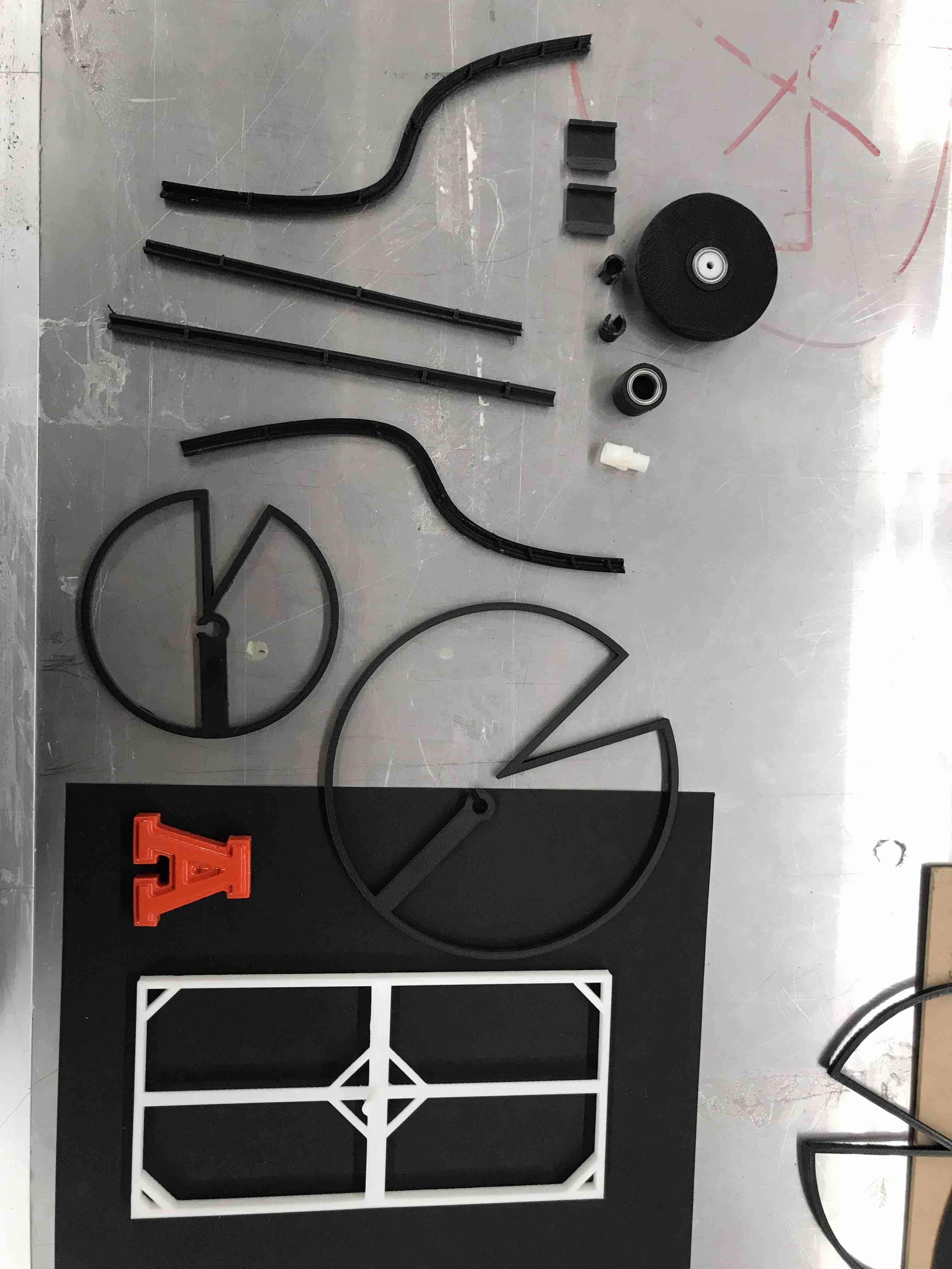
3D printed components
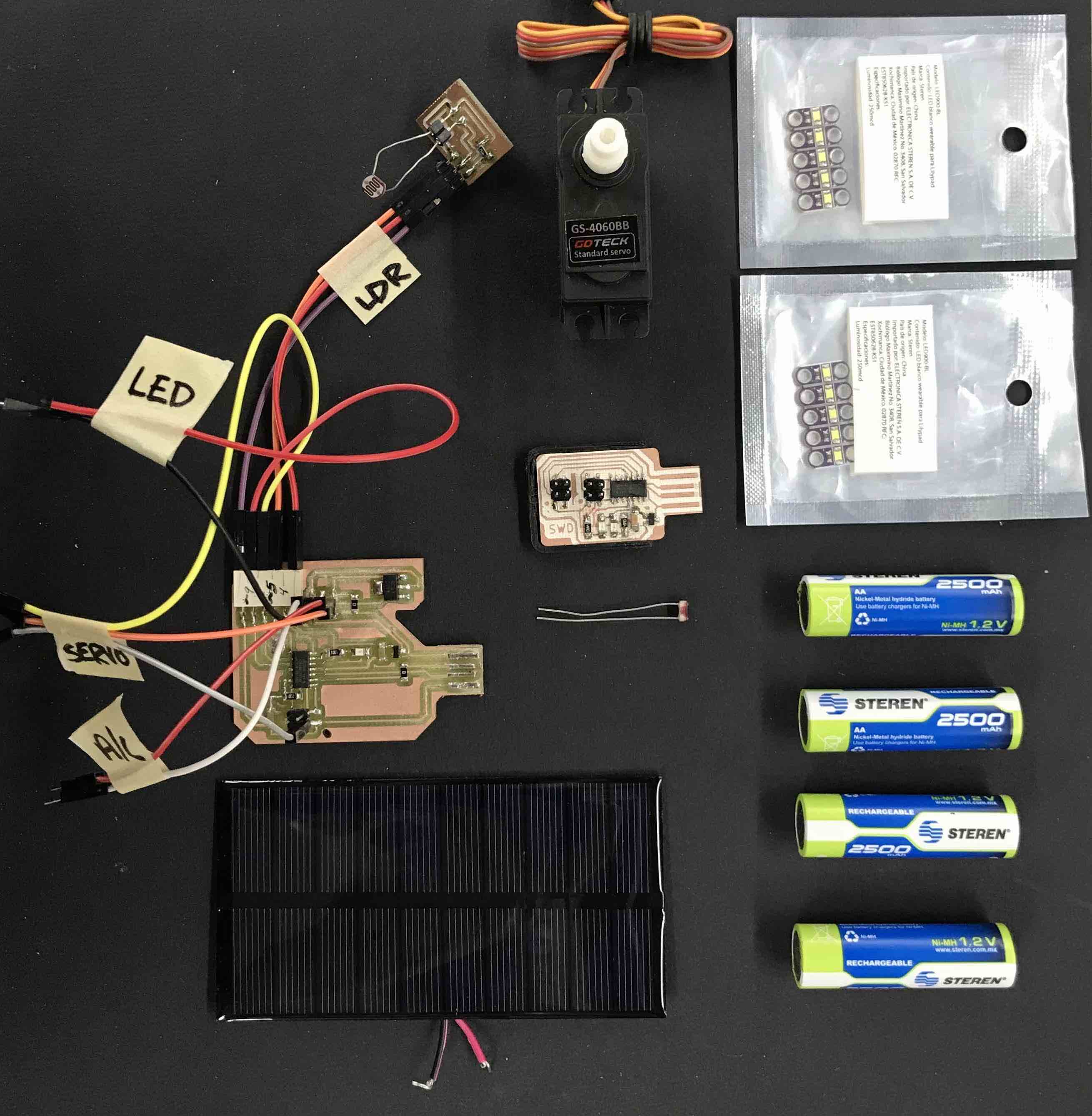
Electronics components
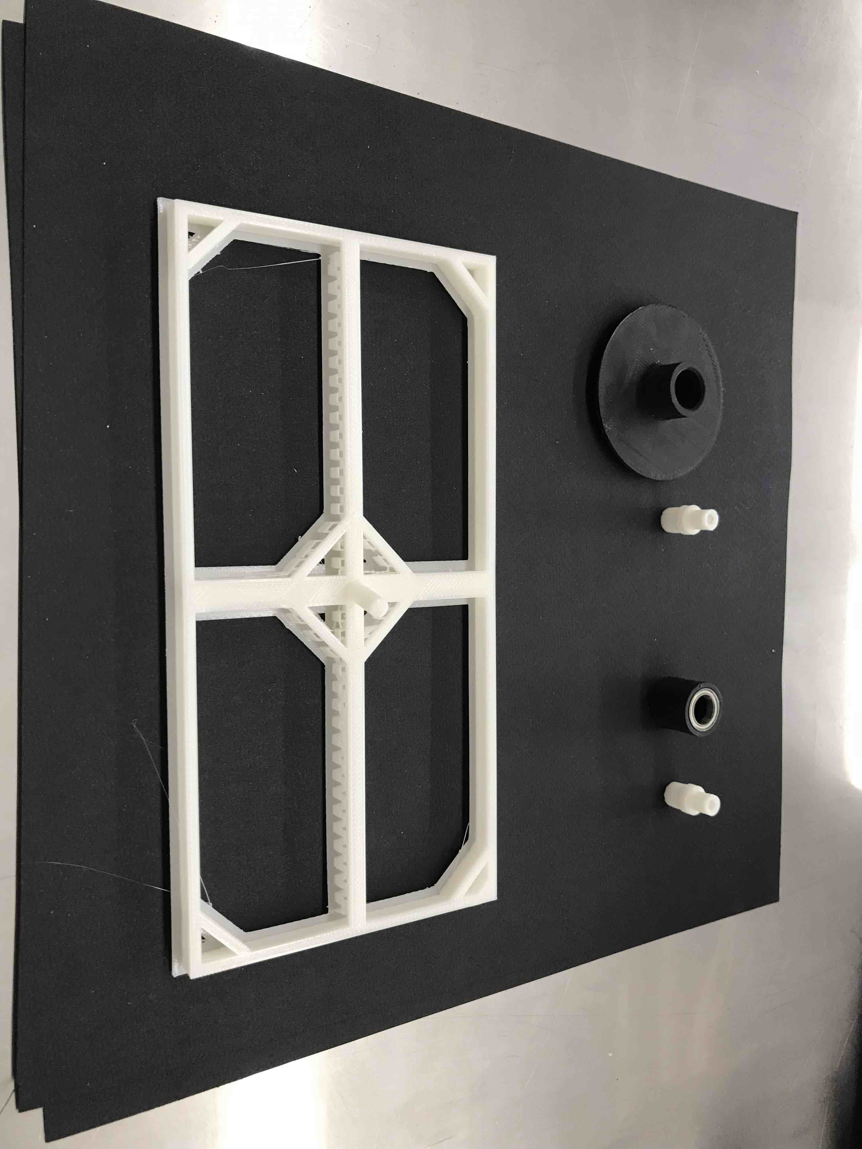
some 3d printed
objects; solar cell support, axis of rotation.
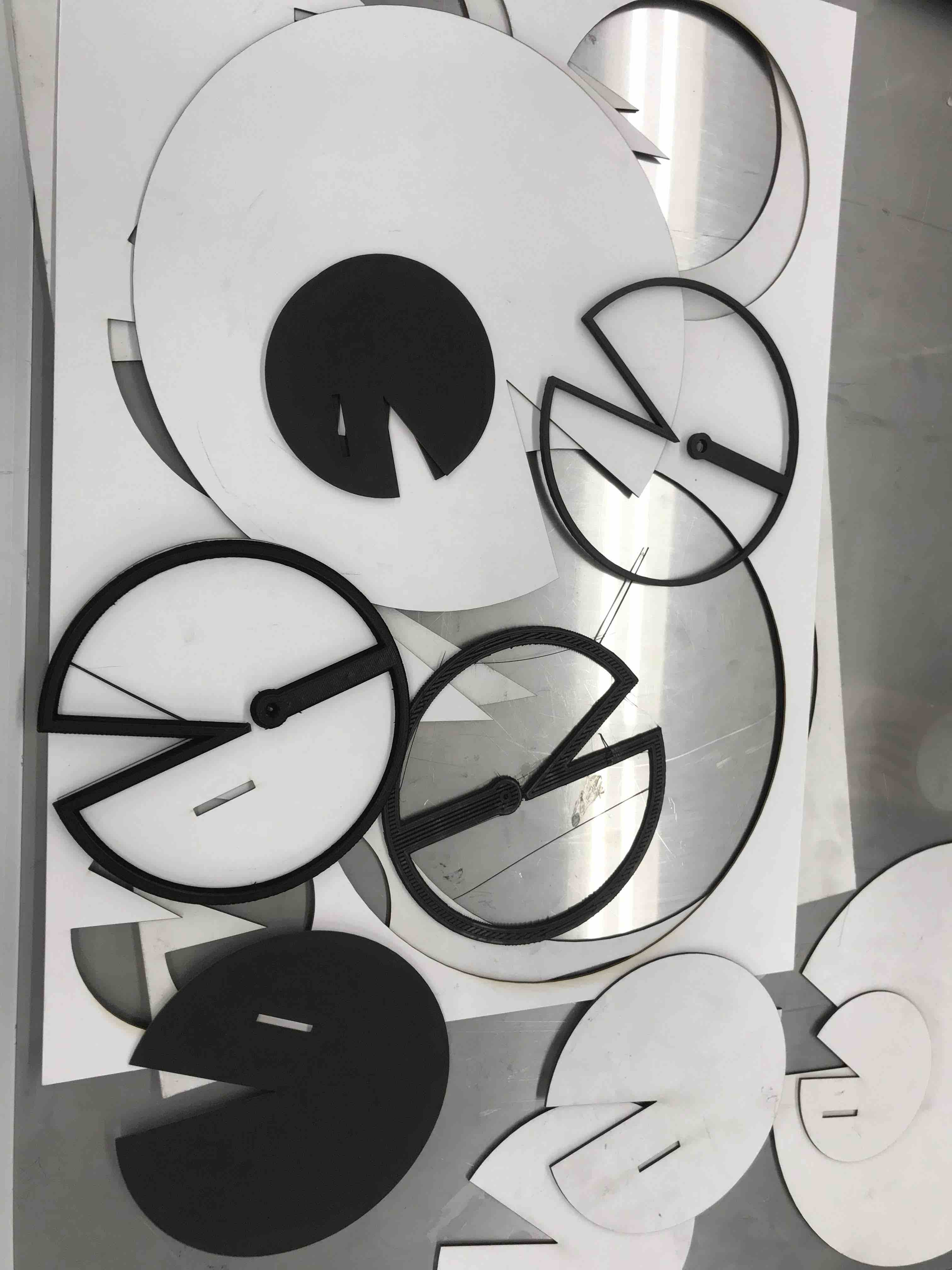
Cardboard and 3d
printed pieces that will form the leafs
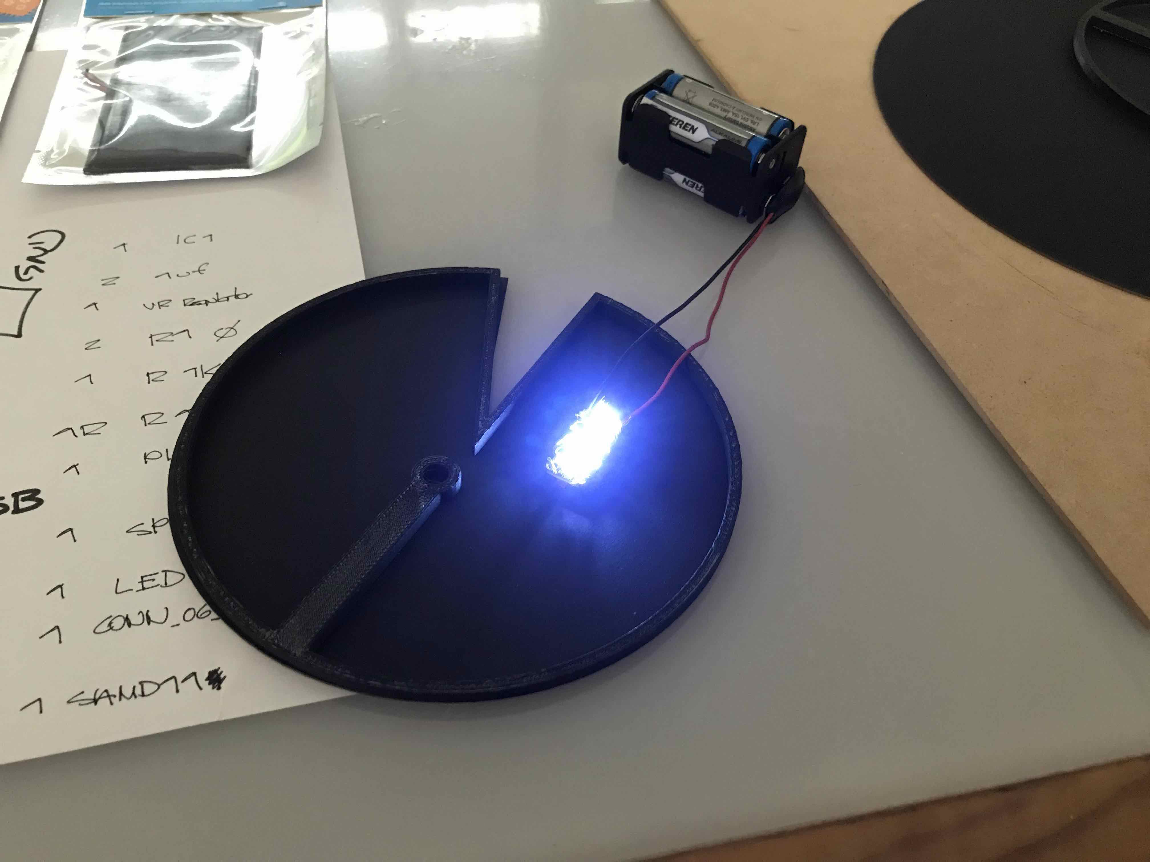
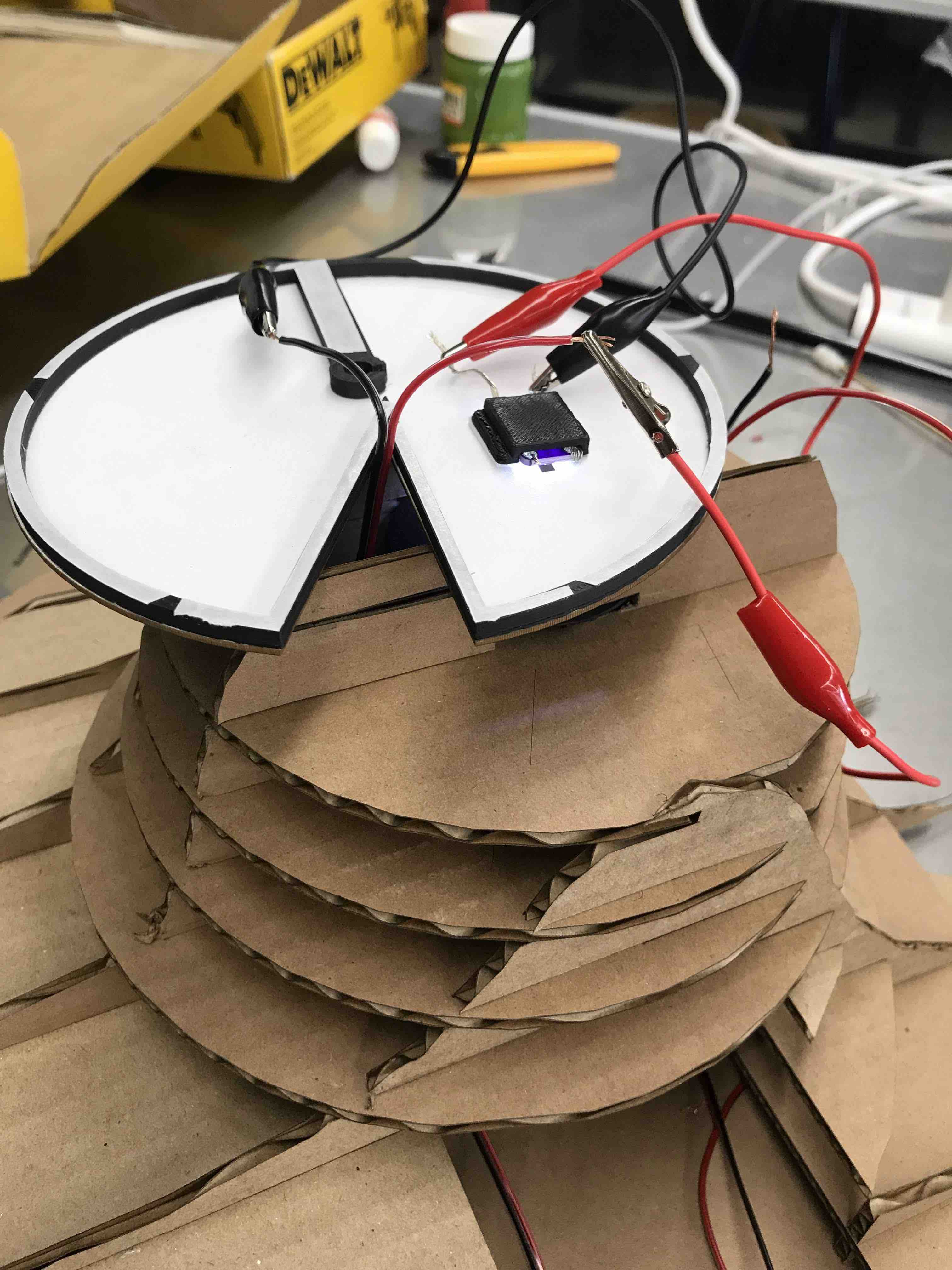
testing LEDs in the
leaf
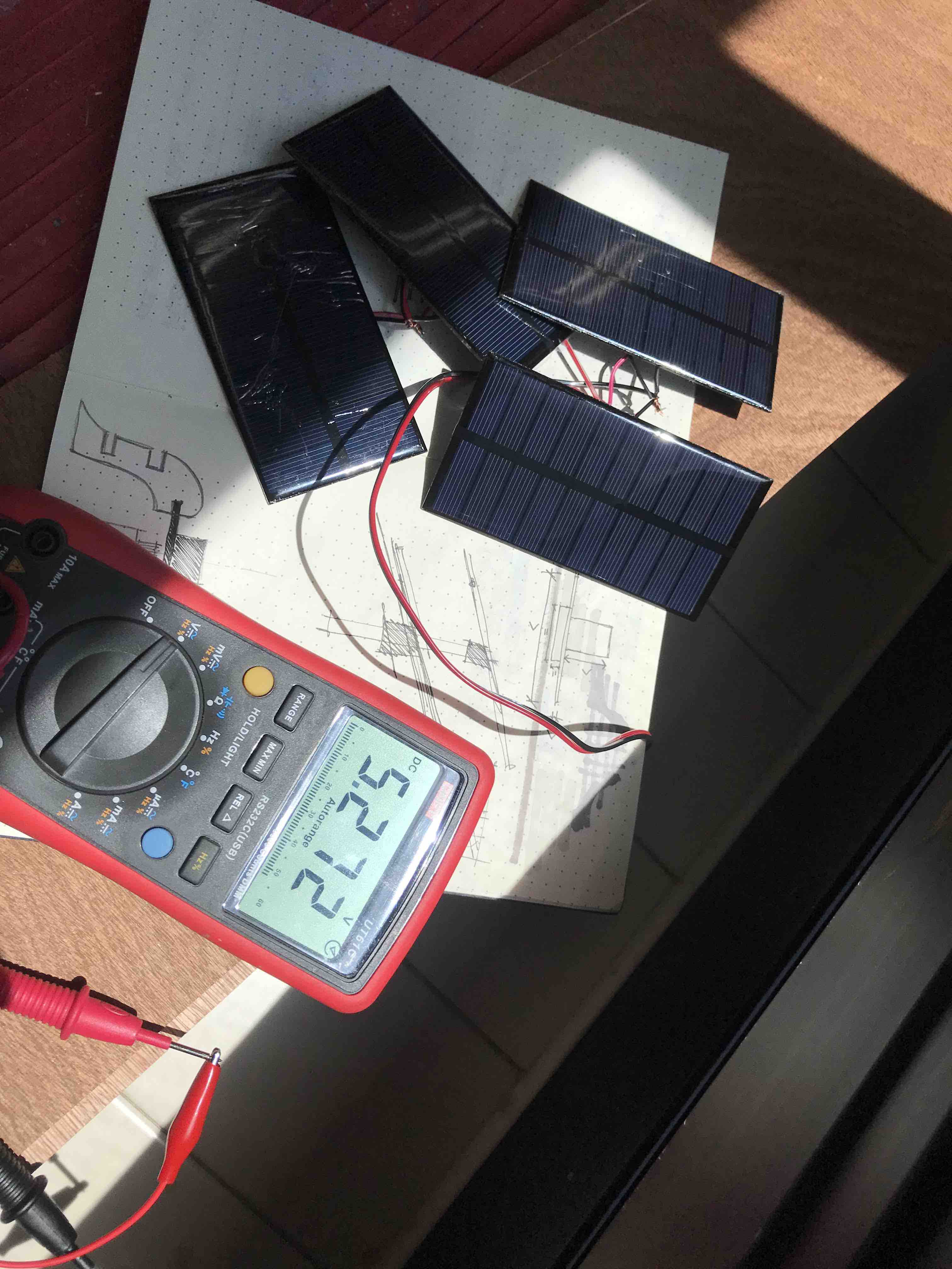
Checking the voltage,
then I charge the rechargeable batteries with the solar cells, I
made an exercise of half an hour and the batteries went from 5.0 to
5.286
The PCBs, servo almost
done and the base has all the upper components fit
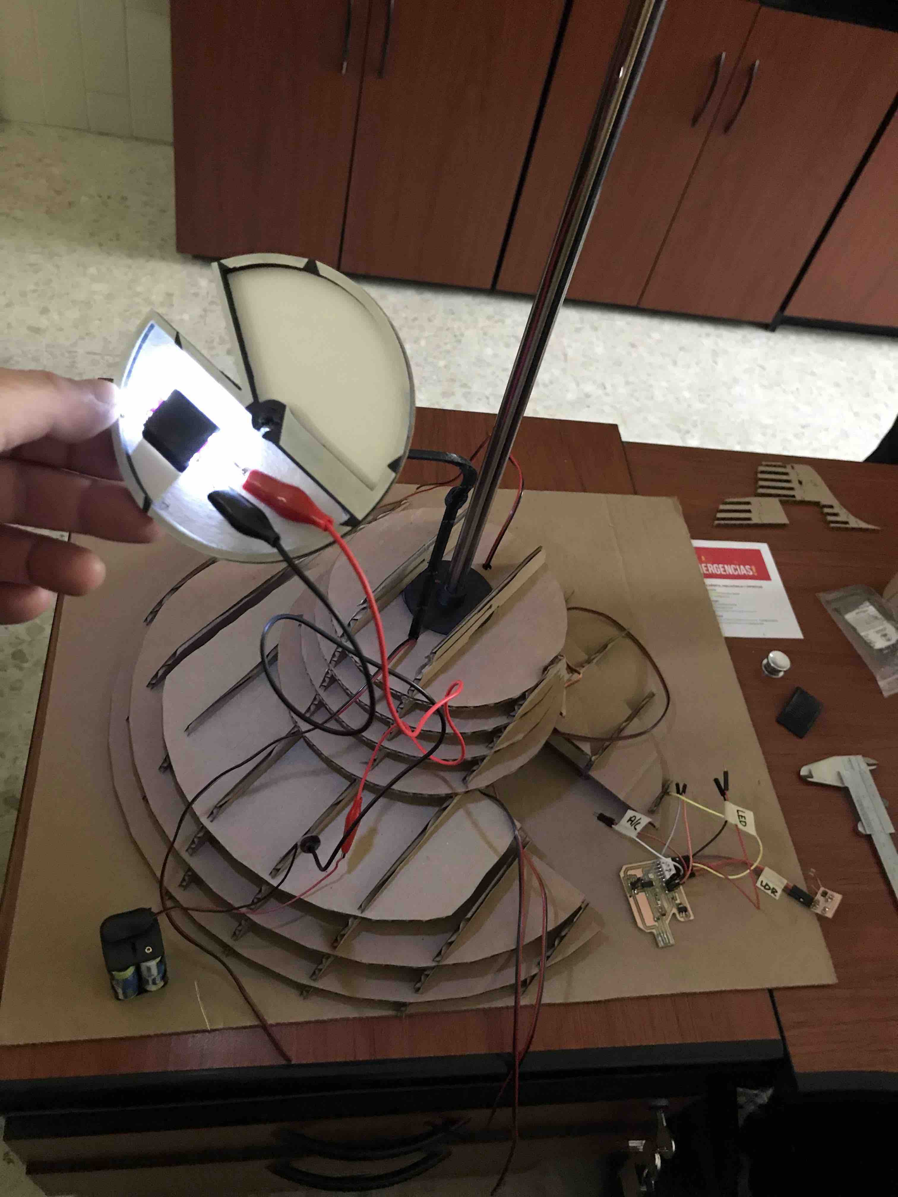
connecting the LEDS in
their place and checking electrical connections
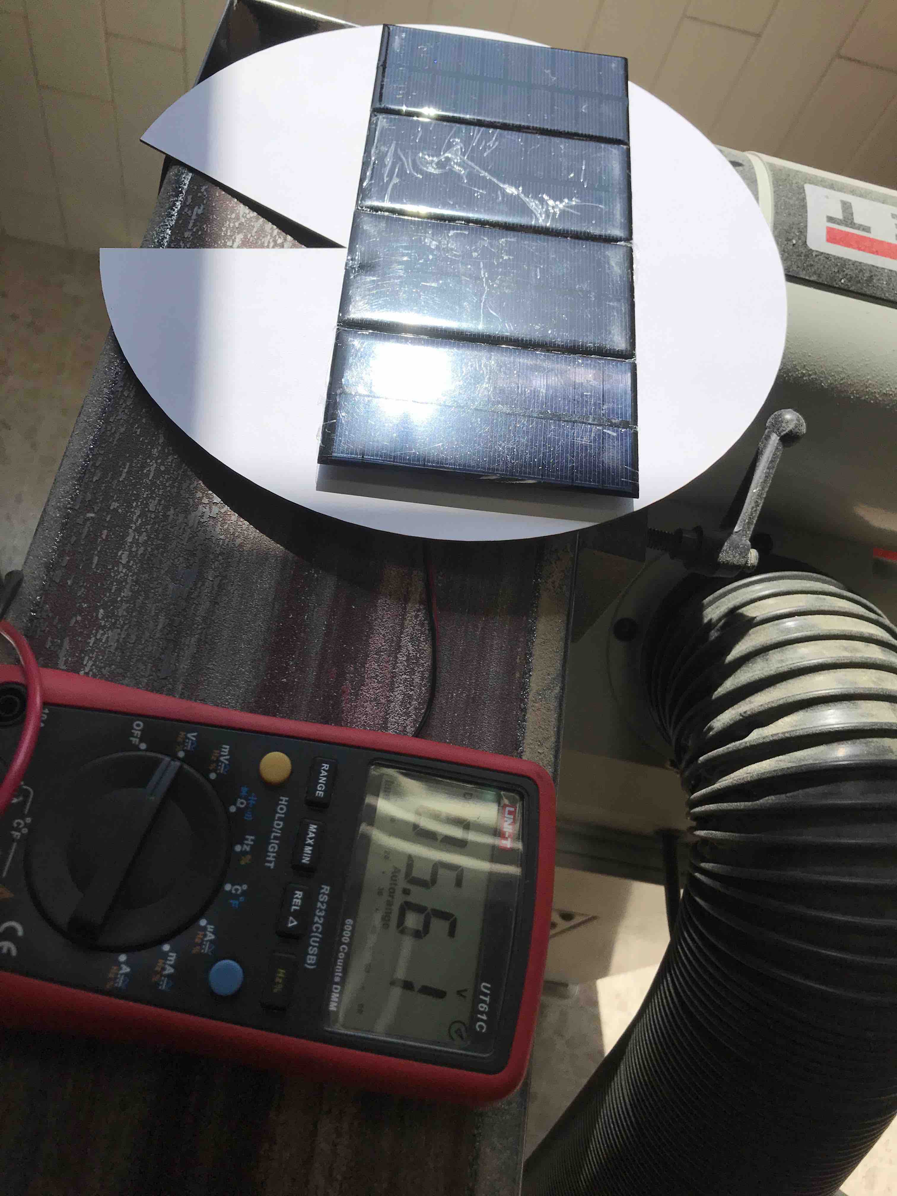
Checking the Voltage of
the solar panels
fitting the secondary
leafs supports that guide the cables from the base to the LEDs
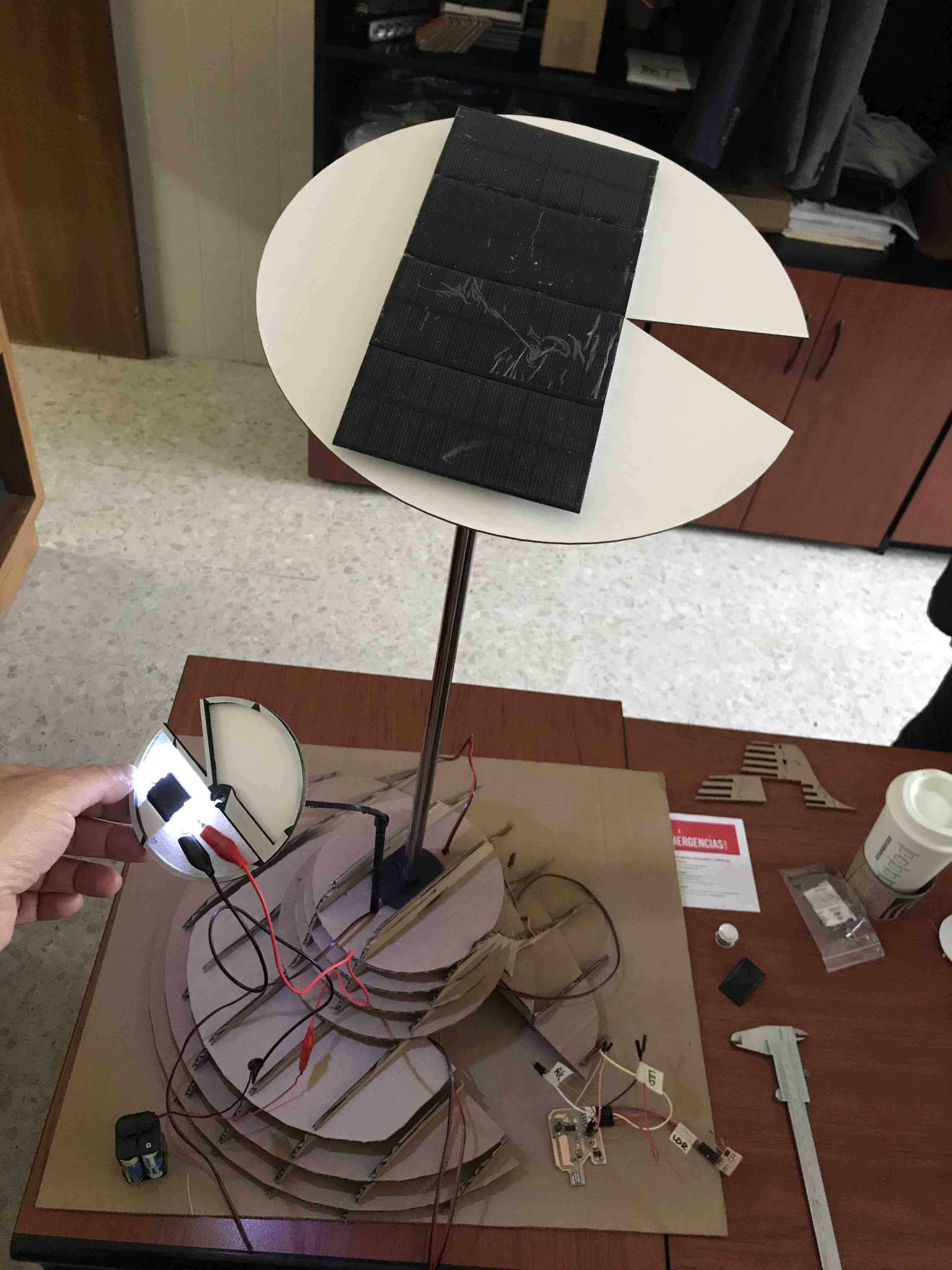
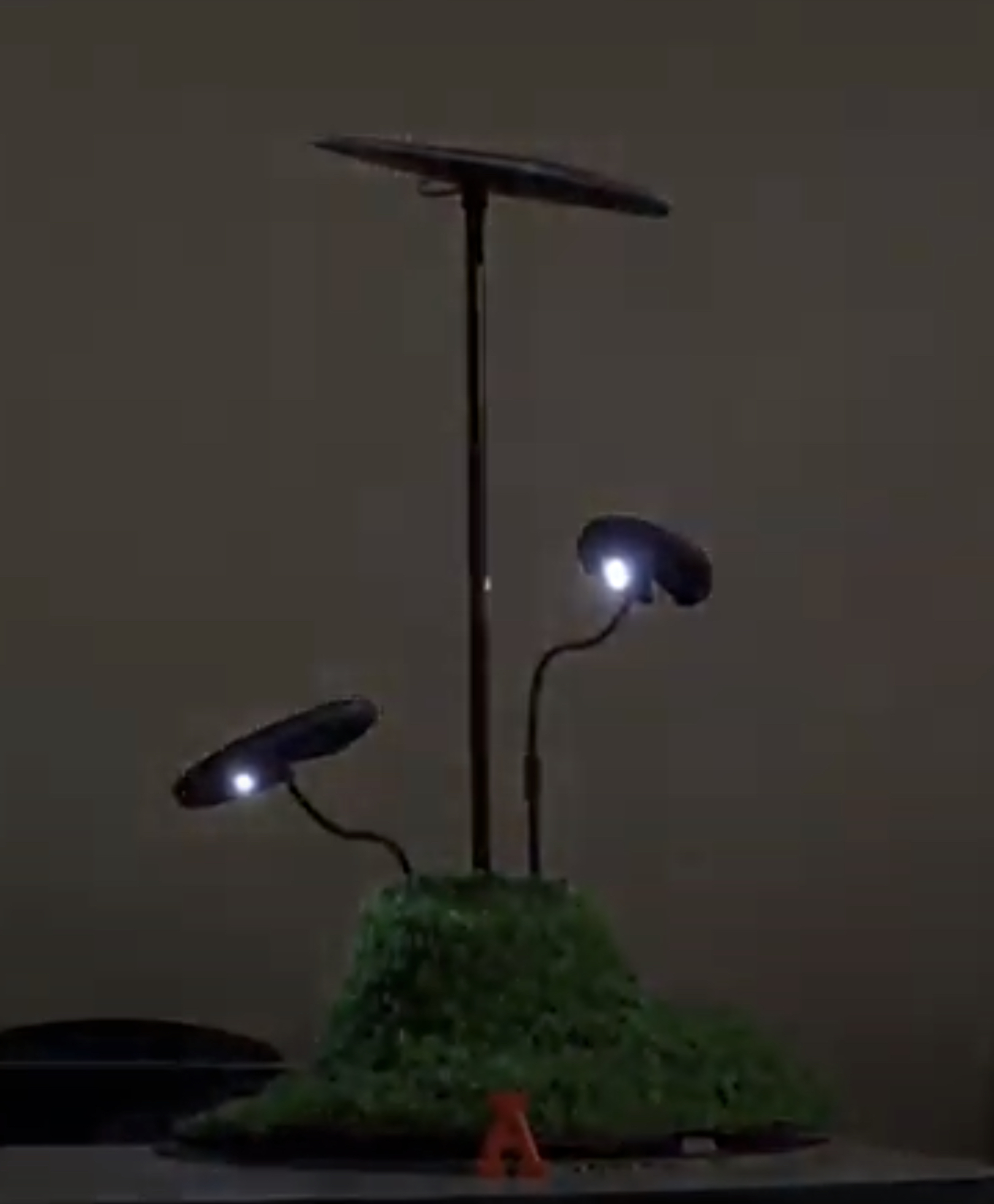
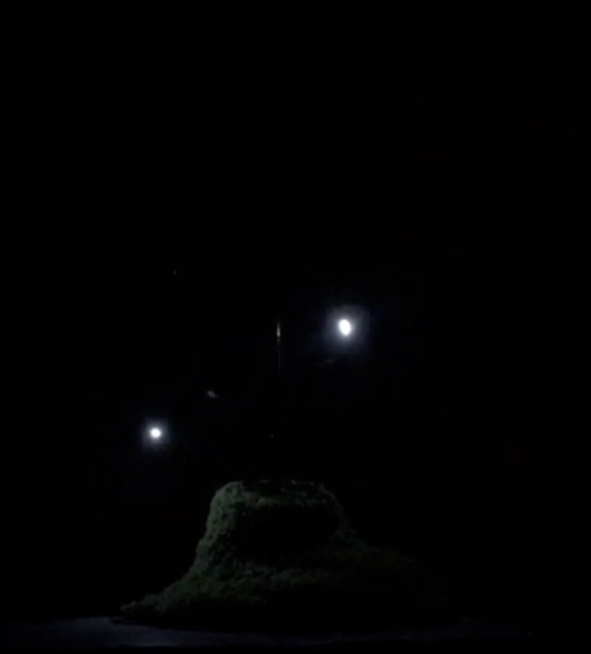
Checking the LDR and
the LEDS function
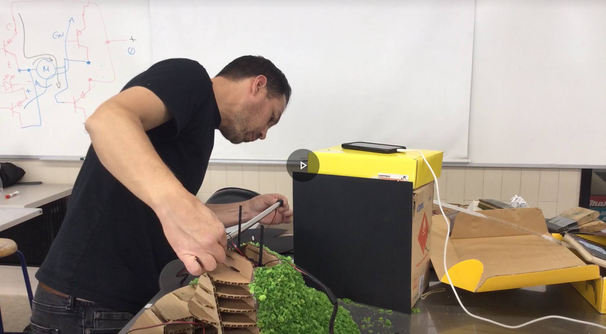
Assemble of the central
mechanism that connect the principal leaf with the servo so can turn
the solar cells toward the sun
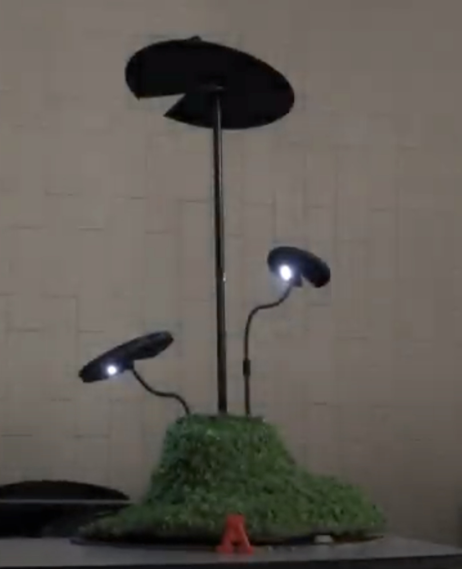
prototype
a place to re-connect