For this assignment
I want to thank Rodrigo
Shiordia who show me the basics
of Processing so I can design the interface between my computer
and my Hugodino to move the servo who rotates de axis of the
central structure that moves the solar panels of my project.
Processing, Arduino IDE, Hugodino PCB
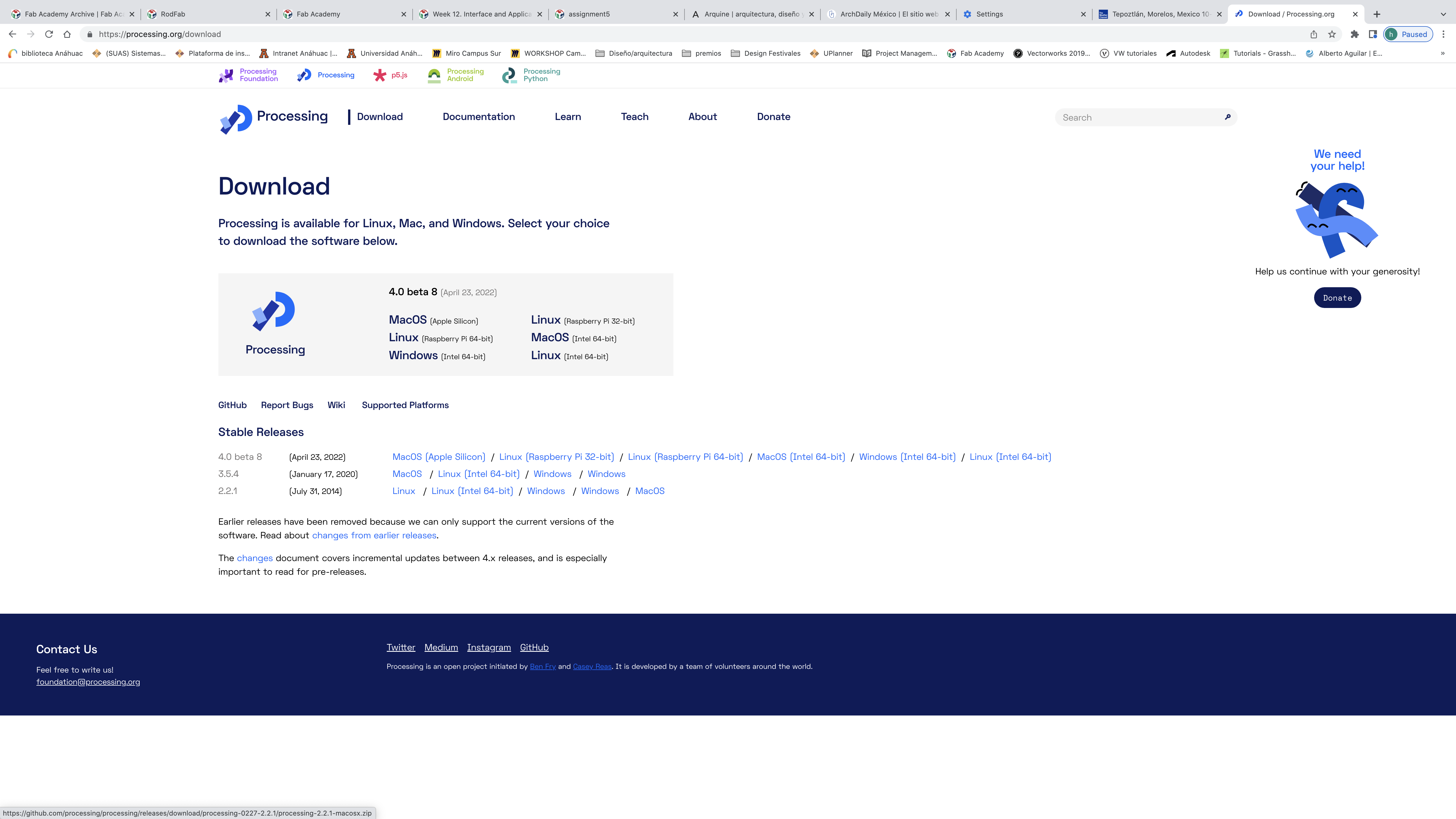

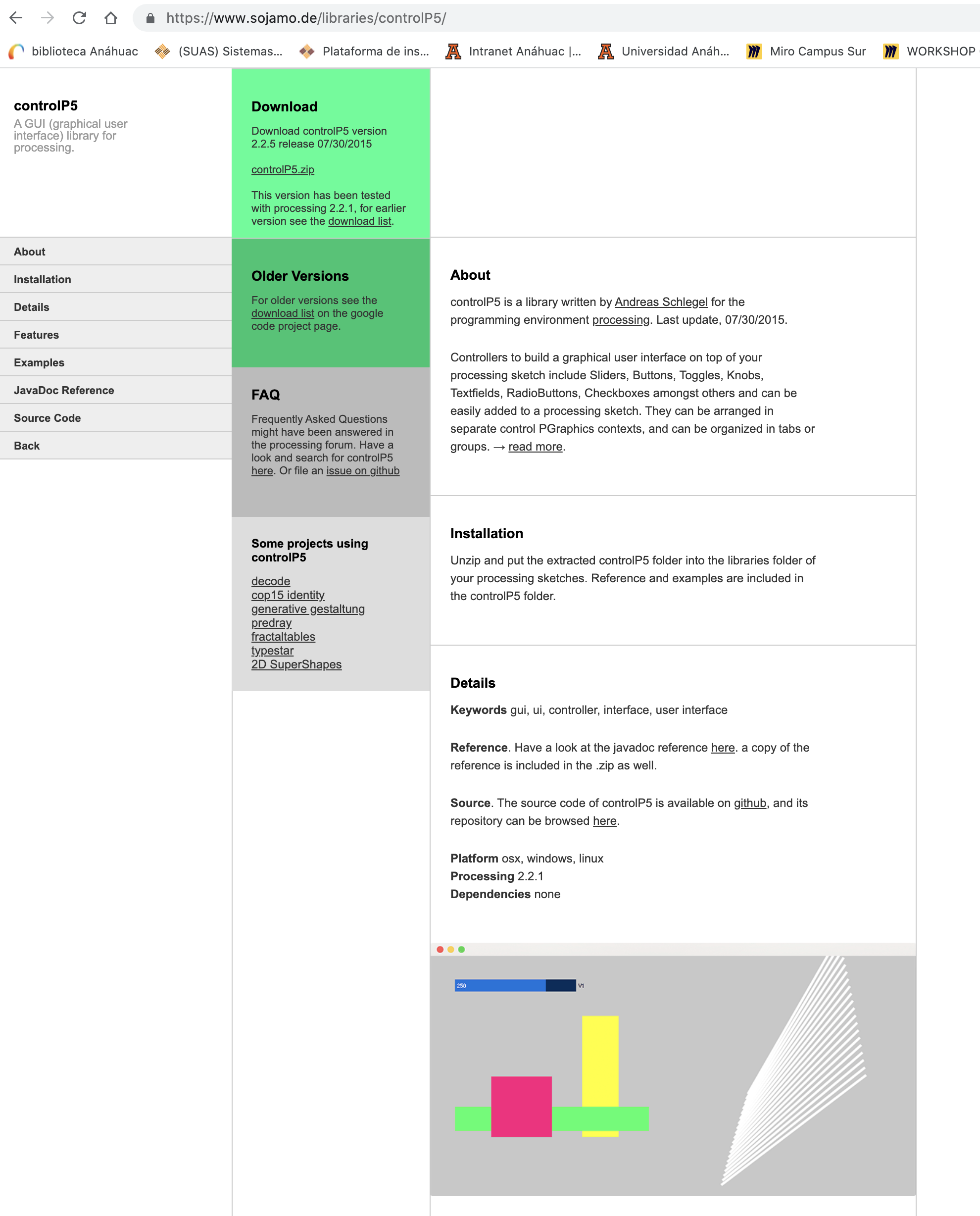
Then I download
controlP5 to had the library of graphic design that I can use in my
interface between the computer and my board, after download
controlP5 yo need to move the folder "controlP5" into the library
folder of Processing to install it, if Processing is open you have
to quit and reopen it:
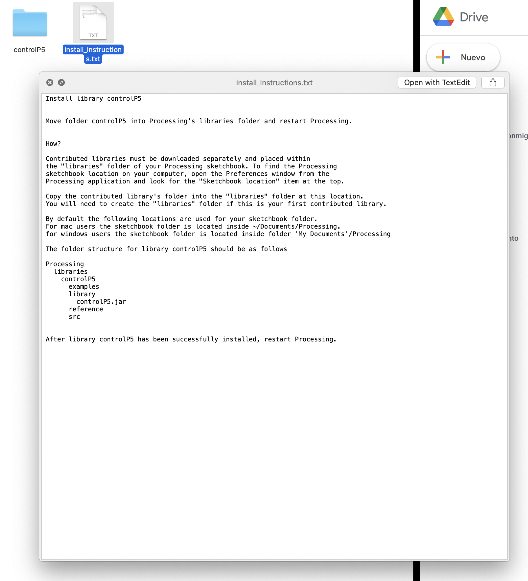
Instructions in detail
to install controlP5
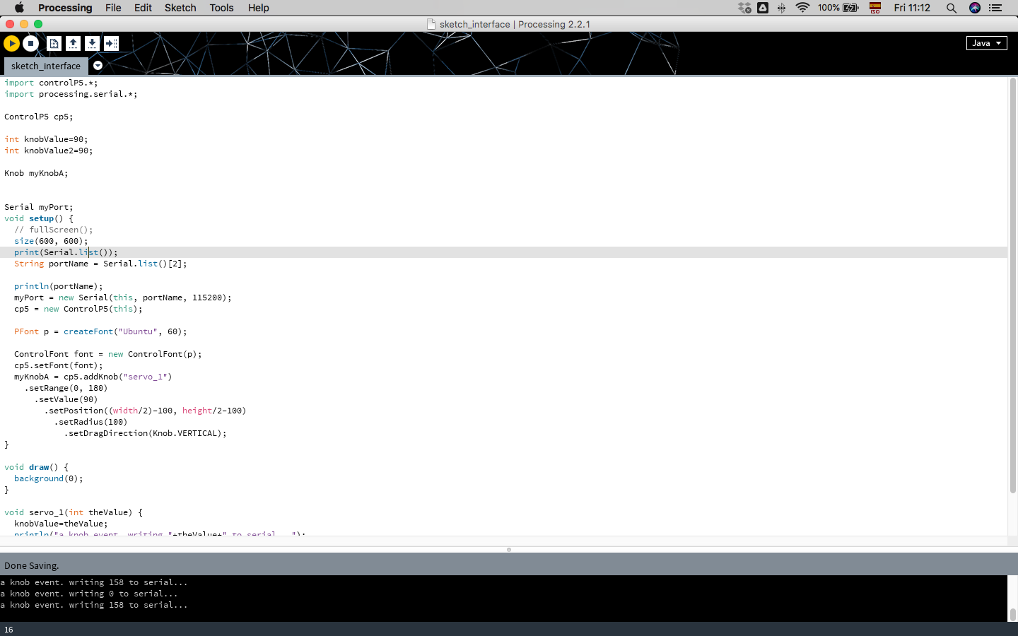
Here is the Processing
interface, it´s like Arduino but to design graphics that will
interact with my board. In the "size" line we are going to define
the size of the window where we are going to put our "controller" of
the servo, in this cse is 600 by 600.
The serial (portname)
is number 2, because in the list of ports, the USB that we are going
to use is listed in order of appearance in 3rd place, counting from
0 it will be Number 2.
Open port at 115200
Then we have the
settings and position of the control inside the window of 600x600
here´s the Processing
CODE: ----------------------------
import controlP5.*;
import processing.serial.*;
ControlP5 cp5;
int knobValue=90;
int knobValue2=90;
Knob myKnobA;
Serial myPort;
void setup() {
// fullScreen();
size(600, 600);
print(Serial.list());
String portName = Serial.list()[2];
println(portName);
myPort = new Serial(this, portName, 115200);
cp5 = new ControlP5(this);
PFont p = createFont("Ubuntu", 60);
ControlFont font = new ControlFont(p);
cp5.setFont(font);
myKnobA = cp5.addKnob("servo_1")
.setRange(0, 180)
.setValue(90)
.setPosition((width/2)-100, height/2-100)
.setRadius(100)
.setDragDirection(Knob.VERTICAL);
}
void draw() {
background(0);
}
void servo_1(int theValue) {
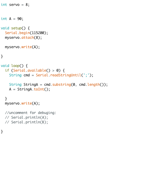
OK, we already have the
Processing code , then we need to stablished the connection to the
board and for that purpose we are going to use the Arduino IDE, here
you can see the Code, we are calling the servo into Pin 8, then the
start position is 90 because Processing has that initial position,
from now on we are going to move the position of the servo with the
interface we just design in Processing.
Here the Arduino Code to
communicate with the board: -------------------------
int
servo = 8;
int A = 90;
void setup() {
Serial.begin(115200);
myservo.attach(8);
myservo.write(A);
}
void loop() {
if (Serial.available() > 0) {
String cmd = Serial.readStringUntil(';');
String StringA = cmd.substring(0, cmd.length());
A = StringA.toInt();
}
myservo.write(A);
//uncomment for debuging:
// Serial.println(A);
// Serial.println(B);
}
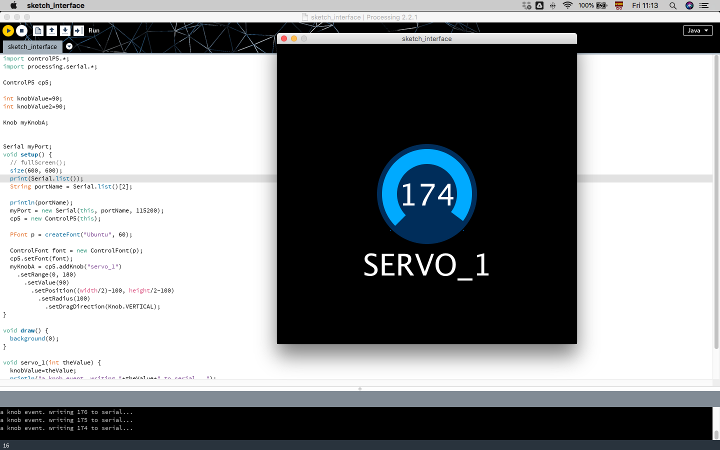
The window with the
knob design that controls the position of the servo.
In this video I´m
showing some modifications in the code that change the interface of
processing, the knob that controlls the servo, first the size of the
screen that is set to (600,600) and I´m modifying to (900,600) this
means that the window instead of being square now it´s going to look
rectangular, then the FONT size and the setvalue, this value refers
to the initial position of the KNOB, originally is set to 90 and I´m
going to chnge it to 10 and the limit of rotation from 0,180 now is
going to be 0, 150, then let´s change the diameter and position of
the KNOB, the radius has a 100 and let´s change it to 200, but then
we have to change also the position of the circle in the window
because if we left the original . setPosition((width/2)-100,
height/2-200) the new 200 radius circle is not going to fit in the
window, so, let´s change the value 100 for 200 and also the color of
the backgronund, now is set to (0) that means is black and here you
can put a RGB value like, (20, 50 , 30) and this will change the
color of the background.
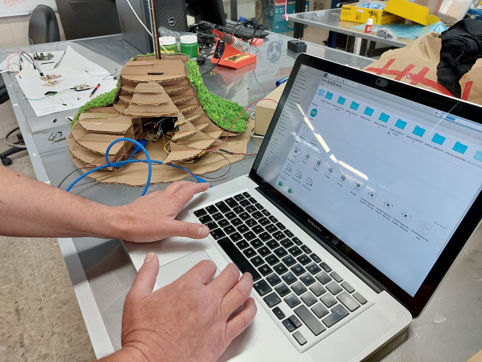
Connecting my board to
my Mac
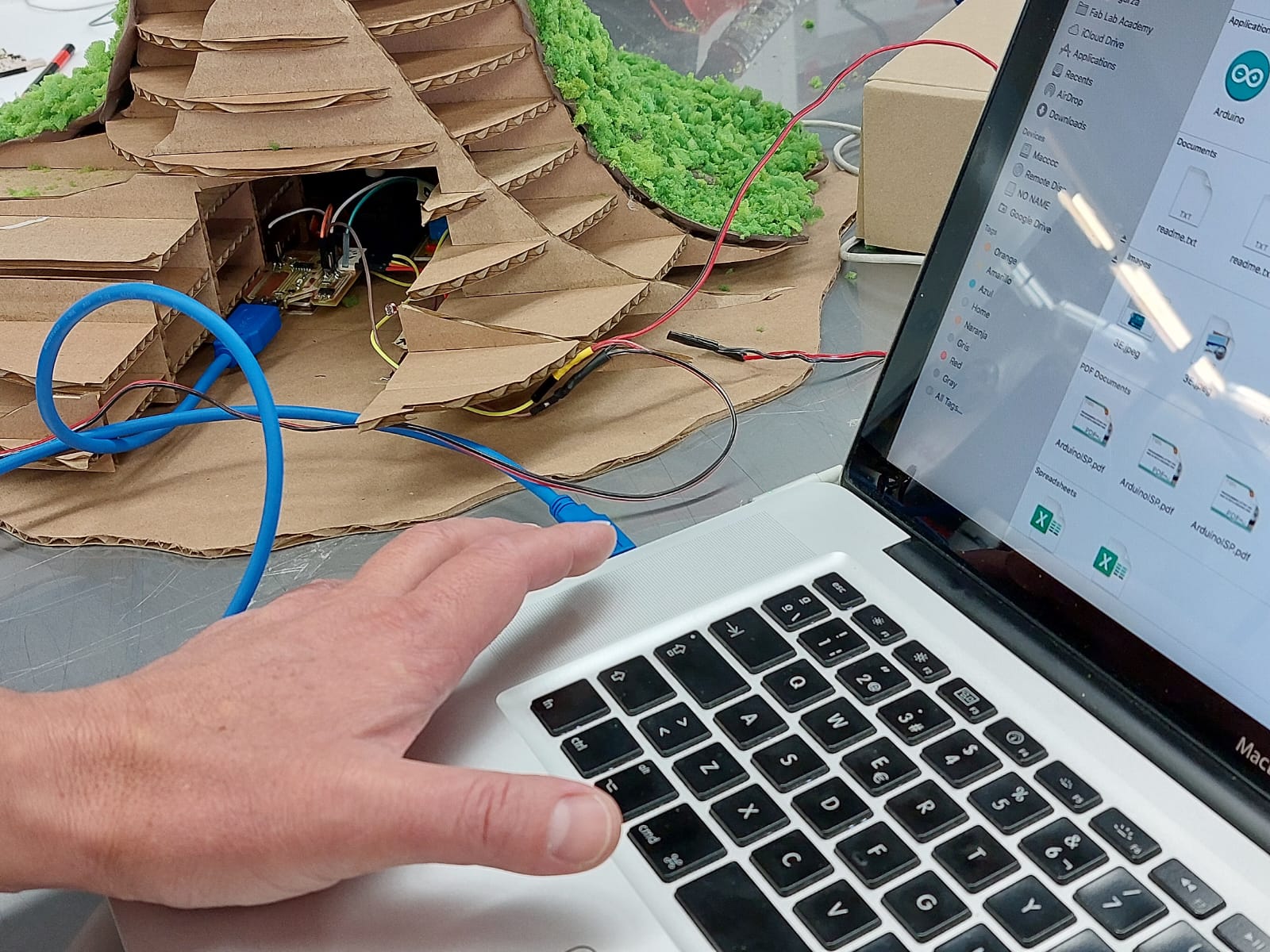
A closer look inside
the base to see that is my board connected.
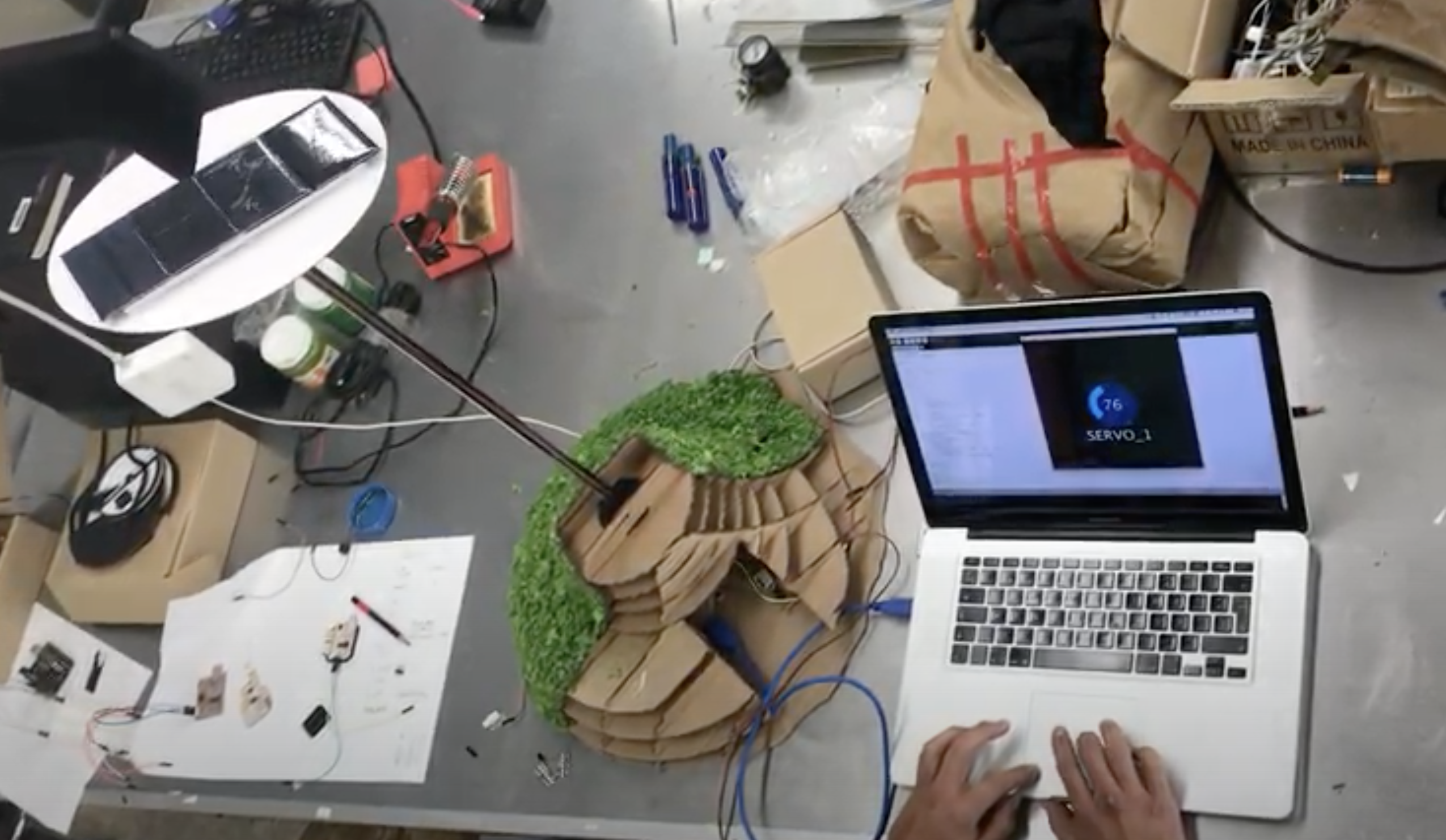
Moving the servo and
the solar panels to the 76º position
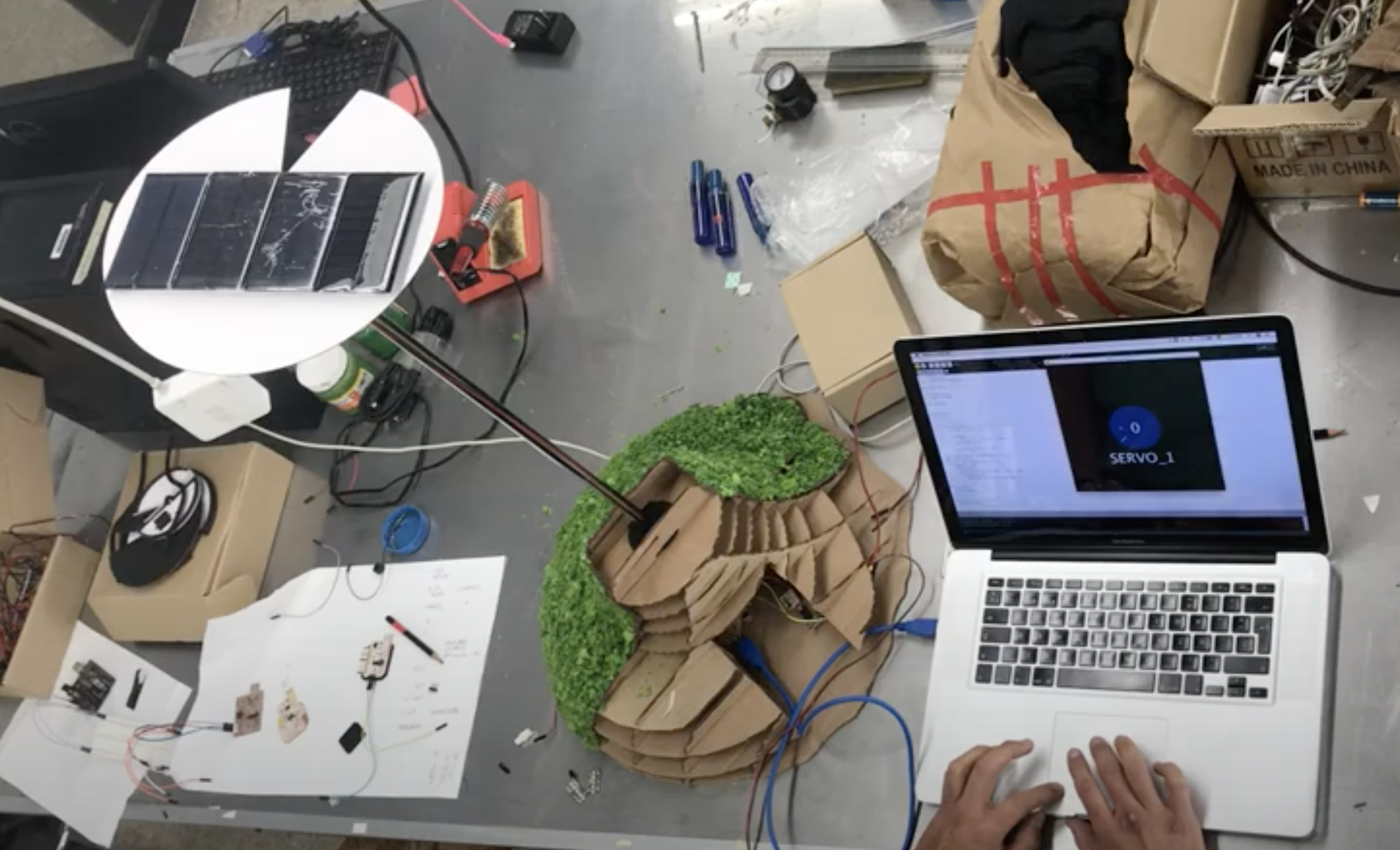
Returning to 0º
position
Here a video showing
the interface working with the servo