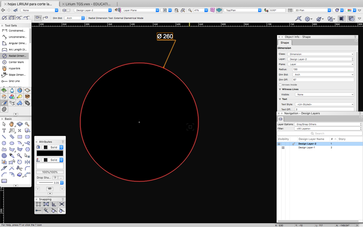
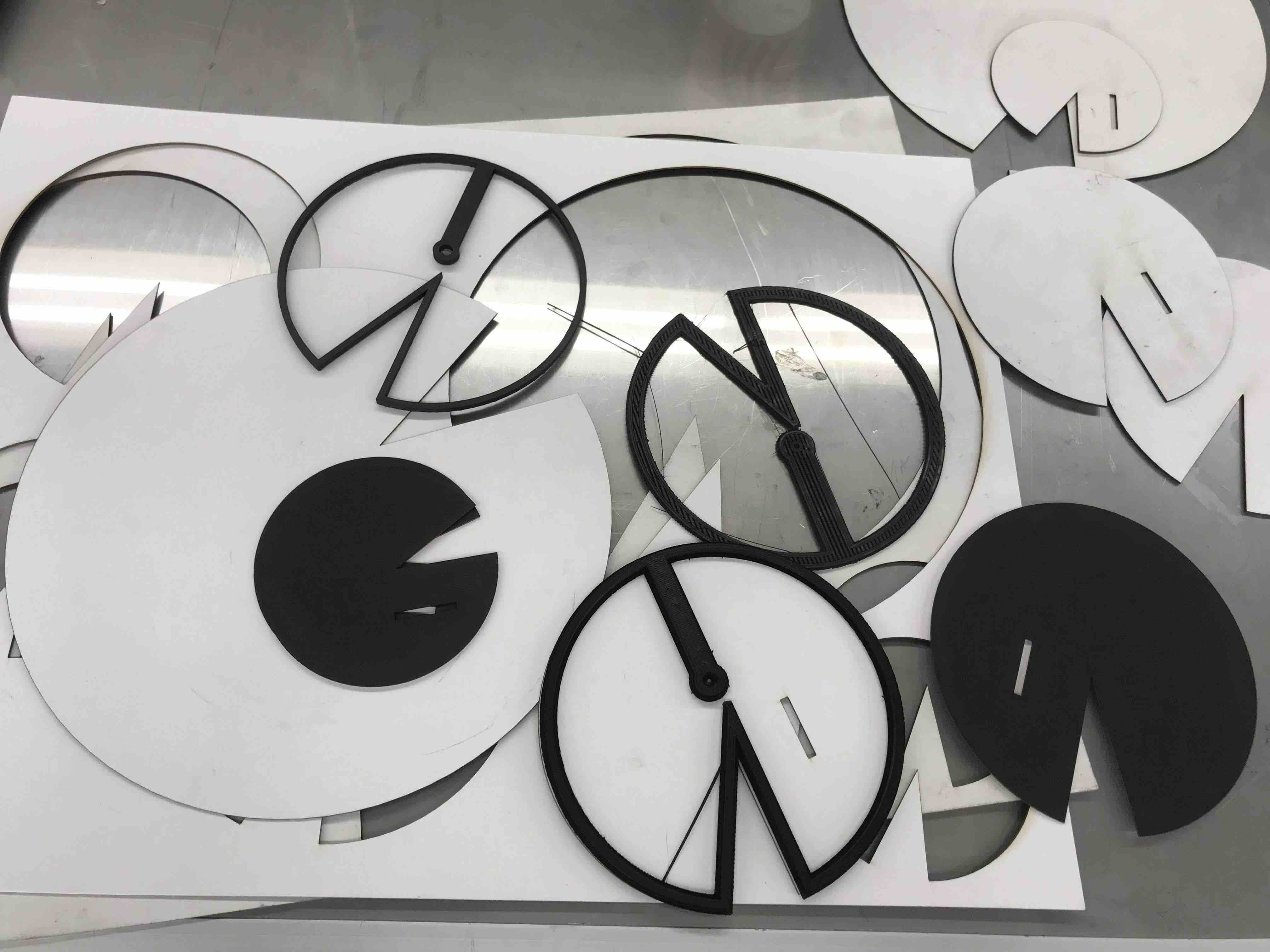
For this assignment
I will draw the leafs that would be part of the upper
system of my project, there will be the solar cells and the LED
lights, so in Vectorworks I will draw the circles and clip the
pacman mouth like distinct form of the lirium leaf and with that
shape defined, I will make in Fusion360 the 3D perymeter of the
leafs, with both pieces finsihed I would be able to shape the
leafs and put the electrical system on them.
Vectorworks,
Fusion360
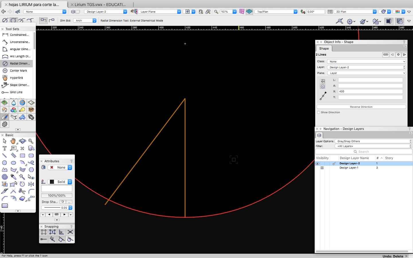
I draw a shape to cut
it form the circle, this will be the "mouth" of the leaf
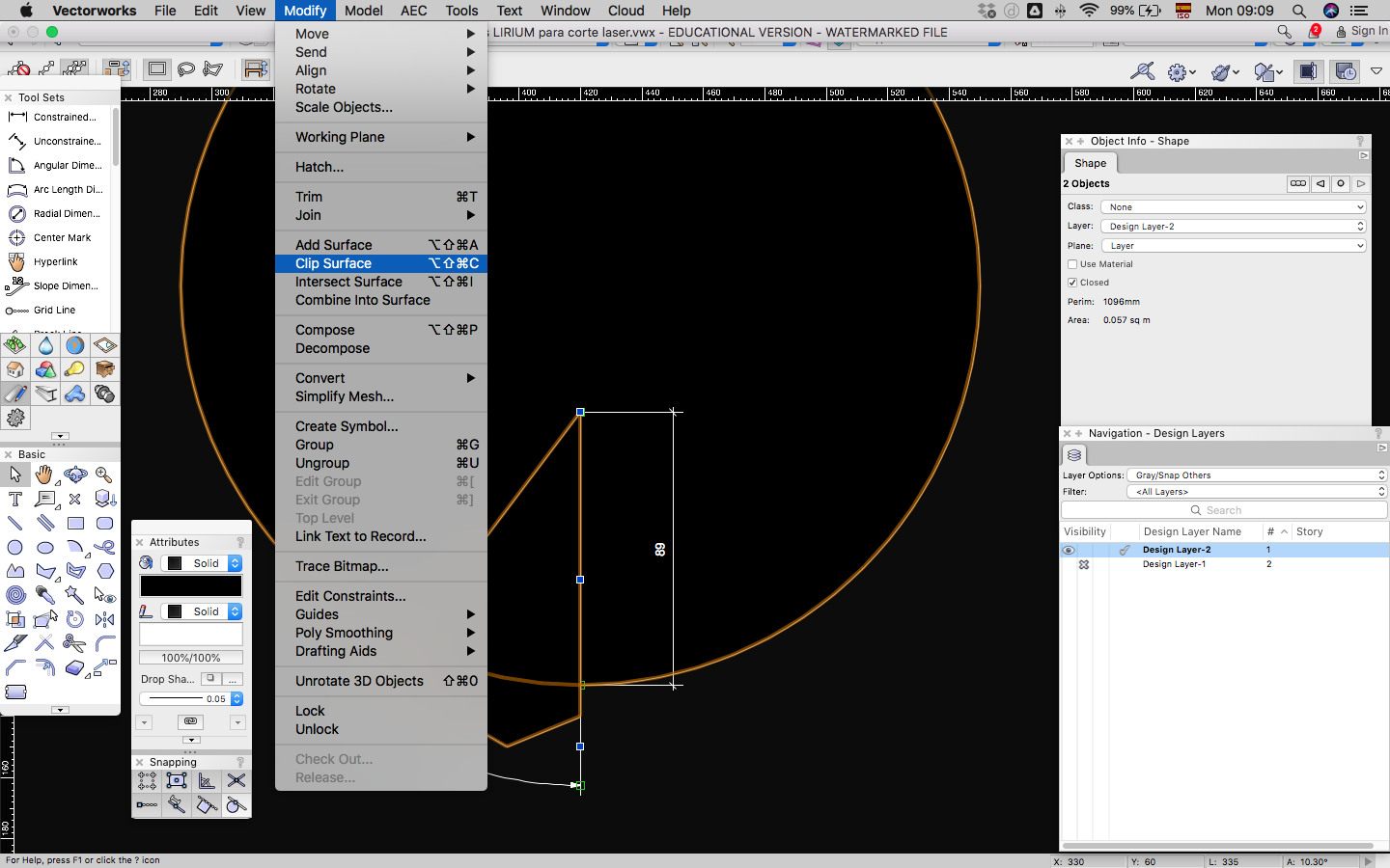
With the clip Surface
action, you will be able to remove the "triangle" I made to cut it
from the circle
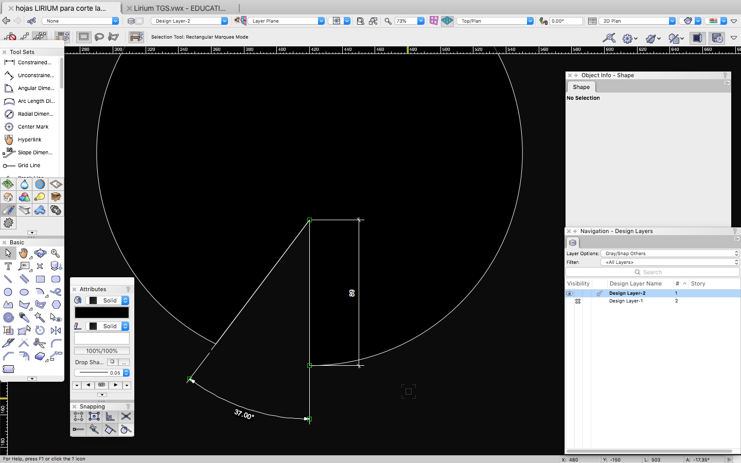
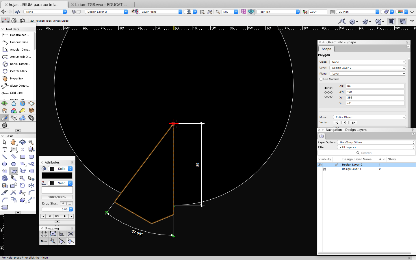
Here is the resulting
shape; the circle without the mouth like shape
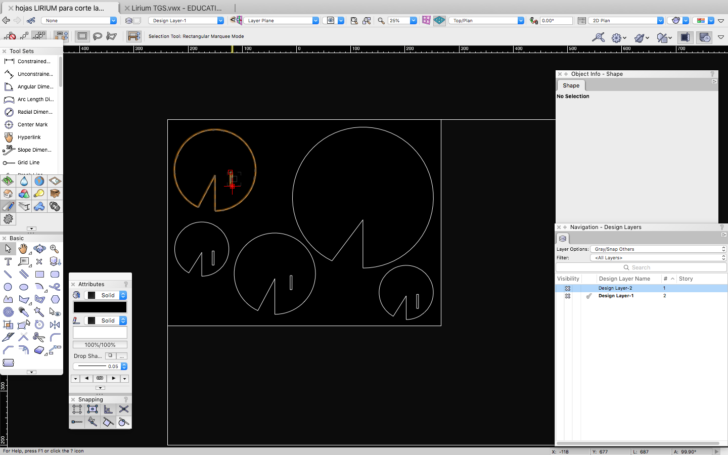
Do the same with the
rest of the pieces and draw a rectangle that measure the size of the
cartonboard you are going to use to cut your pieces
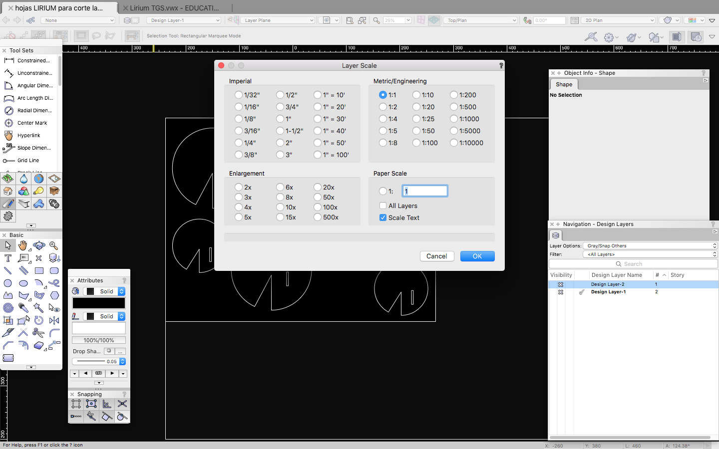
Scale 1:1 and in mm,
this is important
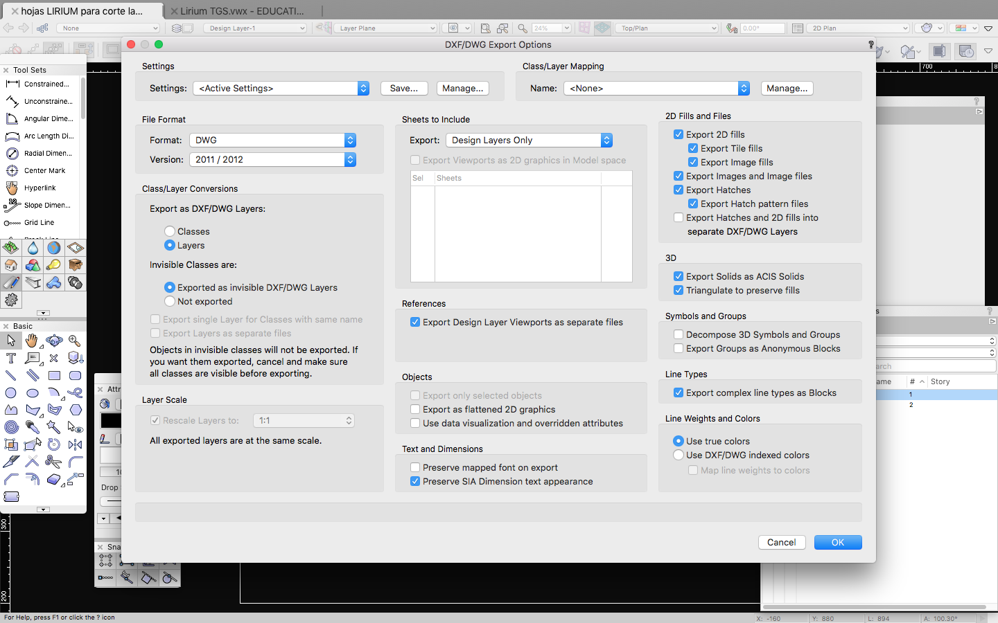
Export the archive to
.DWG to open it later in autocad.
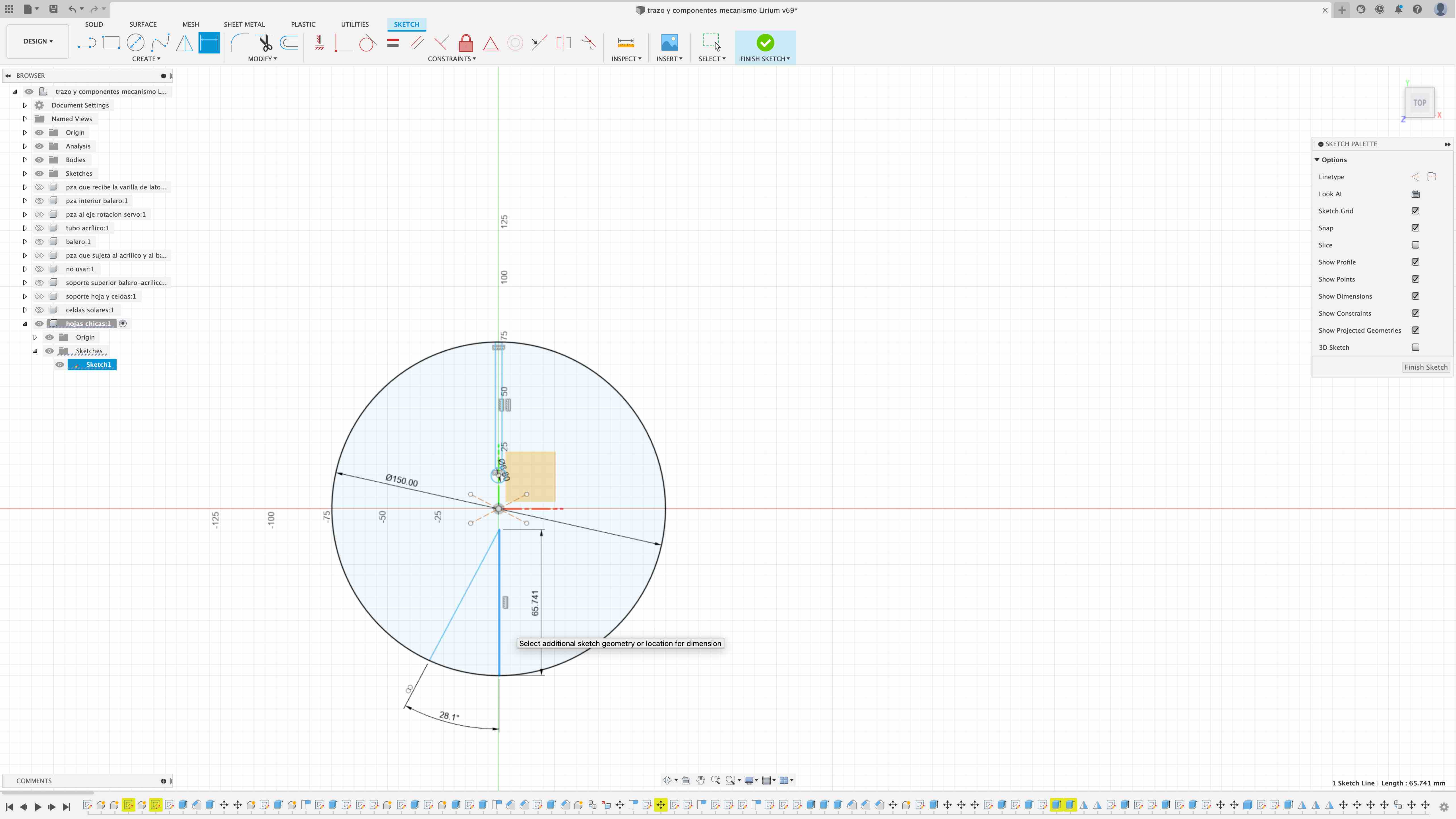
In fusion360 I draw the
circle that will be the perimeter of the leafs, the triangle that
would be the pacman mouth like caracteristique lirium shape and the
inner circle with its support arm,
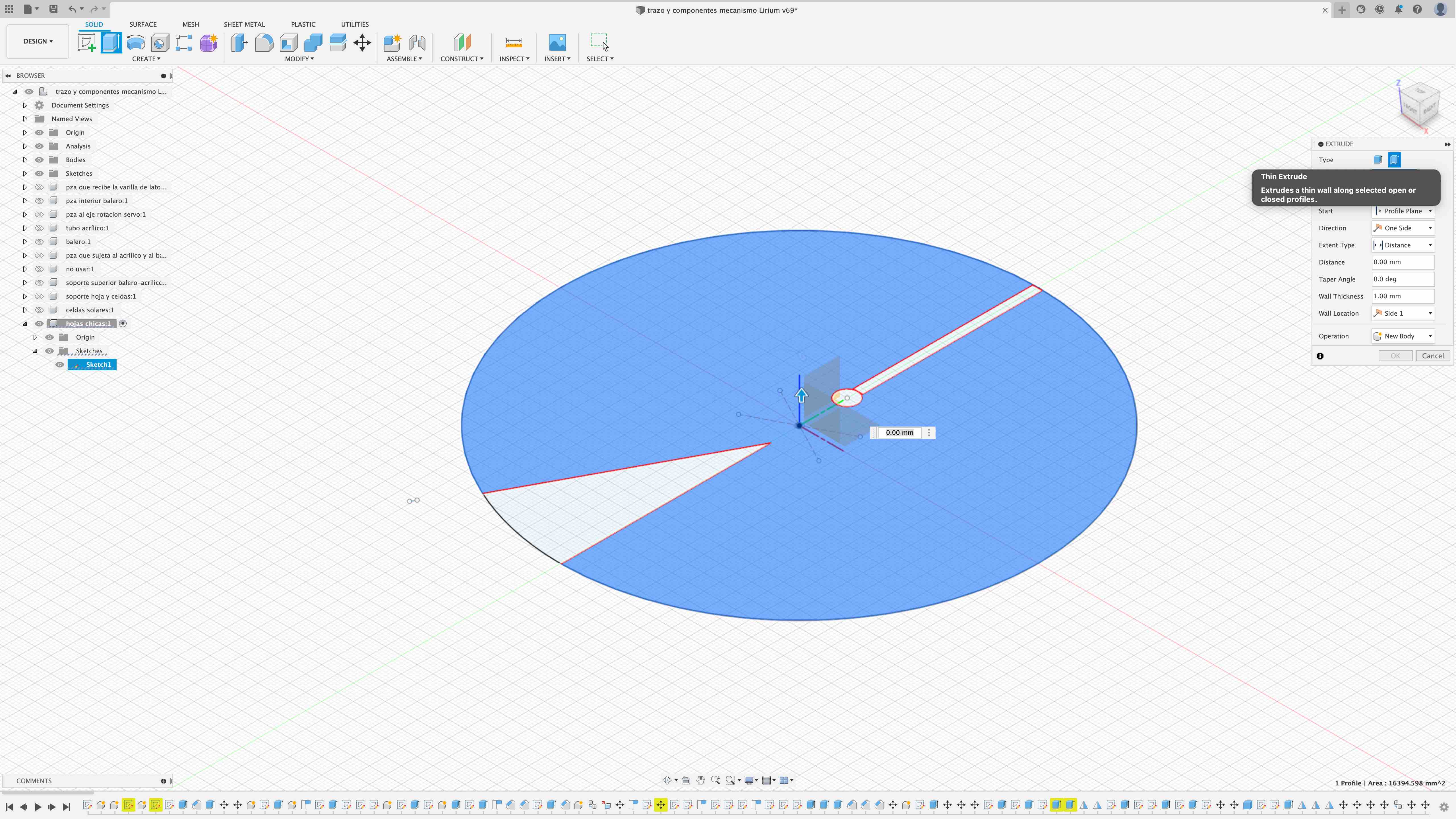
Then with the tool
extrude-thin extrude i will extrude only the perymeter of
the leaf: in the window of the tool you need to specify the wall
thickness and the distance (the high)
of the extrussion, its important to choose the direction
and the Wall location because with this you
specify if the thickness of the extrussion would be inside or
outside the line, in this case I choose side 1
than means in the interior because I need
the thickness of the extrusion to be inside the limits of the
circle.
Here we can see the
extrussion of the leaf perymeter
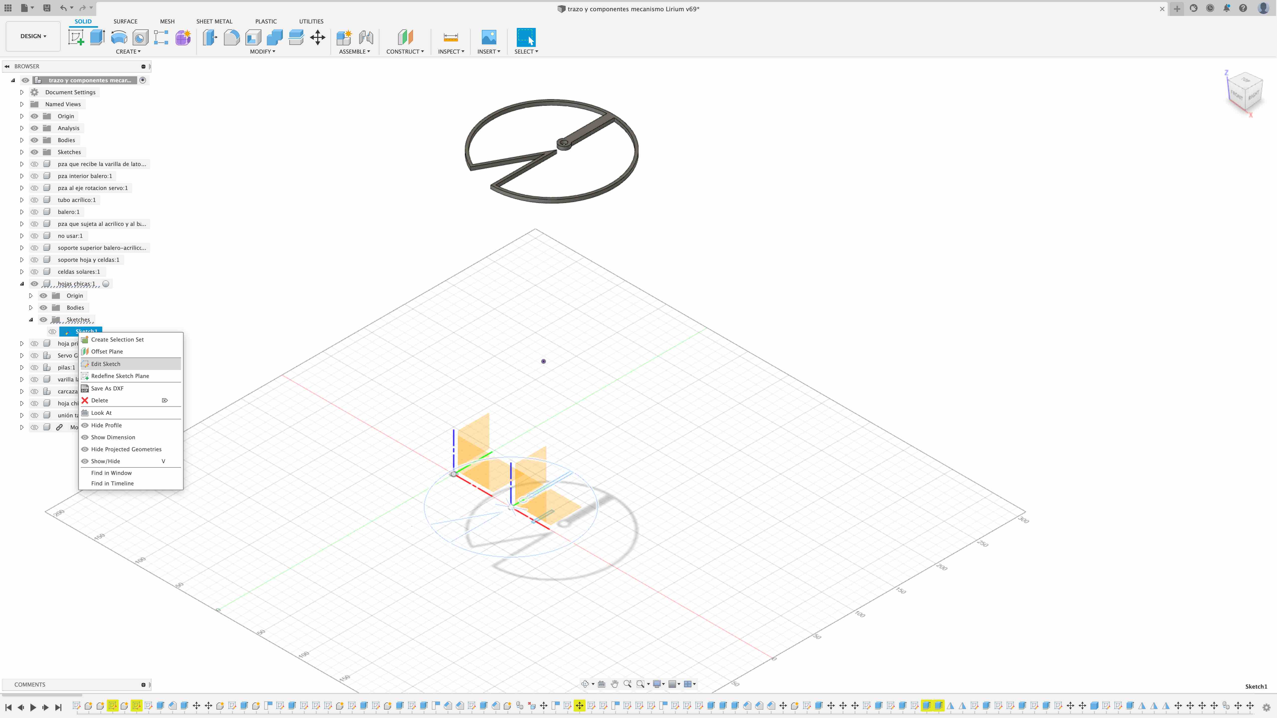
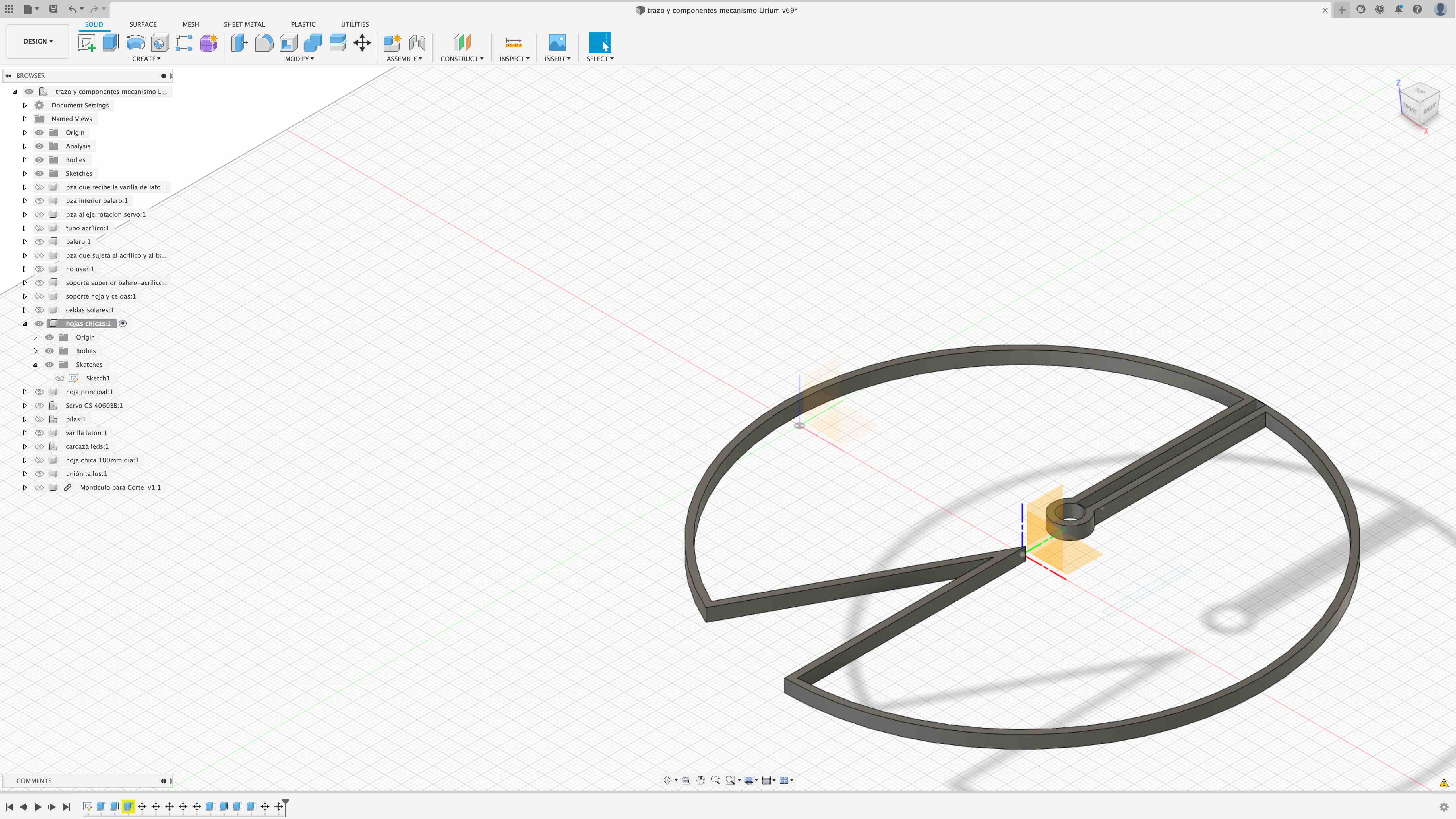
One really good thing
about fusion360 is that you keep the original
sketch and the "body"(the body is the 3d object that result from
extrude the sketch), that means that I can go to the original sketch
and modify something, and the body, in this case the extrusion would
be updated according to those modifications. You can see this in the
left menu, there, I´m selecting "edit
sketch" of the sketch 1 of the "hojas
chicas" component.
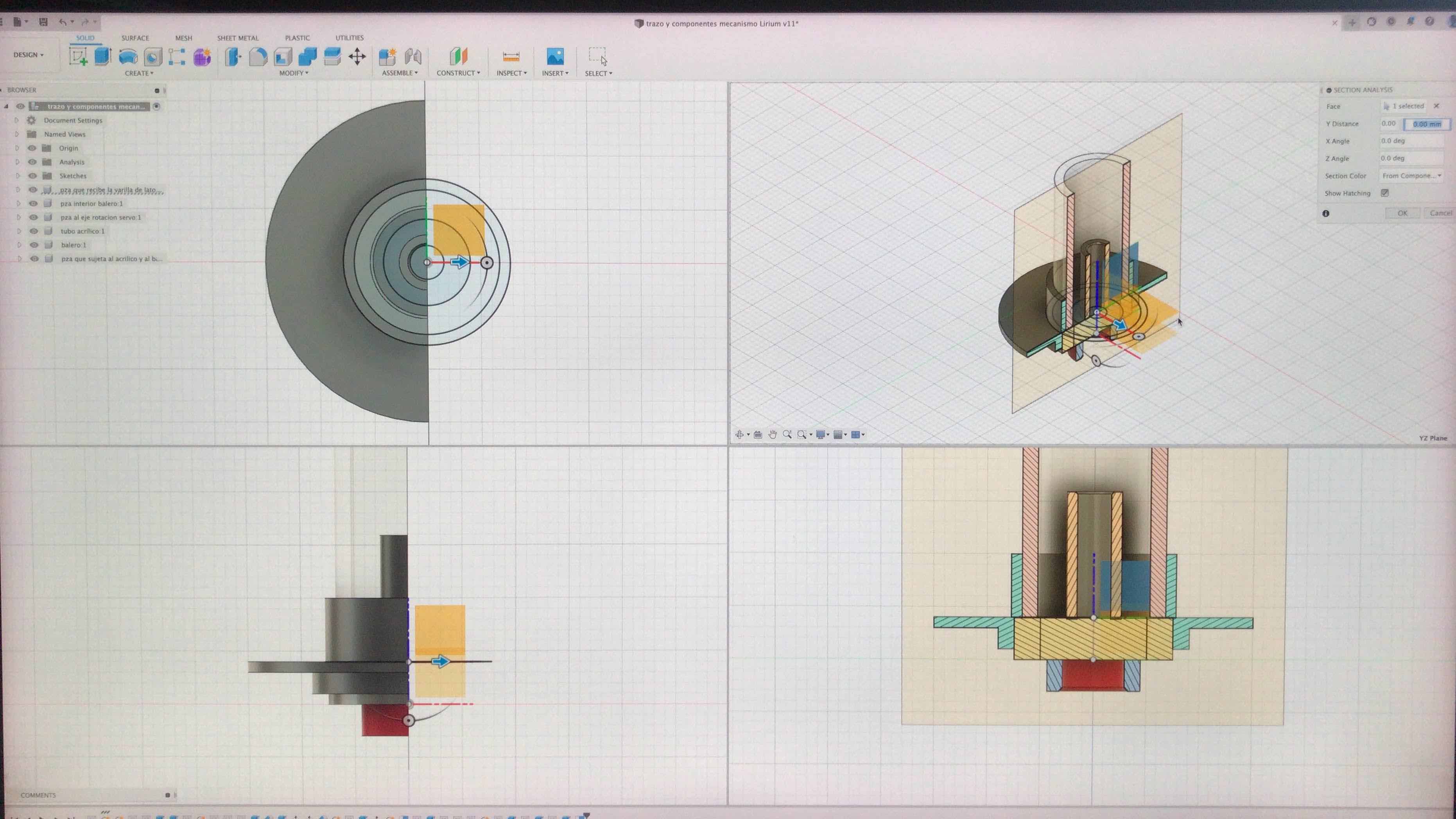
Another sample of some
3D components of my final project, here I assemble the rotation
pieces. Using the "section analysis" that is inside the INSPECT menu
we are able to see a longitudinal cut of the components to see if
everything is in it´s place and nothing interferes, if needed, I can
modify some parameters to change some dimensions.
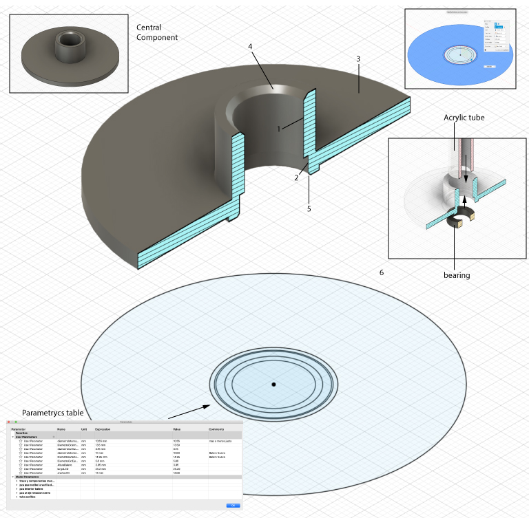
To model in 3D this
component, the Central Component, I knew in advanced that I will
need an Acrylic Tube and a Bearing, not quite sure about the
measures of those 2 objetcs but sure that I need to consider them
because one is going to act s the support of the upper leaf and the
later will be used as the rotating system. So, first I start making
my parametrycs table because all the circles of the Central
Component will be affected by each other, and also they can be
affected by the percentage of the contraction of the plastic (ABS or
PLA) in wich the component will be printed, so I write the
parametrics of the bearing, the acrylic tube among others, Then I
started with the sketches, here in fusion 360 is prefer to start
drawing sketches, it means that you start drawing basic forms
like circles, lines, rectangles, etc and you can put the dimension
of that sketch directly or using a parameter, in my case I use
parameters , then, it´s moment to make the 3D, to do so you can
extrude (pull) your sketches and you can choose from 2 options EXTRUDE
or THIN EXTRUDE this means that you can extrude the surface
of the circle or just the "perimeter" in my model I use both
options, the outer circle had a EXTRUDE option and the inner
ones the THIN EXTRUDE and when you select wich option you
need you specify the distance, angle and direction, this means that
you can "pull" in one or in two sides of the plane at once. After I
define this operations I made a chamfer in the edge where the
acrylic or the bearing will be introduce, this helps to avoid
resistance when introducing the objects into the Central Component.
To check if everything looks fine and fit into place I use the
Section Analysis tool to cut longitudinally the object.
1.space where the
Acrylic tube is going to fit
2.space where the
bearing is going to fit
3.round plate that will
join the central object to the base
4.Upper chamfer, to
allow the acrylic tube to fit better
5.Bearing chamfer, to
allow the bearing to fit better
6.Sketches, the initial
sketches of the design that later I will extrude to form the 3D
model