almost 2 years later, when we return to the lab.....
and the link to the group assignment is: FabLabCDMX.
For this
assignment I made a new PCB for the LDR that will function
sensoring the amount of light so I can program the leds of my
project to turn ON when is getting dark and to turn OFF when
there´s more amount of light.
Eagle, Modela, PCB, ,Arduino UNO, Arduino IDE, Hugodino, LDR, LEDS,
The schematic for
my LDR board
I left 3 pins out
when draw the outline, I´m not going to use them.
I use MODS to set
up the Modela for milling my PCB
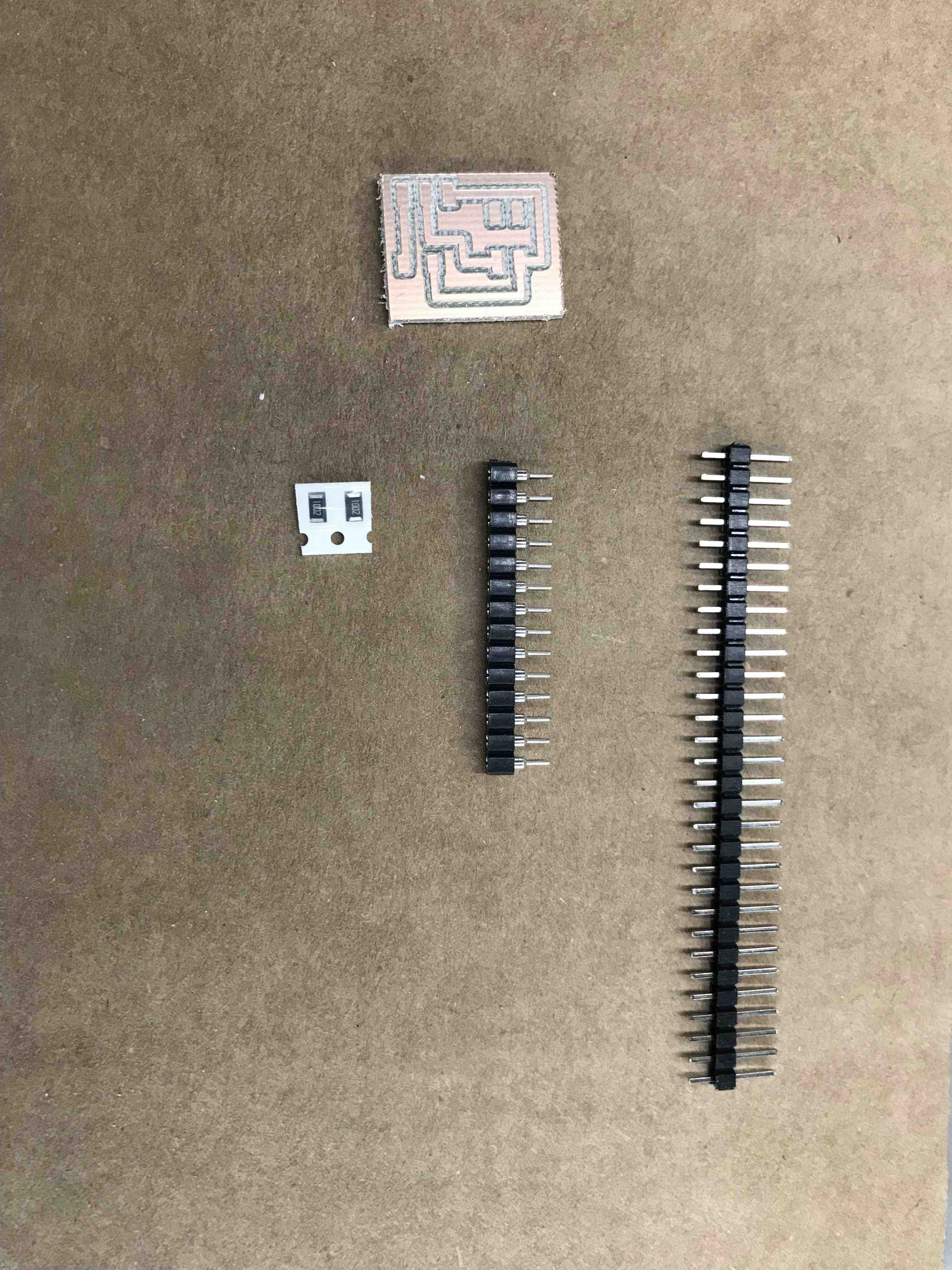
The board and the
components I´m going to weld on it.
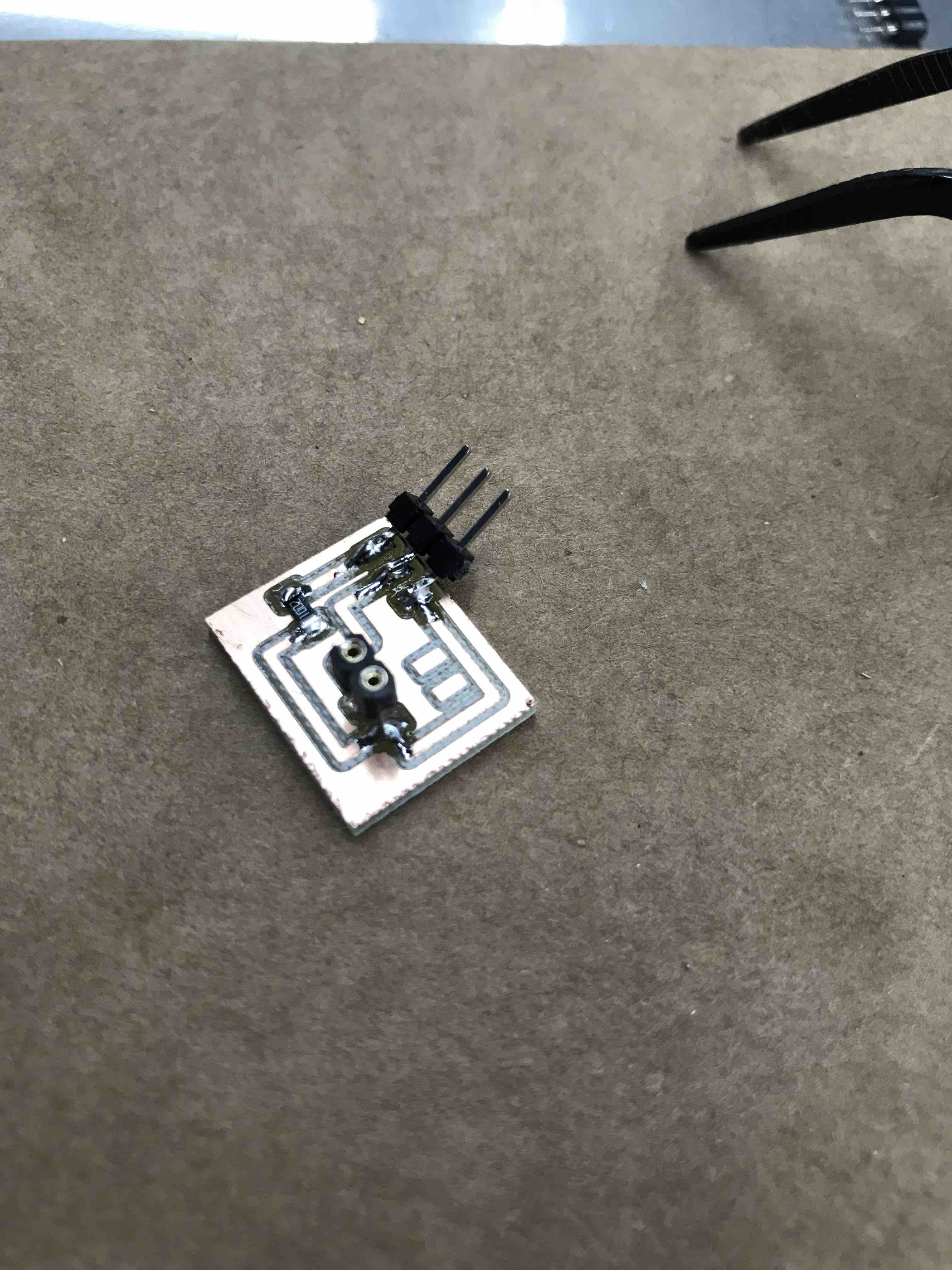
Here´s the LDR
board finished with the pins to connect the LDR sensor and the
pins to the PCB and one resistor
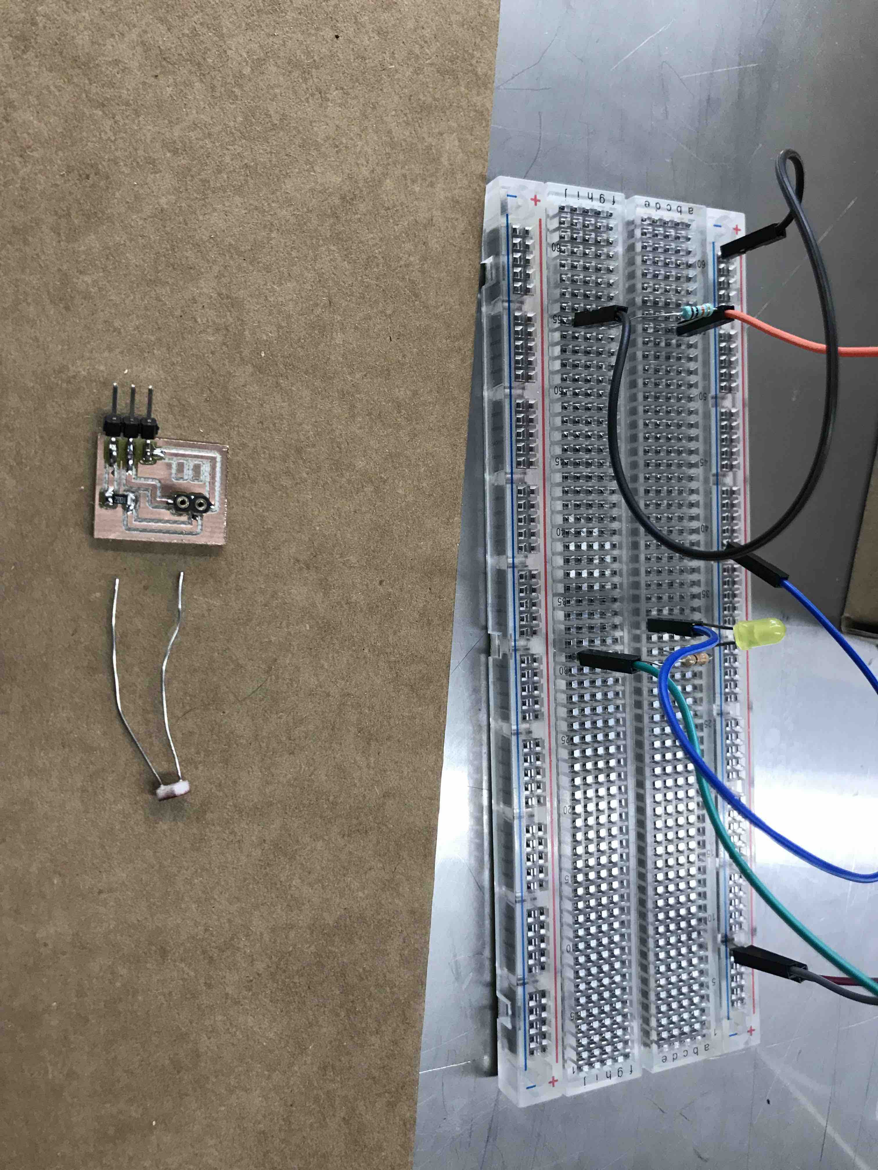
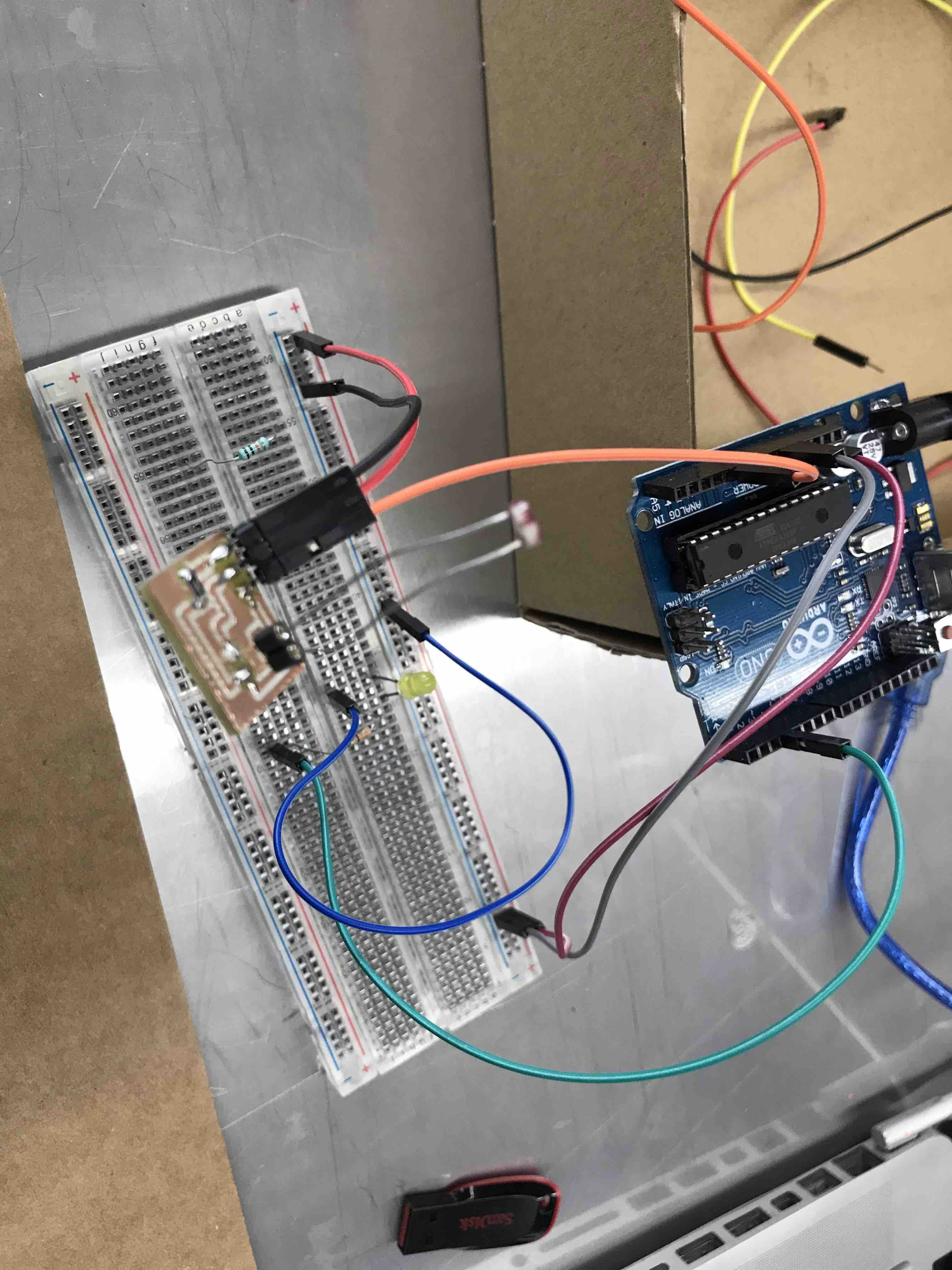
First , I´m going
to test my LDR board with ARDUINO before using it with my board
to check if there are some issues regarding the correct function
of the LDR sensor
Here is the
original CODE using ARDUINO to test the LDR sensor
int ldr=5;//Set
A0(Analog Input) for LDR.
int value=0;
void setup() {
Serial.begin(115200);
pinMode(3,OUTPUT);
}
void loop() {
value=digitalRead(ldr);//Reads the Value of LDR(light).
Serial.println("LDR value is :");//Prints the value of LDR to Serial Monitor.
Serial.println(value);
if(value<300)
{
digitalWrite(3,HIGH);//Makes the LED glow in Dark.
}
else
{
digitalWrite(3,LOW);//Turns the LED OFF in Light.
}
}
Everything works
fine and now I´m ready to connect it to my board.
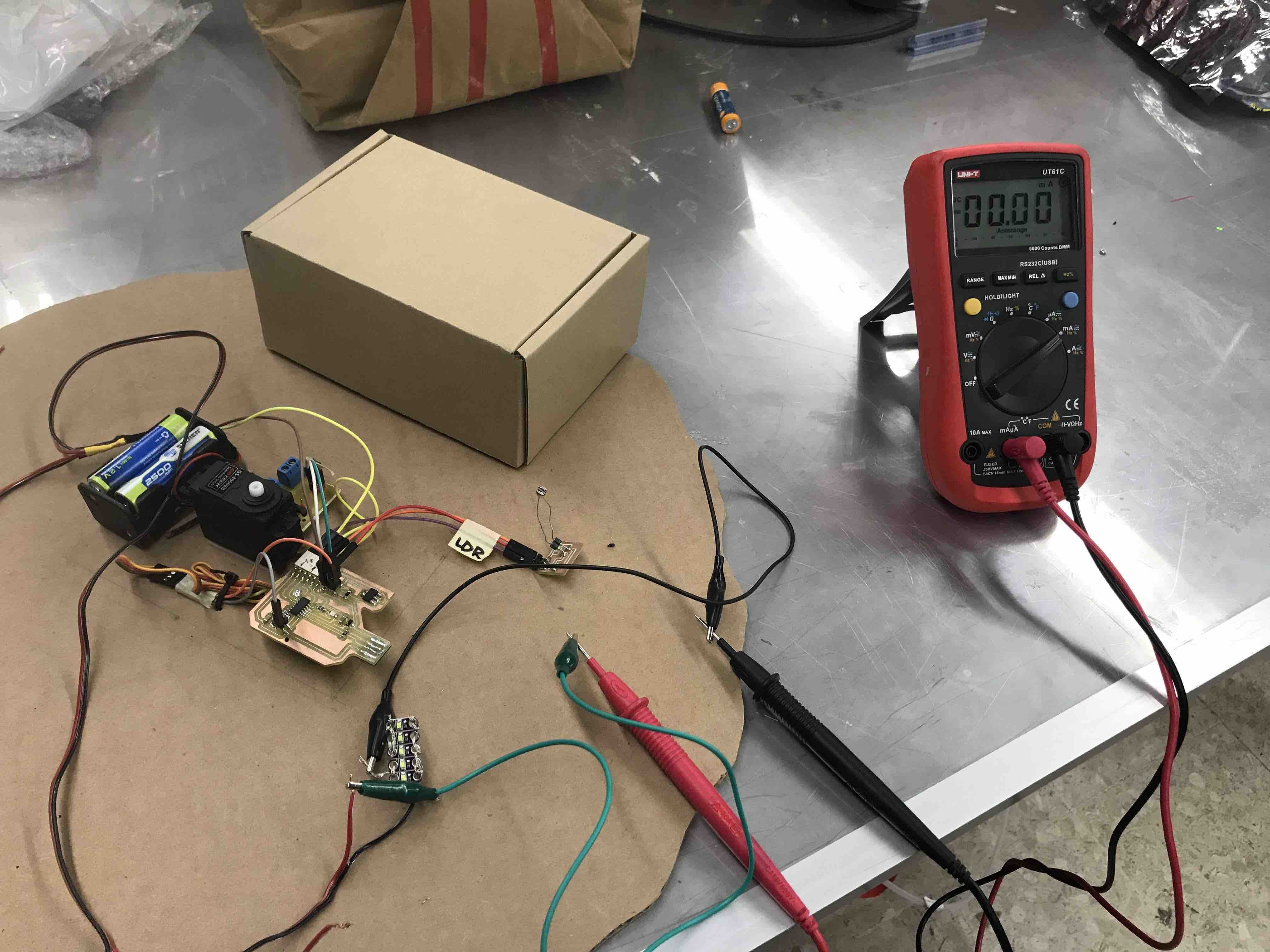
Everything
is connected, the batteries, the LDR, my HUGODINO board and
the leds through a voltmeter to did the group assignment.
This is the code I
use to test the LDR sensor
/*


  https://www.arduino.cc/en/Tutorial/BuiltInExamples/Blink
*/
int ledpin = 9;
int ldr=5, aux;
// the setup function runs once when you press reset or power the board
void setup() {
  // initialize digital pin LED_BUILTIN as an output.
  pinMode(ledpin, OUTPUT);
  pinMode(ldr, INPUT);
}

// the loop function runs over and over again forever
void loop()
{
  aux=digitalRead(ldr);
  /*aux=!aux;
  digitalWrite(ledpin,aux);*/
  if(aux==0)
  {
    digitalWrite(ledpin, HIGH);
  }
  else
  {
    digitalWrite(ledpin, LOW);
  }
  //delay(1000);

}
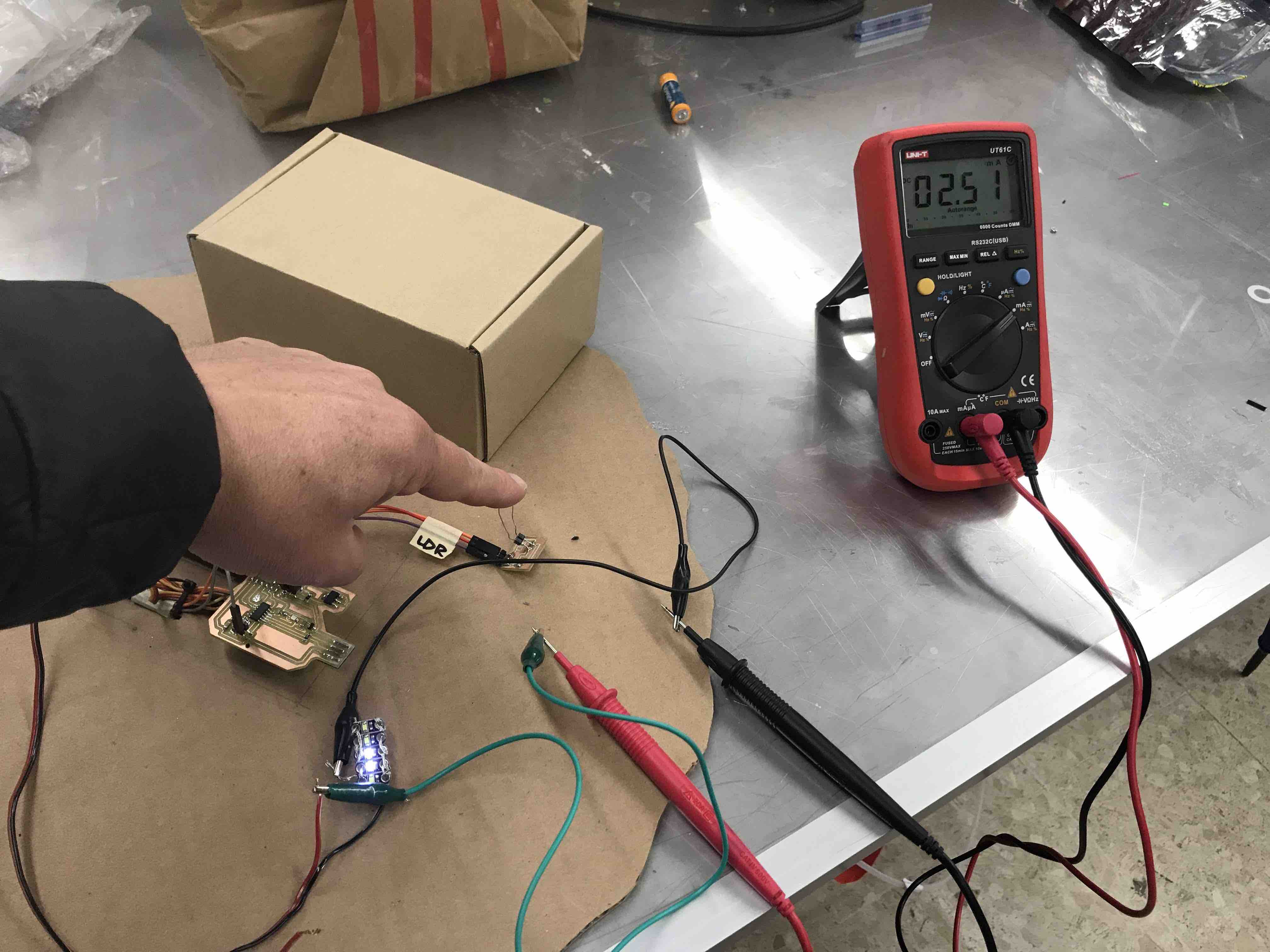
Testing the input
with the voltmeter, the LEDS are ON and the mA in 2.51
int
ledpin = 9;
int LDR = 5;
int aux;
int servo = 8;
int angle;
int pwm;
void setup()
{
// put your setup code here, to run once:
pinMode(ledpin, OUTPUT);
pinMode(LDR, INPUT);
pinMode(servo, OUTPUT);
}
void loop()
{
aux = digitalRead(LDR);
if(aux==0)
{
digitalWrite(ledpin, HIGH);
}
else
{
digitalWrite(ledpin, LOW);
}
// put your main code here, to run repeatedly:
for (angle = 0; angle <= 40; angle += 5) {
servoPulse(servo, angle); }
delay(5000);
aux = digitalRead(LDR);
if(aux==0)
{
digitalWrite(ledpin, HIGH);
}
else
{
digitalWrite(ledpin, LOW);
}
for (angle = 40; angle <= 80; angle += 5) {
servoPulse(servo, angle); }
delay(3000);
aux = digitalRead(LDR);
if(aux==0)
{
digitalWrite(ledpin, HIGH);
}
else
{
digitalWrite(ledpin, LOW);
}
for (angle = 80; angle <= 170; angle += 5) {
servoPulse(servo, angle); }
delay(3000);
aux = digitalRead(LDR);
if(aux==0)
{
digitalWrite(ledpin, HIGH);
}
else
{
digitalWrite(ledpin, LOW);
}
for (angle = 170; angle >= 0; angle -= 5) {
servoPulse(servo, angle); }
delay(3000);
}
void servoPulse (int servo, int angle)
{
pwm = (angle*11) + 500; // Convert angle to microseconds
digitalWrite(servo, HIGH);
delayMicroseconds(pwm);
digitalWrite(servo, LOW);
delay(50);
}
IN THIS CODE, THE
"READING" OF THE LDR SENSOR, TURNS ON AND OFF THE LEDS, WHEN
THERE´S LIGHT THE LEDS ARE OFF AND WHEN THE AMOUNT OF LIGHT
POINTING TO THE LDR DECREASE, THE LEDS TURN ON, THIS SENSOR OR
THIS RESISTOR LET THE CURRENCY PASS THROUGH THE CONNECTION TO
THE LEDS IT´S LIKE A SWITCH, WITH LIGHT CUTS THE ELECTRICITY AND
WITHOUT LIGHT LET THE ELECTRICITY GOING THROUGH THE CONNECTIONS
THAT TURNS THE LEDS ON. THAT´S WHY YIU CAN SEE IN THE HEADER
VIDEO THAT THE VOLTAGE GOES UP WHEN YOU PUT YOUR FINGER OVER THE
LDR.
here is another
video besides the one at the header where using the input of the
LDR (Light Dependent Resistor) sensor to turn of and on
the LEDS