First we program the
board with a programmer with a EDBG file that we also download
following the instructions that you can find in the
Adrian
Torres / SAMDINO.
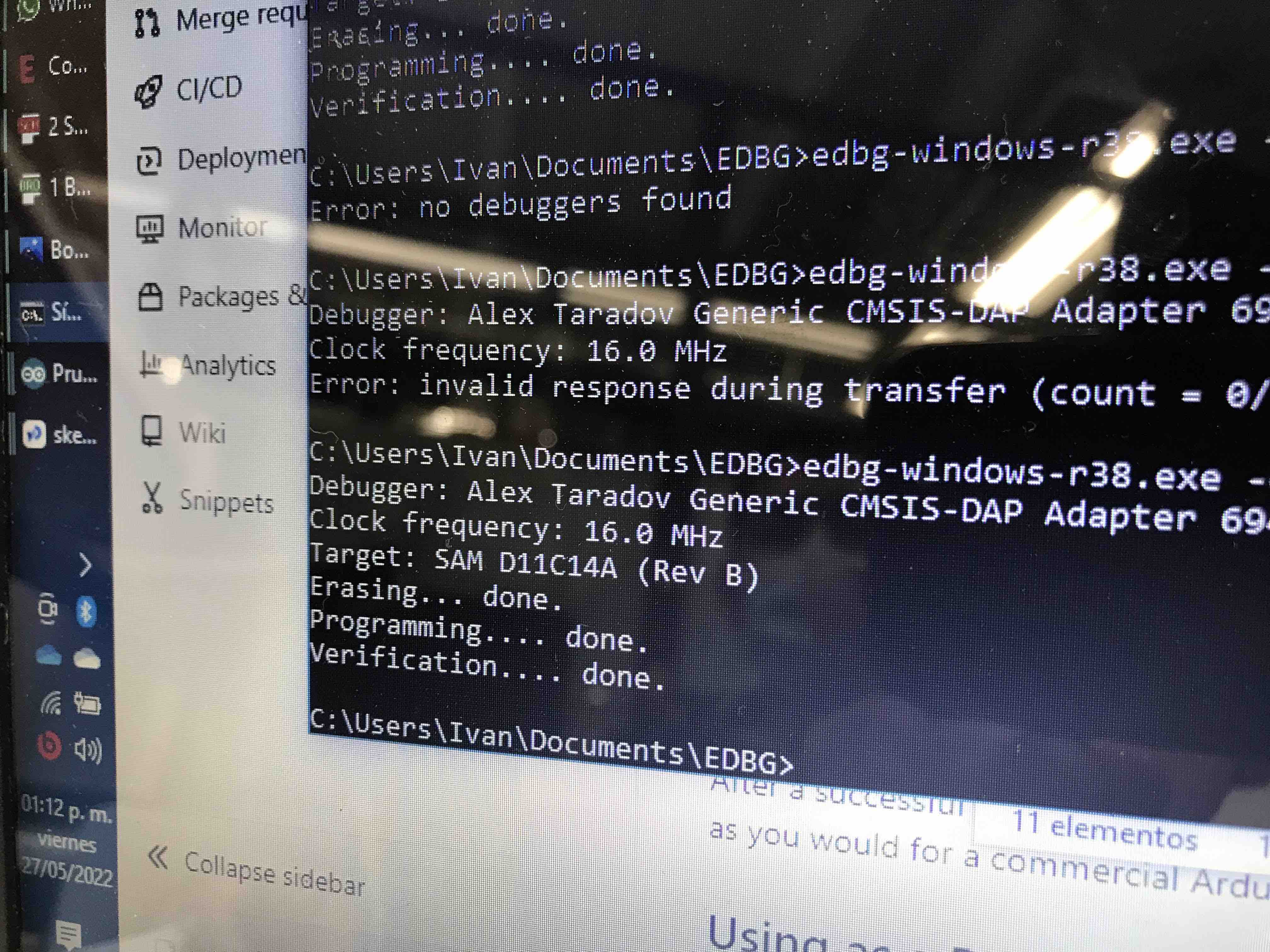
The verification was
succesfull
To test the Hugodino
heré the code I use to test it; make the LED blink and the servo to
rotate into different positions and reading both one after another
so the LED turn off then the servo moves, then the LED turns on and
the servo rotate, and so, goes on and on
LED in pin 2
Servo in pin 8
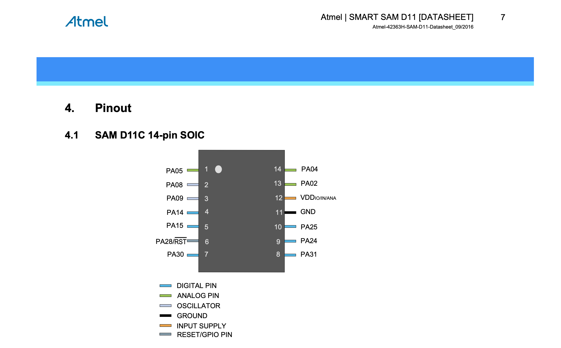
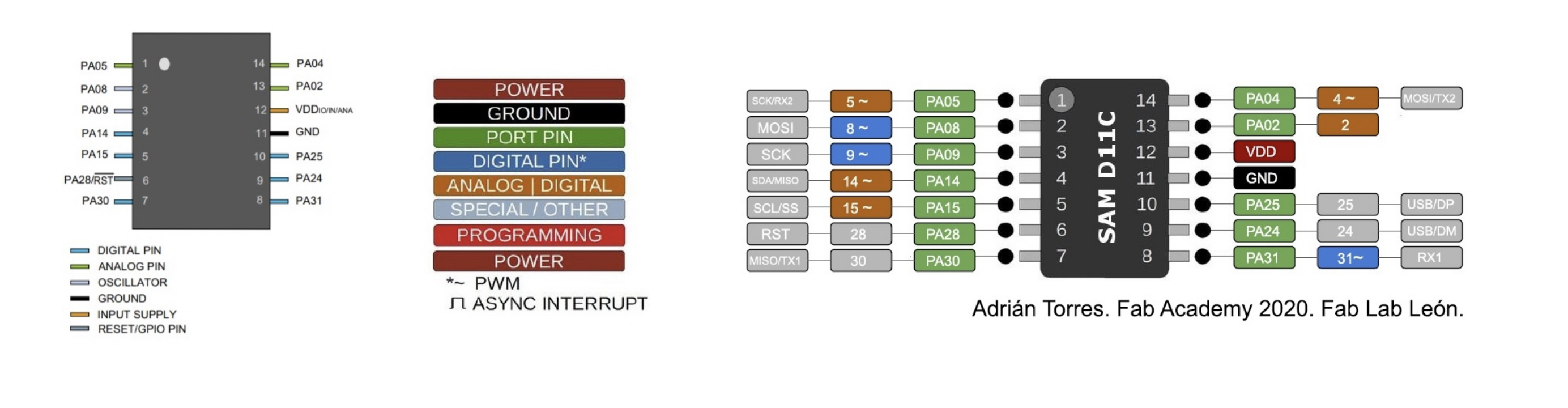
In the Data sheet we
can find wich pin is Digital, Analog, where is GND and VCC, this
information is very usefull to connect the sensors, leds and other
components for future projects, for example ; PINS
02,04,05,08,09,4,15 and 31 are the digital ones and PINS 02,04,05,14
and 15 can be configured as analogs.
To test the hugodino
I´m going to use a servo and blink the hugodino led.
In the code, the LED
blink and the servo to rotate into different positions alternating
one after another so the LED turn off then the servo moves, then the
LED turns on and the servo rotate, and so, the reading goes on and
on
Here is the code and a
video
int led = 2;
int servo = 8;
int angle;
int pwm;
void setup()
{
pinMode(servo, OUTPUT);
pinMode(led, OUTPUT);
}
void loop ()
{
digitalWrite(led,HIGH);
delay(1000);
servoPulse(servo, 15);
delay(1000);
digitalWrite(led,LOW);
delay(1000);
servoPulse(servo, 90);
delay(1000);
digitalWrite(led,HIGH);
delay(1000);
servoPulse(servo, 120);
delay(1000);
digitalWrite(led,LOW);
delay(1000);
servoPulse(servo, 180);
delay(1000);
}
void servoPulse (int servo, int angle)
{
pwm = (angle*11) + 500; // Convert angle to microseconds
digitalWrite(servo, HIGH);
delayMicroseconds(pwm);
digitalWrite(servo, LOW);
delay(50); // Refresh cycle of servo
}
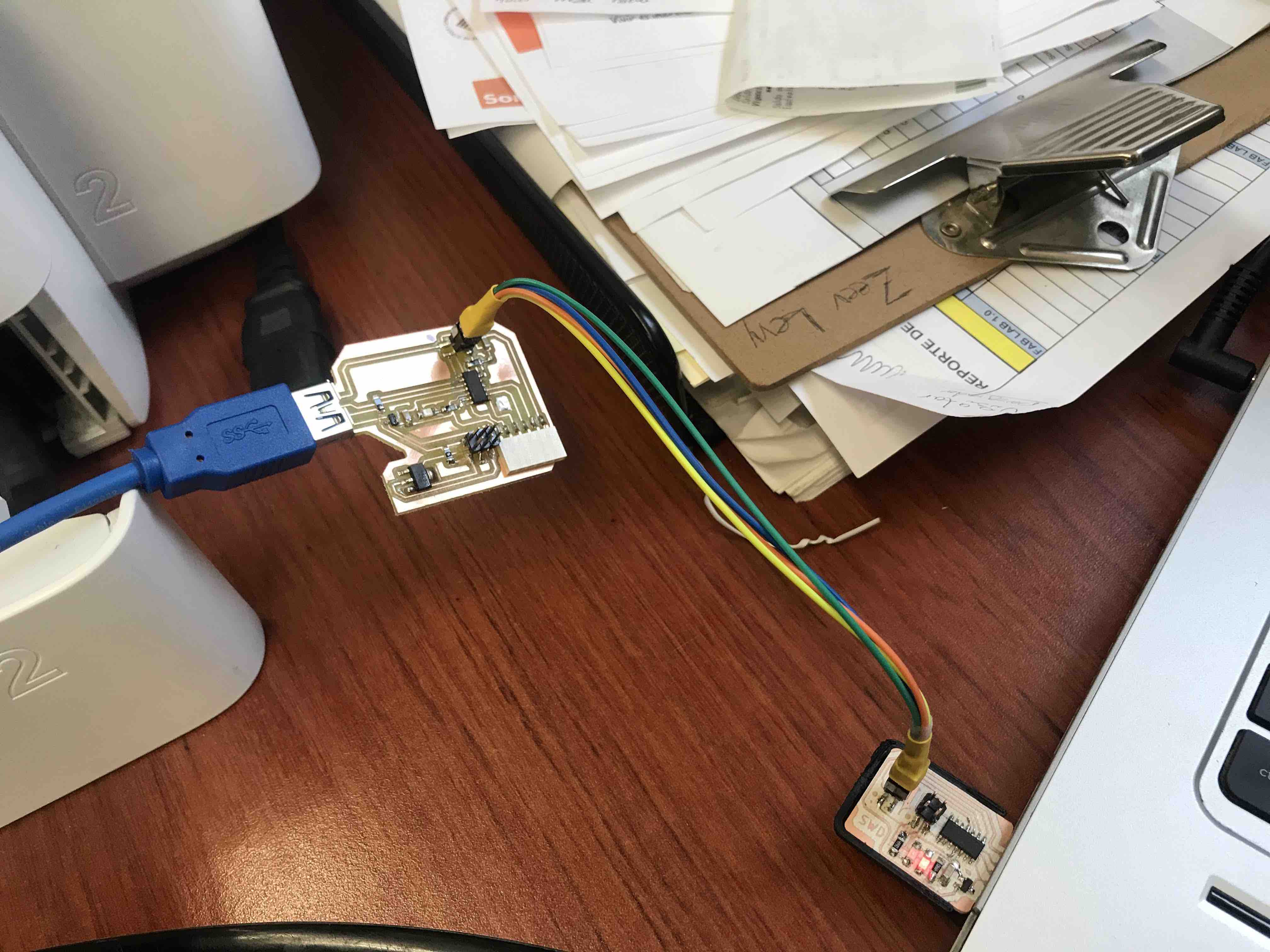
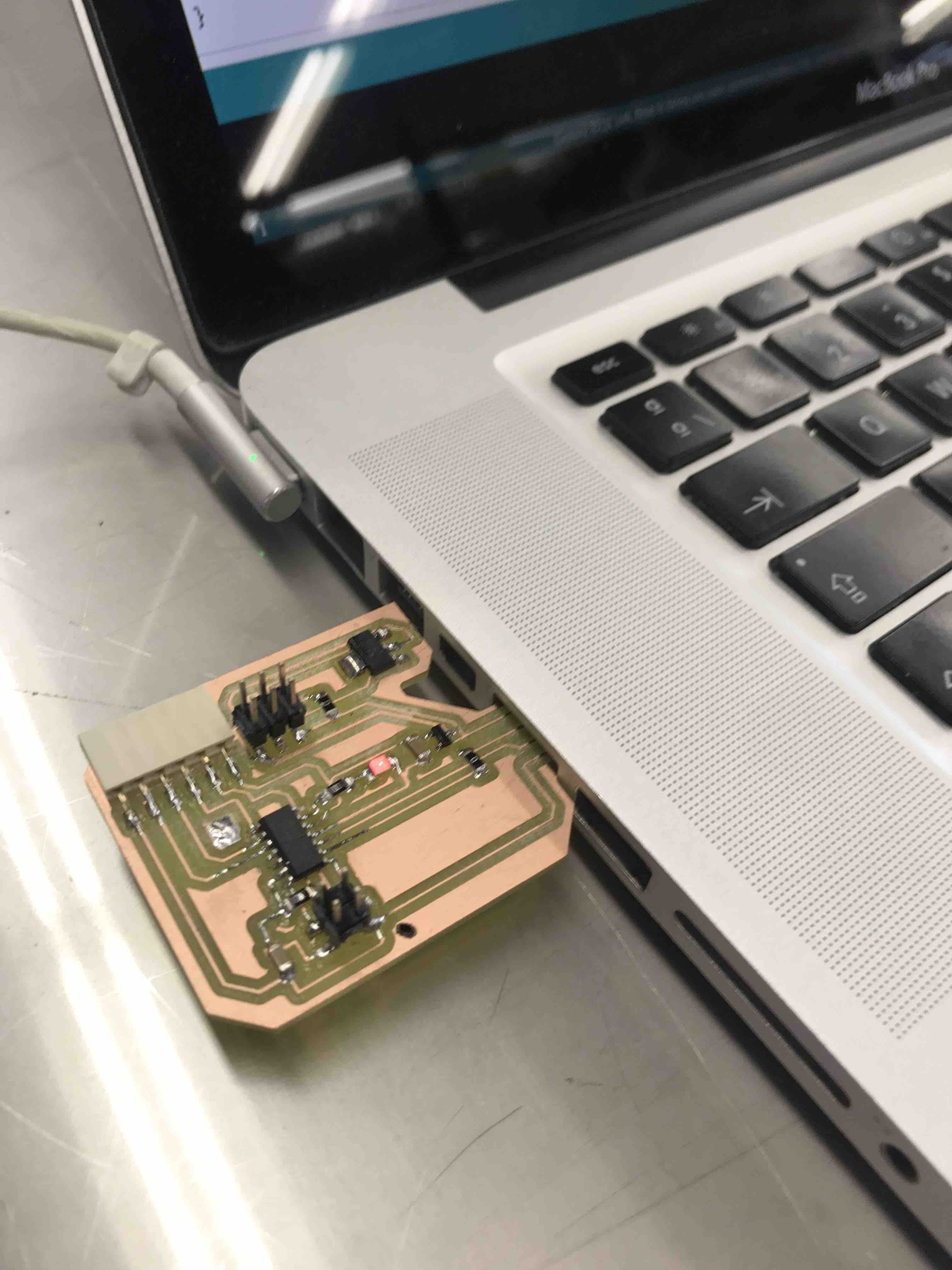
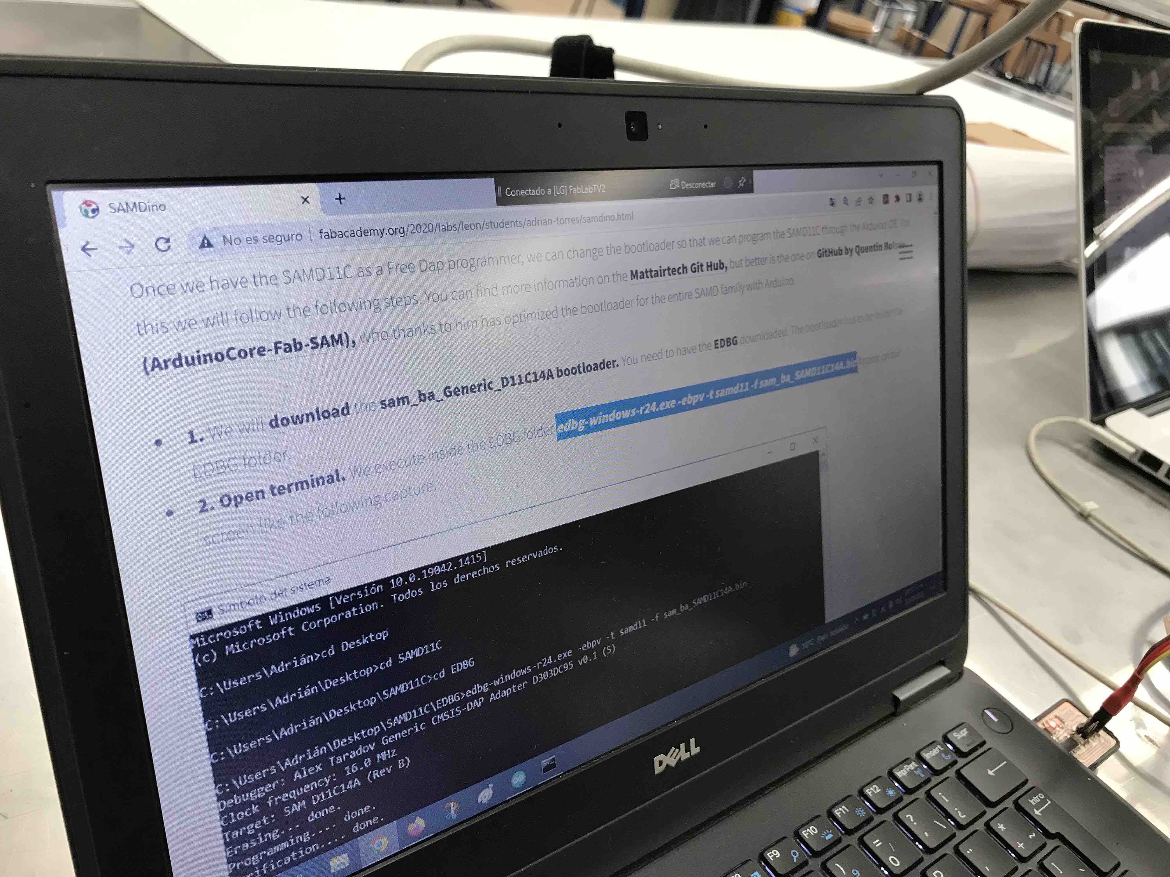
For this assignment I
design a new PCB with a LED and a button in eagle, then following the
steps that Adrian Torres mentioned in his web page link
to SAMDINO. I use the bootloader and execute
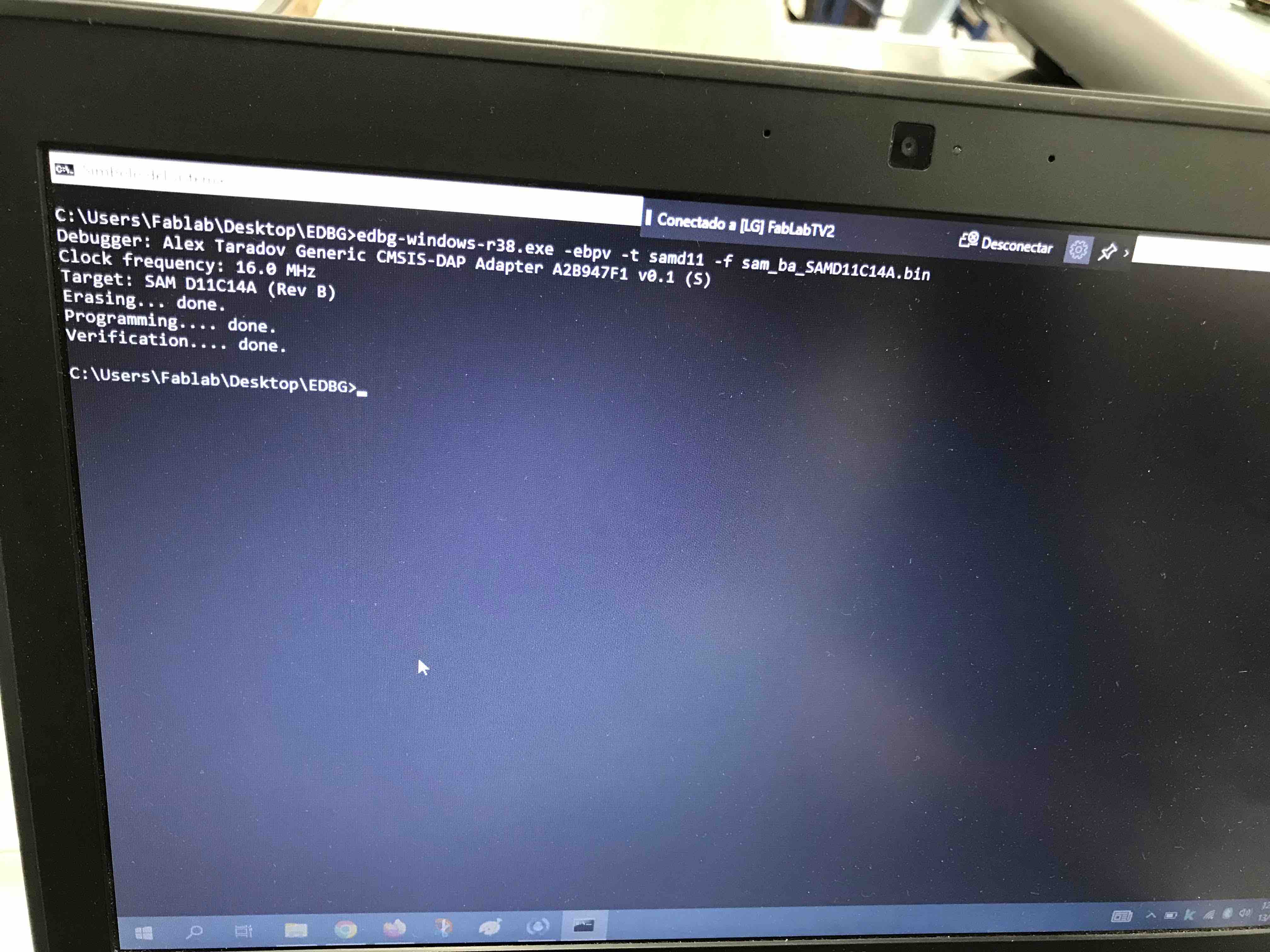
the EDBG
edbg-windows-r38.exe -ebpv -t samd11 -f sam_ba_SAMD11C14A.bin
and the verification was OK and the LED of my PCB turn ON.
edbg-windows-r38.exe -ebpv -t samd11 -f sam_ba_SAMD11C14A.bin
and the verification was OK and the LED of my PCB turn ON.
Then the code, I wanted
to blink the led with the button in two steps, when I push the button
for the first time I want the LED to blink with a delay of 1sec.
then, when I push the button for the second time I want theLED to
blink with a different delay, I decide that the delay now was of half
a second, with this two delays the difference of the blink speed will
become evident.
DATA SHEET:
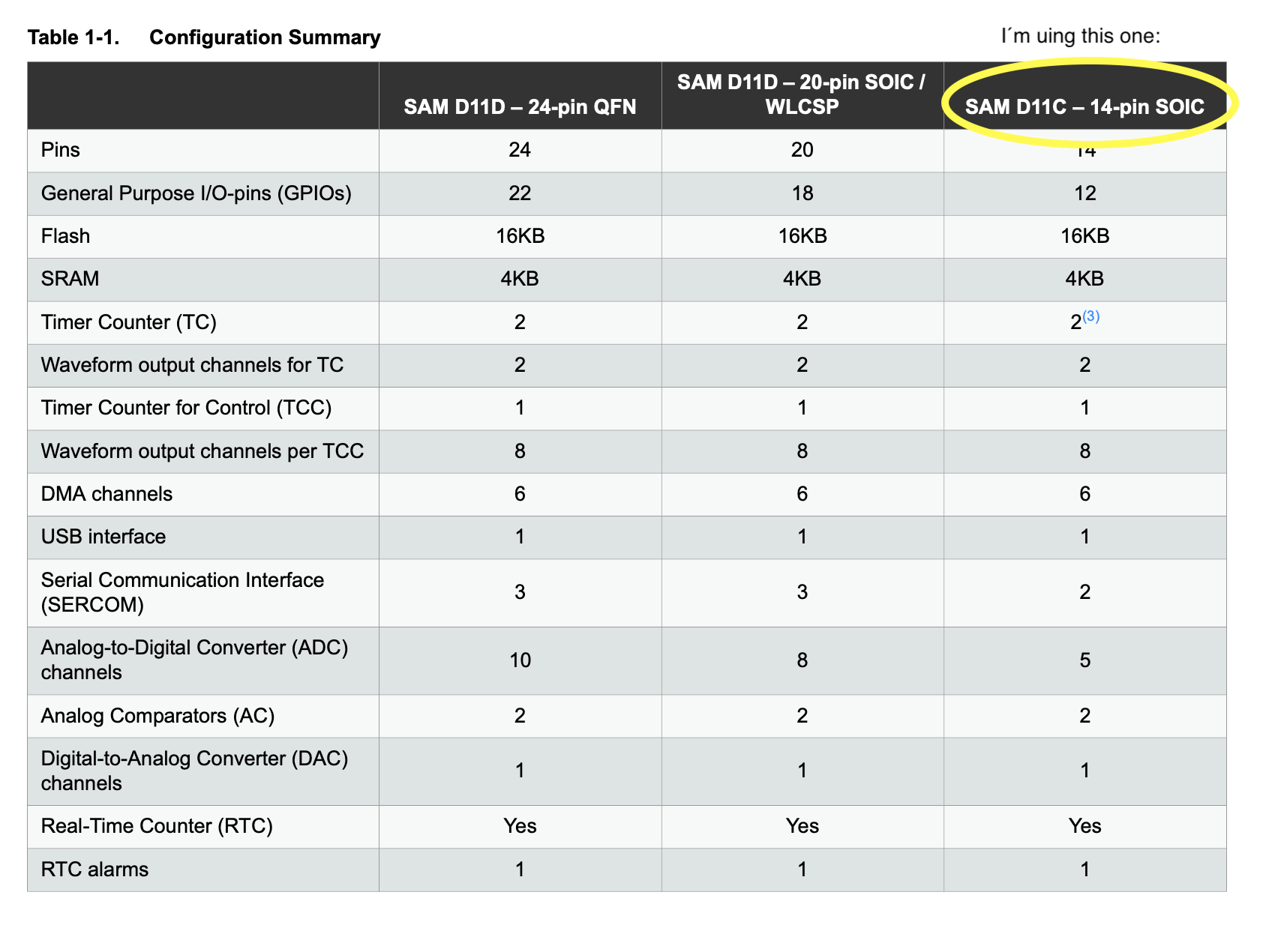
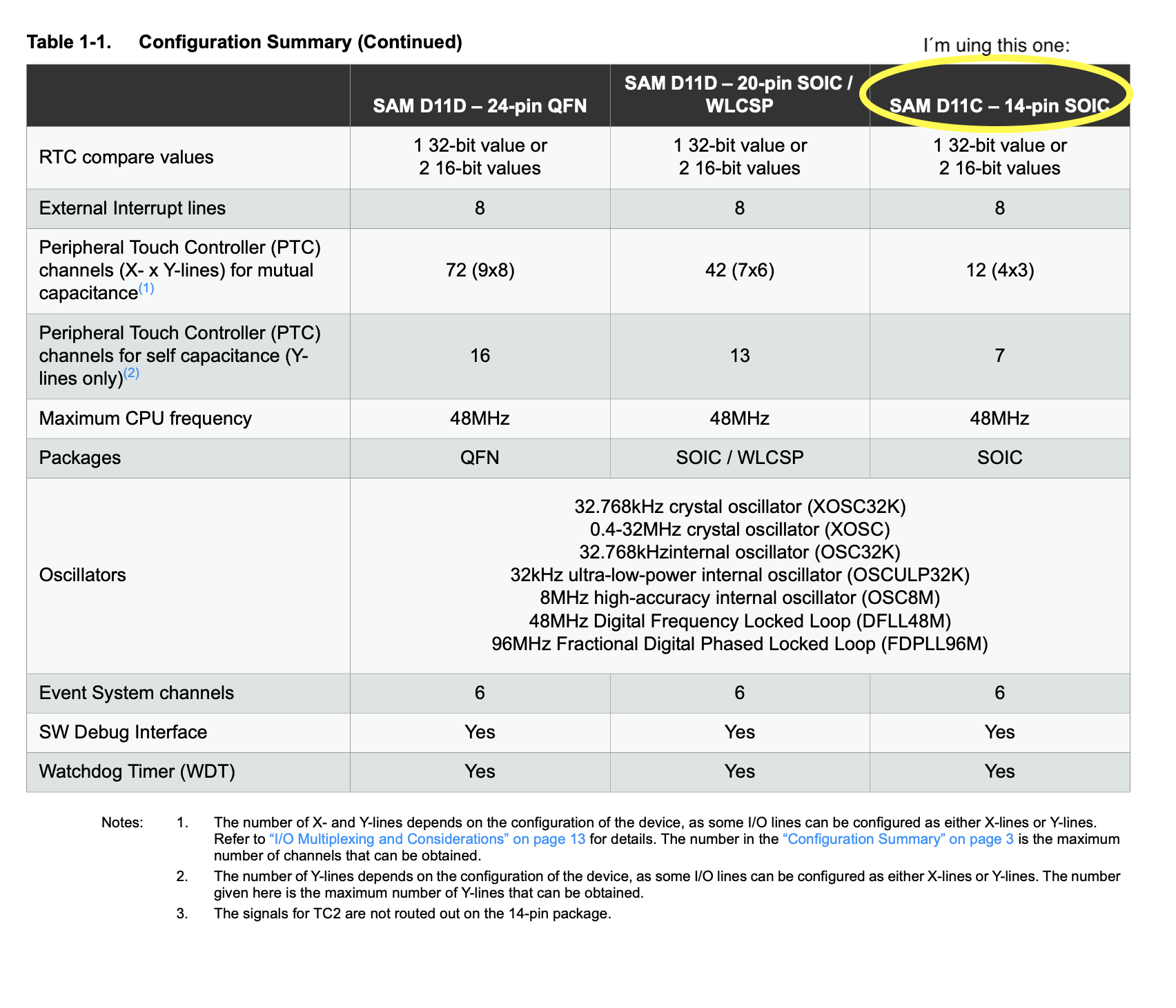
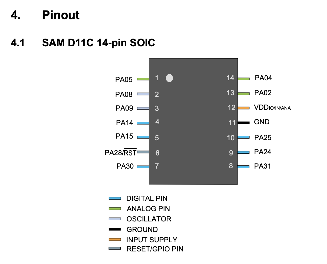
Reviewing the data sheet
we can find some important information about the SAMD11C:
-it has 14 PIN
-16KB flash
memory
-4KB SRAM
-Voltage Minimum 1.62V
Maximum 3.63V
-Digital pins :
PA02, PA04, PA05, PA08, PA09, PA14, PA15, PA31
(shown in green in the
image above, this are the ones where you are going to connect
the components of your board, example: if your are going to connect
your LED to the pin 2 or 4 that means thar you are going to connect
them in PA04 or in PA02 (PIN 14 or 13 shown inside the
microcontroller) and VDD and GND are connected to PINS 12 and 11.)
-Digital pins :
PA02, PA04, PA05, PA08, PA09, PA14 and PA15
(shown
in brown color in the image above)
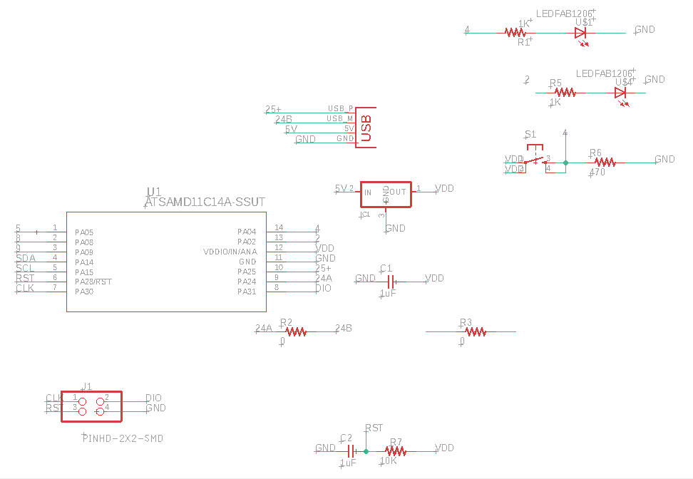
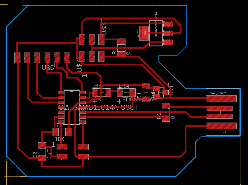
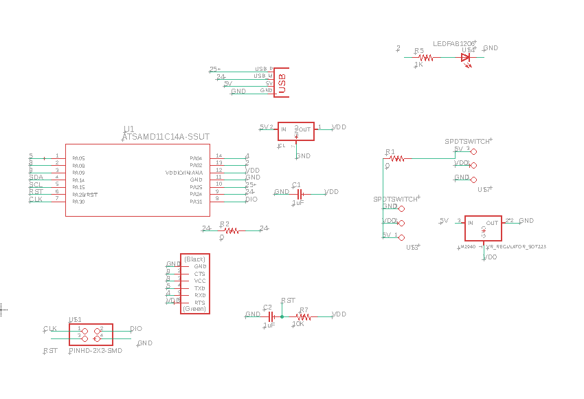
When designing the board
with the LED and the button I connect the LED to PIN02 and the button
to PIN04. Here the Schematic and Board images of my design
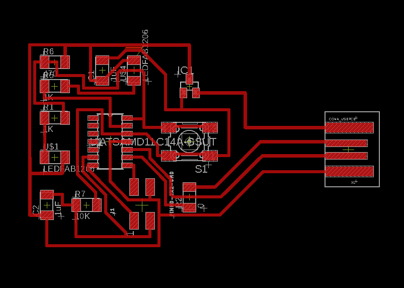
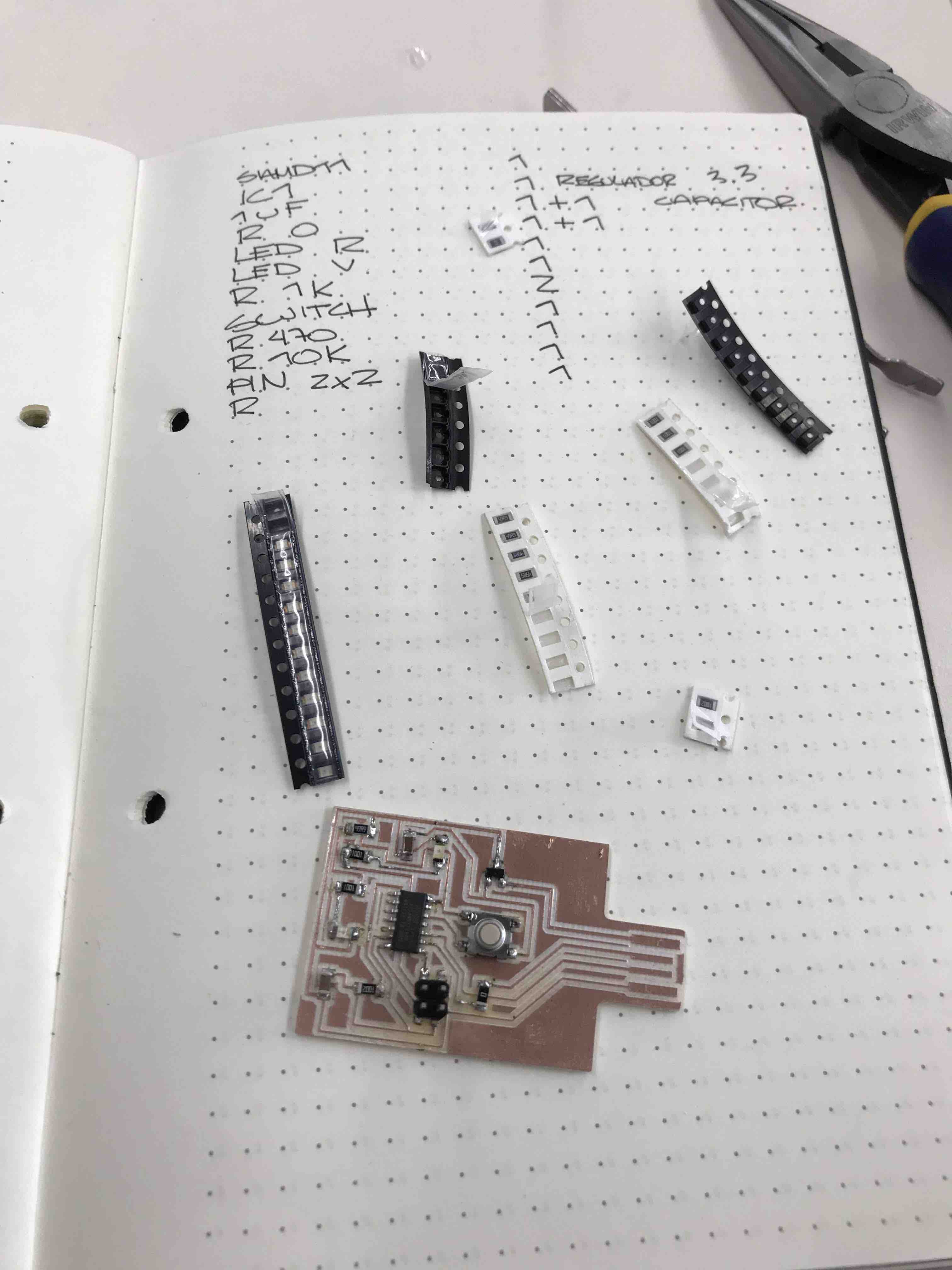
This is the list of the
components to weld in my PCB, Resistors, LED, Button, microcontroller,
PIN 2x2, regulator and capacitor.
Following the steps that
Adrián Torres mentioned in his webpage to download the bootloader and
for execute the EDBG.
The verification was
succesfull.
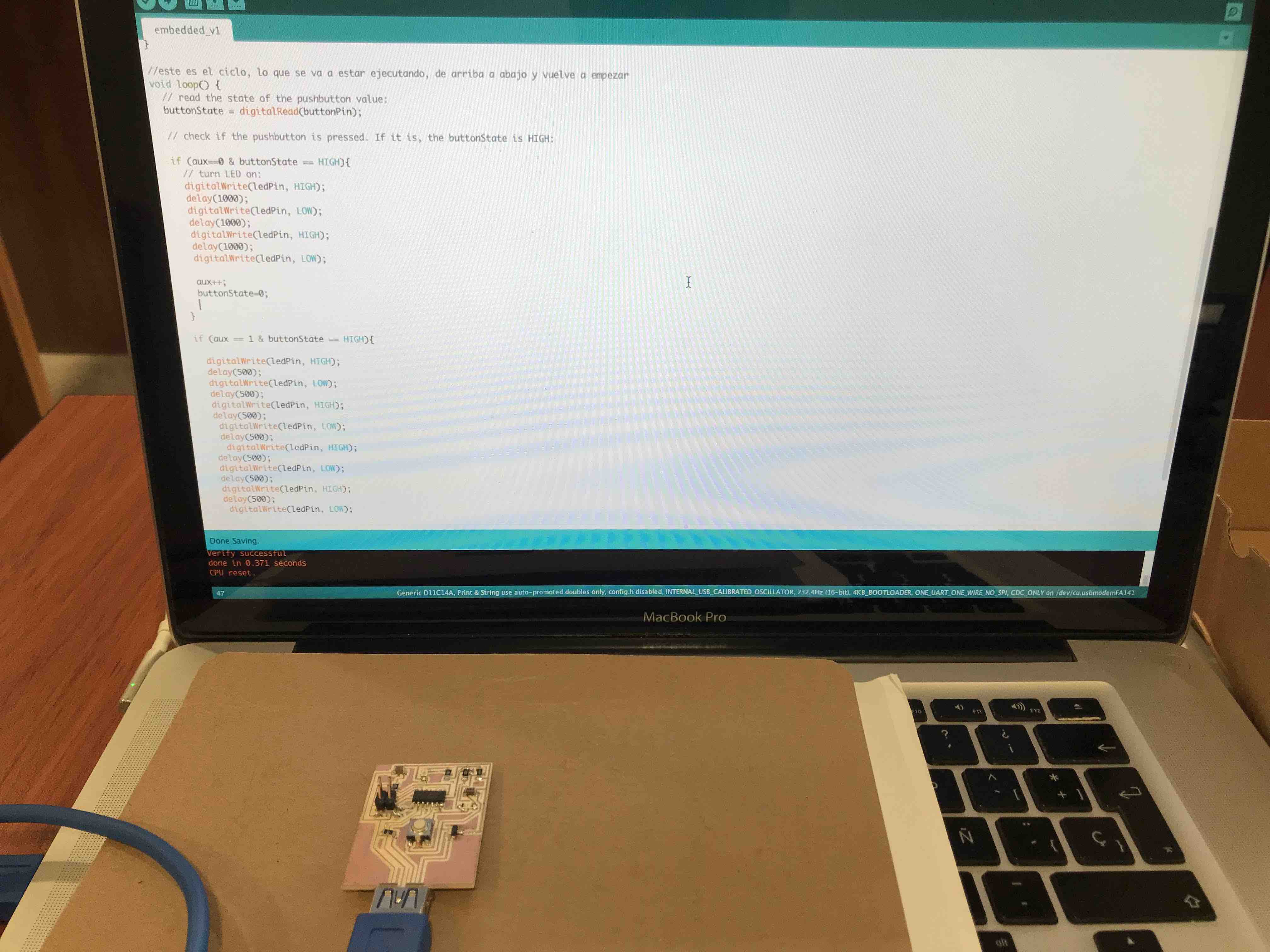
Then the code using a
button to blink the led.
there is a combination of
"States" between the button and the led, when the button is pressed
the state is HIGH, and when the LED is ON his state is ON, so with
this in mind the code will tell the LED wehn to turn ON and start to
Blink, and then adding the "int aux" we can push the button once and
the LED will blink with a delay of 1sec. and if we push the button for
the second time the LED will blink with a delay of half a second.
Here is the code:
/*
created 2005
by DojoDave <http://www.0j0.org>
modified 30 Aug 2011
by Tom Igoe
*/
// constants won't change. They're used here to set pin numbers:
const int buttonPin = 4; // the number of the pushbutton pin
const int ledPin = 2; // the number of the LED pin
int aux=0;
// variables will change:
int buttonState = 0; // variable for reading the pushbutton status
//aqui voy a indicar que es salida o entrada por ejemplo: Servo, LDR, LED INPUT o OUTPUT
void setup() {
// initialize the LED pin as an output:
pinMode(ledPin, OUTPUT);
// initialize the pushbutton pin as an input:
pinMode(buttonPin, INPUT);
}
//este es el ciclo, lo que se va a estar ejecutando, de arriba a abajo y vuelve a empezar
void loop() {
// read the state of the pushbutton value:
buttonState = digitalRead(buttonPin);
// check if the pushbutton is pressed. If it is, the buttonState is HIGH:
if (aux==0 & buttonState == HIGH){
// turn LED on:
digitalWrite(ledPin, HIGH);
delay(1000);
digitalWrite(ledPin, LOW);
delay(1000);
digitalWrite(ledPin, HIGH);
delay(1000);
digitalWrite(ledPin, LOW);
aux++;
buttonState=0;
}
if (aux == 1 & buttonState == HIGH){
digitalWrite(ledPin, HIGH);
delay(500);
digitalWrite(ledPin, LOW);
delay(500);
digitalWrite(ledPin, HIGH);
delay(500);
digitalWrite(ledPin, LOW);
delay(500);
digitalWrite(ledPin, HIGH);
delay(500);
digitalWrite(ledPin, LOW);
delay(500);
digitalWrite(ledPin, HIGH);
delay(500);
digitalWrite(ledPin, LOW);
aux=0;
}
else {
// turn LED off:
digitalWrite(ledPin, LOW);
}
}
In this video we can see
the LED blink ON and OFF in different speed dependind if we push the
button for the first time or twice.