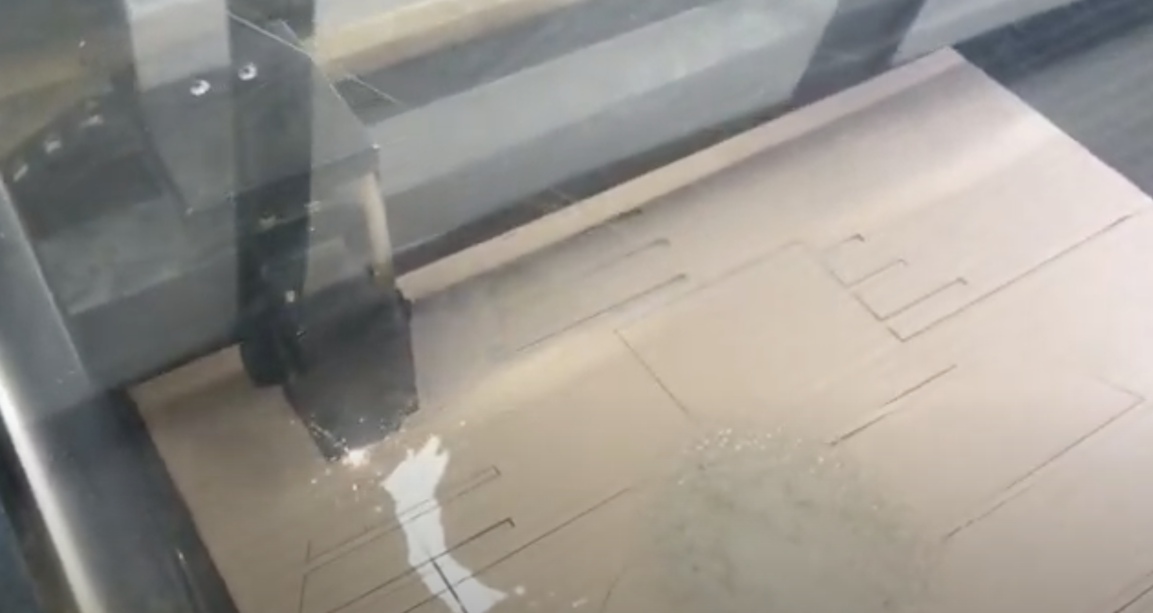
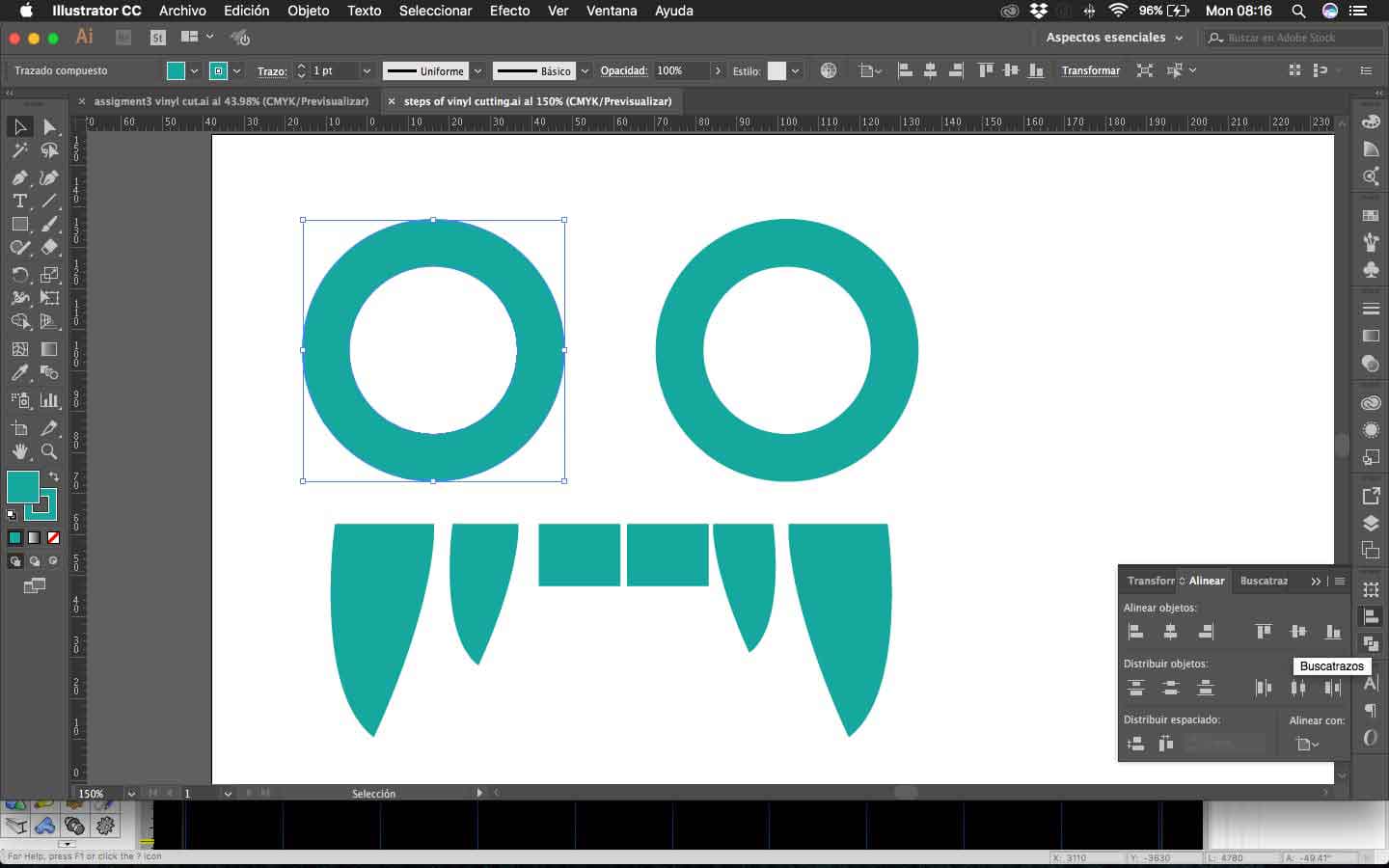
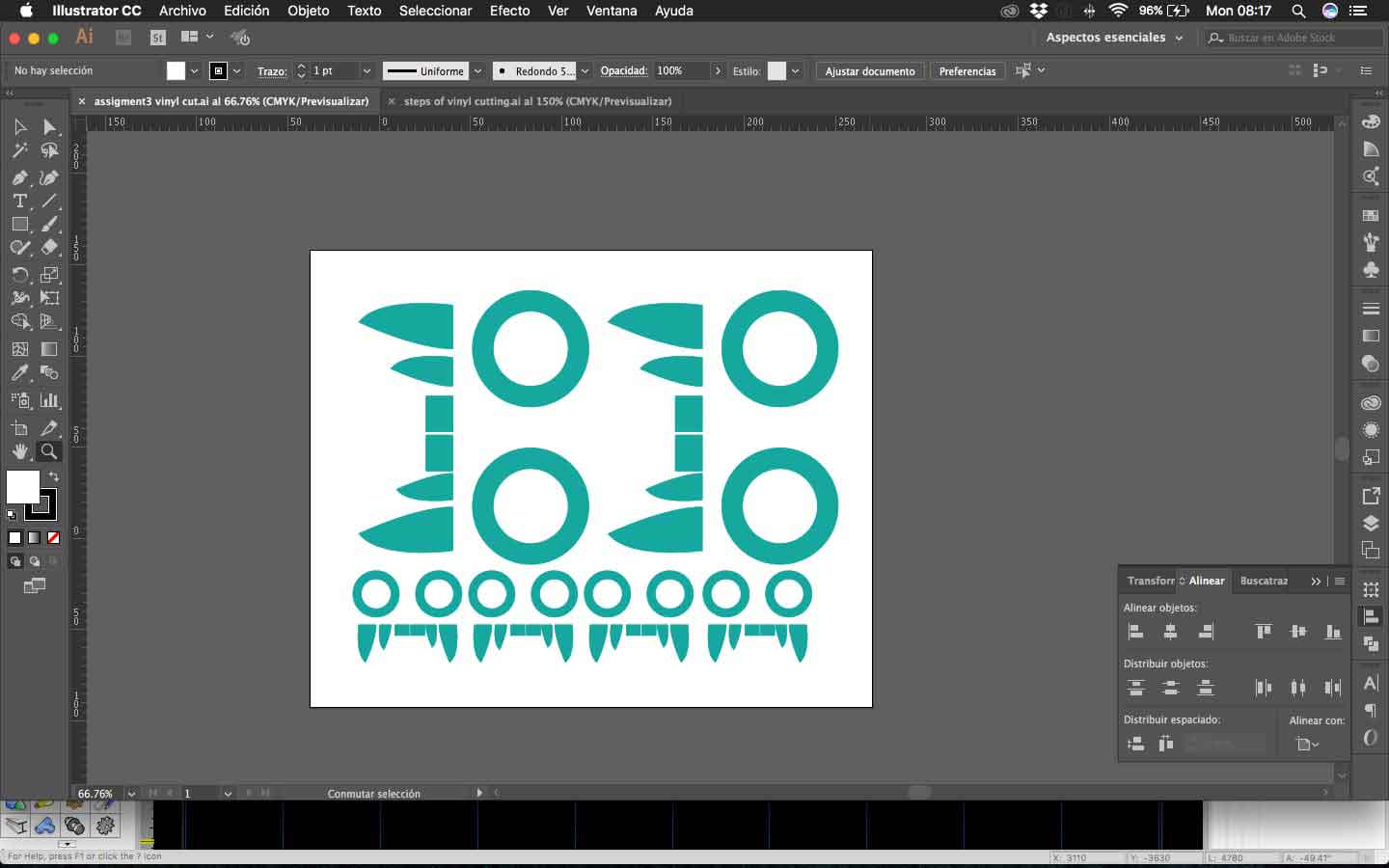
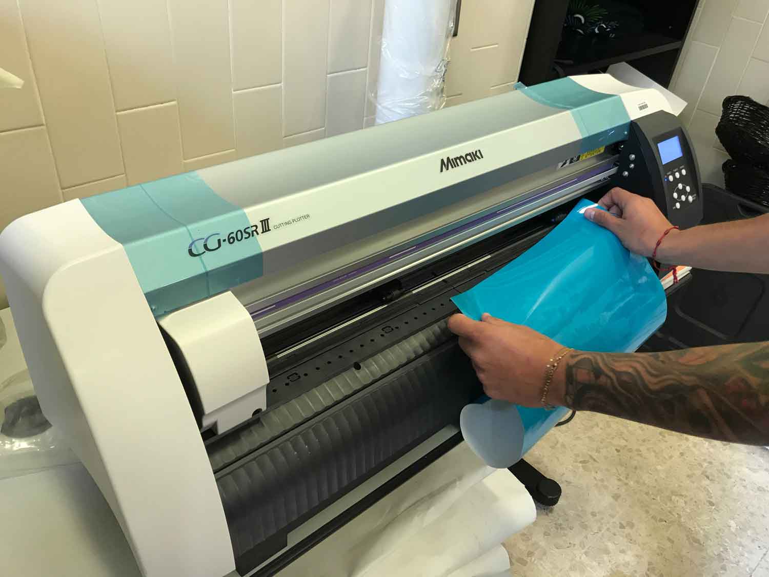
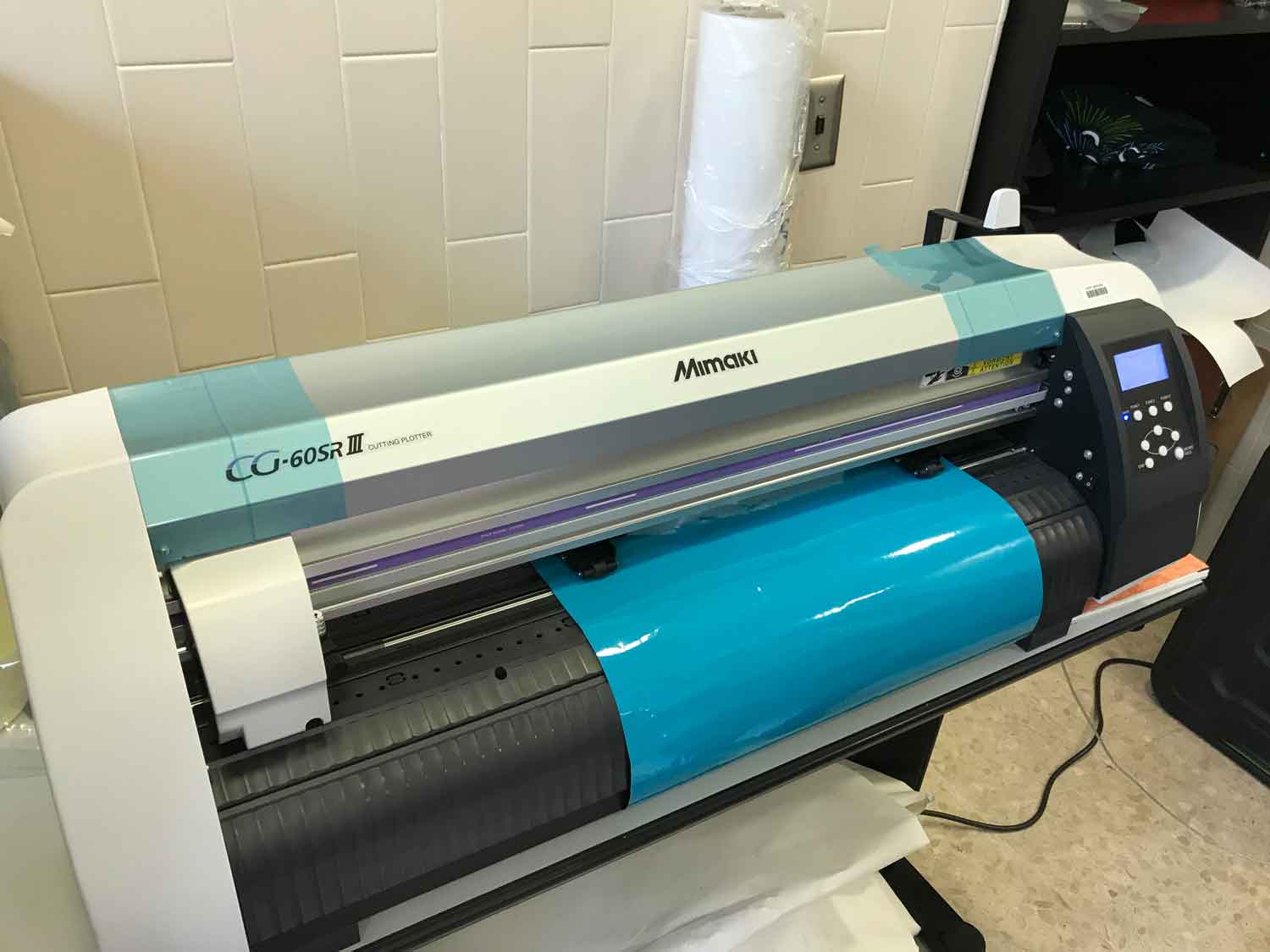
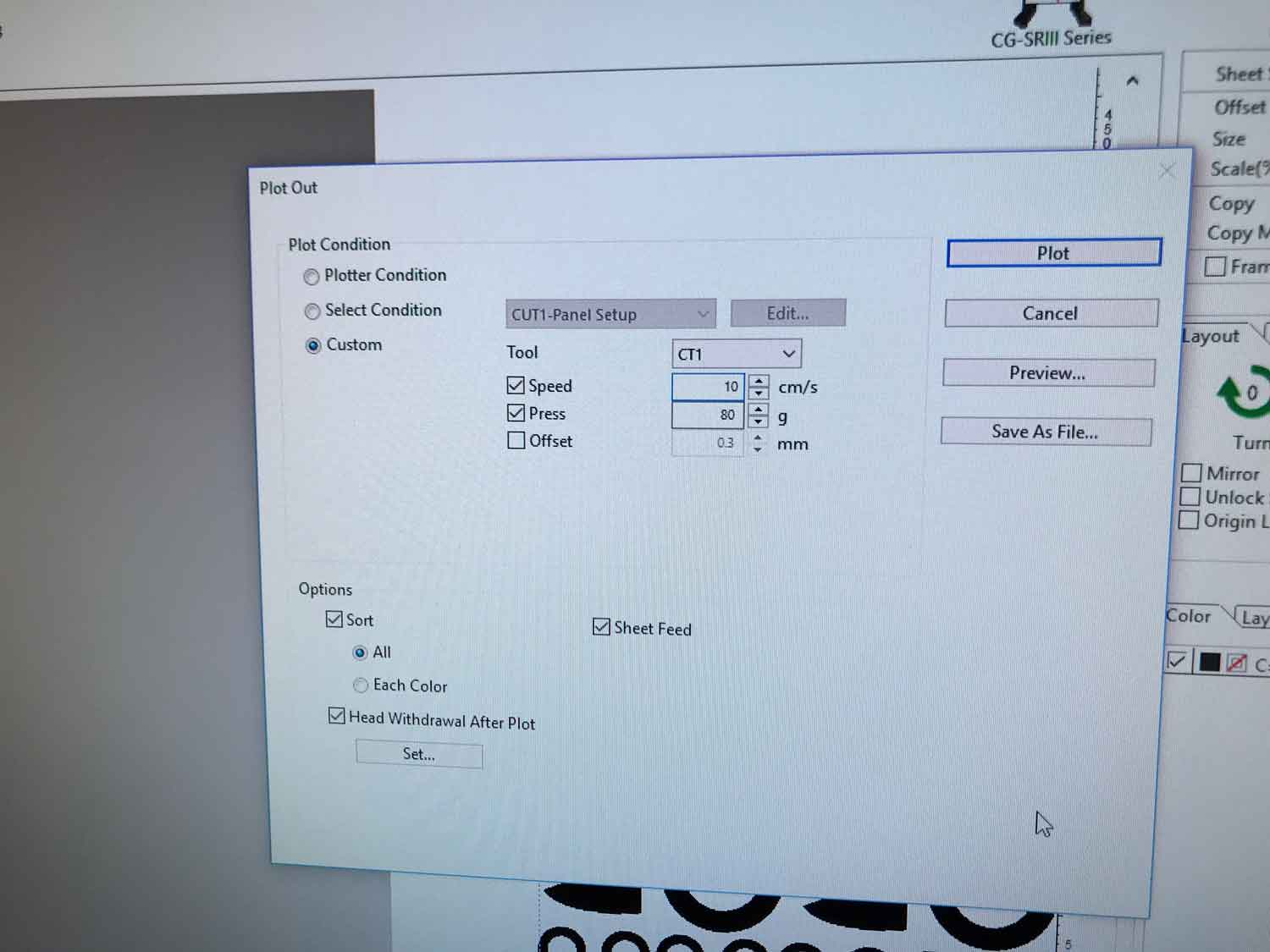
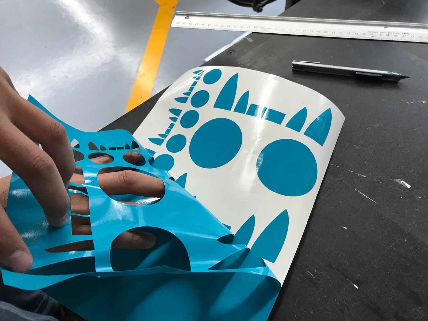
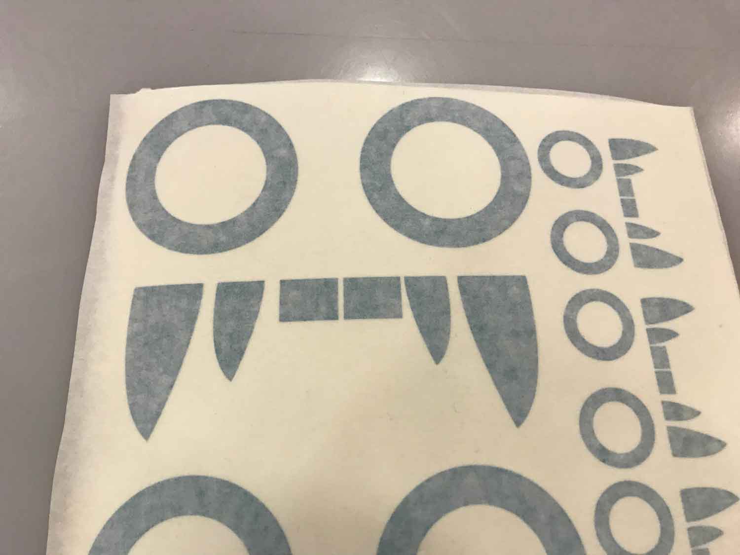
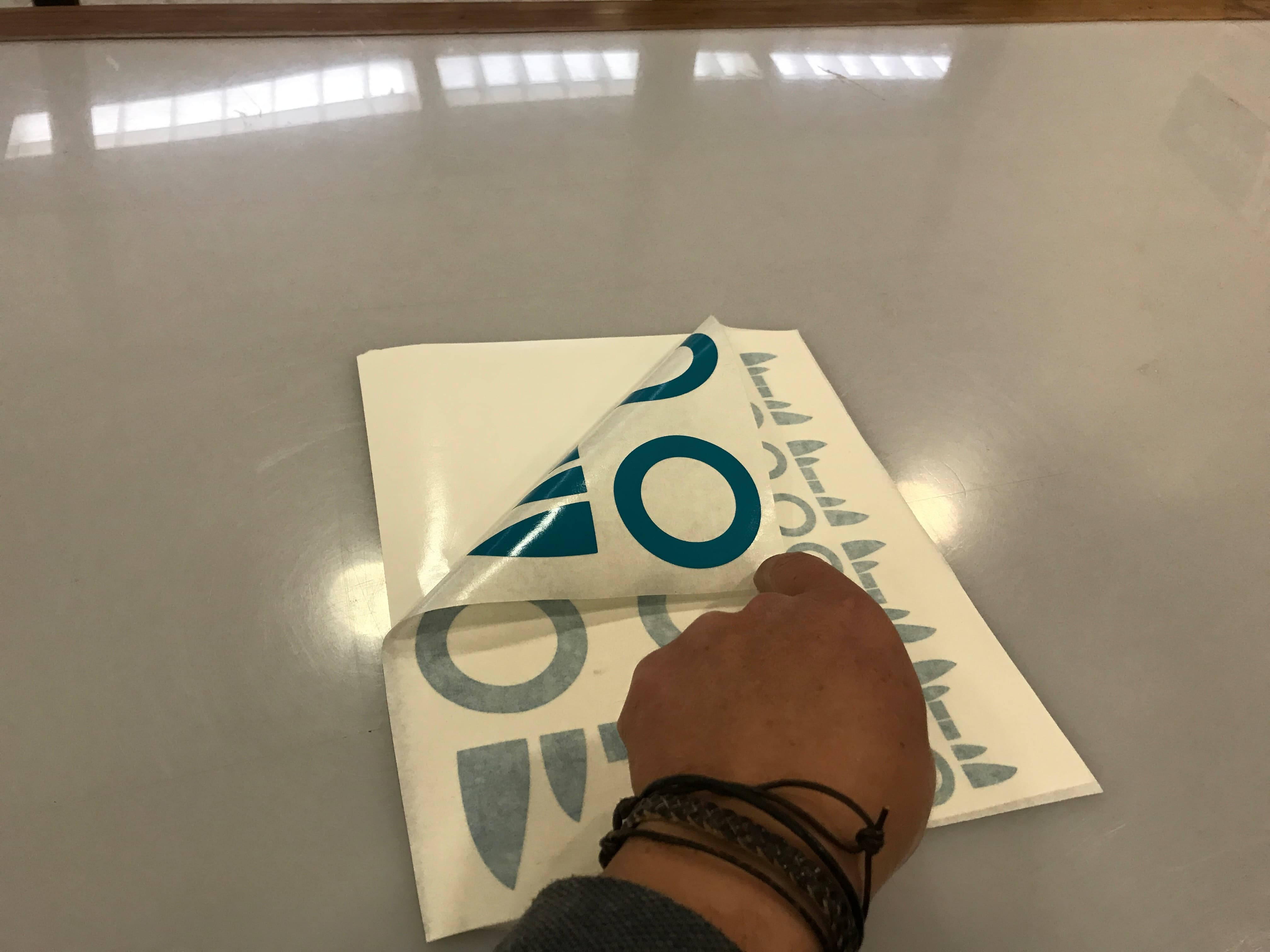
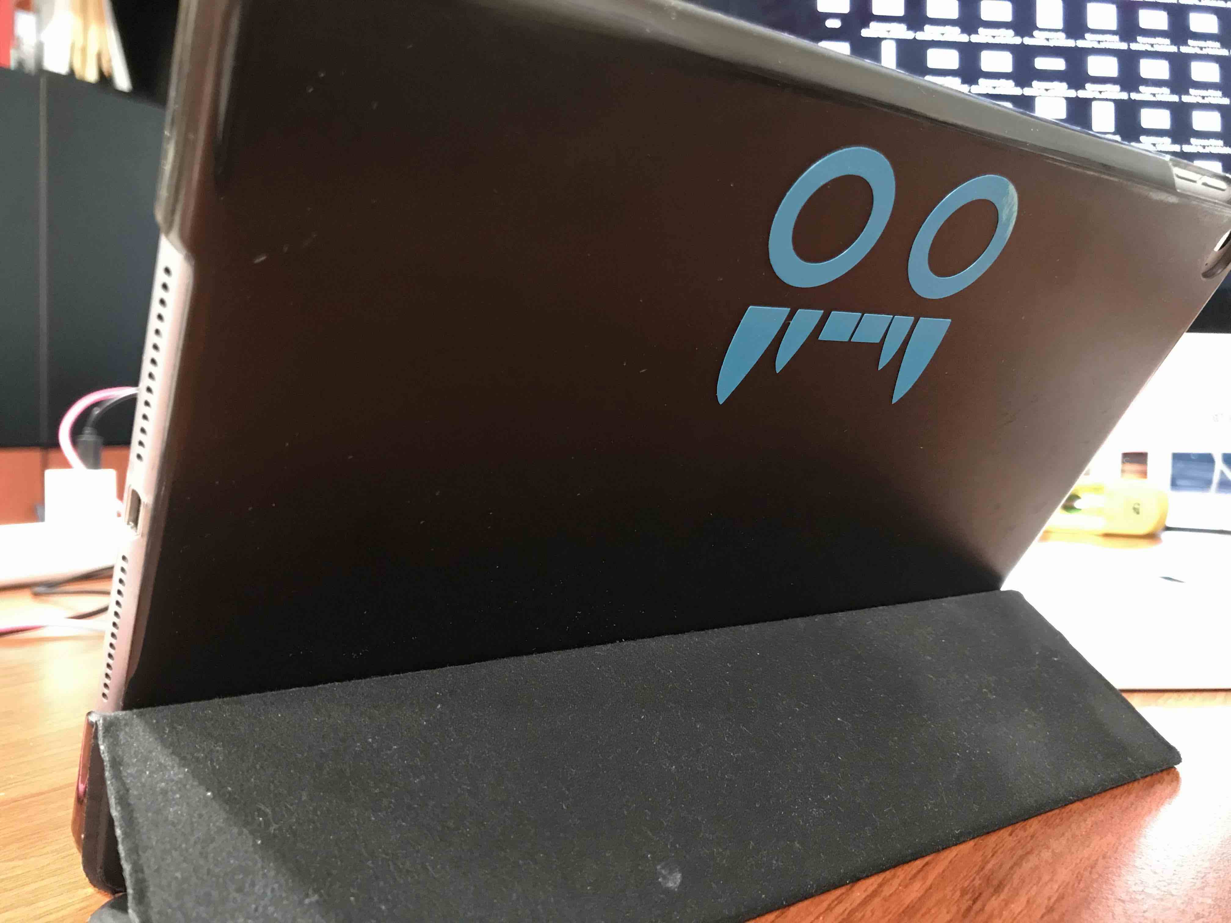
computer-controlled cutting
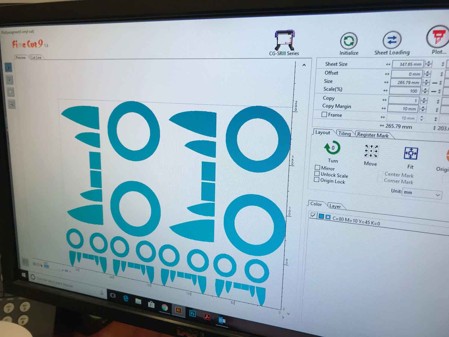
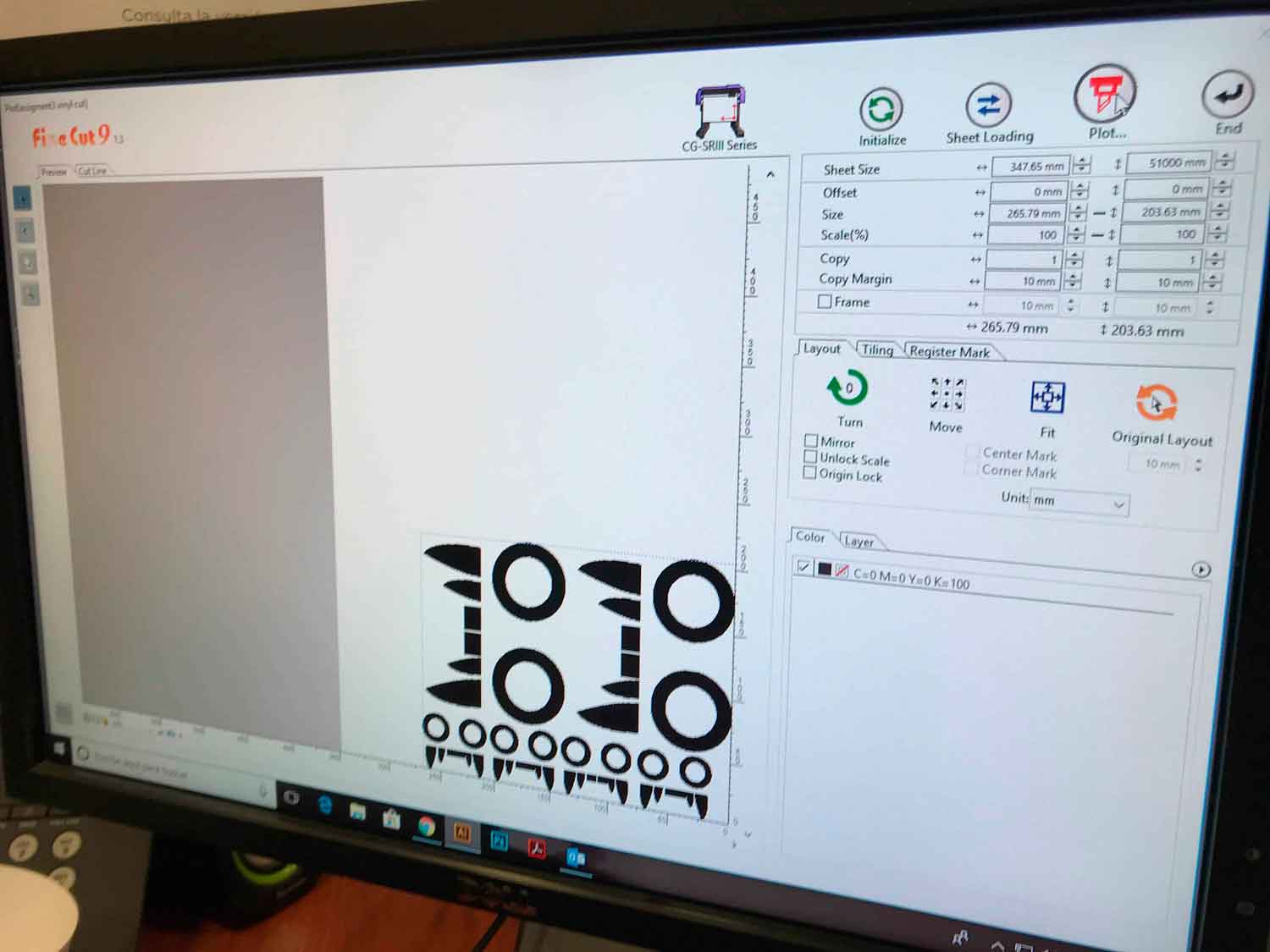
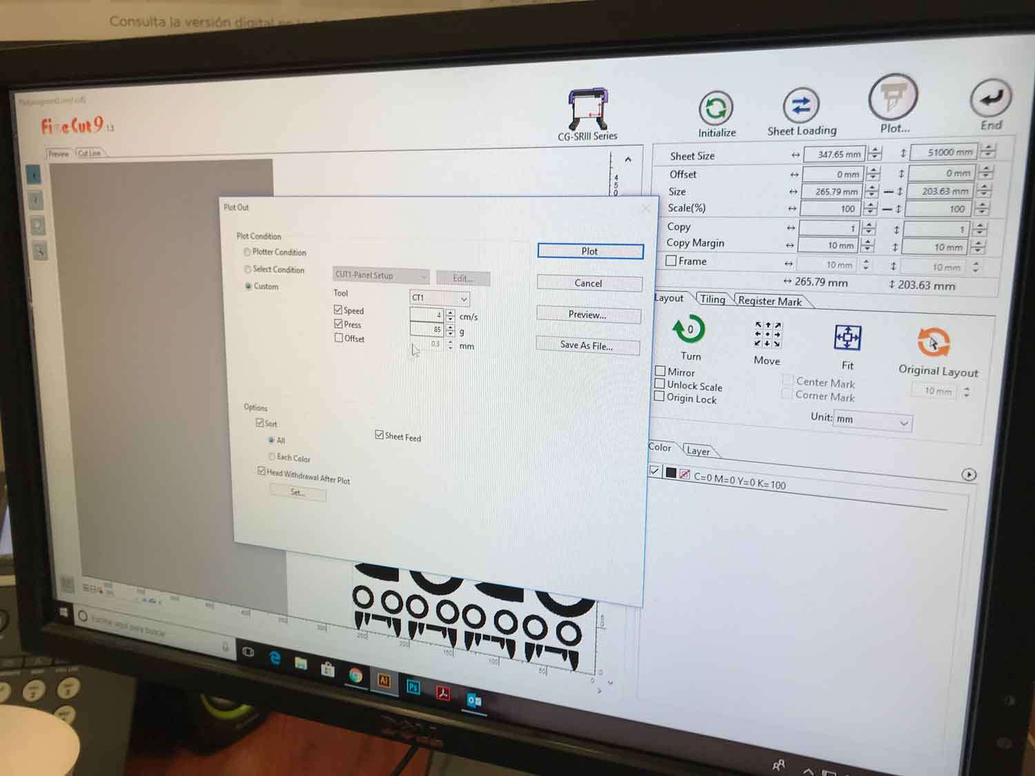
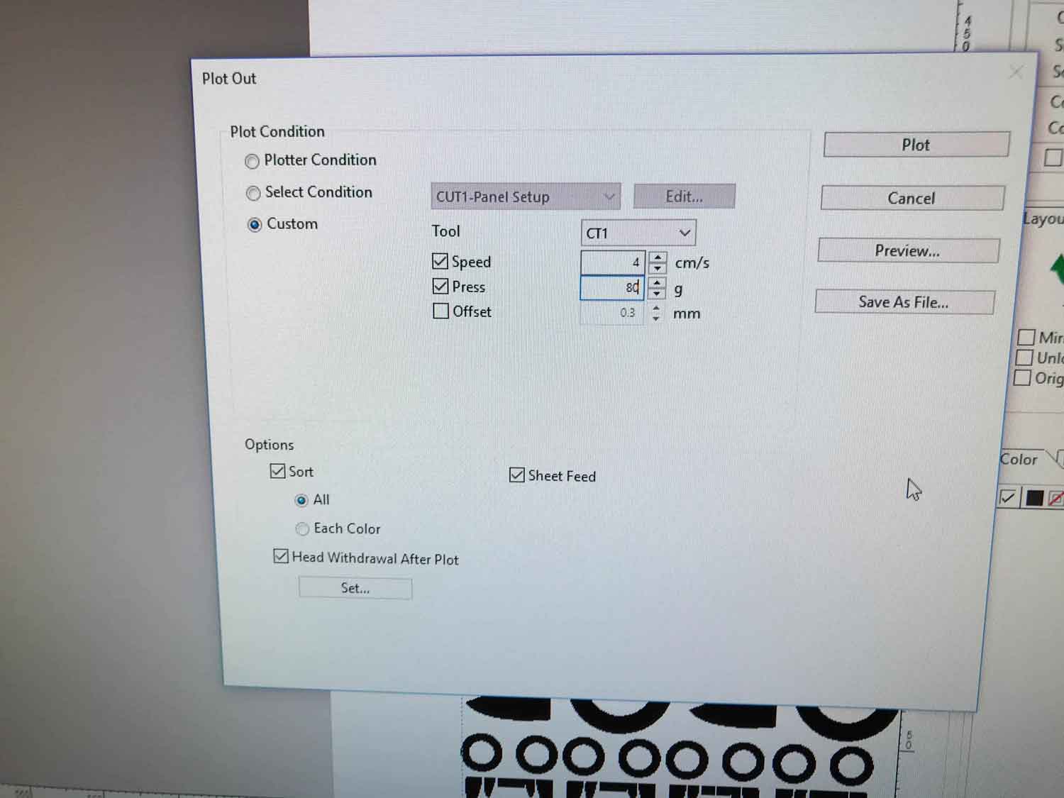
cut something in the vinylcutter
.
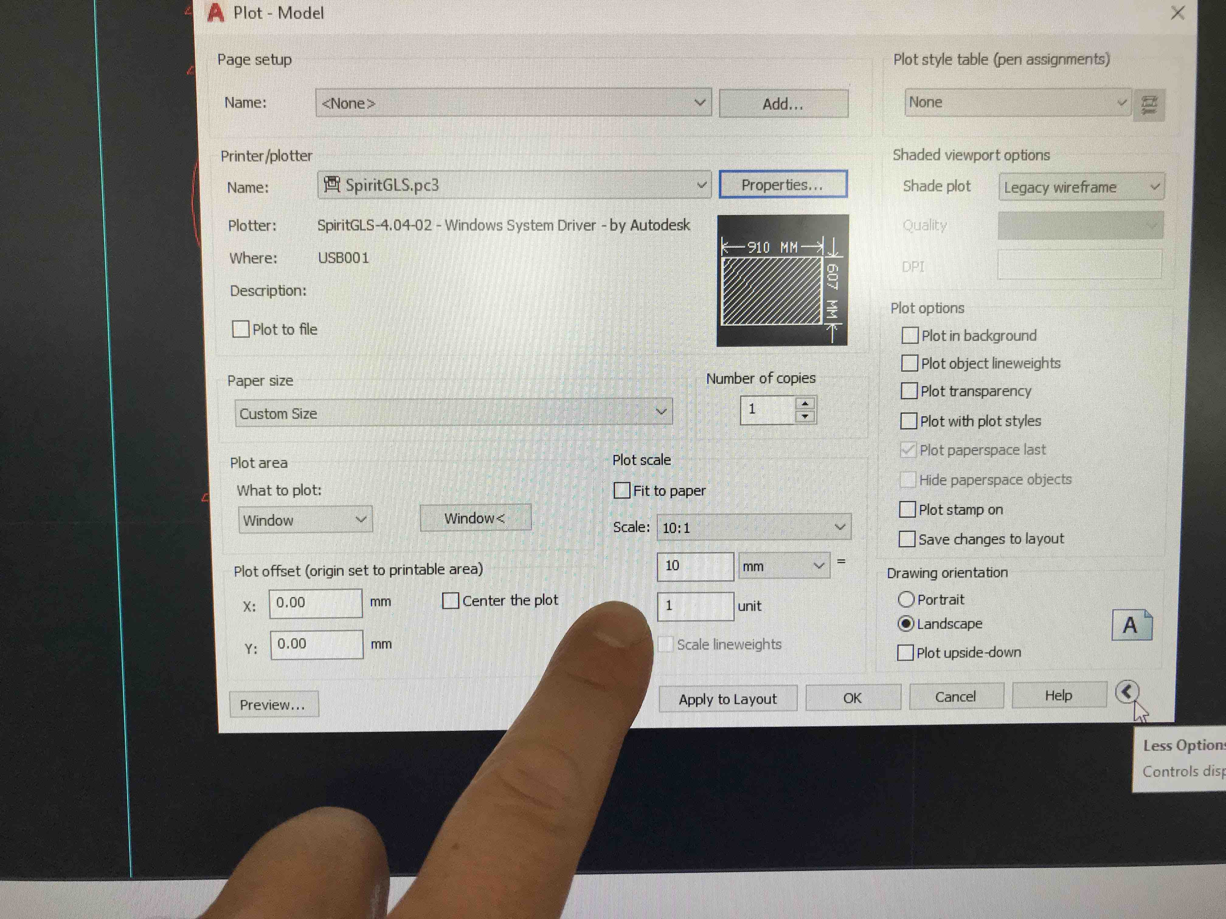
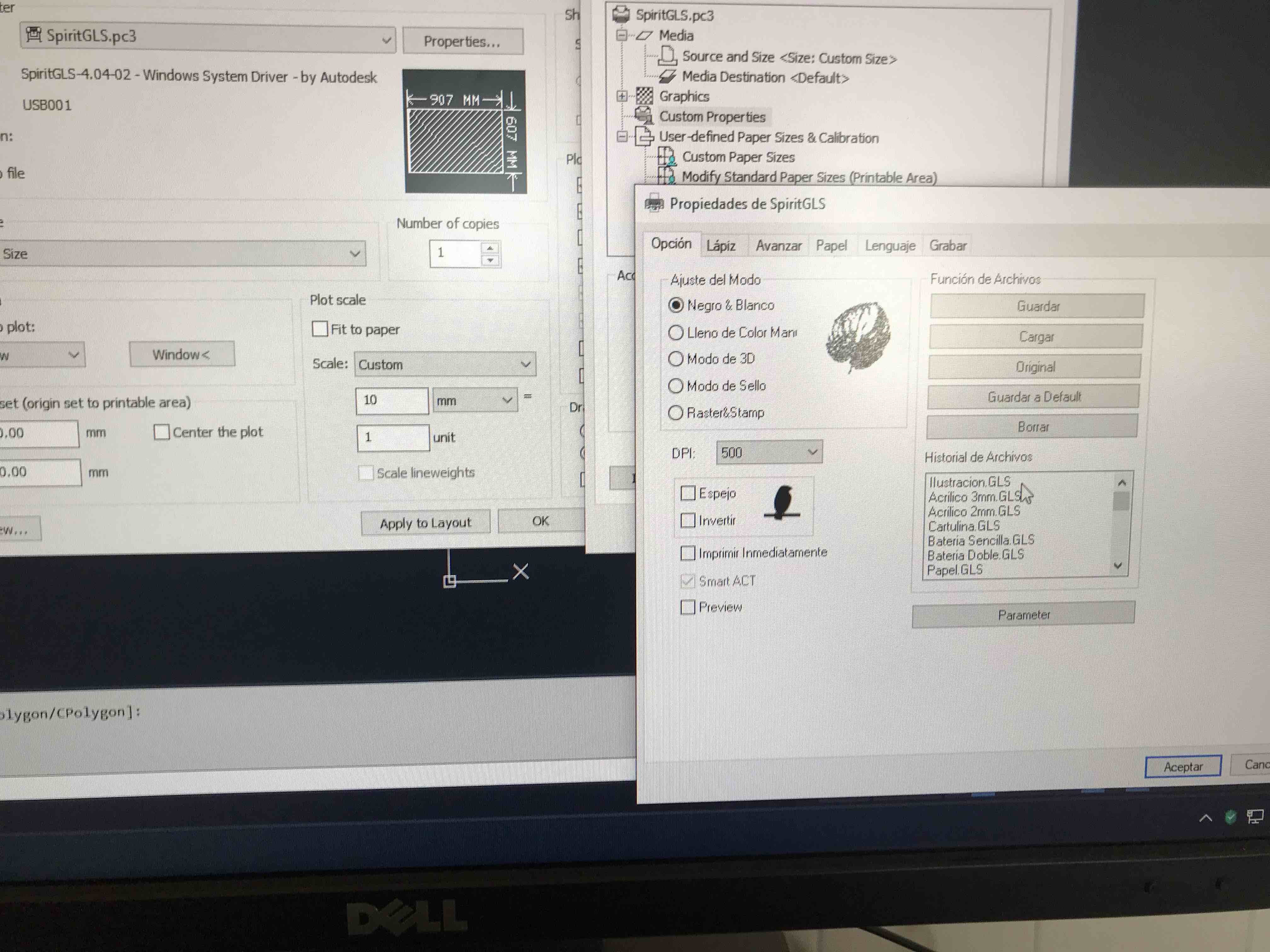
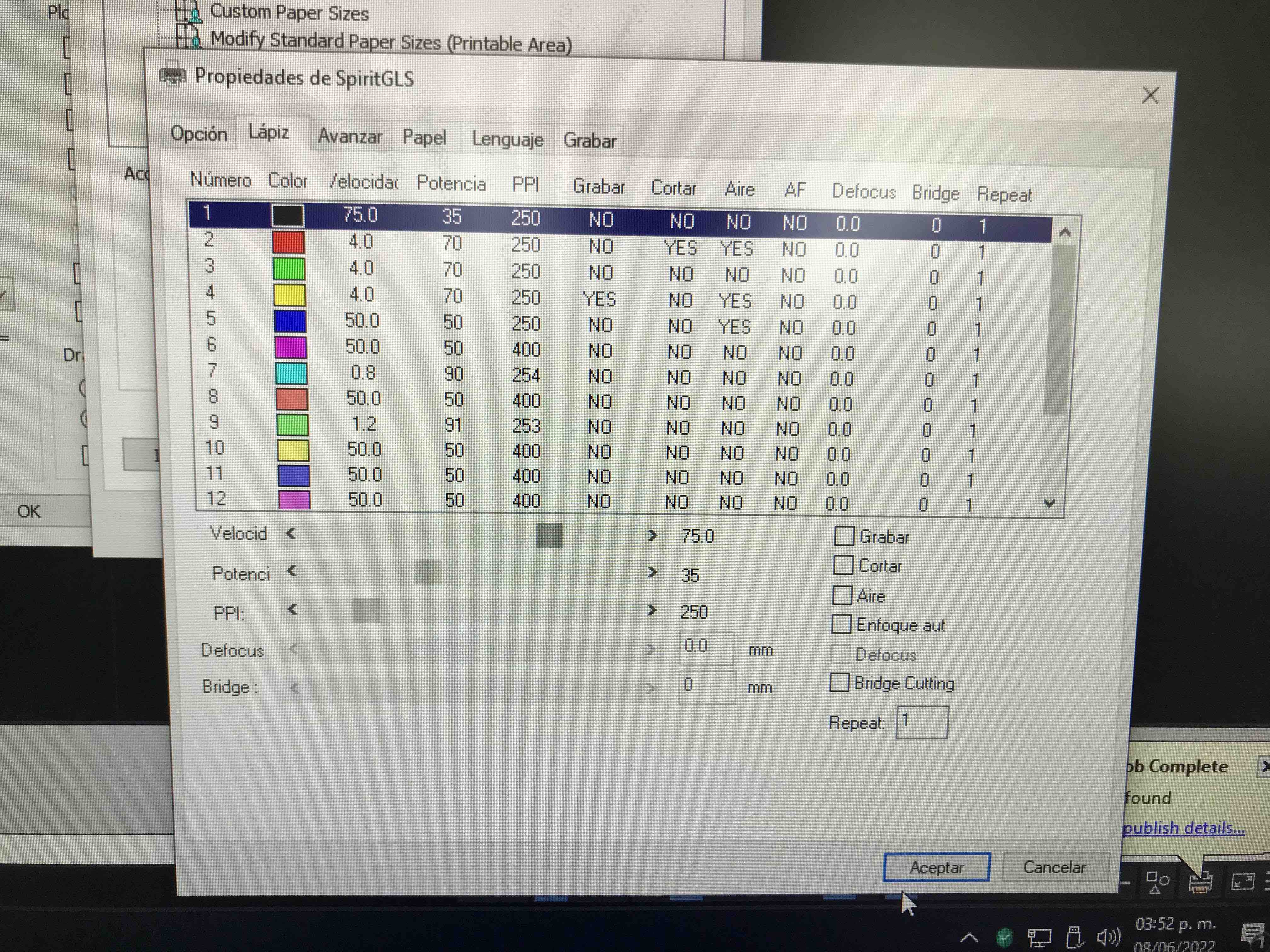
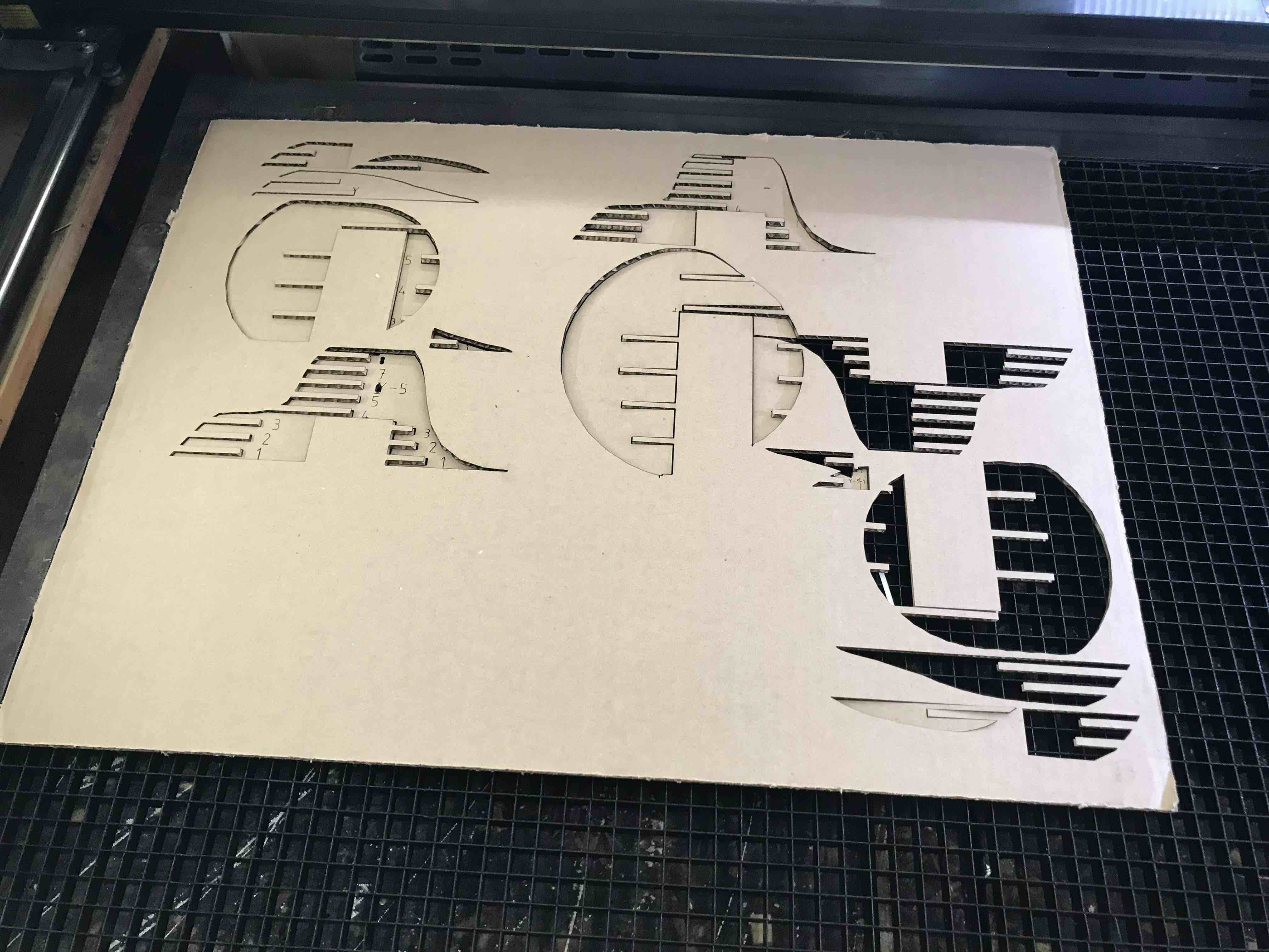
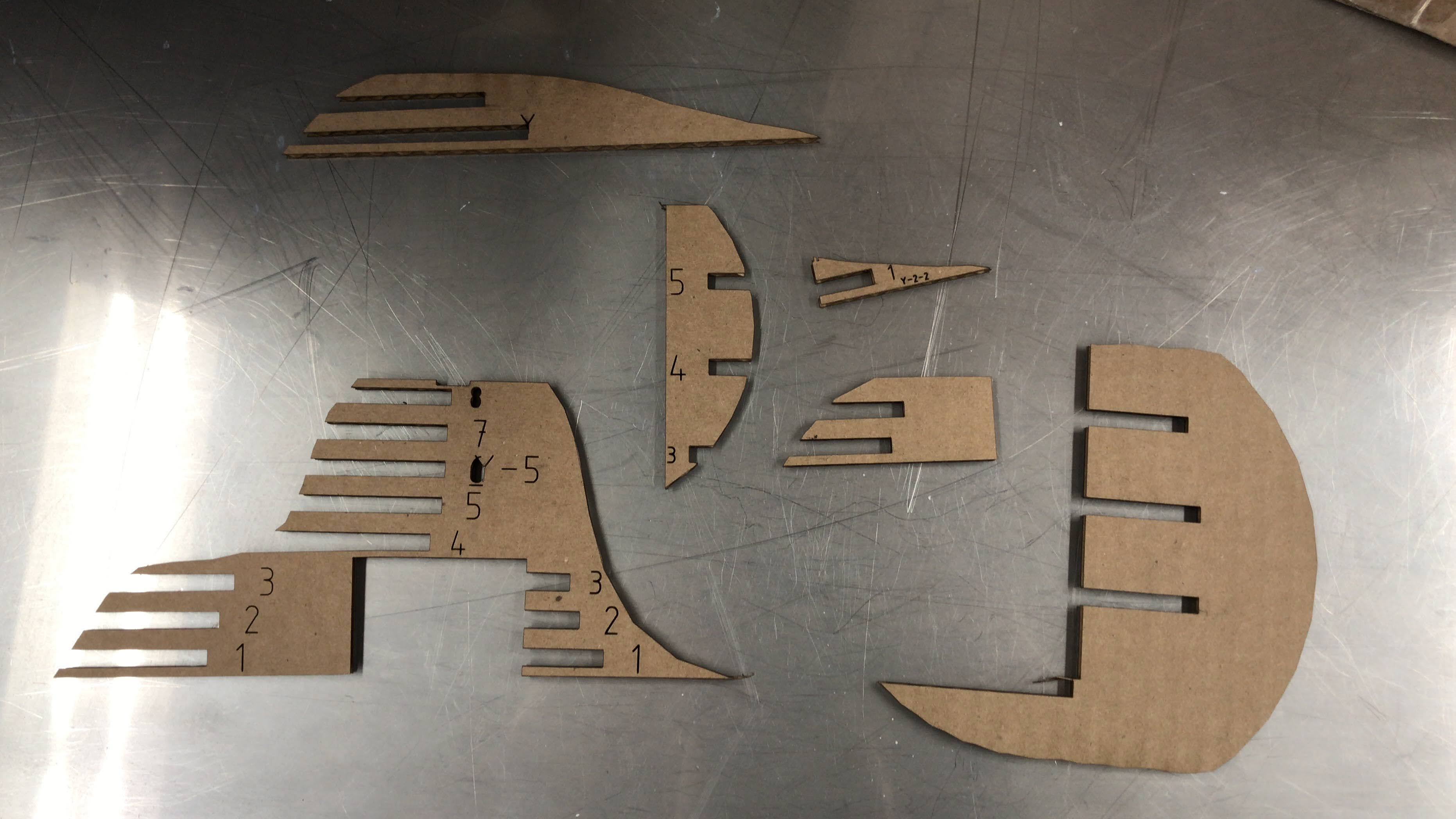
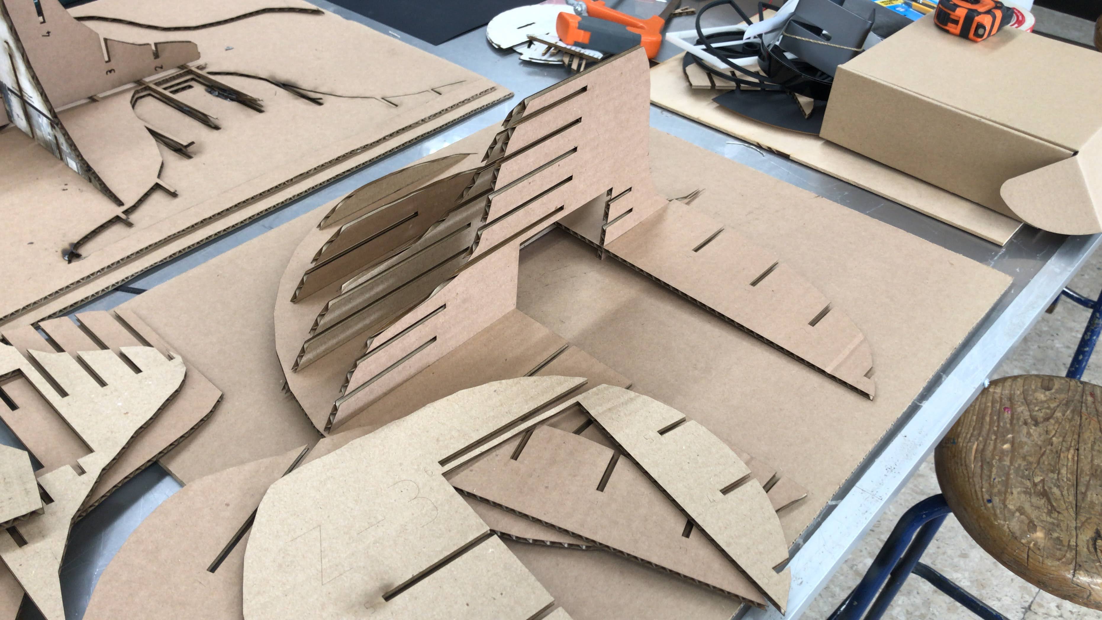
How I did it
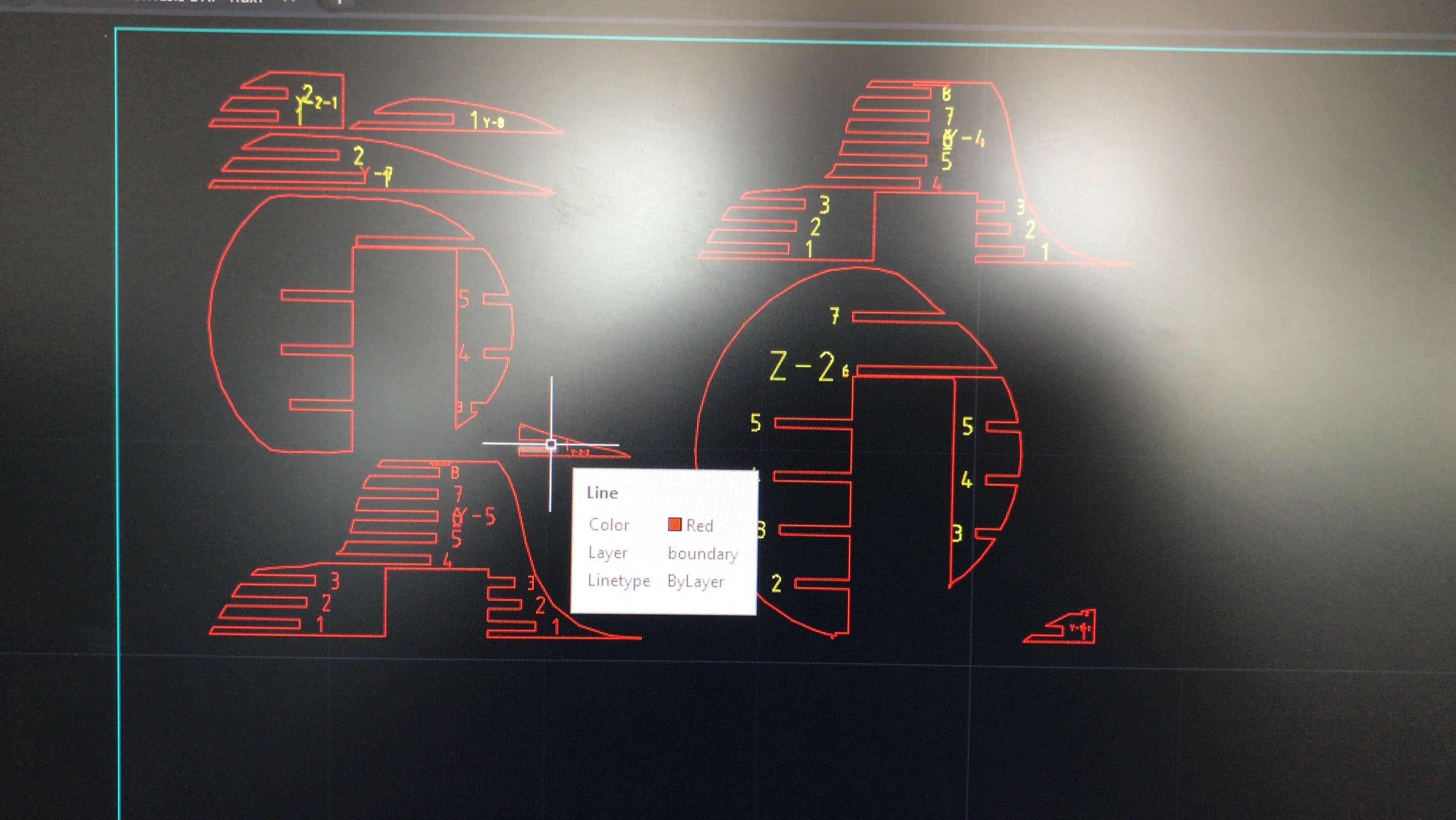
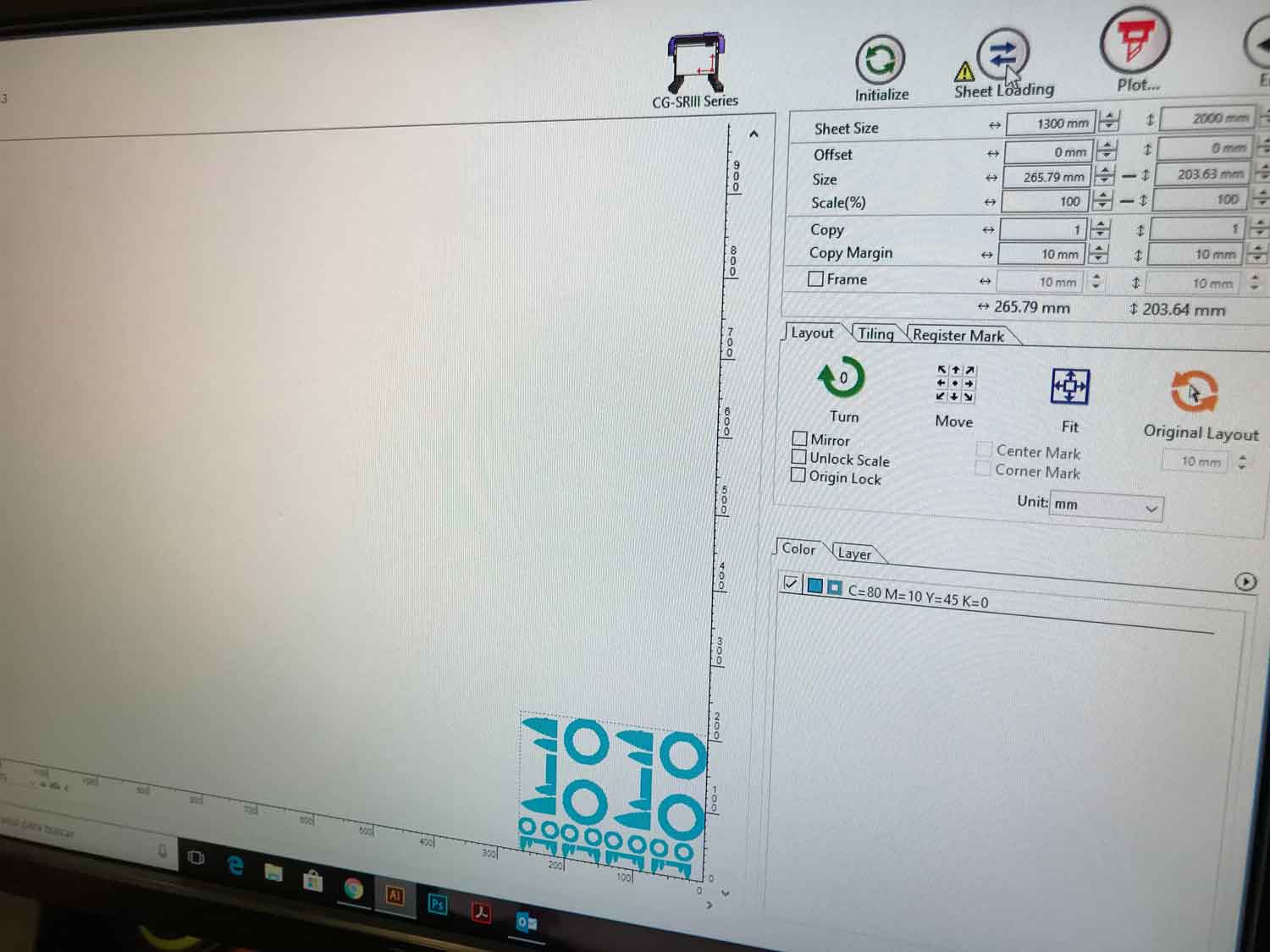
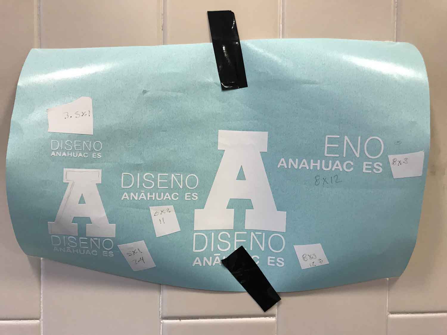
2. Then build the archive with
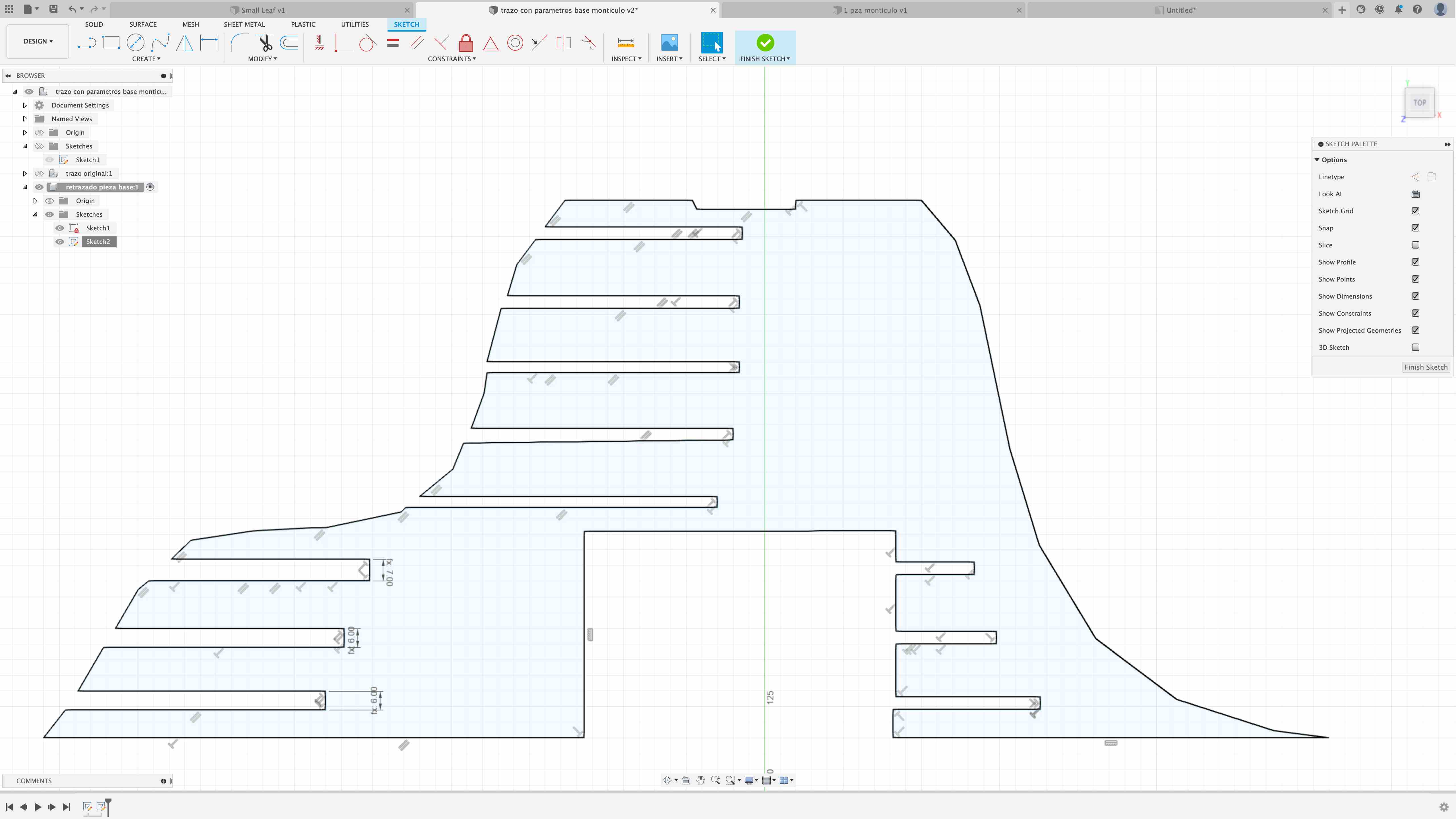
different scales of the pieces.
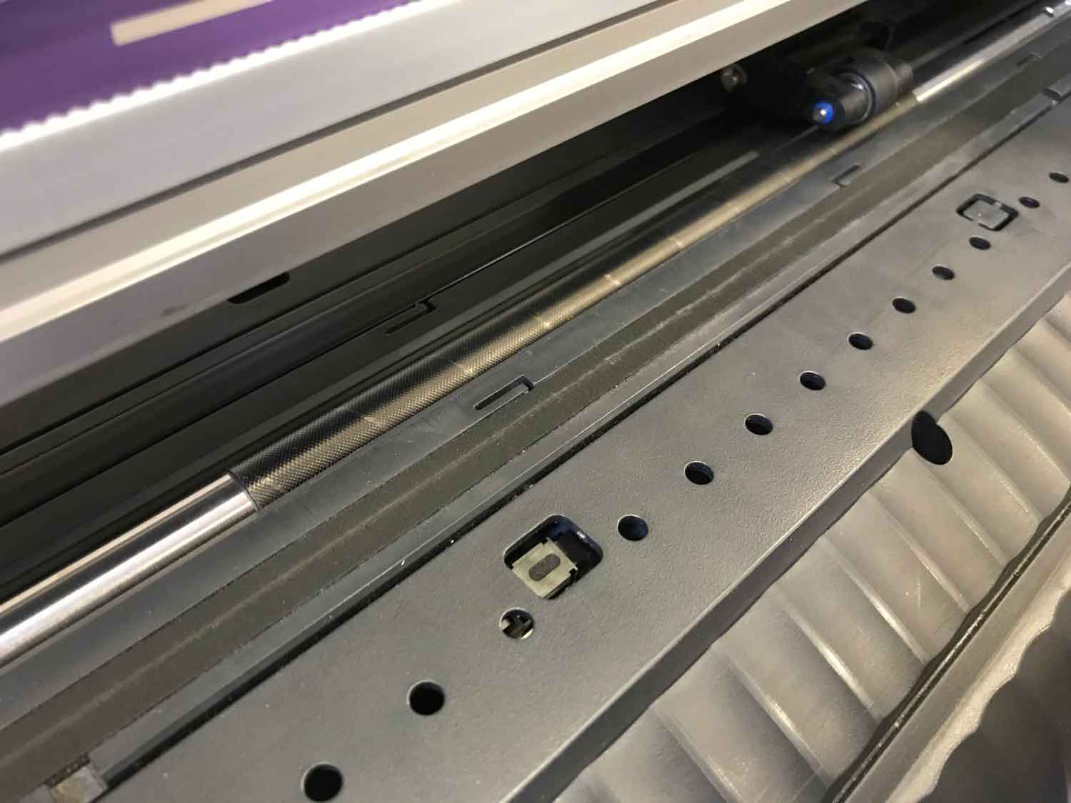
the vinylcutter machine
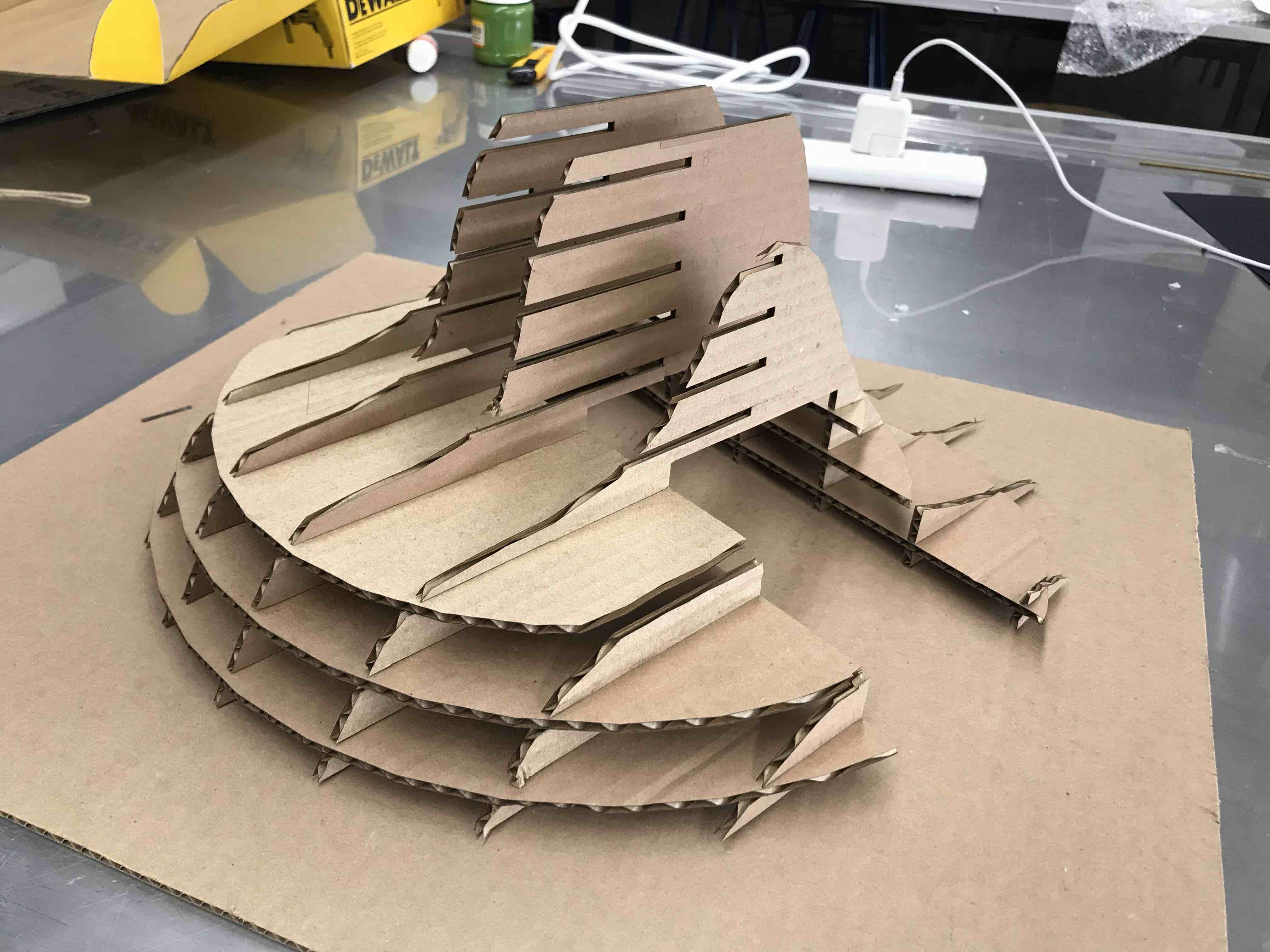
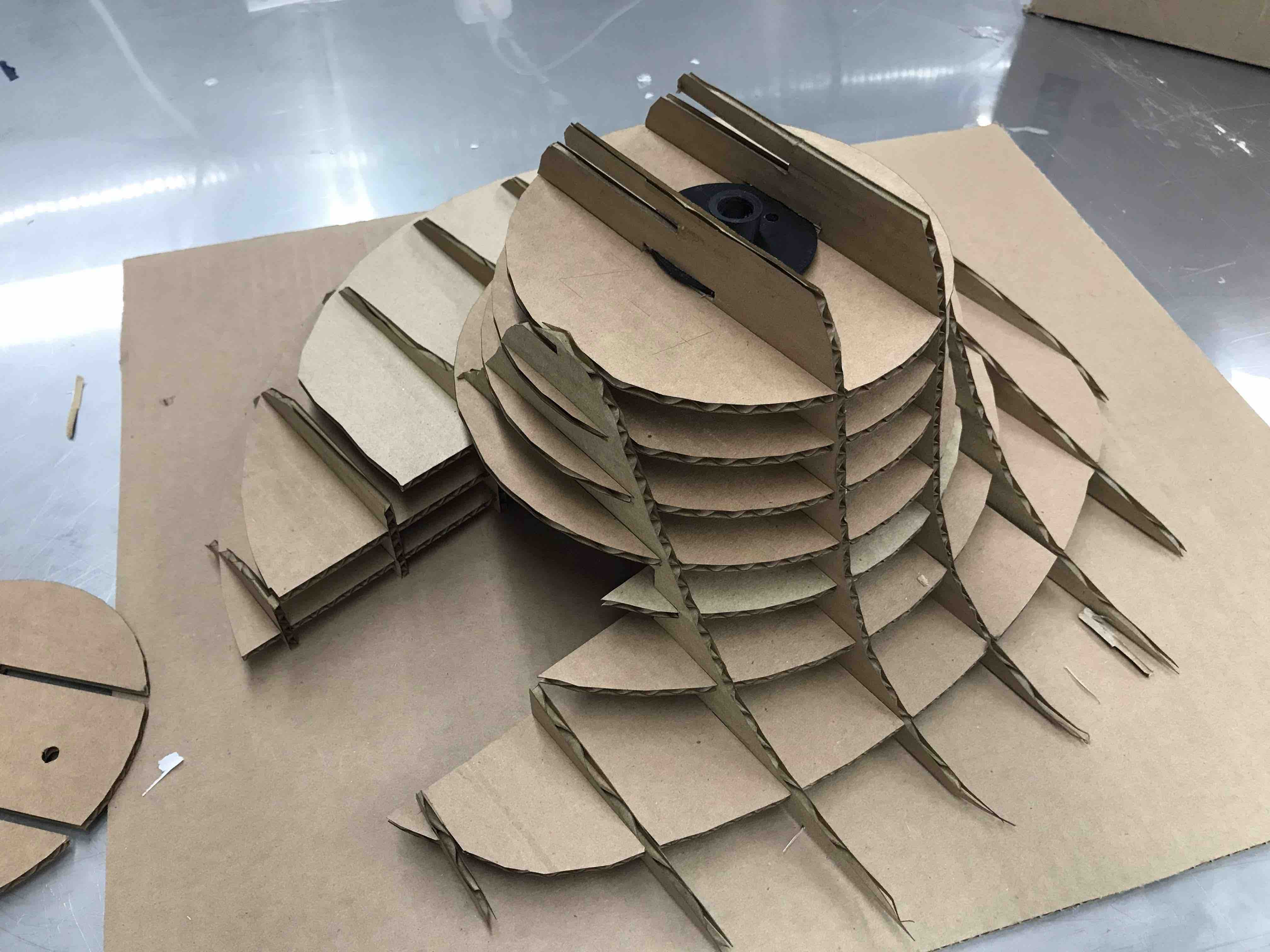
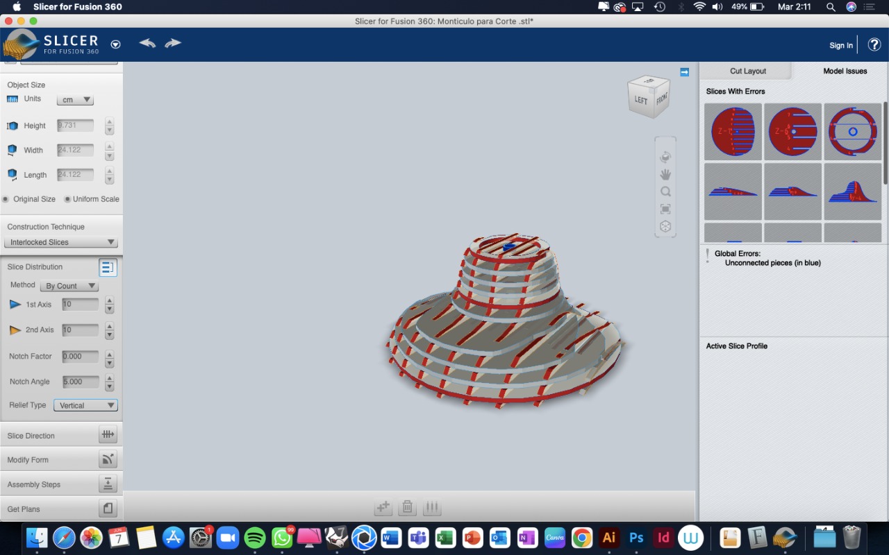
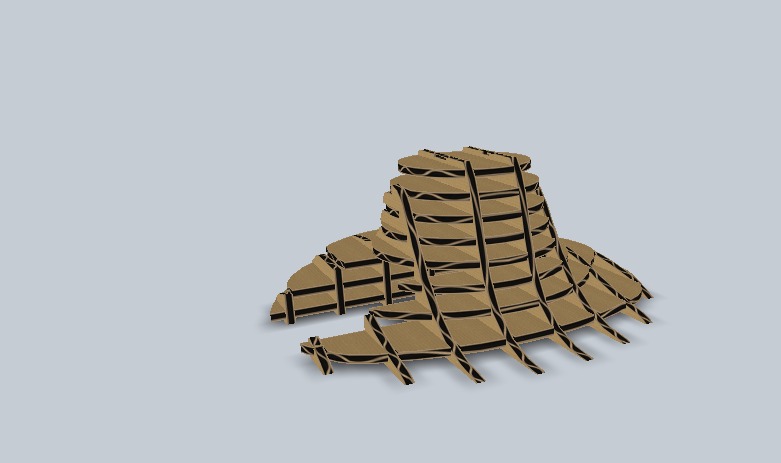
lasercutter construction kit
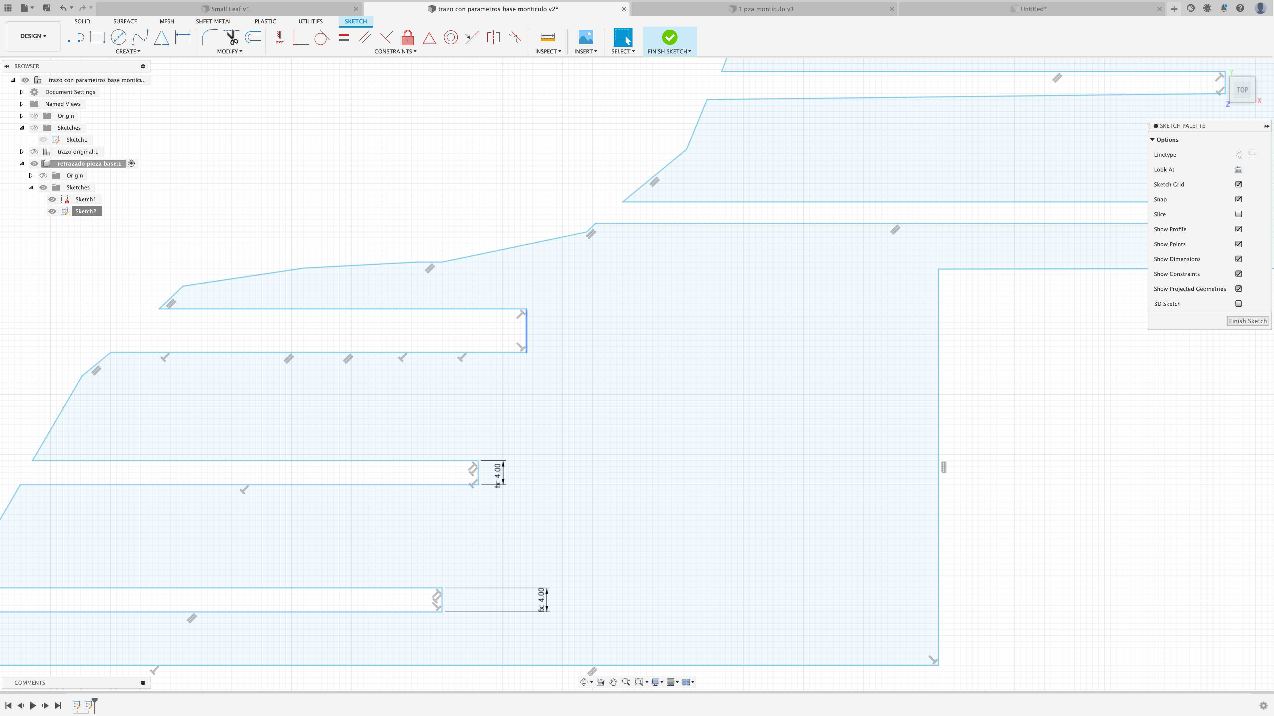
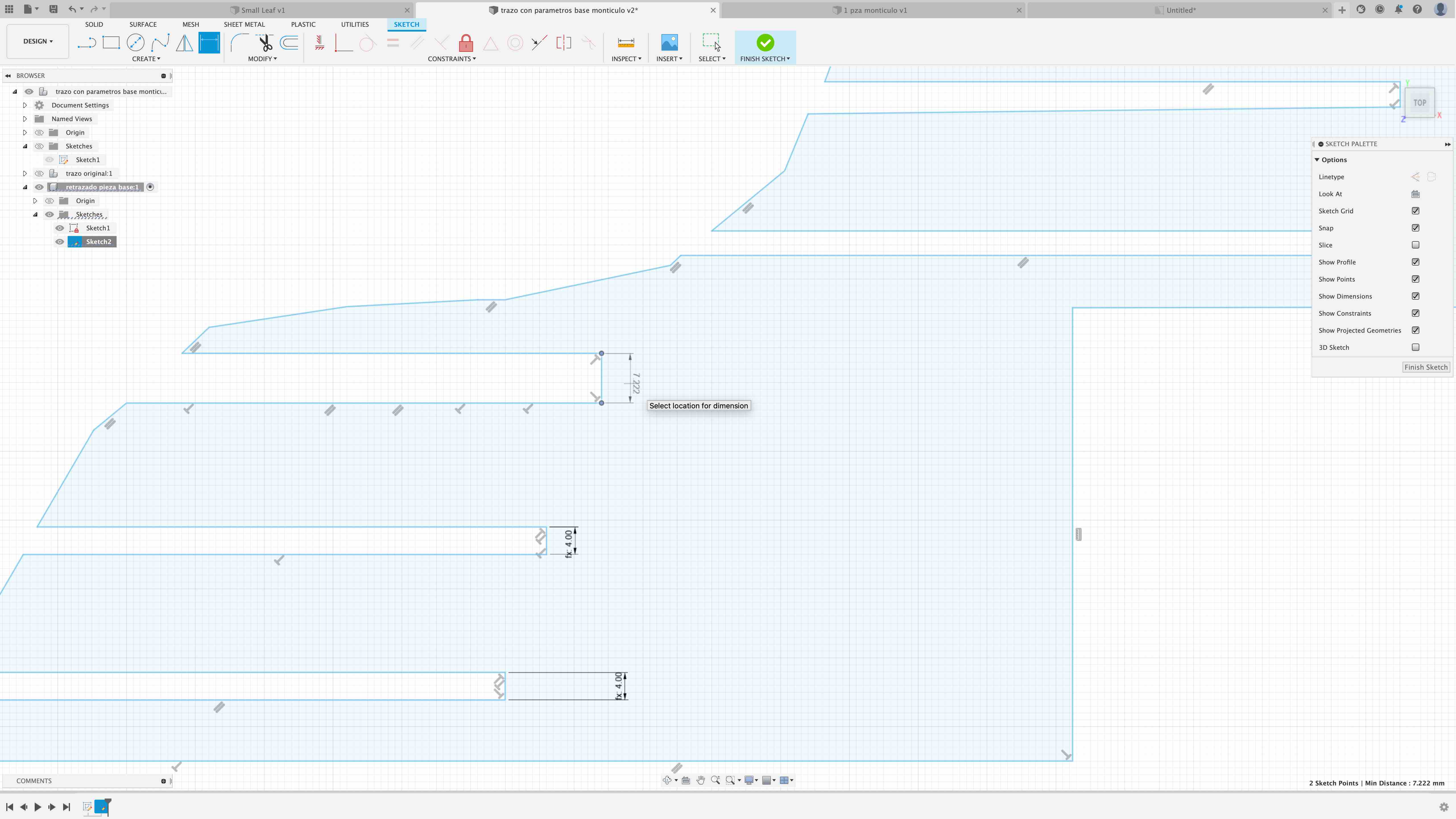
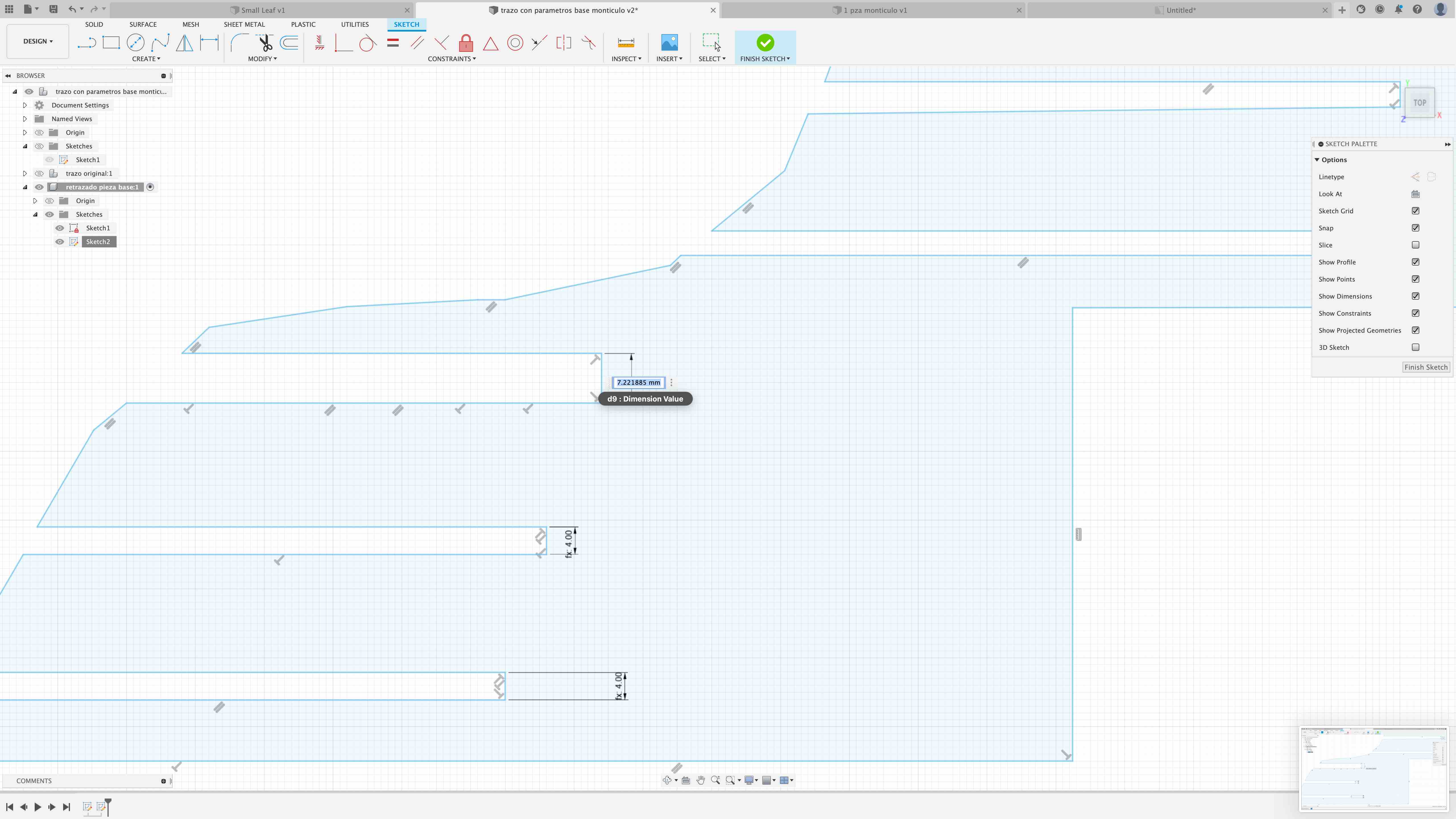
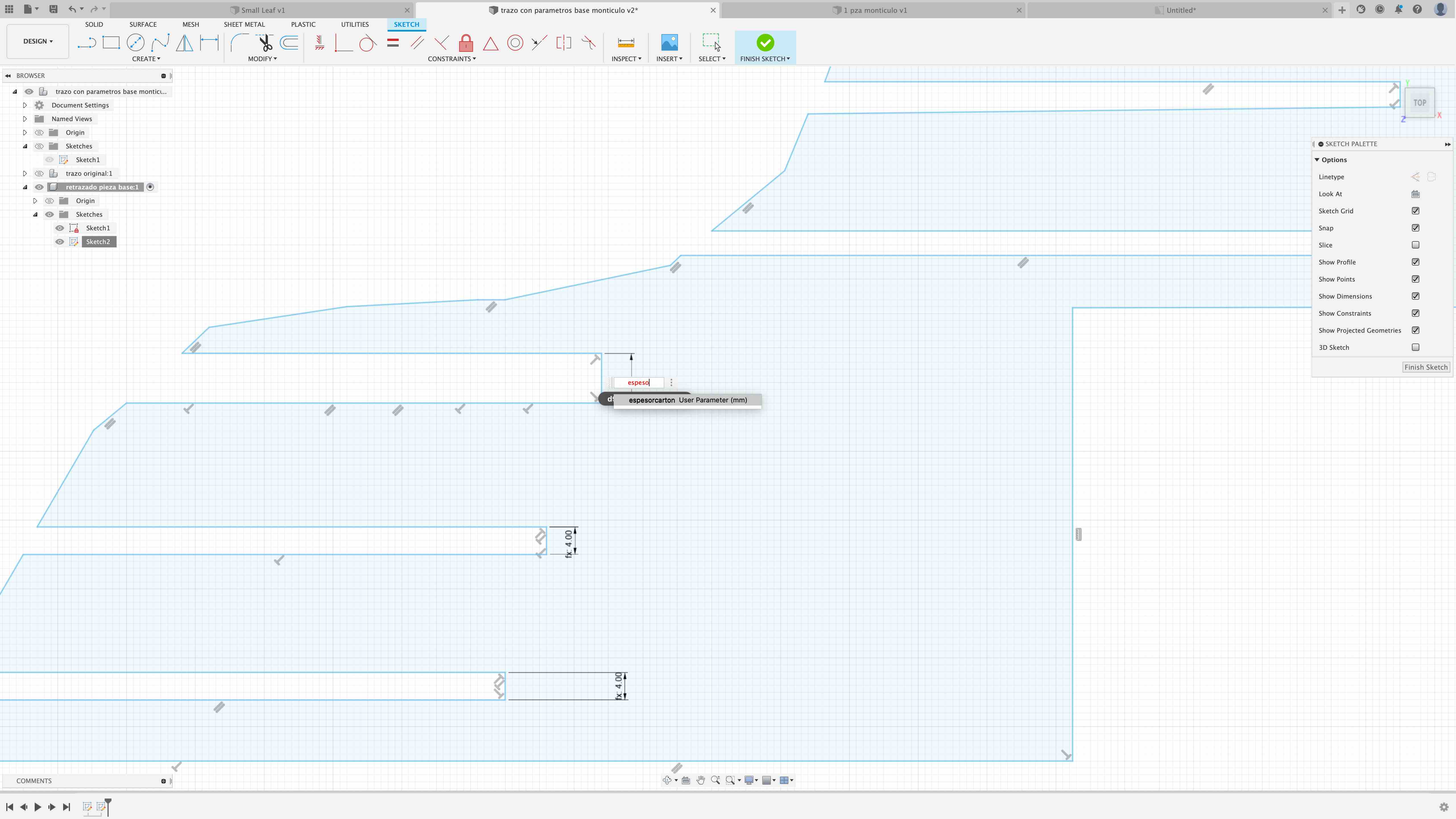
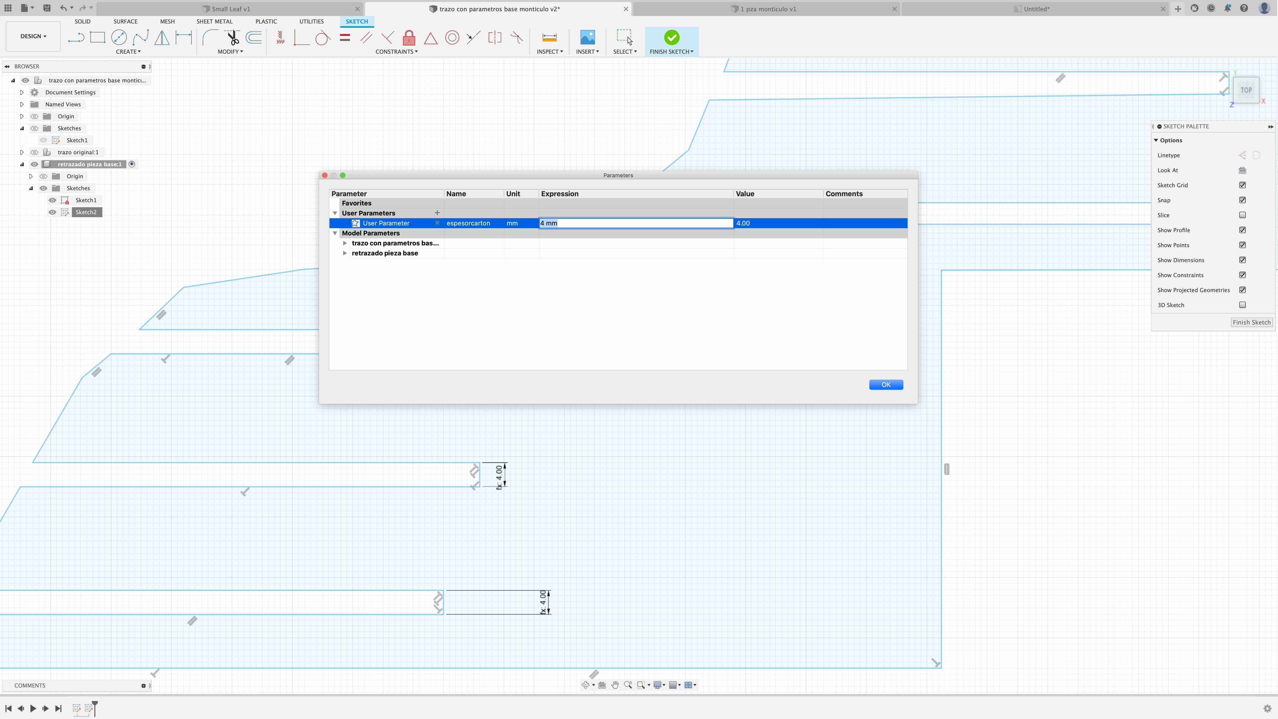
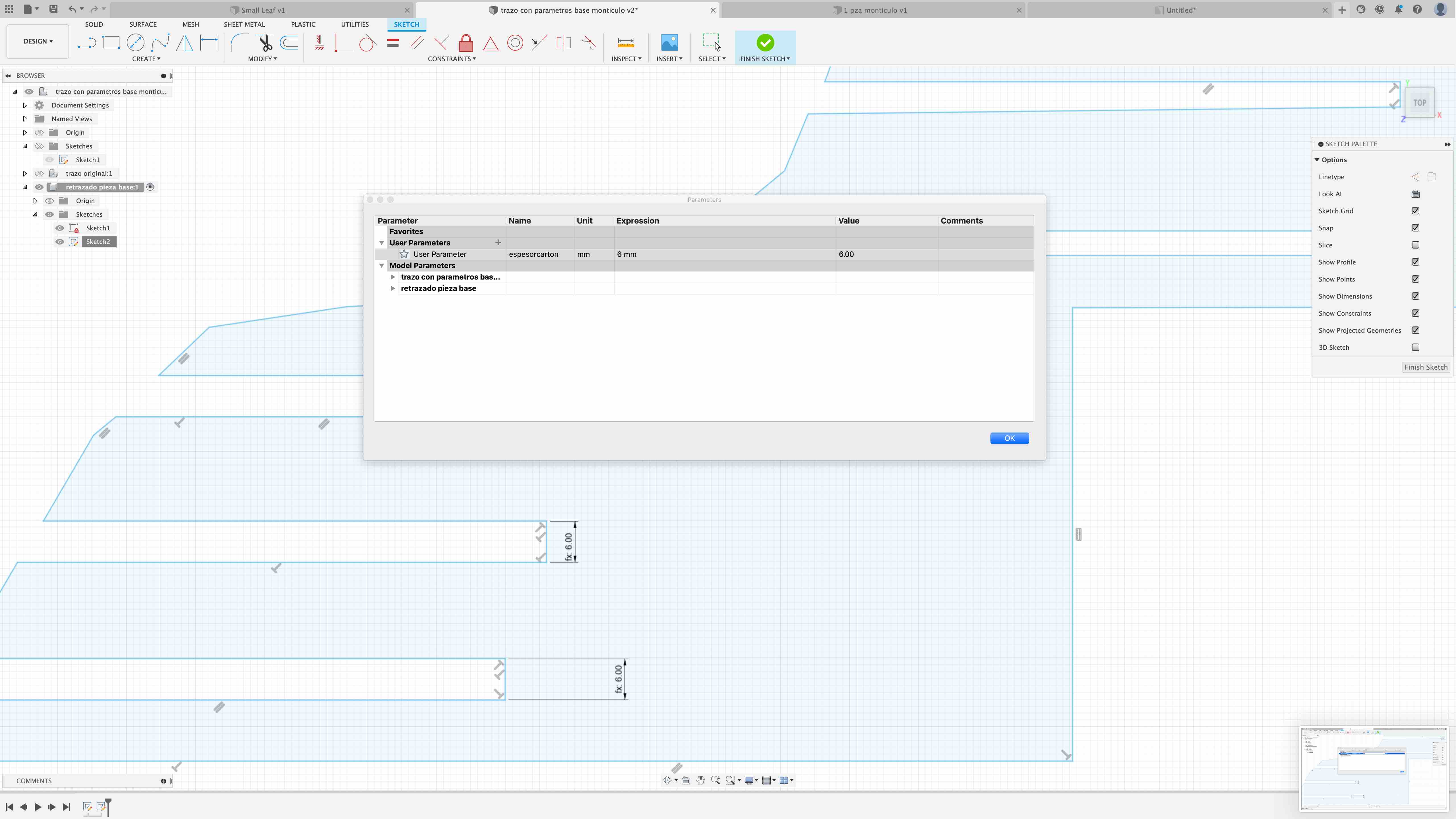
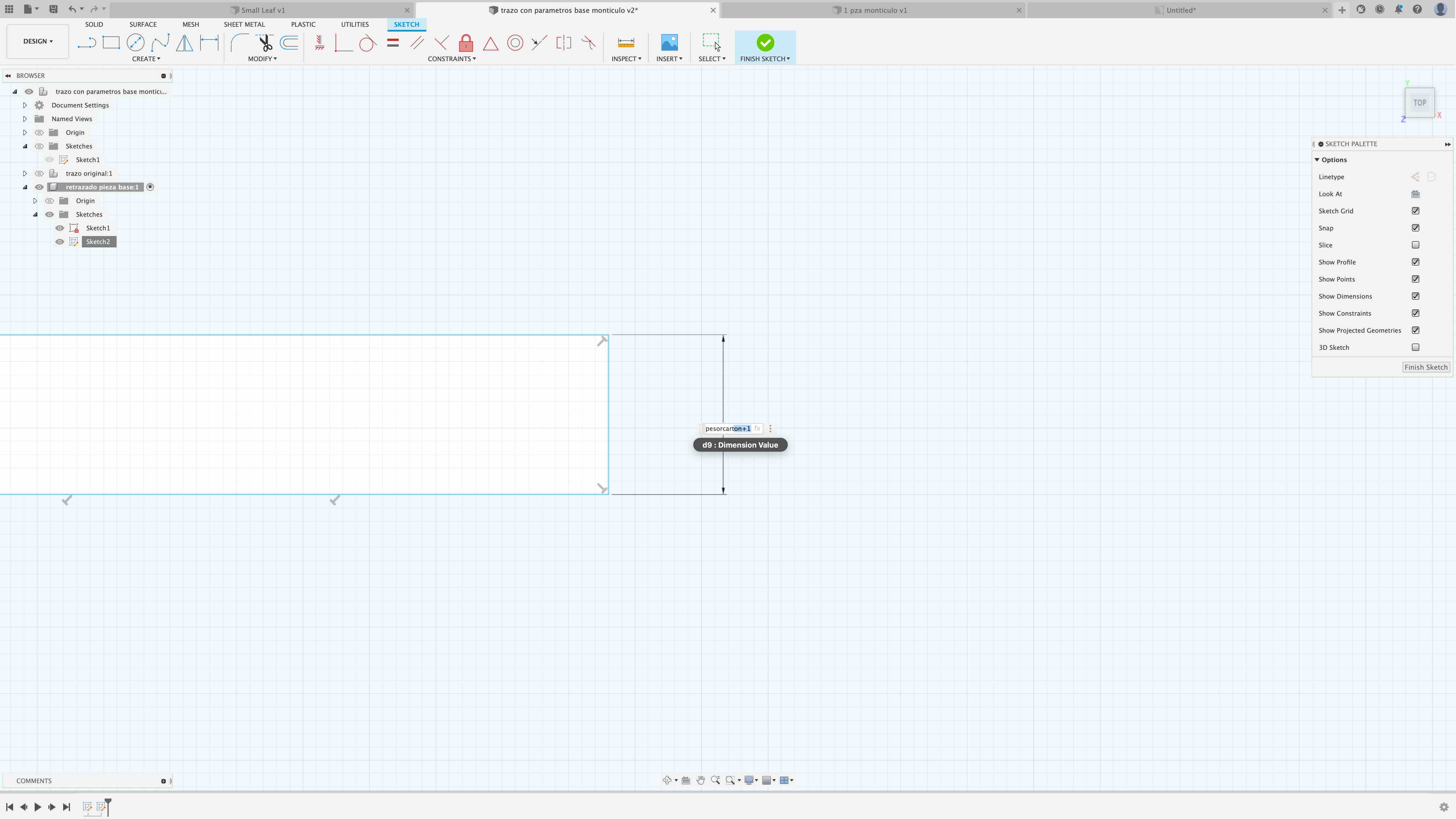
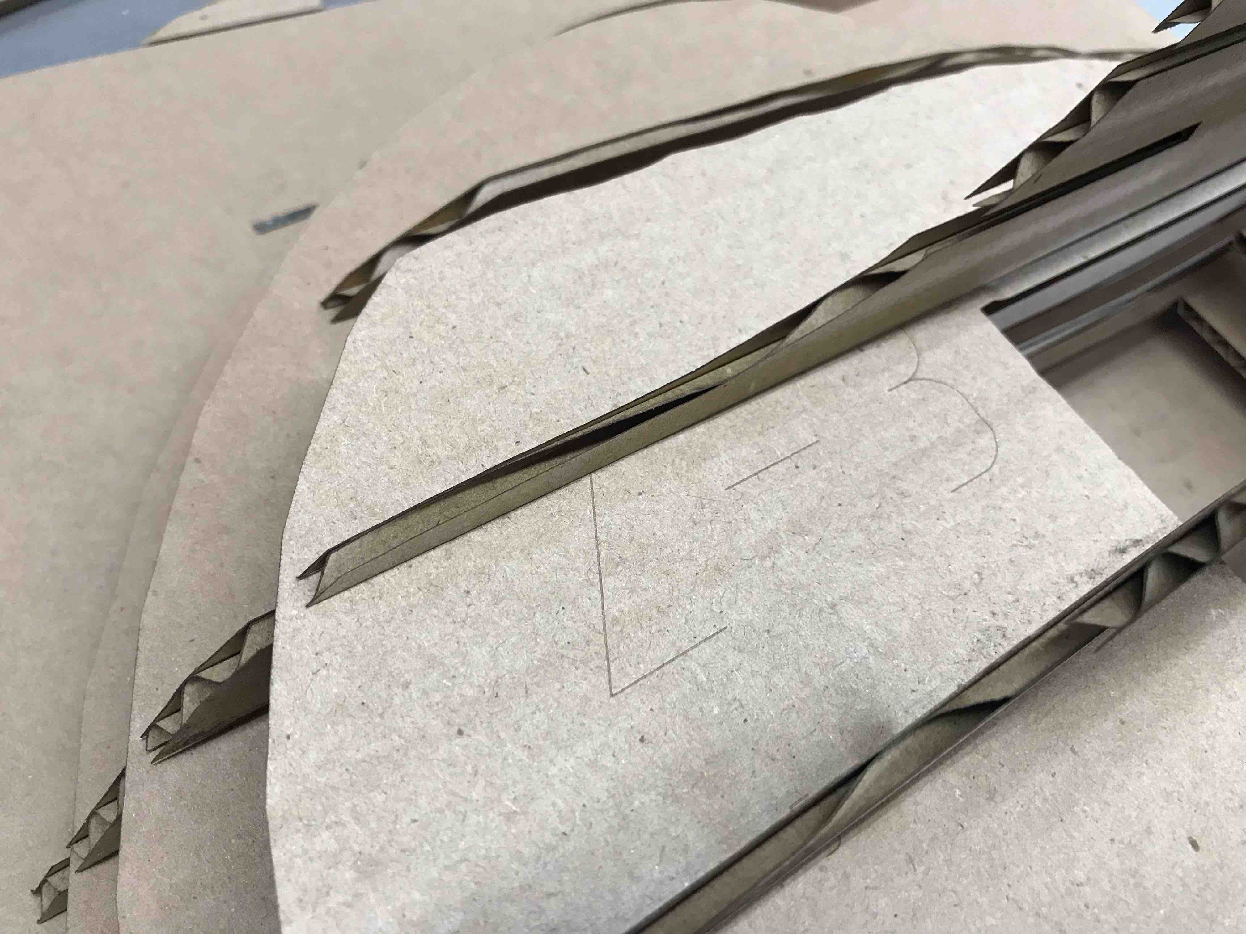
In the SKETCH mode, first select
the dimension tool of the skecth menu and then select the line
you want to measure, in my case it ws the vertical one of the
3rd slot (from below)