electronics design

First 
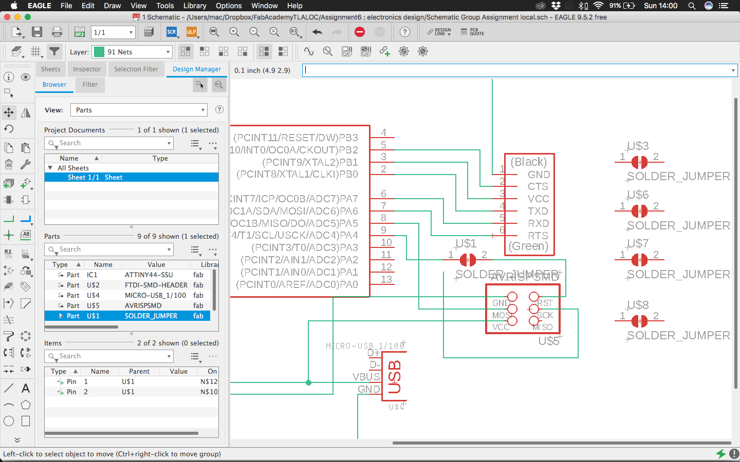
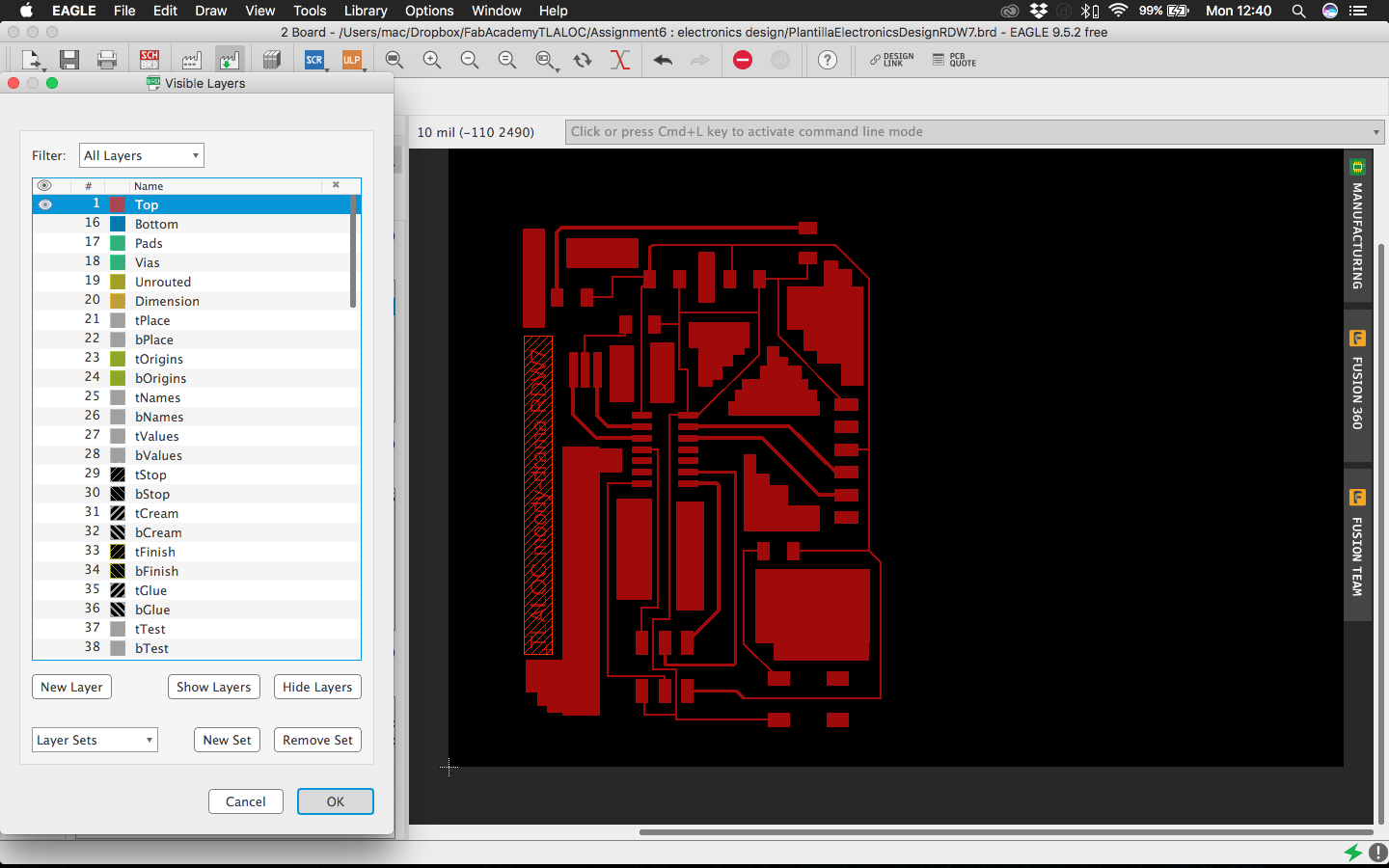
we practice as a Group Assignment and as a homework to redraw an existing PCB to explore and become familiar with EAGLE, from Schematic to the board, using different width of traces, putting some jumpers to avoid crossroads, etc
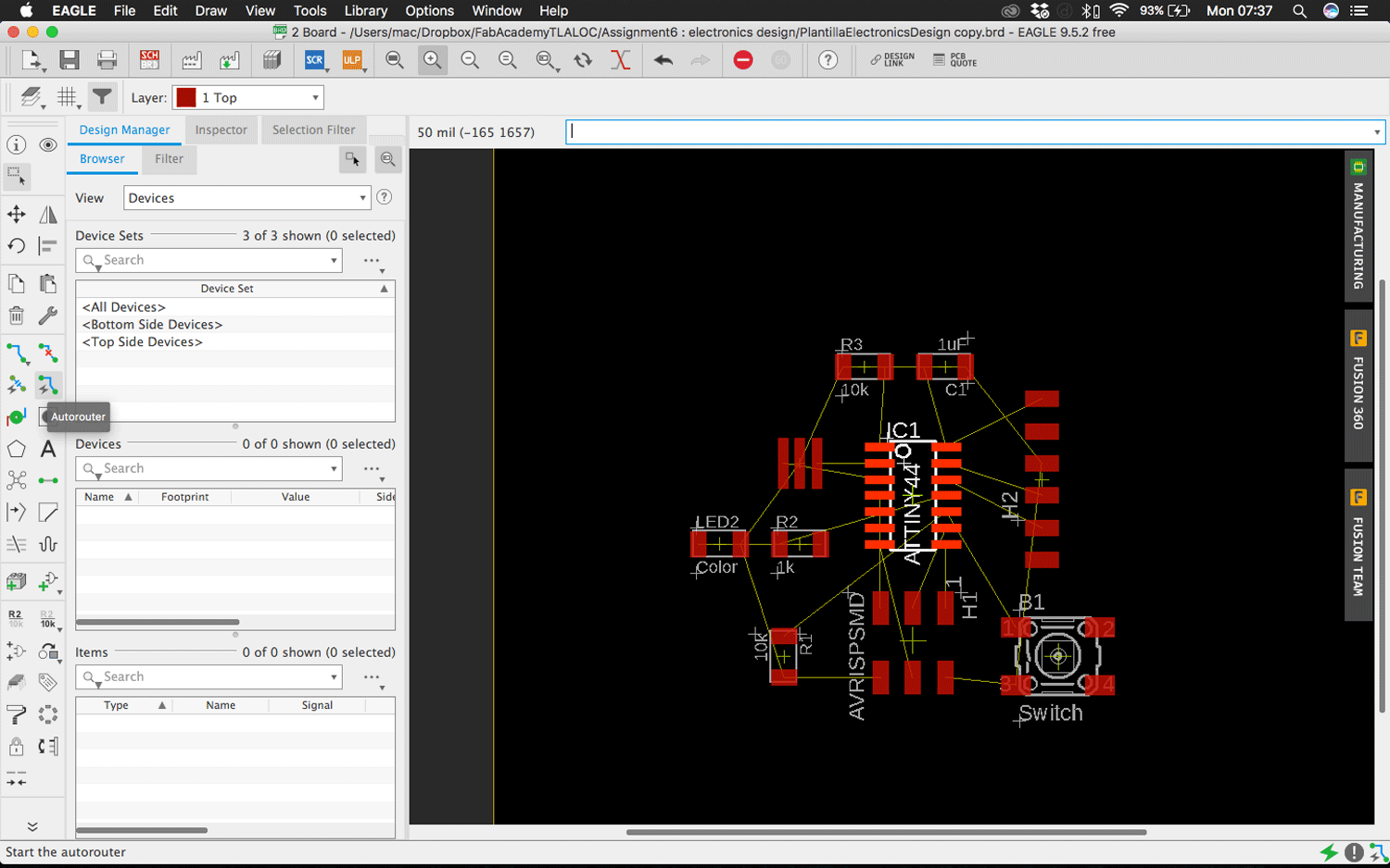
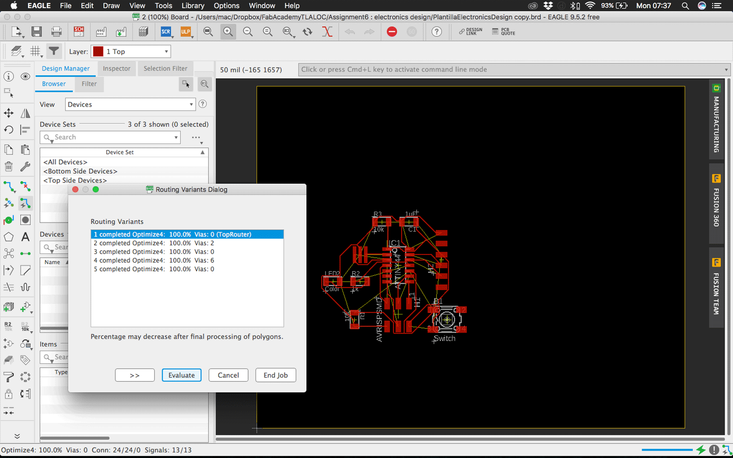
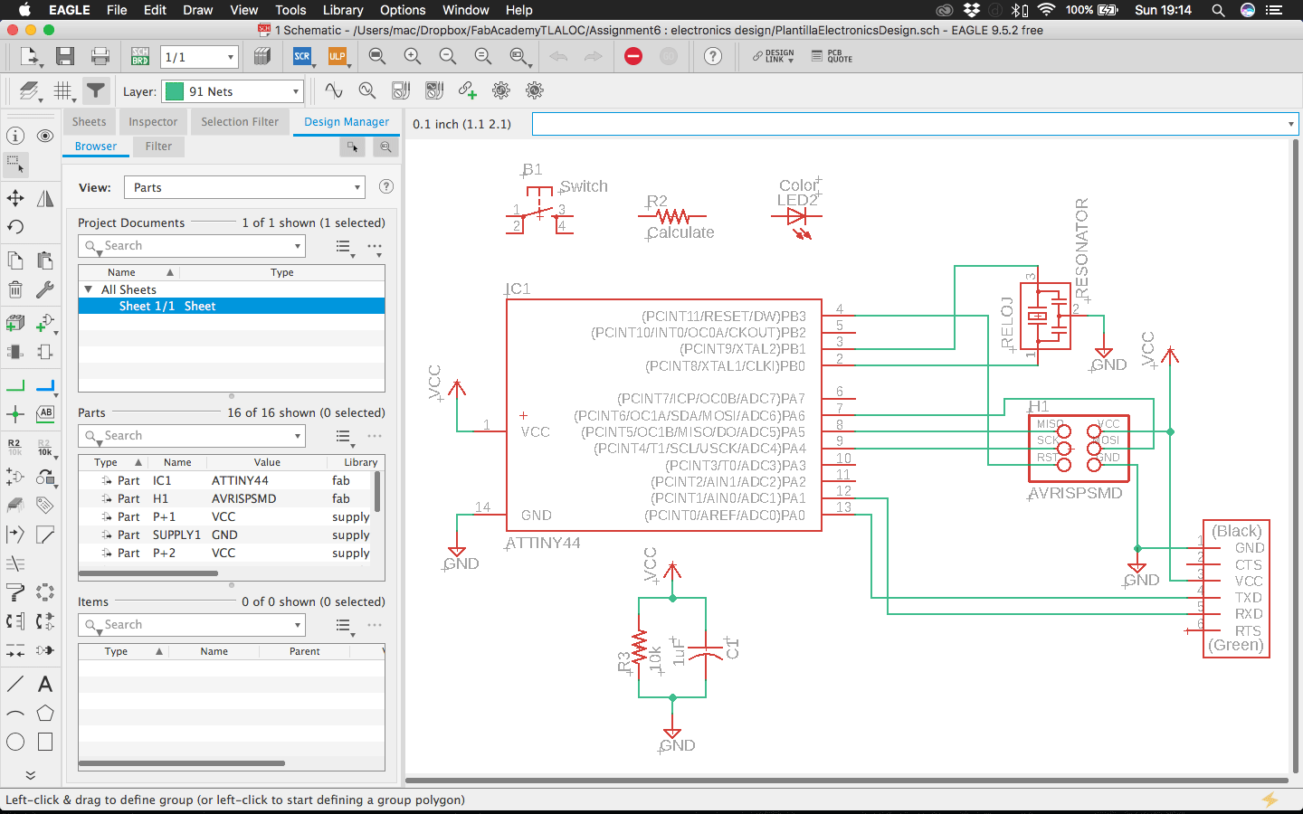
Then 
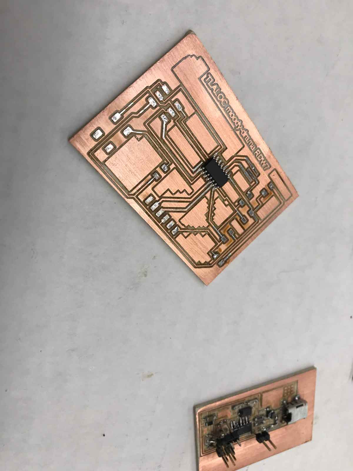
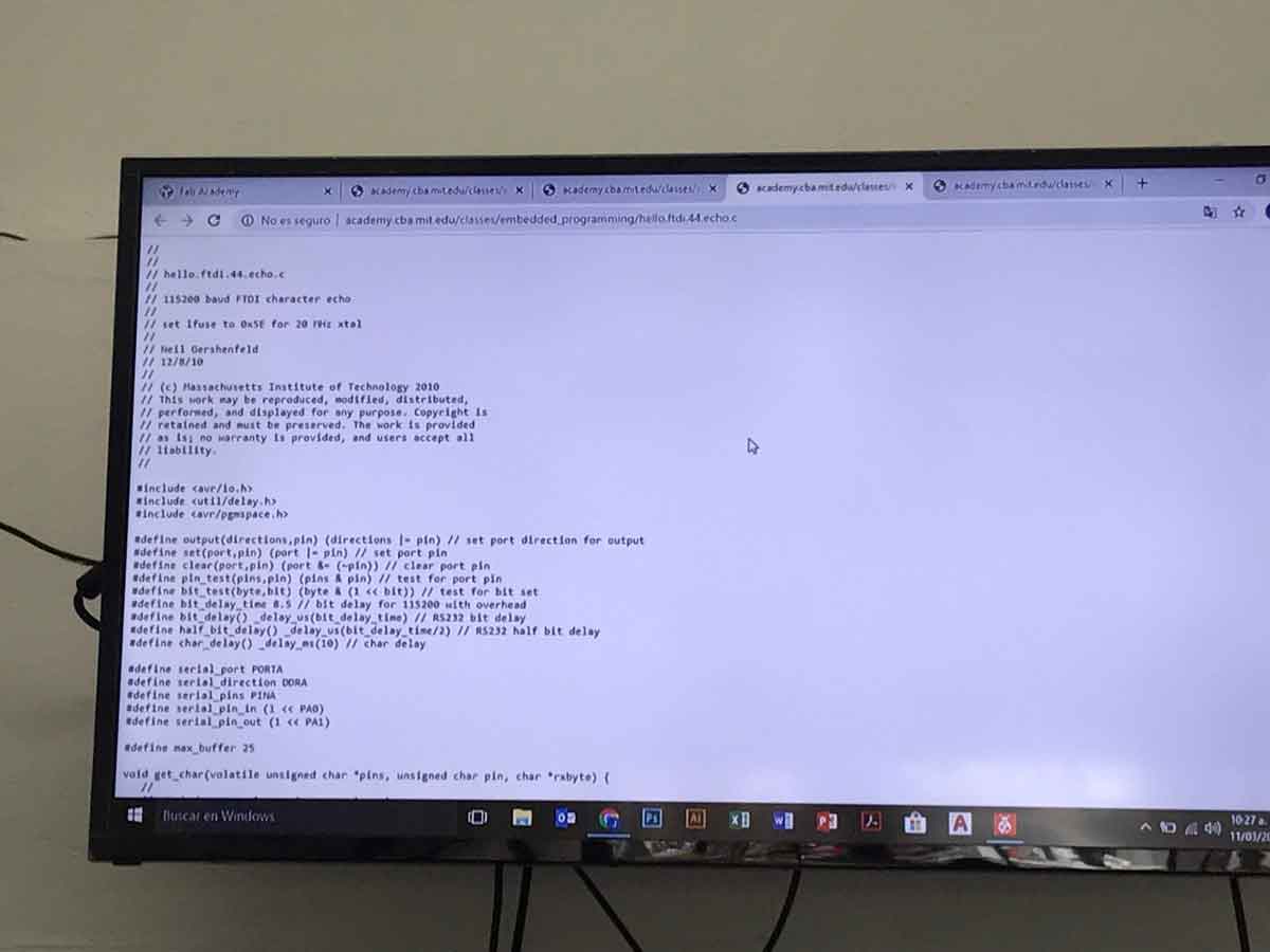
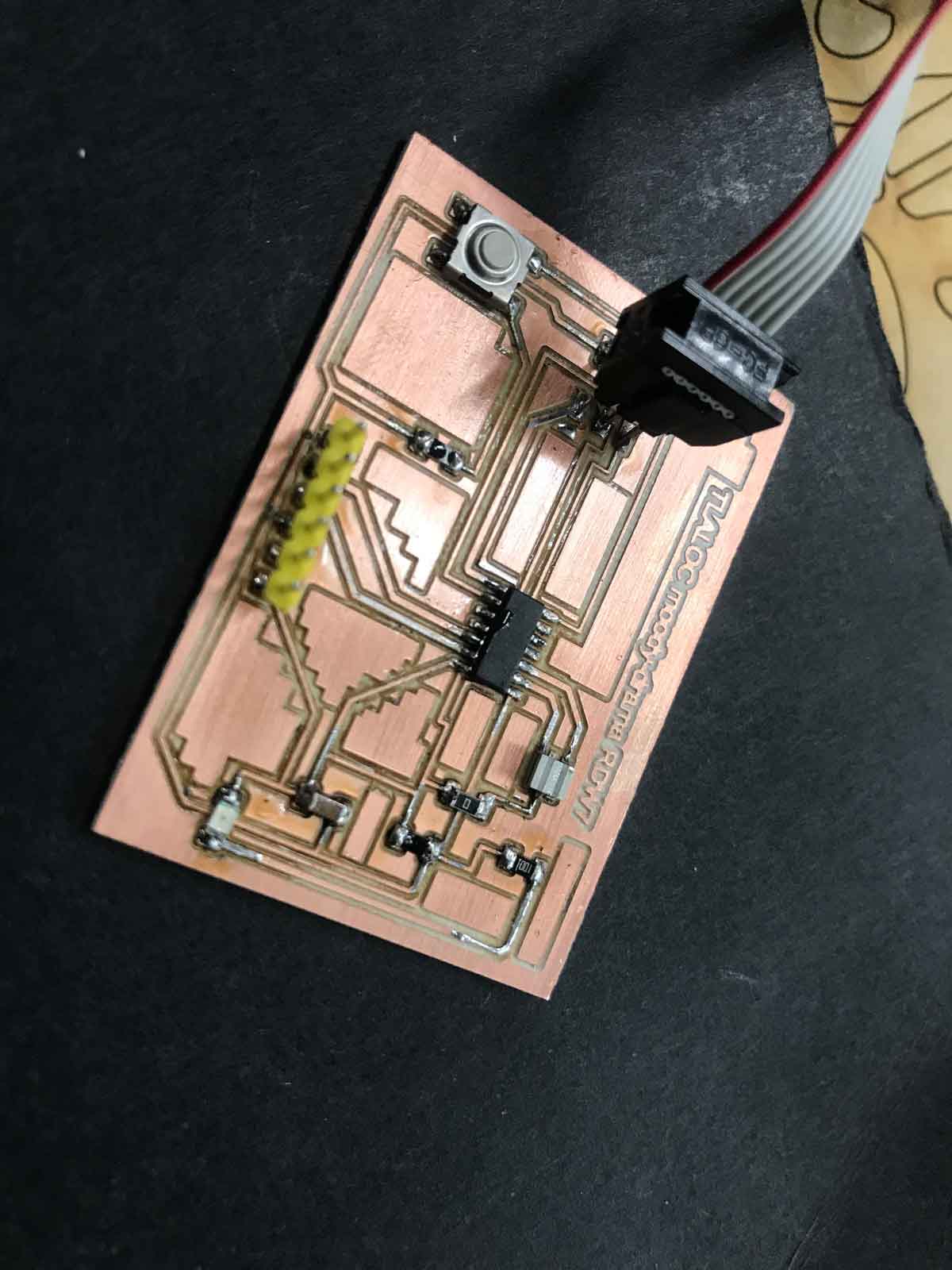
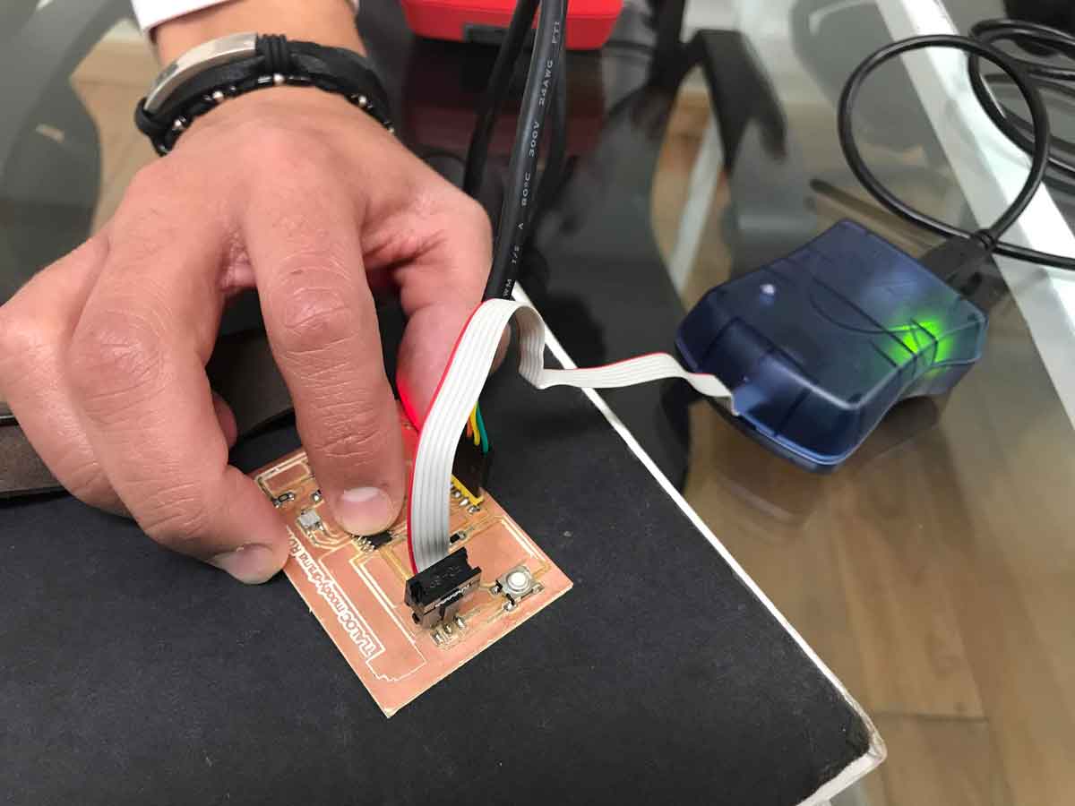
we start the individual assignment : redraw a echo hello- world board , add at least a BUTTON and LED and the current limiting resistor.

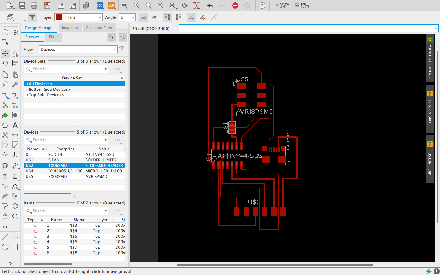
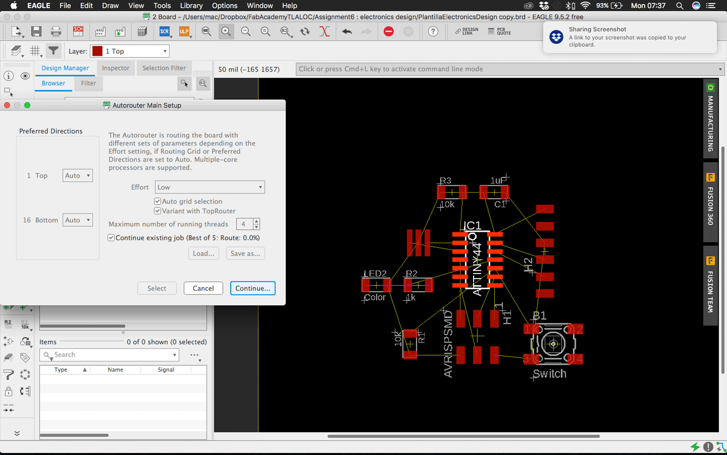
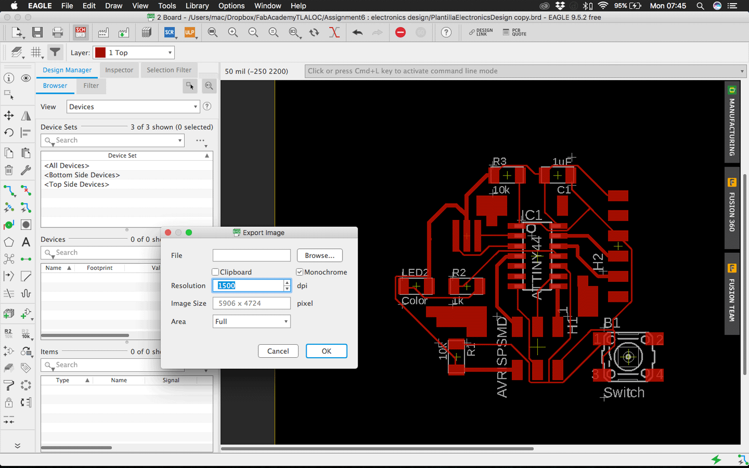
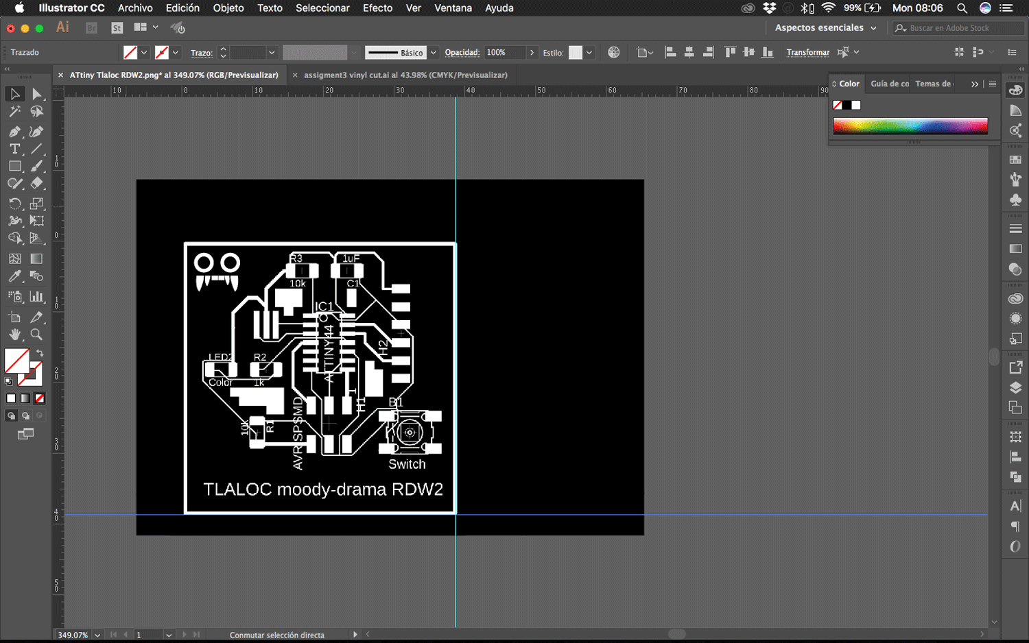
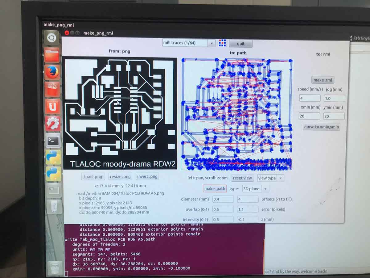
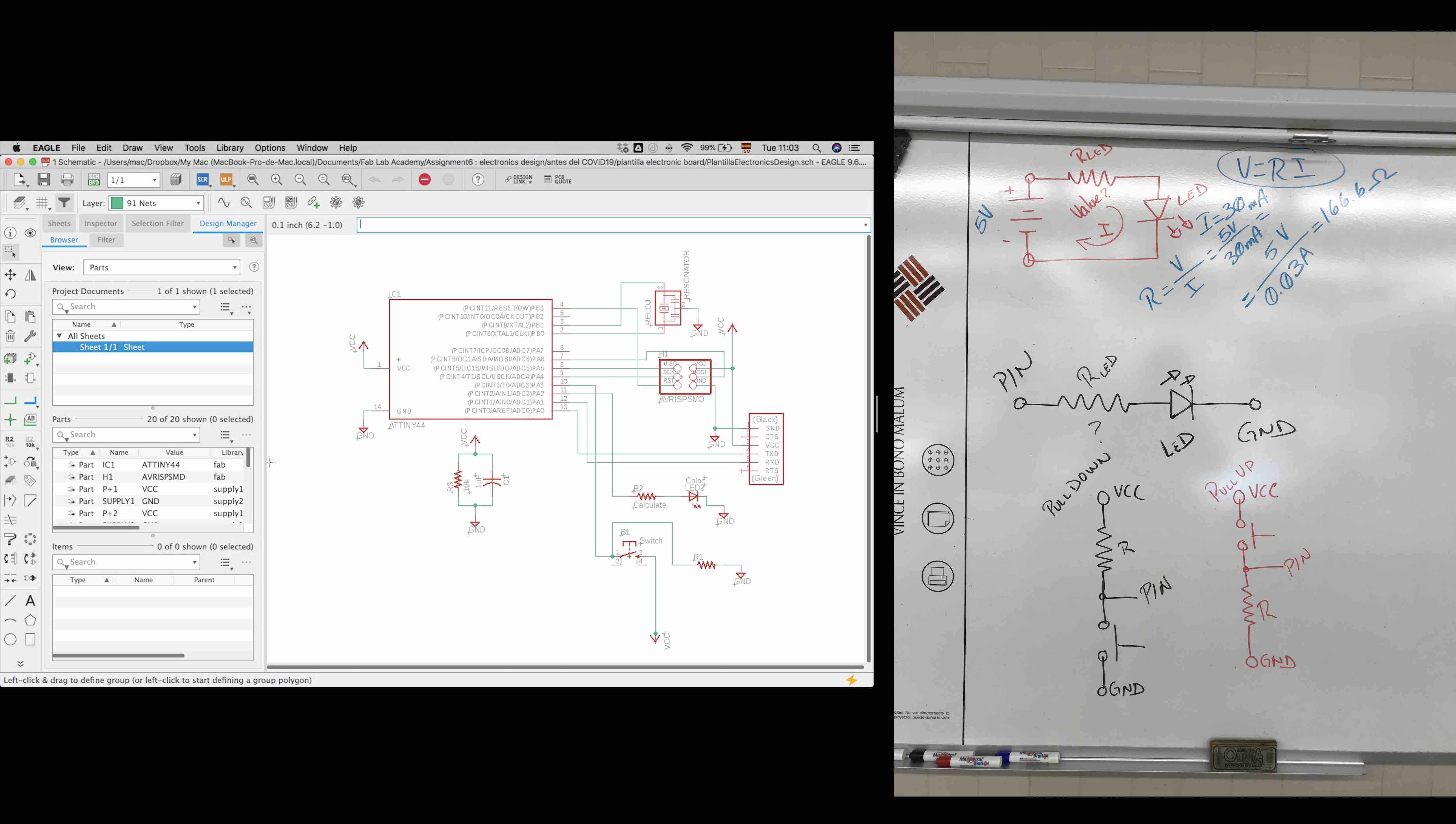
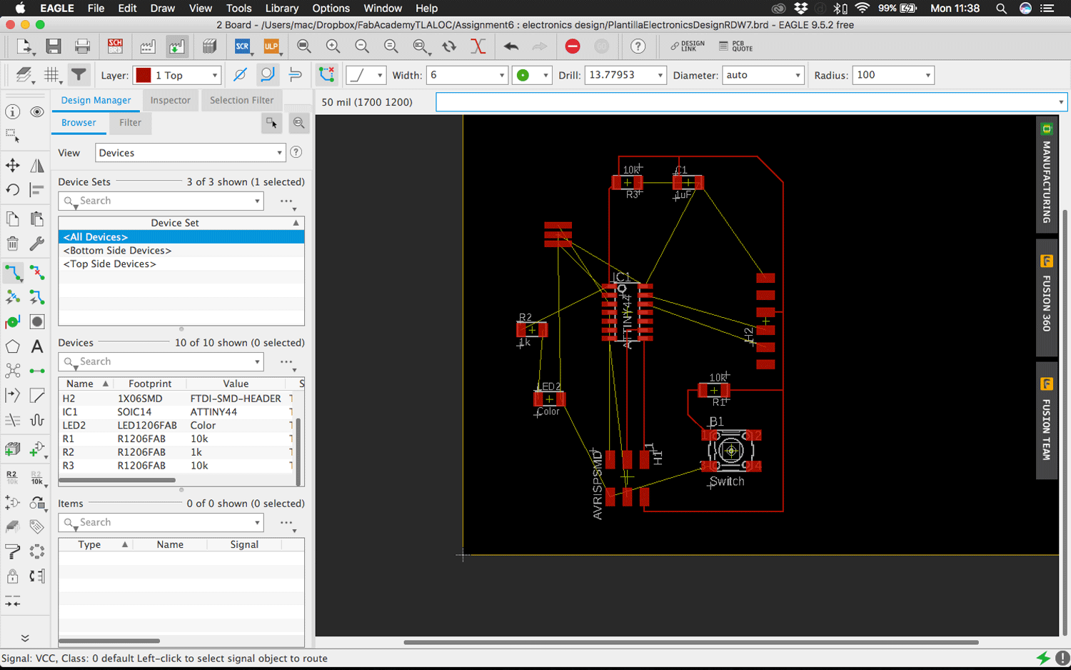
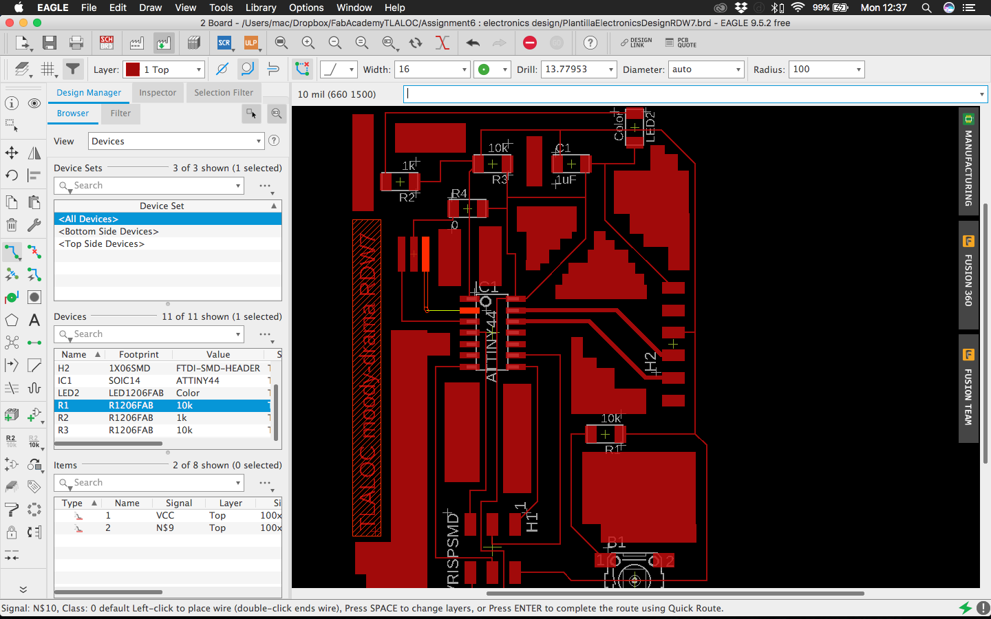
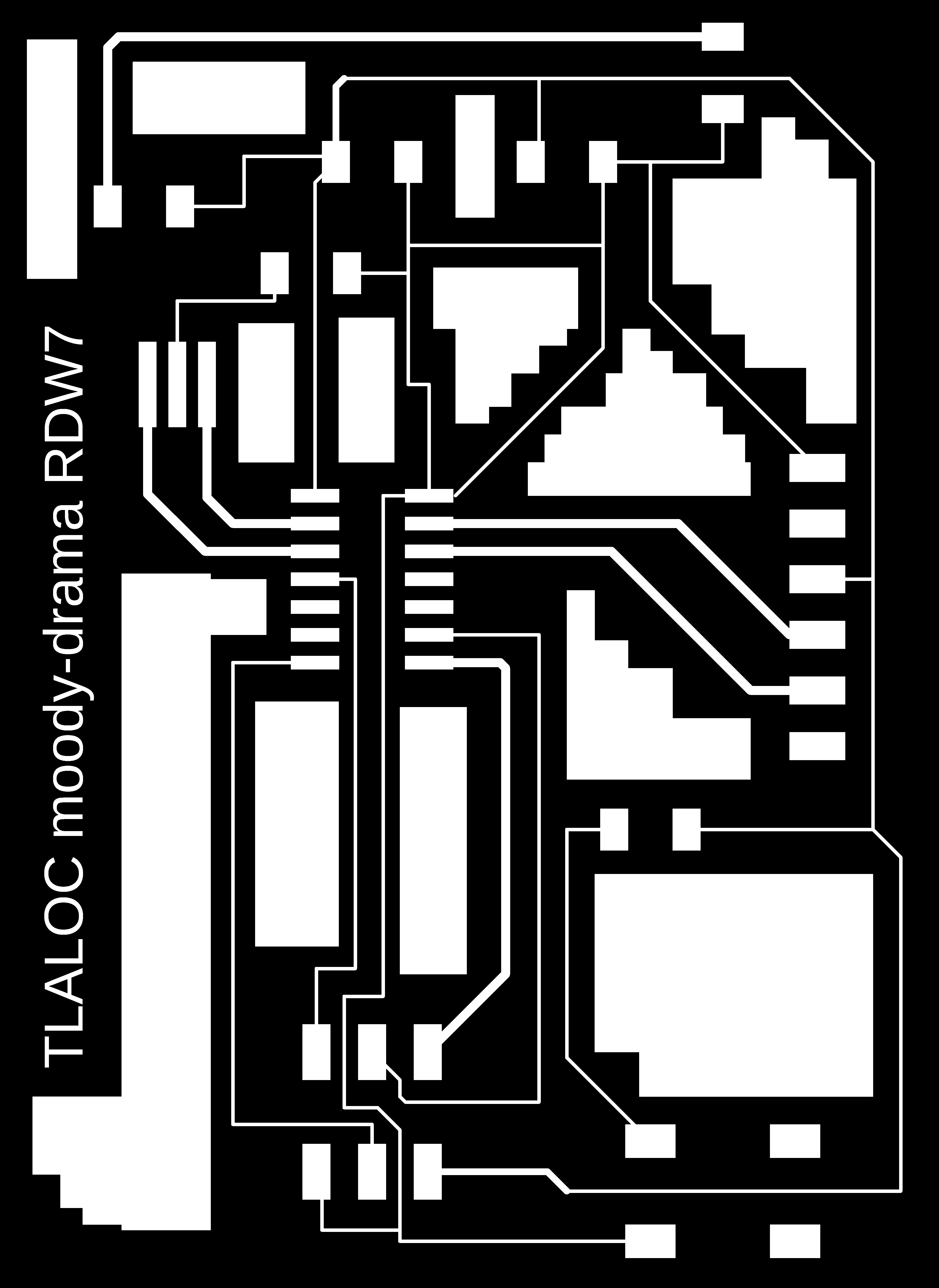
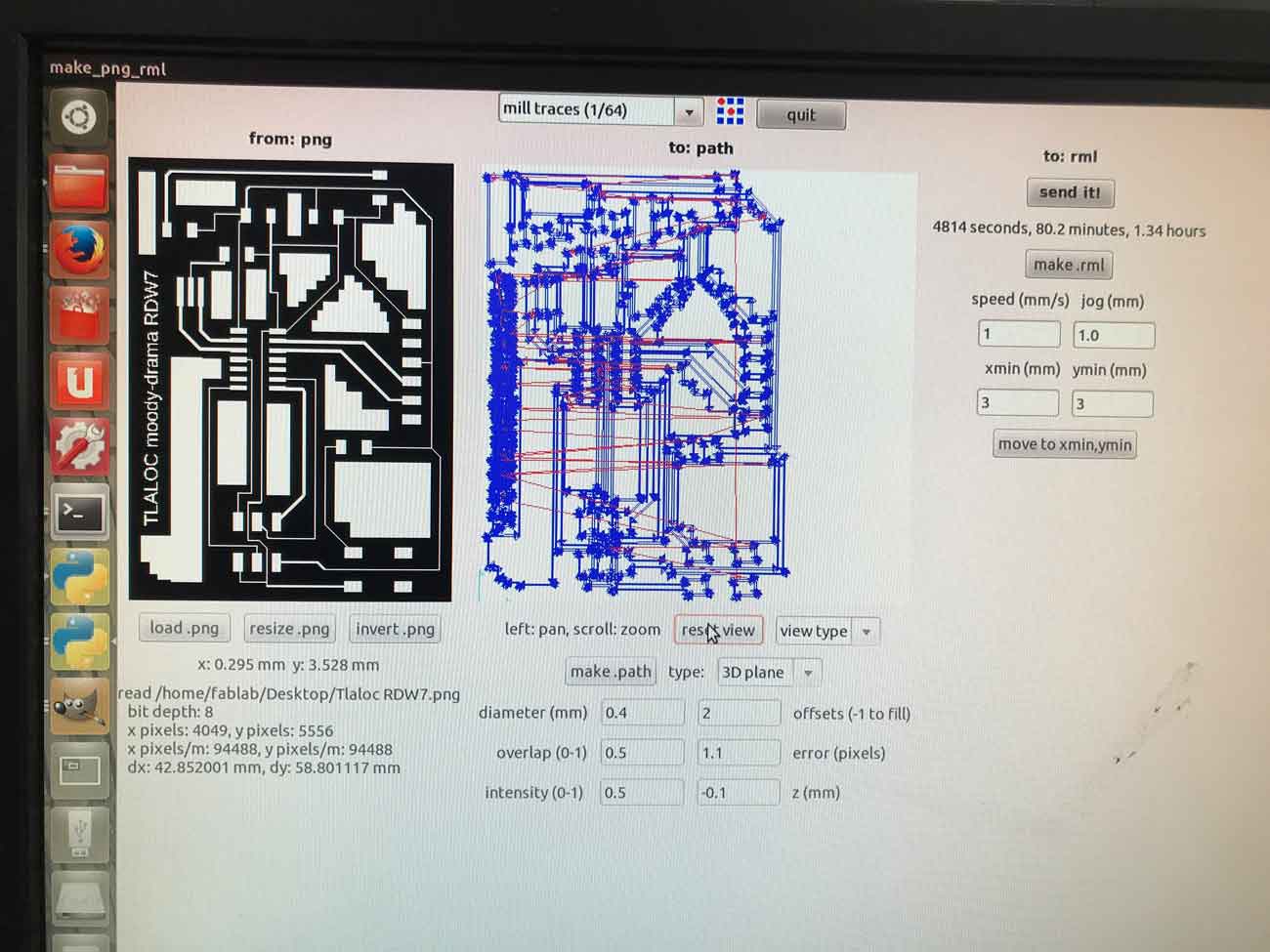
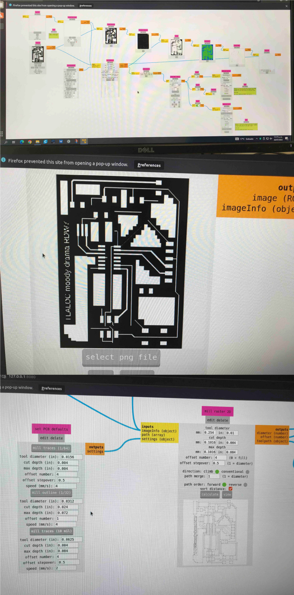
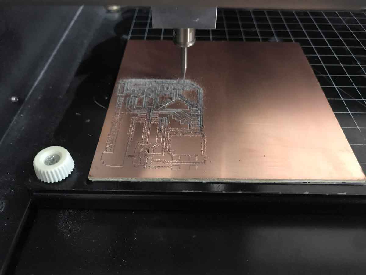
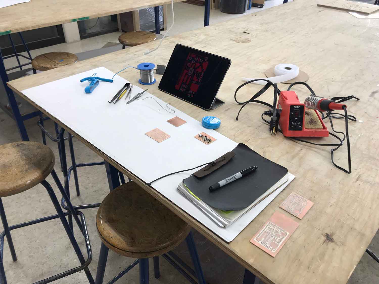
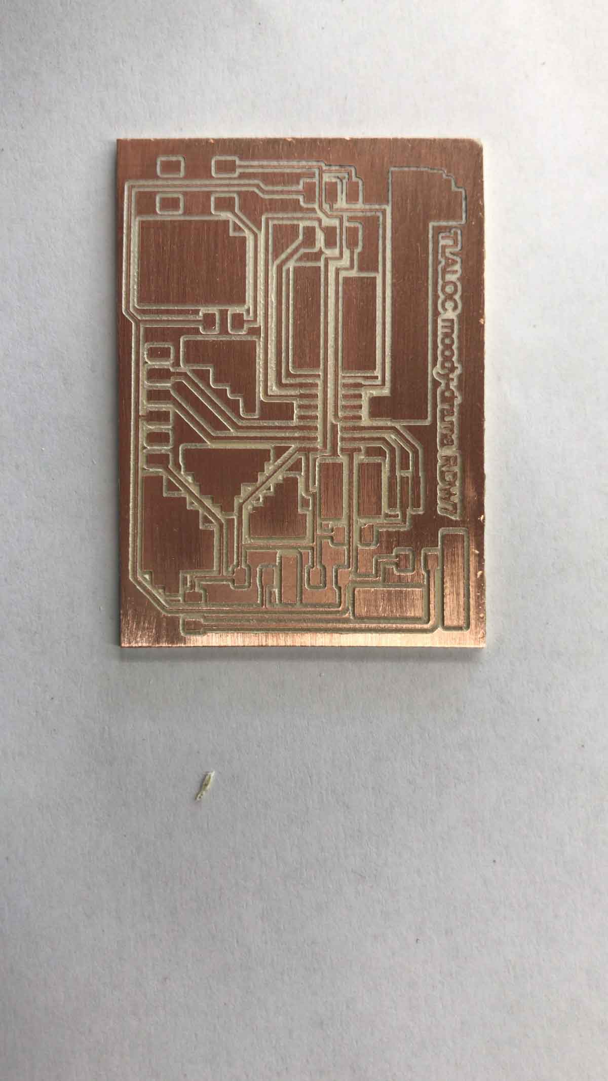
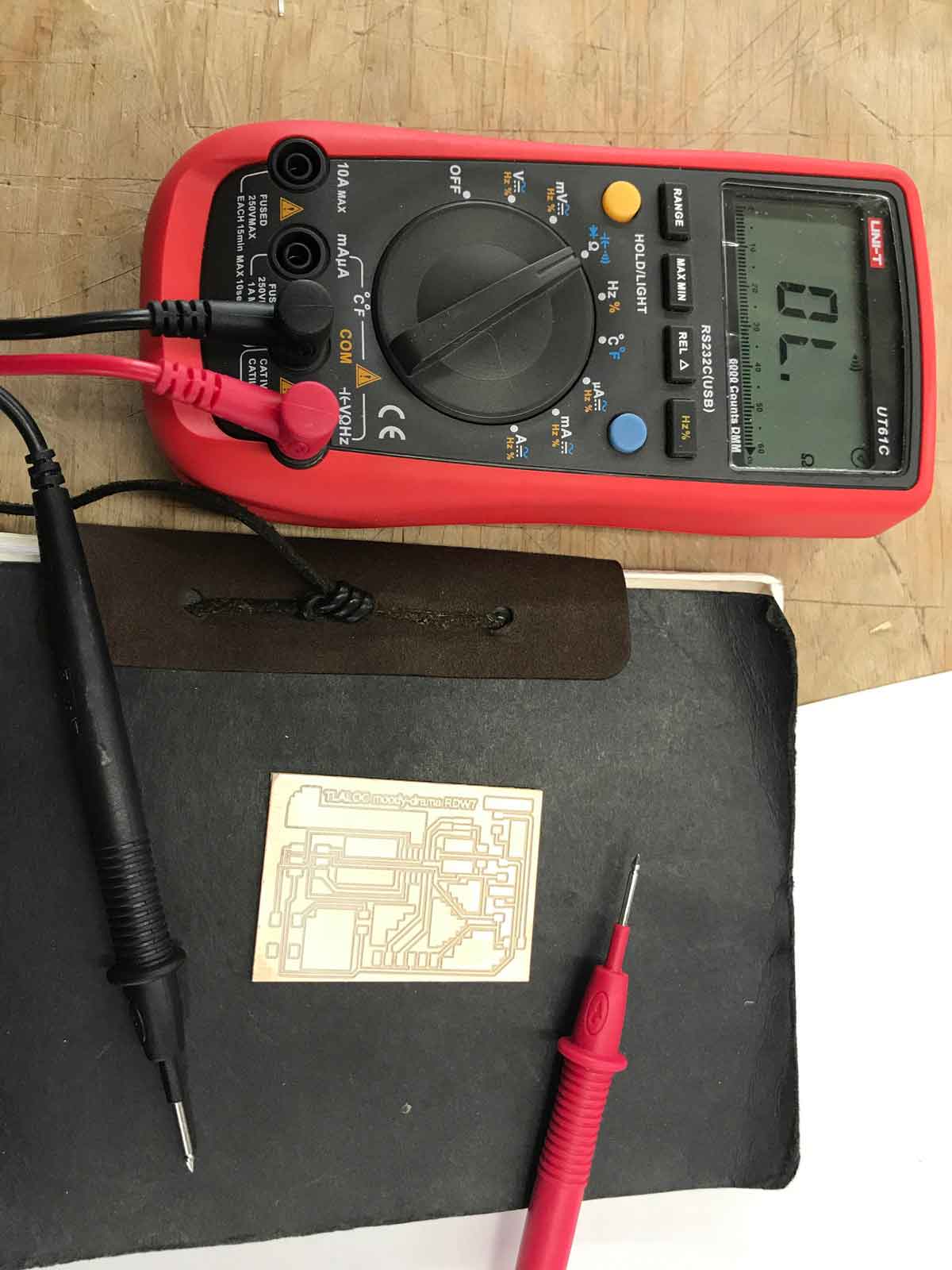
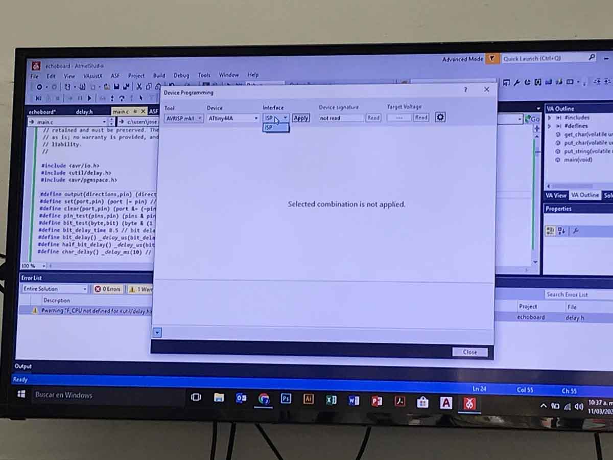
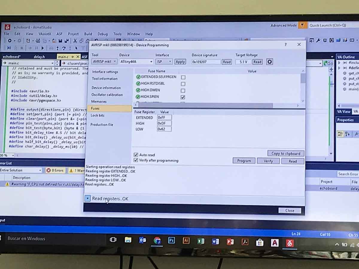
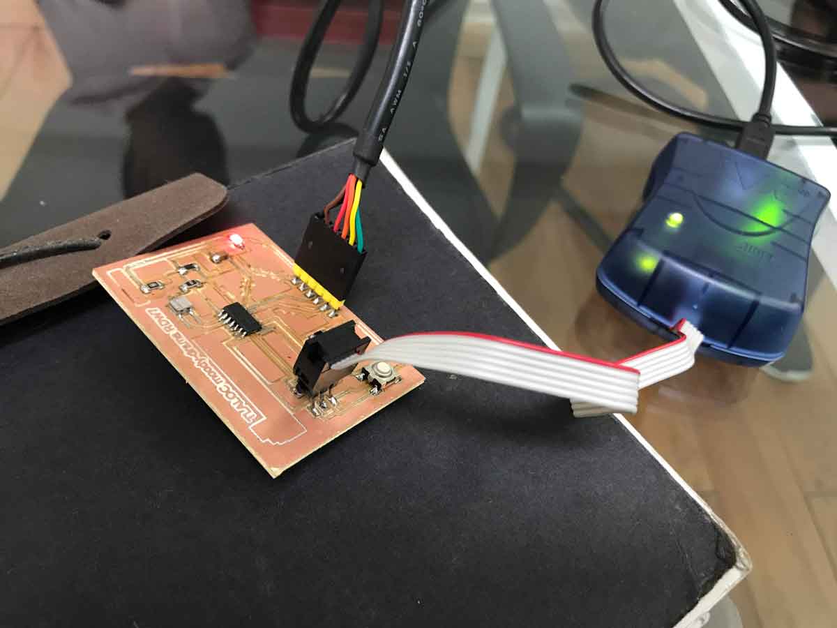
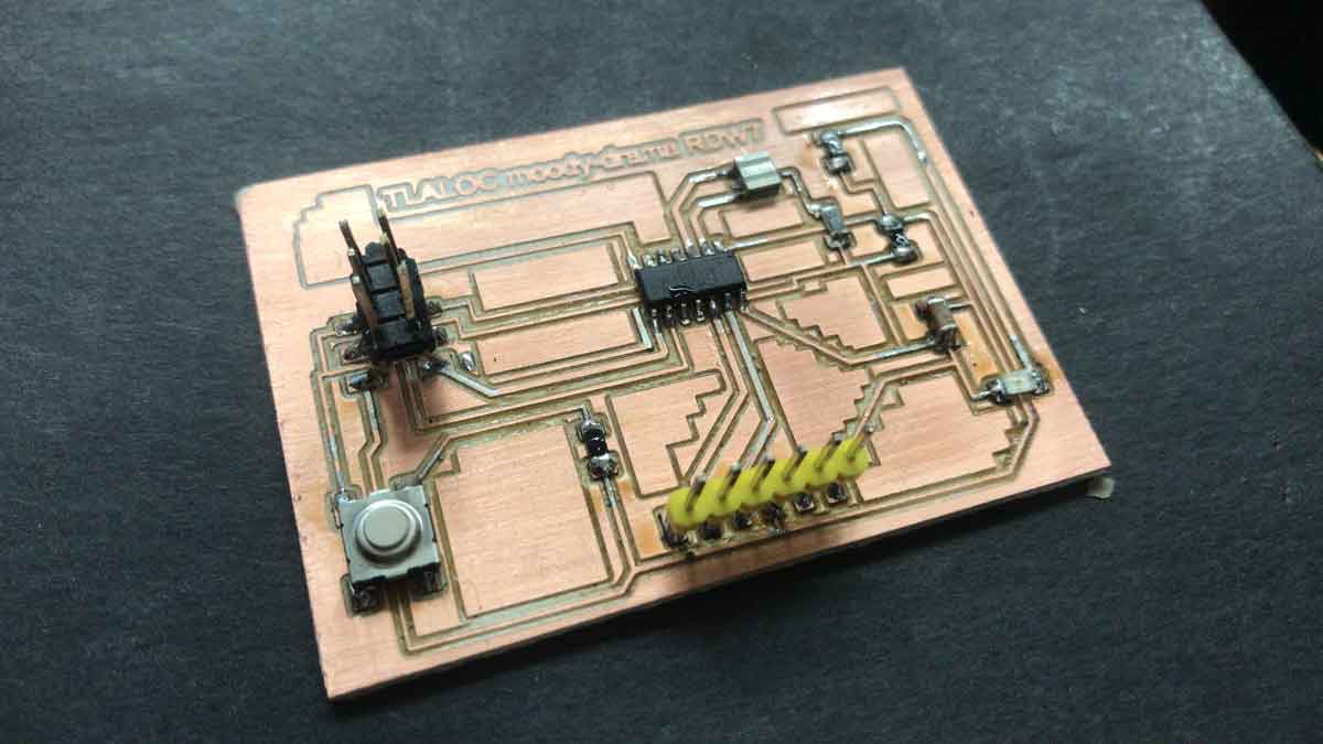
I redraw, then connect, reconnect, save like 3 or 4 differents files, then I got stuck and start to read some literature about electronics, symbols, basic electronics in google, ask for help, then I take a look to some former students to saw what they do and why, then I return to my PCB and start again from scratch, more trouble with some traces, then when I almost got it the last 2 connections between a Resistor and the GND I cant find the way to connect the trace, I ended up using a 0 Resistor , then export to PNG , monochromatic 2400dpi to Photoshop and crop it, and open it it modules, set the settings and start milling. One of the biggest issues  was the setting to "cero" in the Z axys, we unlock the drill in order to touch the copper plate and then lock it again, then change the speed to 1 mm/s and the number of offset to 2. After I got my PCB I test it with the Voltimeter and start preparing my workplace, the PCB components and start soldering; from inside to outside.


Links to the EAGLE archives of the original PCB "RDW7" and of the second one "72"

EAGLE PCB "RDW7"

EAGLE PCB "72"

and the link to the group assigment is: FabLabCDMX.


.
the schematic that we use to practice and got familiar to EAGLE. here you select and add the components that you need in your board, like resistors, leds, jumpers, etc and make the connections between those components, the connections are the green lines, you can put a label to name it and to make the connections between components using the functions that are in the tool window at the left, the green and lue lines and the AB in combination with the R2 (in black that eans that you add info above the line) and with the 10k( in black that means that you can add info below)

After that,  change the window using the SCH/BRD icon at the top horizontal menu at the right of the printing icon, and here you can see that the yellow lines connect the components that you already made in the schematic, but this a mess, the yellow lines are everywhere and some are crossing between them, we need to clean this. To start with this, we can use the "autoroute" , this function connect the components in the best possible way but at the end you need to make some manual adjustments
In this example, you can see that the yellow lines now appear in red, this are the traces that connect the components and are the "lines" that the milling machine will do, the rectangles are the places where we are going to weld the components to the board. Now returning to the traces , yo can see that here they are in different thickness between 6 and 20, milling a slim trace requires much more detail and precision than a thicker one like 20, if you can use 20 in your board design is better.
Here is the autoroute window mention aboved
The autoroute option start working in different options to connect the components in an optimal way.
In this example, when you are ready to mill you need to export the design into a .PNG image, here are the export settings, it is recommend that use a 1200-1500dpi resolution, in monochrome mode and in the Area select window, that means that your going to export just the part of the window that we are looking at. Also, you must hide al the layers and just make visible the one that you are going to export, in this case the top that has the traces and later the 2nd one that has the outline.
I added the logo in Photoshop
When in Modules ready to mill we just found that something is wrong in the design, The traces that goes just between the paths of the IC looks wrong: the paths 3&4 are like if they are just one, the milling machine can´t do this and the trace are going to break, so, I had to start again with the schematic and look other ways to connect the components.
So it`s time to start again from the Schematic
Now the Switch, Led and resistor are connected and, since the switch is the one that goes to GND is a PullUp and the resistor I use for the LED is a 1 kohm

Almost done
Ready to export the .PNG file
The PNG looks like this
Now the "make path" looks good. In 2020 we use "modules" to make the last settings before milling. We don´t have anymore Modules neither that computer, but now in 2022 we use MODS, you can see this in later assignments but i think is good to left this assignment like this as an example of what we use to had.
Here´s the Toolpath create in MODS to mill the PCB, in the section "mill traces" I change the dimension to 0.0625 in the "tool diameter (in)" box because we use a tool of 1/16

A zoom image of the milling process
In the meanwhile I start to prepare my workspace in order to weld my PCB.
Here is the PCB before starting to weld the components in it.
Cheking the current flow between traces to see if there´s some broken traces, but everything is fine.
I´m going to start welding the ATTiny44 it´s the more difficult component to weld, and also is almost in the center, it´s prefer to start welding from the inner to the outer of the board.
The final PCB with all the components in it
Then we need to test the button and the make the LED on and off, but to do that we have to program the board to do that using an AVR and some code to run the program that makes the led on and of; High and Low. For this we used the "hello.ftdi.44.echo.c" program that we download from the "Embedded Programming" Fab Academy Schedule page / ATtiny44 echo.c link and then used the AVRStudio software to flash the board.
the code that we are going to use that is in the fab academy web page.
Select the ATtiny 44A of the list, that´s the one that is in my board

Making some previous setup of the AVR to communicate with  my board
The fuses are the same as the ones from the factory, we don´t change anything.
Connecting to the AVR
1
The Led is On
My "Hero Shot" of the board

.


the green spot

a place to re-connect