remember the Gantt
chart from "project Management"? well, this is the status of the
assignments and the Final project
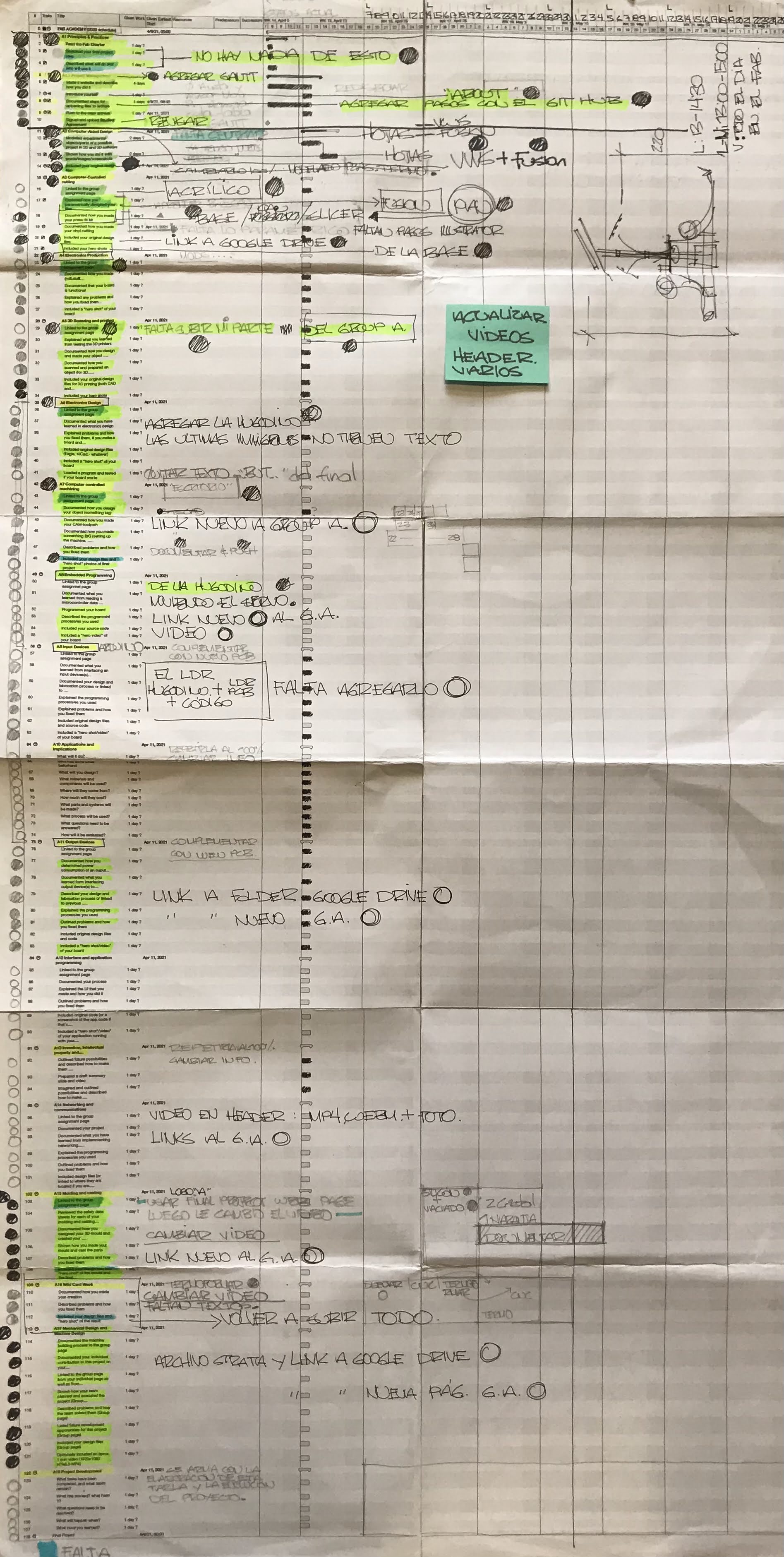
And specifically
for the final project, I made and print a new diagram with my To
Do´s based on the Nuevall and the Schedule CheckList
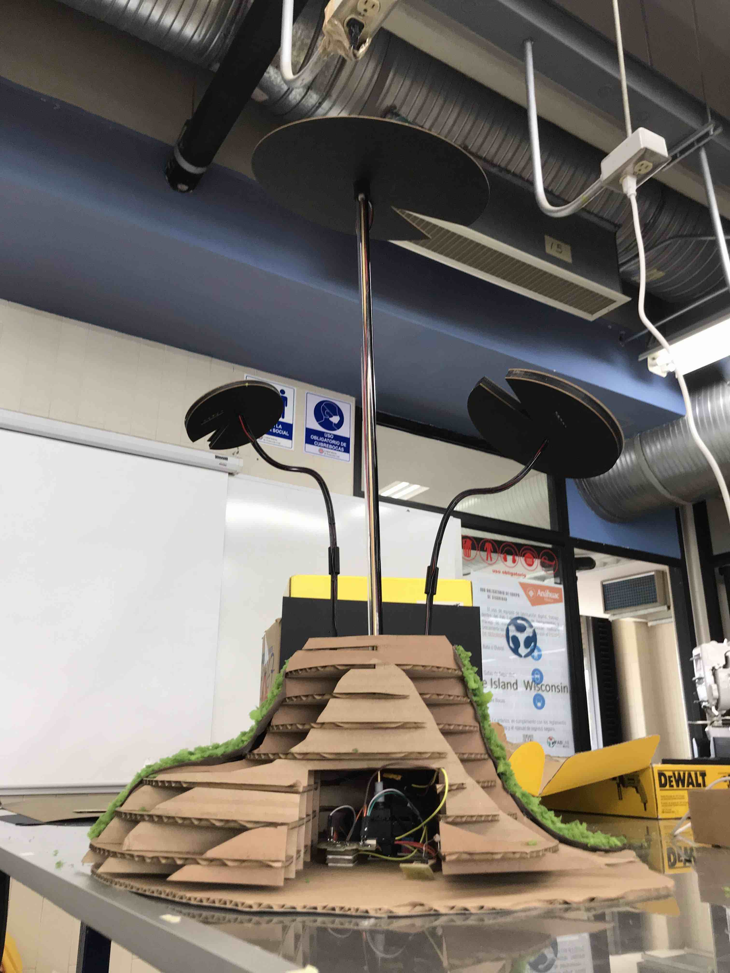
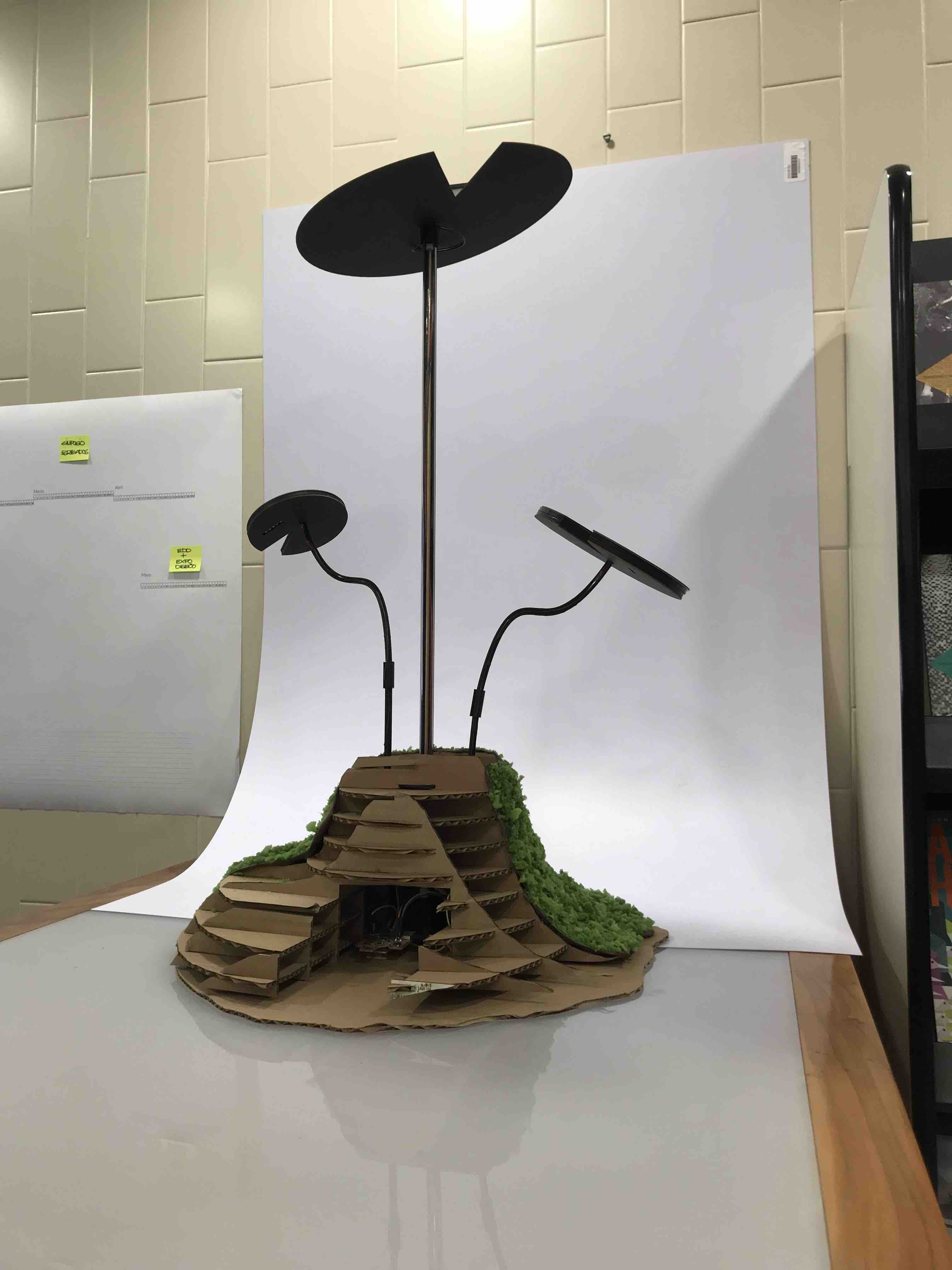
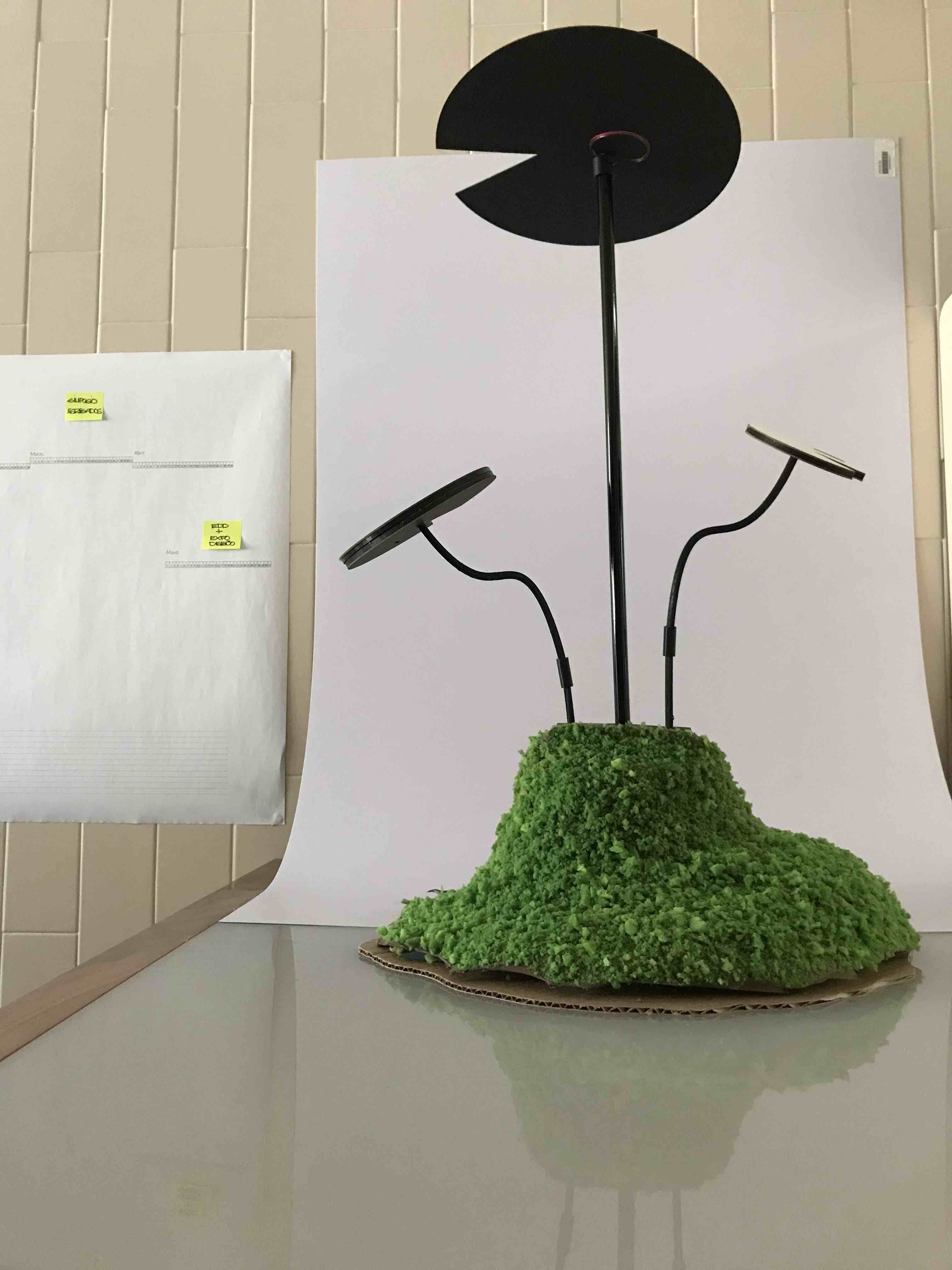
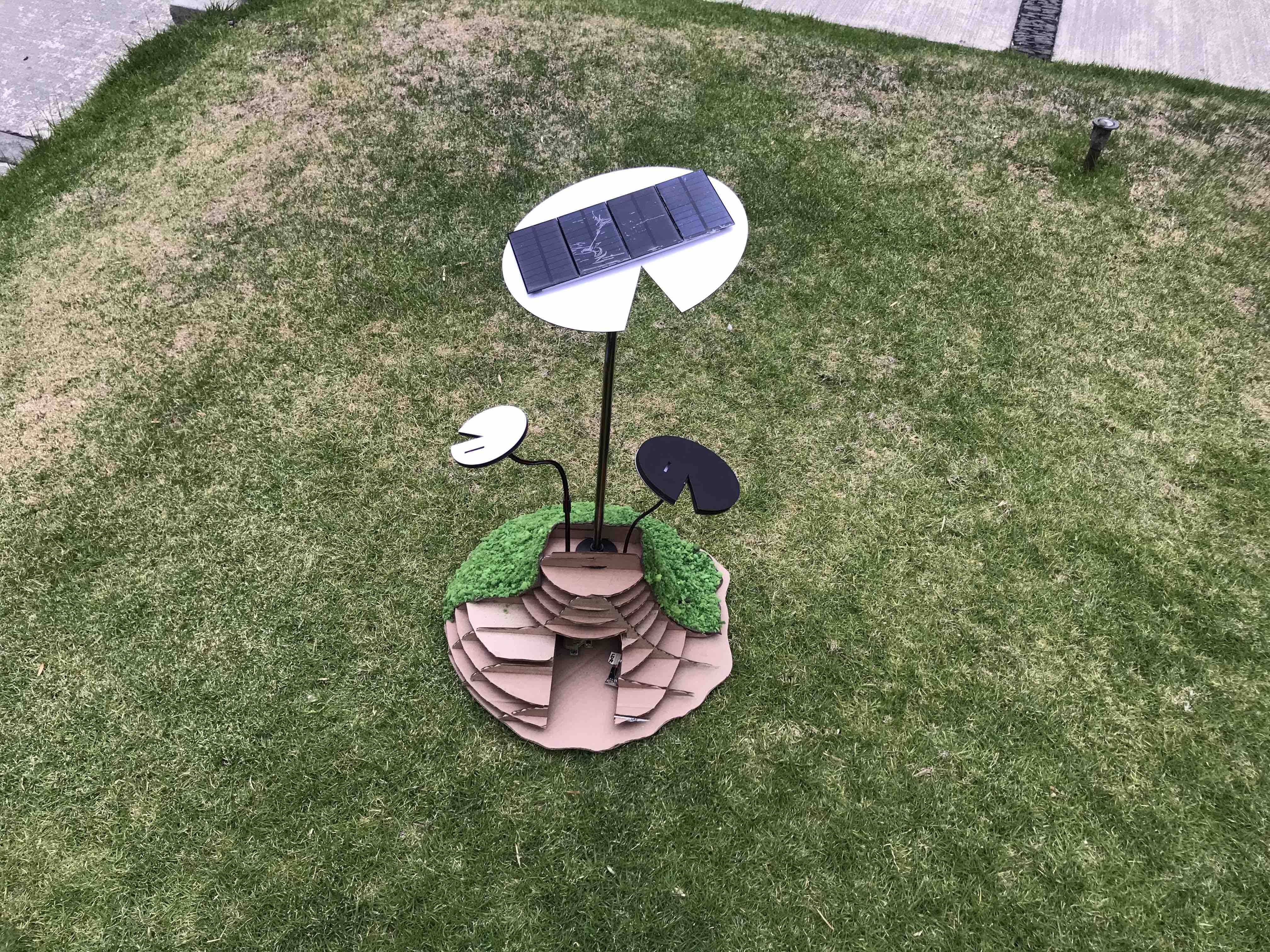
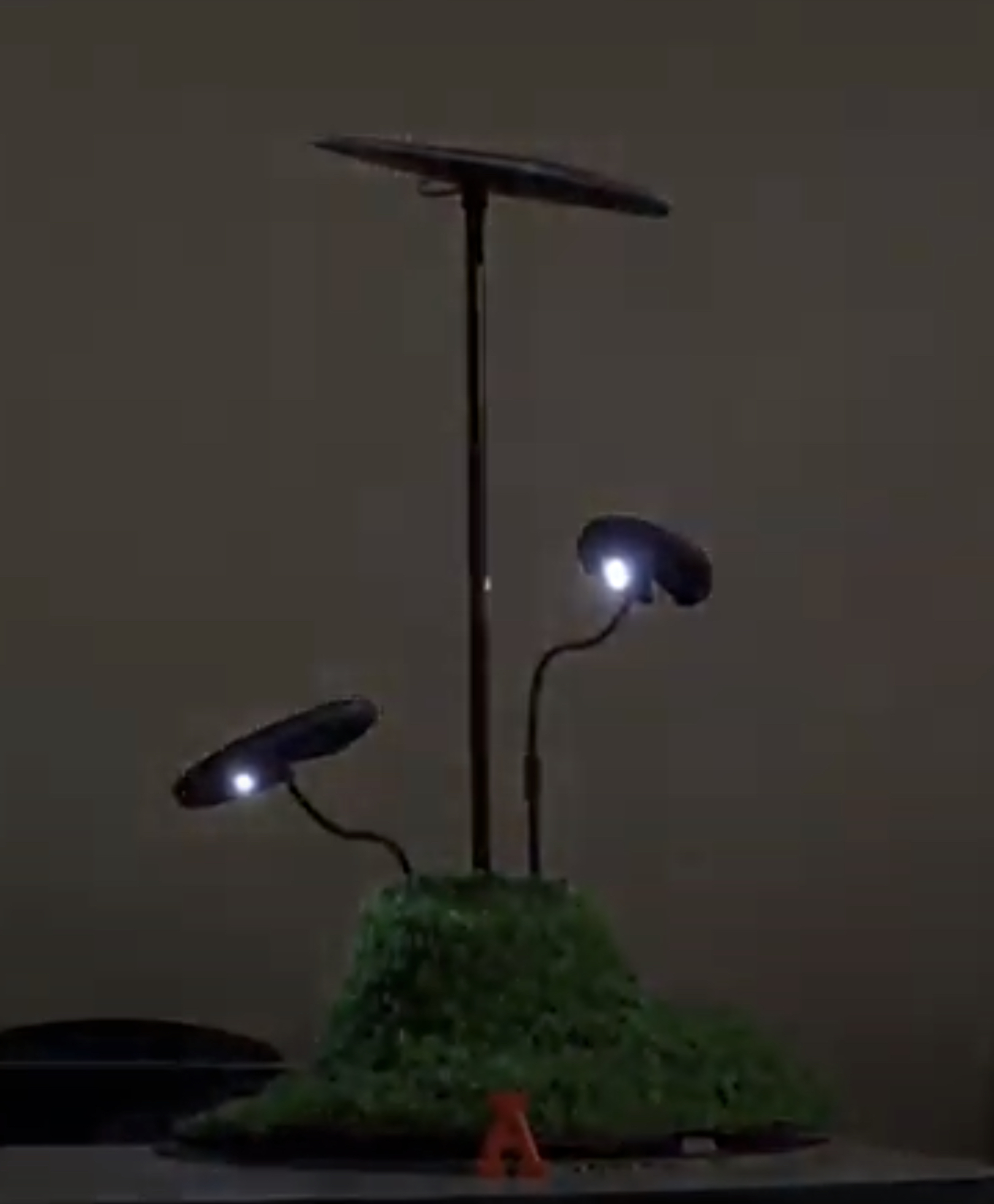
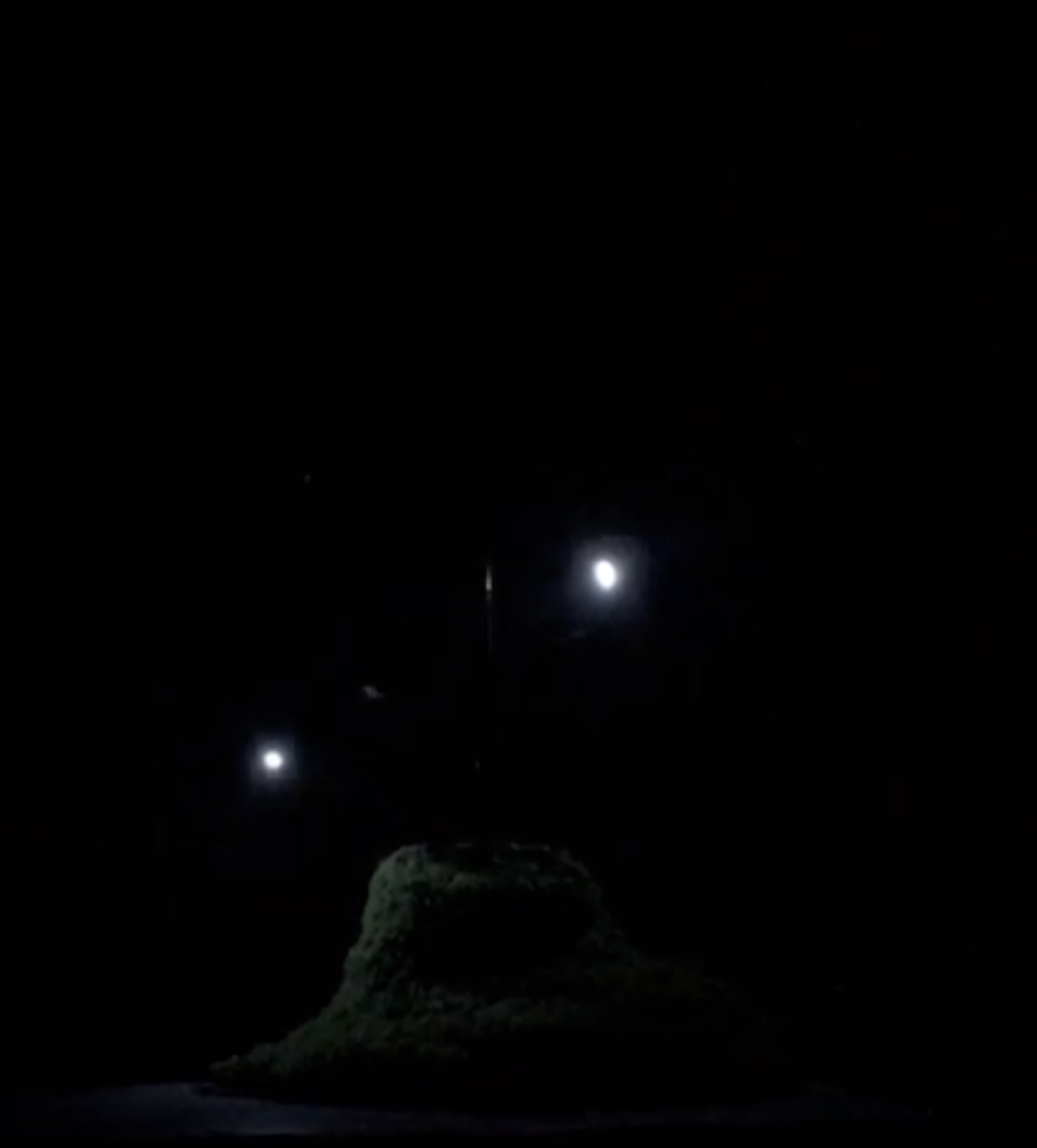
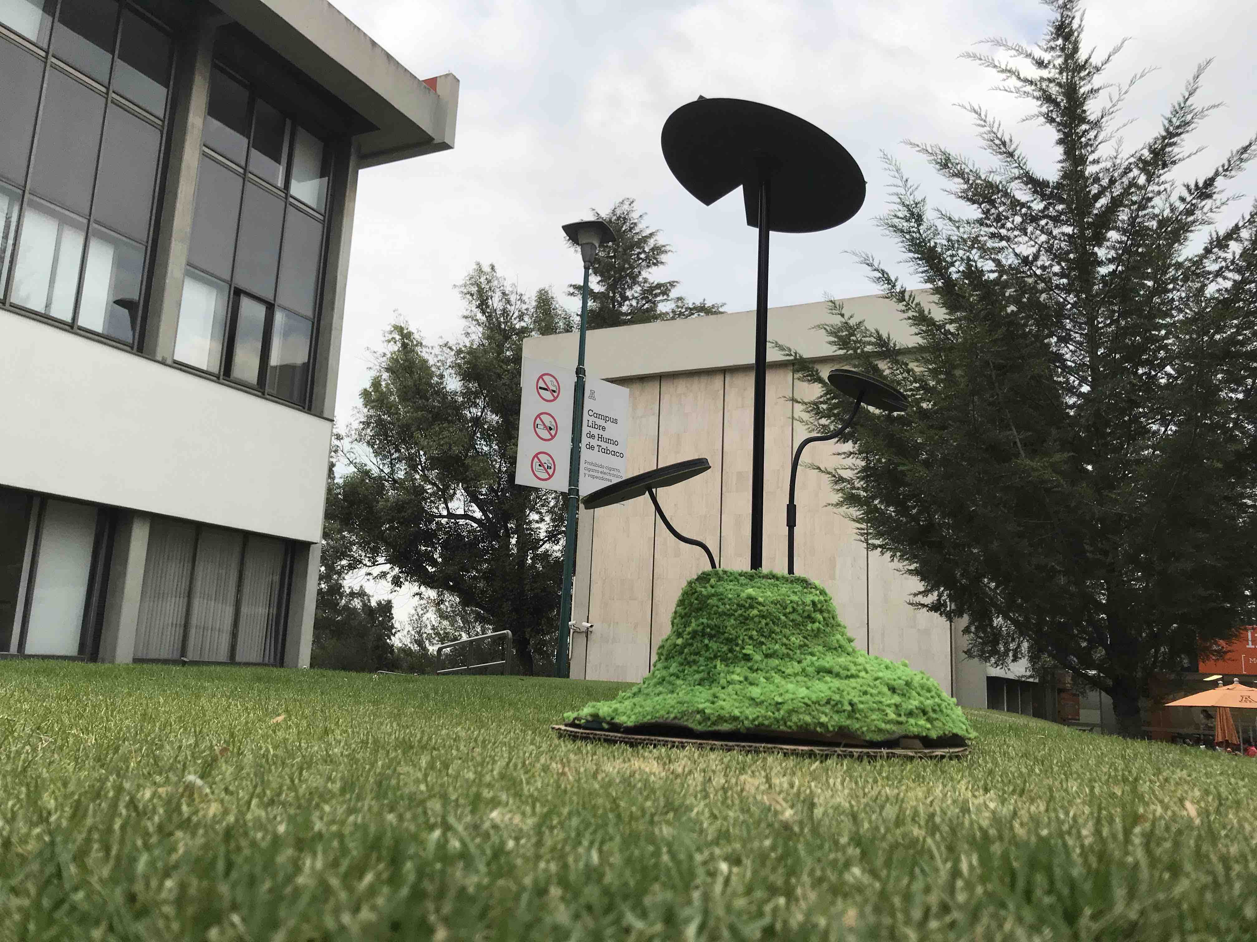
initial stages of the green spot
a place to re-connect
What tasks have been completed, and what tasks remain?
I already had my Final Project idea
and design but it remains the final shape of the base and to
scale the original design, also to fit the internal components
like the servo, the batteries, etc into the base
I already test the SAMD code in the Arduino IDE to move my servo and now I´m modyfing the code to position the servo in the right angle and with the delays like the time spend in that position during the day.
I have some 2d and 3d designs to be cut in the laser machine and to be print in the 3D printer.
I have aditional boards, like the LDR one
It remain to put in the same code the servo and the LDR that turns on and off the LEDS.
Also, it remain the assemble of the
hole project, at this point I just made individual tests of the
different components.
What has worked, what
hasn´t?
The new board works fine but the
drawing in rhino and the scale in Slicer it´s not the same when
you import the document, we need to fix this in order to laser
cut the base.
What questions need to be resolved?
the solar panels charge the 4pack of batteries?
The servo rotate the axis of the principal leaf when all the components where fit in place?
The length of the brass rod and of
the acrylic tube to fit in the base and into the assemble
component of the servo?
What will happen then?
Everything is model in fusion, so i
can know in advance the lengths, and where the components fix,
but when you have all the pieces in person we can be sure if
everything goes well or maybe need some adjustments.
What have you learned?
That the assignments build together the final project, and if I know what´s going to be my final project I could work in the components of my final project from the beggining, but I change my mind so many times, and it was because the lockdown comes just right when we where starting the Academy and resume the activities in the labalmost 2 years later.
but I learned so great things about
programming, electronics,new software like fusion360 and
how everything is connected.
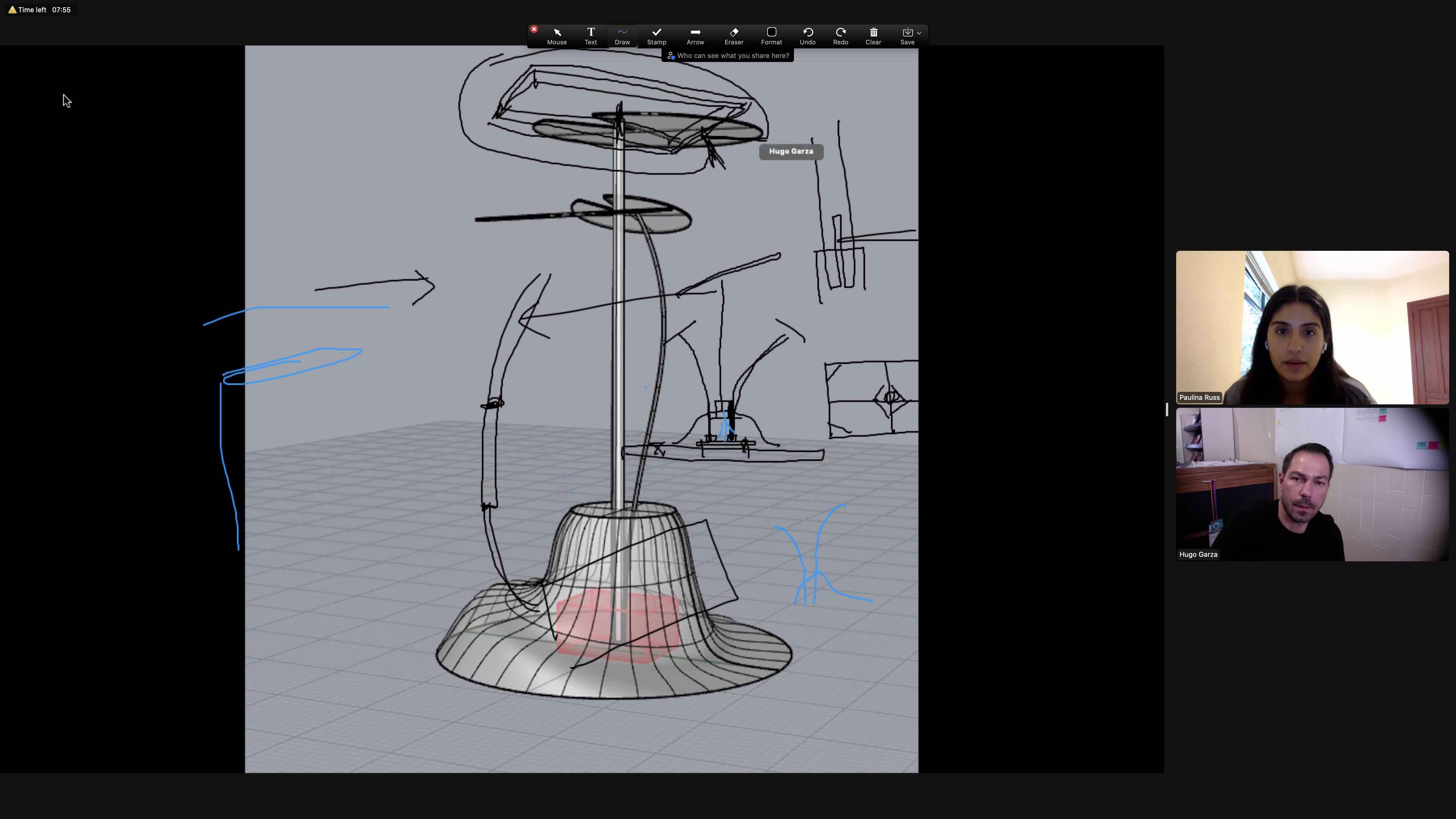
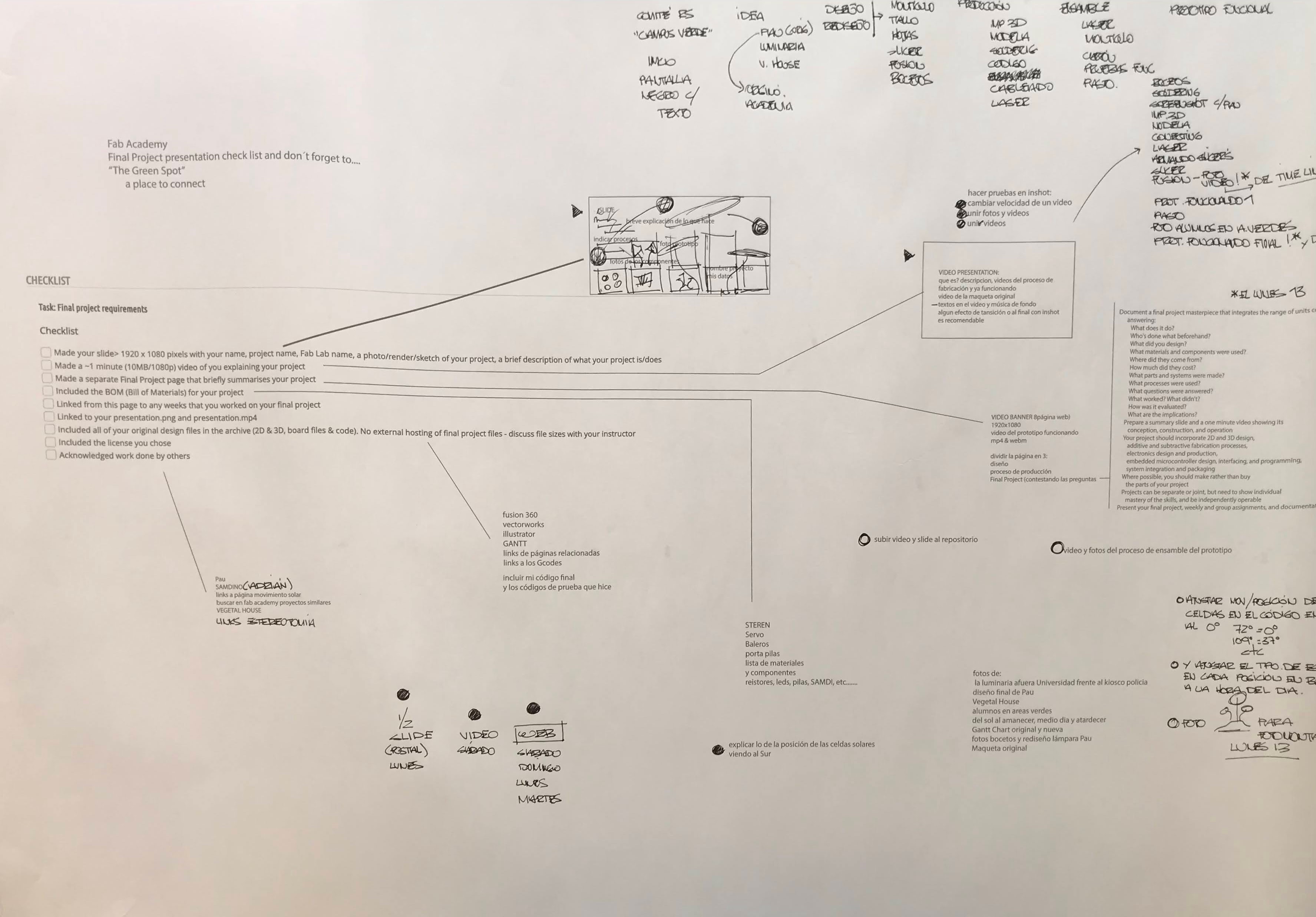
She is Paulina. Here we
are sketching the new components of the green spot over a 3d image
so she can redesign the base and I can continue with the design of
the new components.
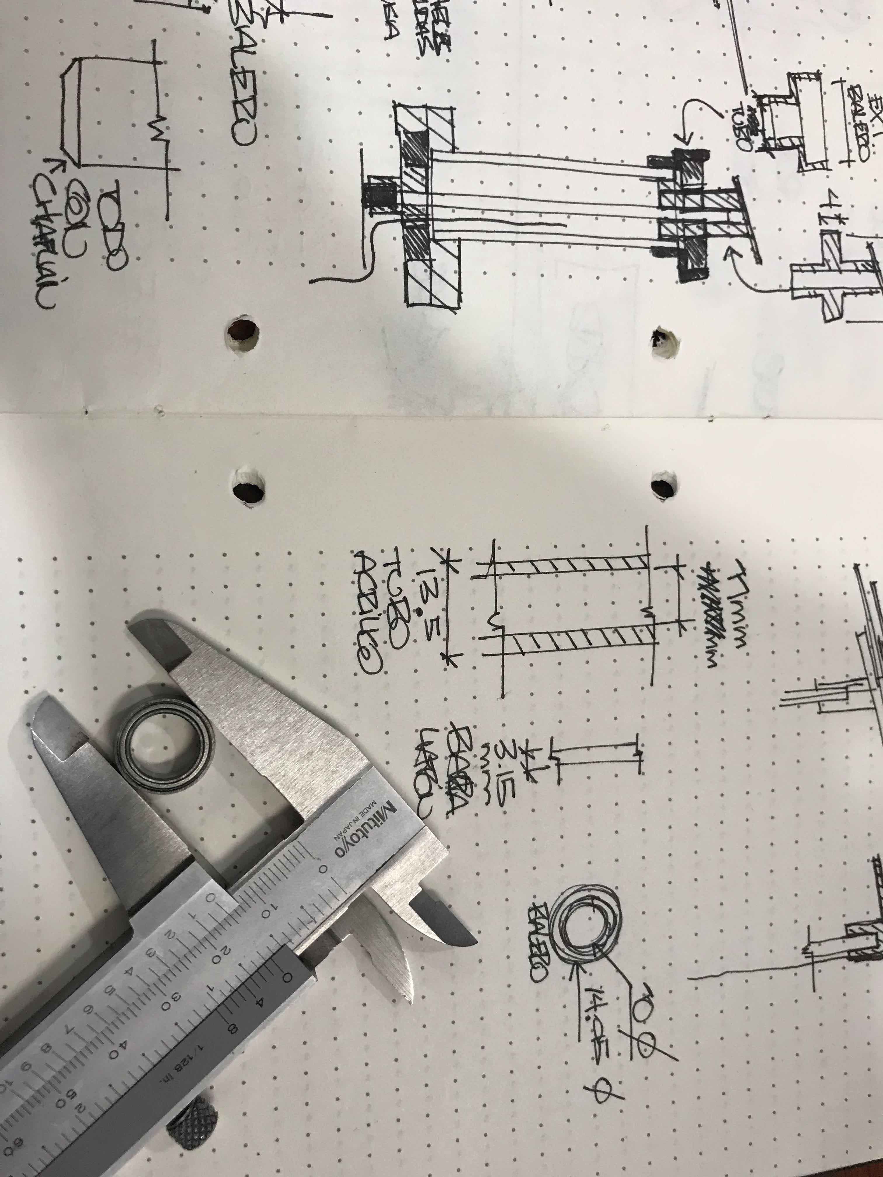
Measuring the
bearings so I can start filling the Parametrycs in fusion360
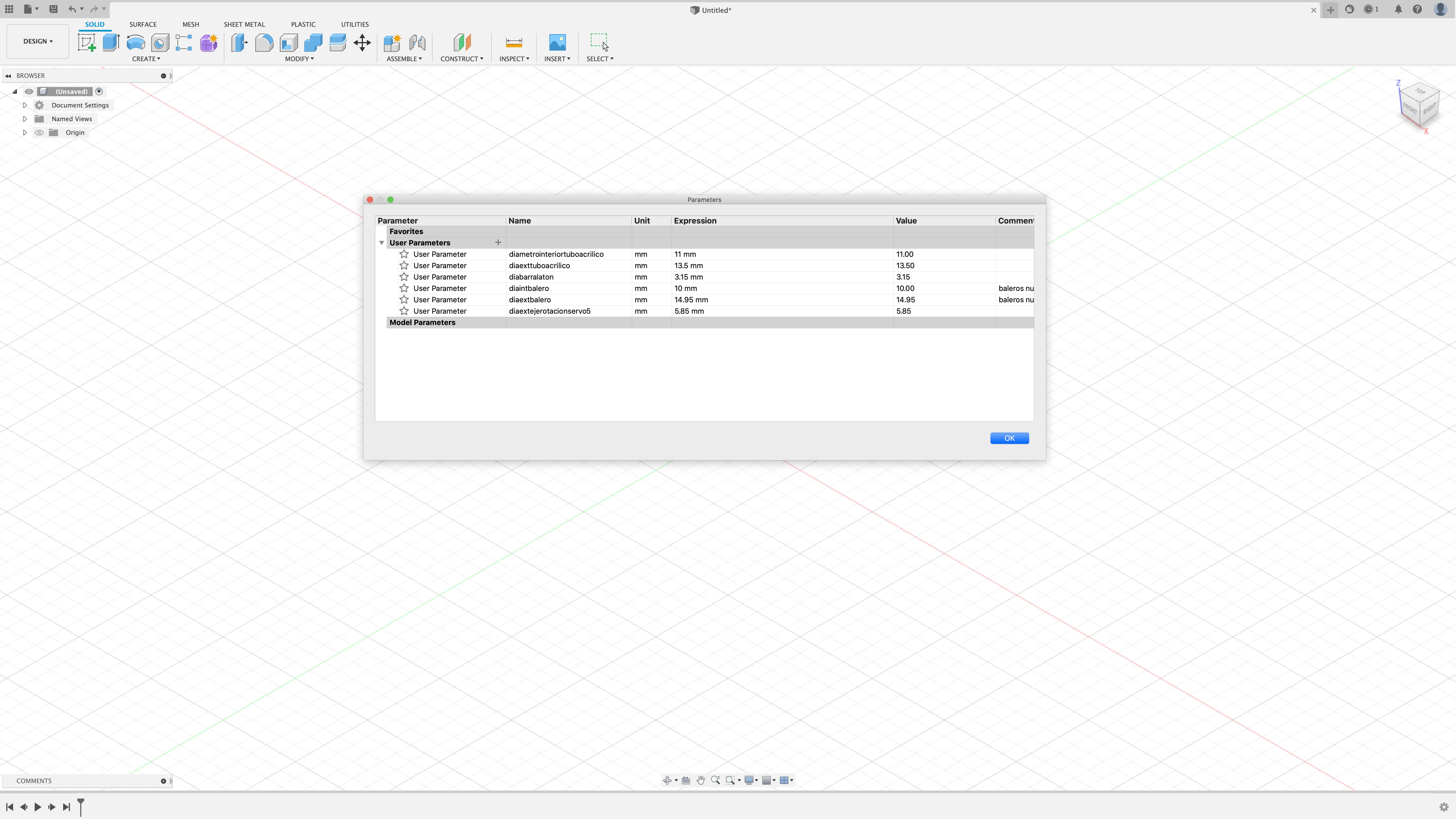
Some parametrycs that
I fill in the table, here you can name it and give them an "X"
value or an expression in dimesnions, here I use mm.
I want to fit
this components into the base, so here I made some drawings
in the image to show it to Paulina so I can explain better
my idea and wich components to fit in.
investigation
a place to re-connect
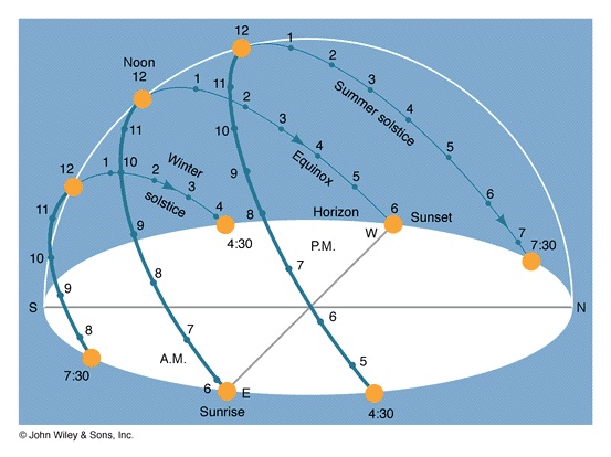
position of the
sun
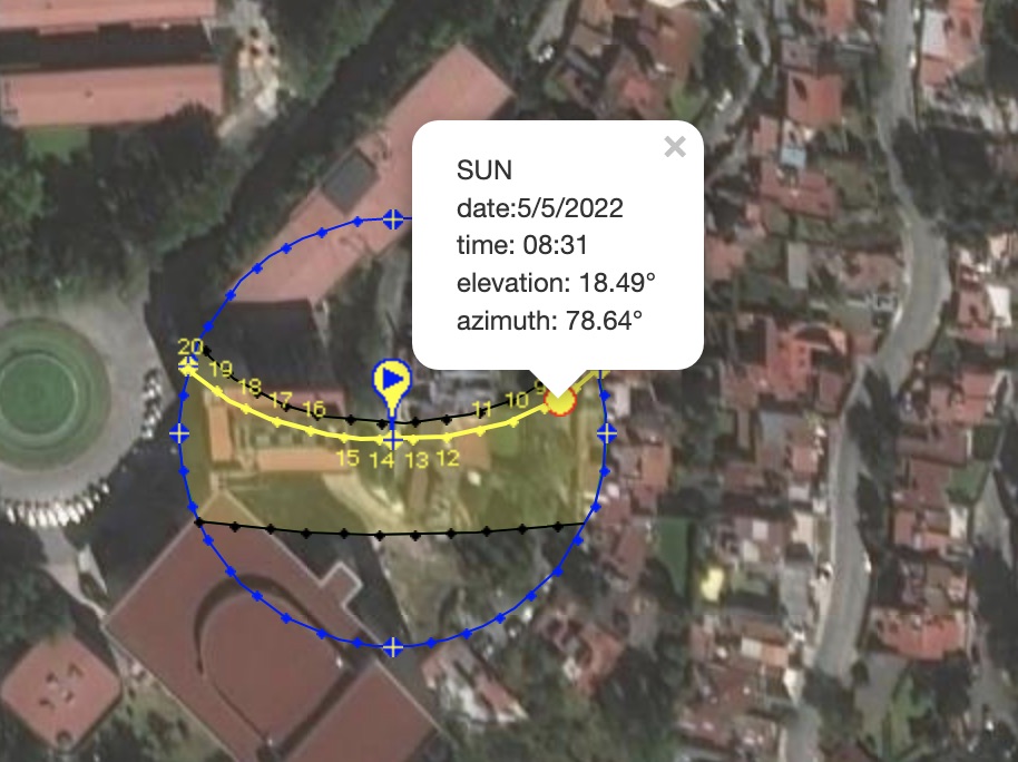
Path of the sun
here in the Universidad Anáhuac México
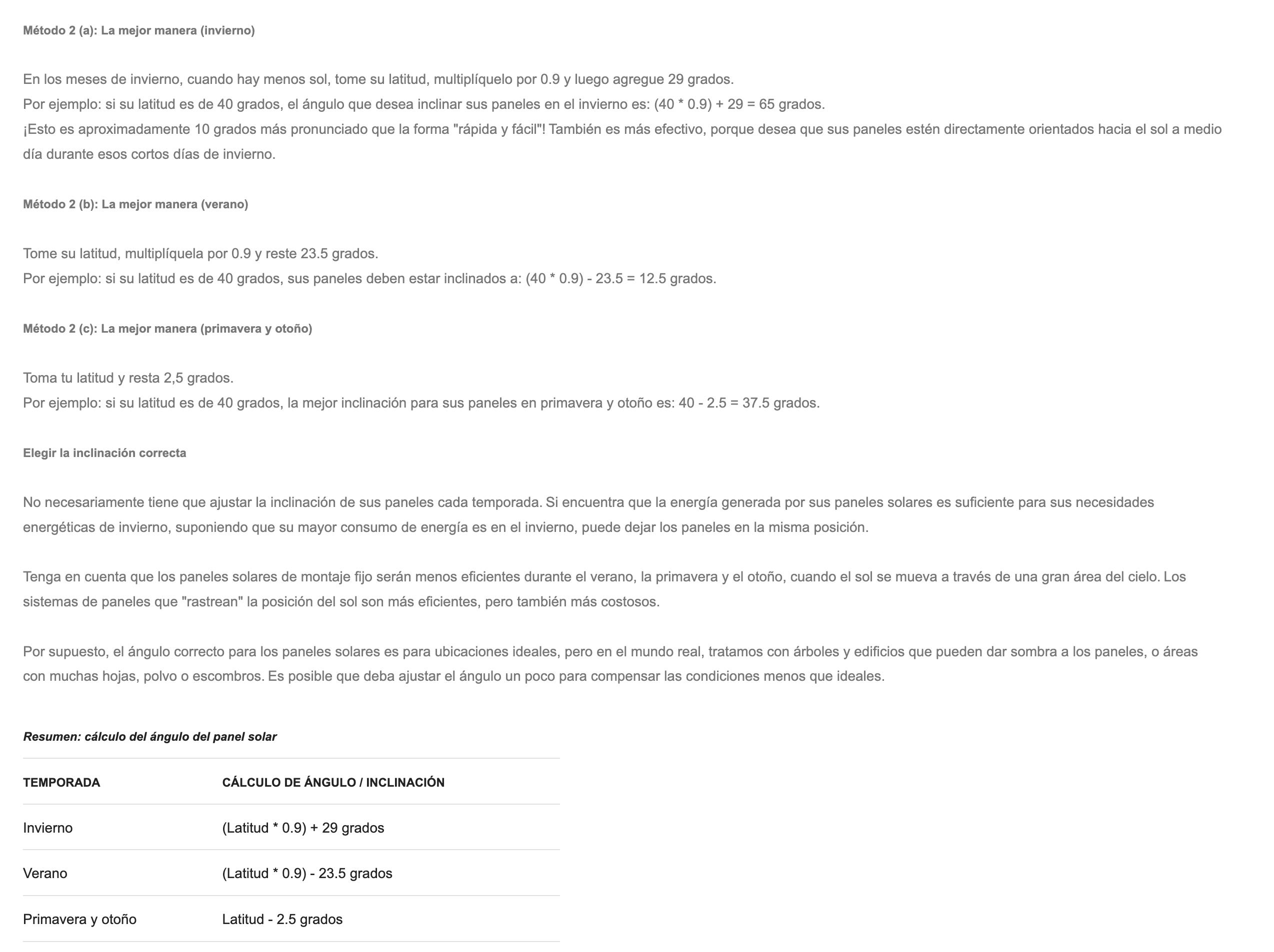
Different methods
to choose the right angle to set up your solar panels
path of the sun
in summer and during winter

the incline I
choose for my panels is 16.9º
production
a place to re-connect
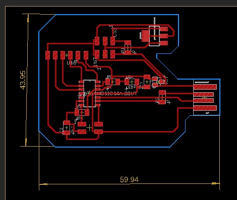
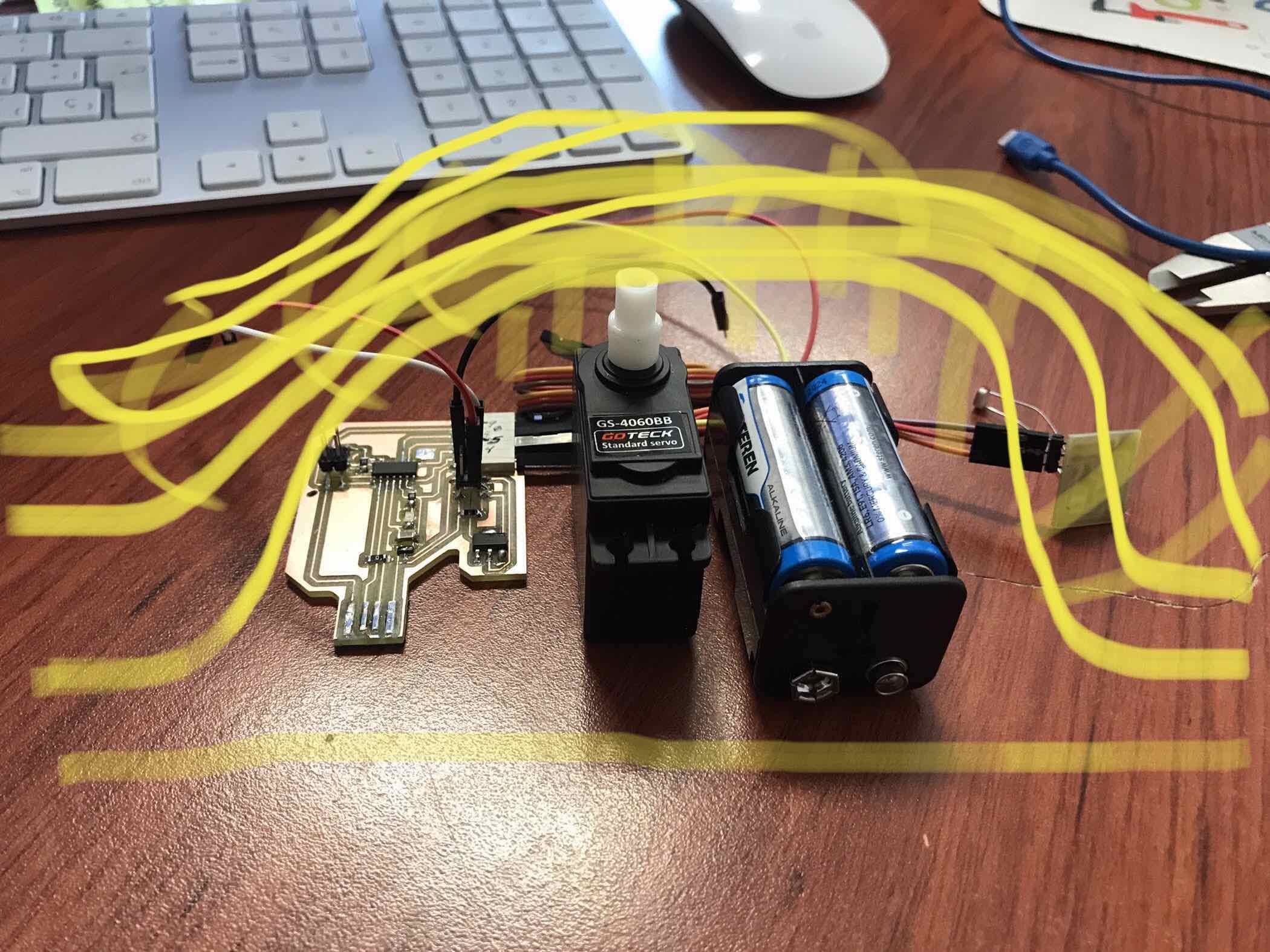
Image of the PCB
with components and traces ready to export it to a PNG image
My redesign of the
SAMDINO, the Hugodino, this PCB its the one who´s going to
control my project
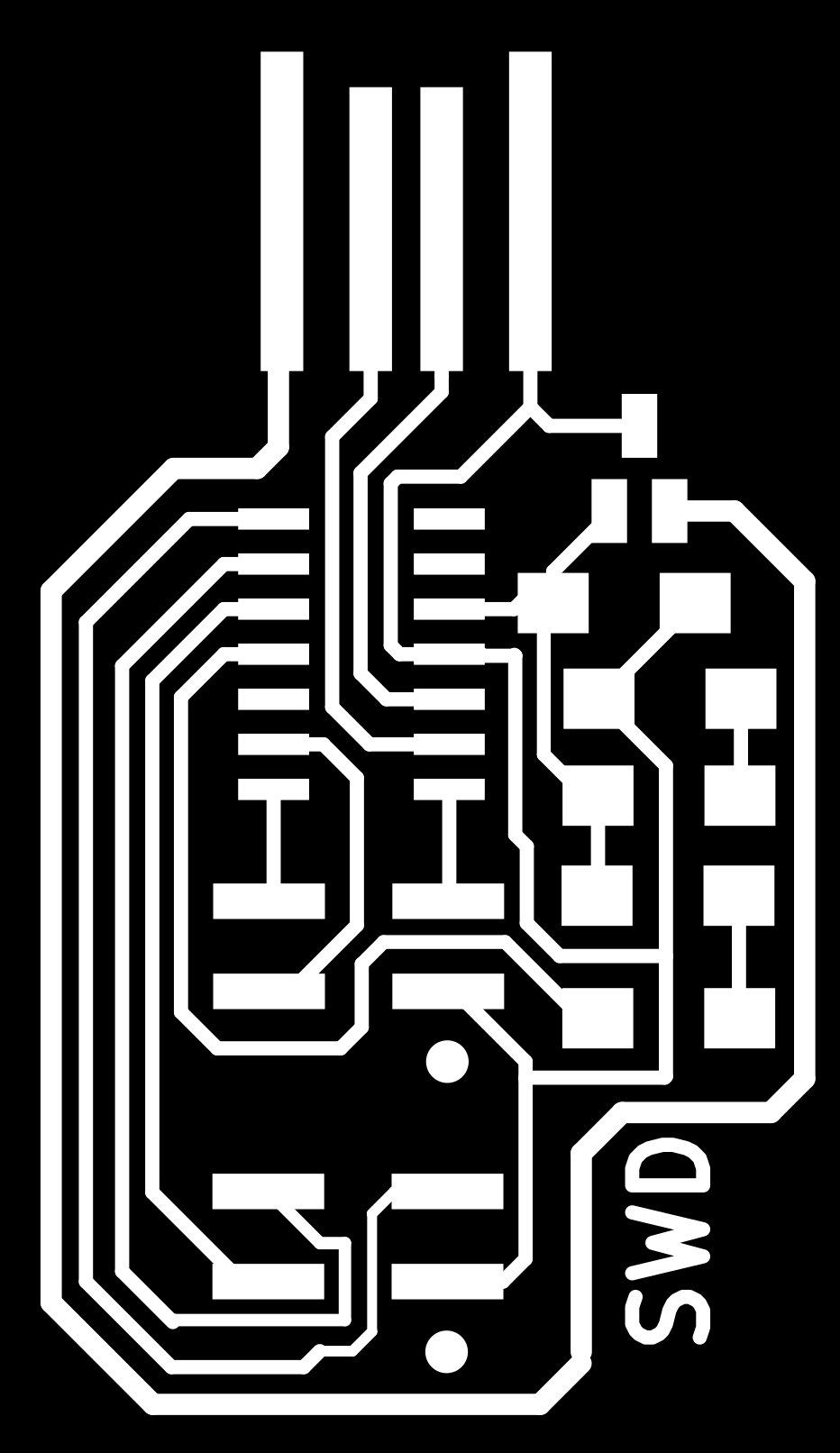
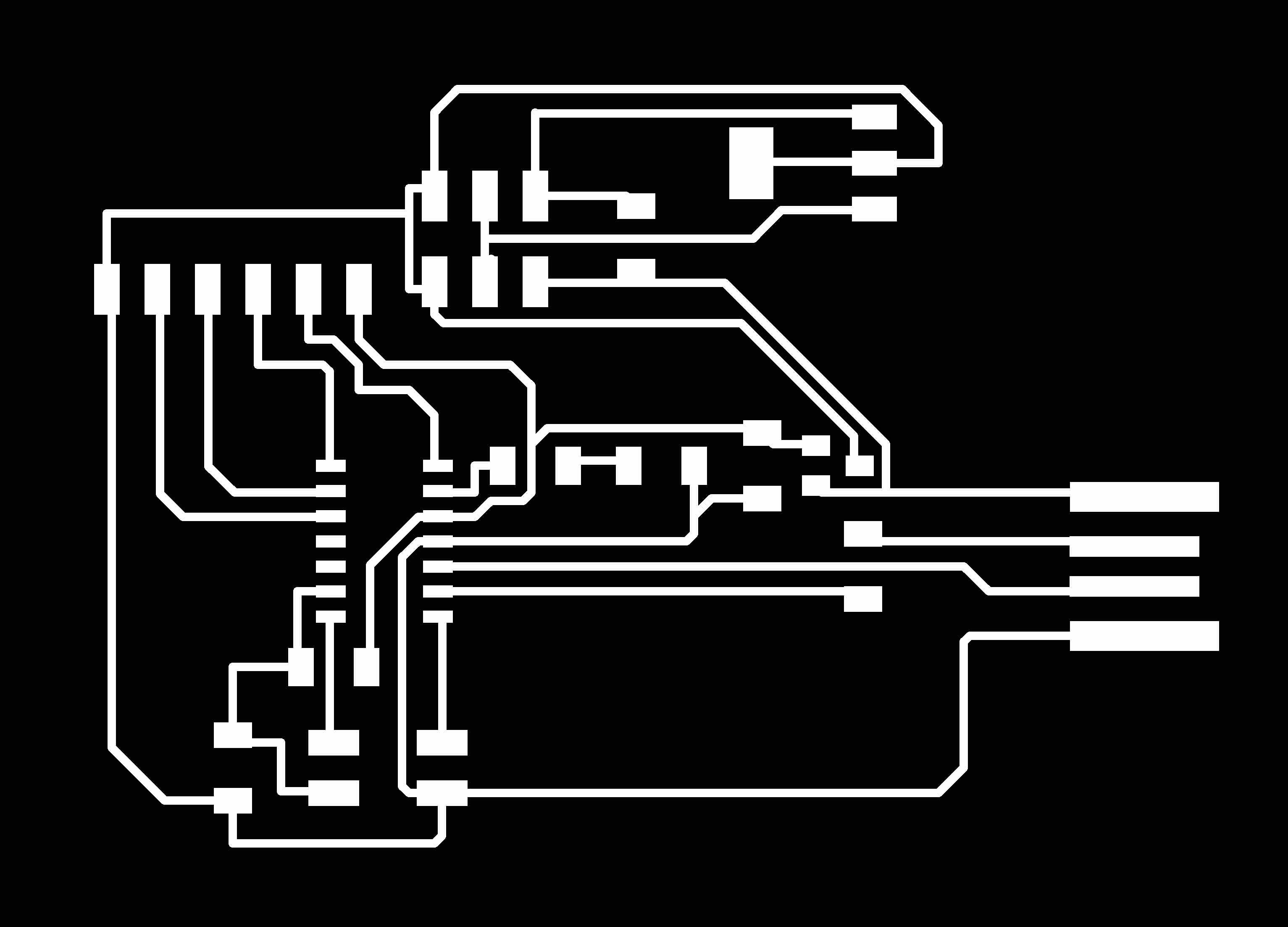
PNG image of my SWD
PCB
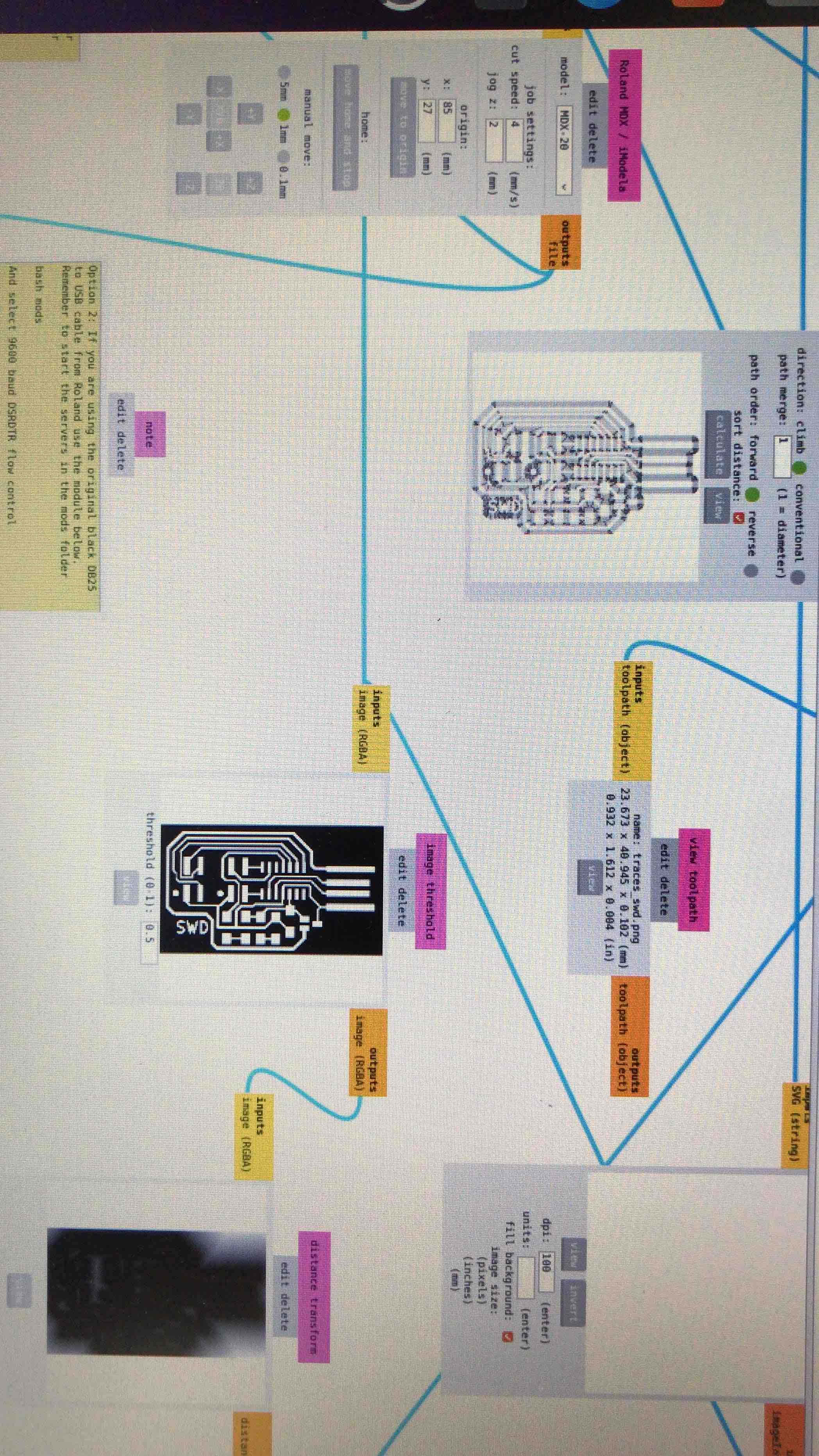
The PNG image of my
PCB, always import a PNG image of the PCB and of the outline if
need it
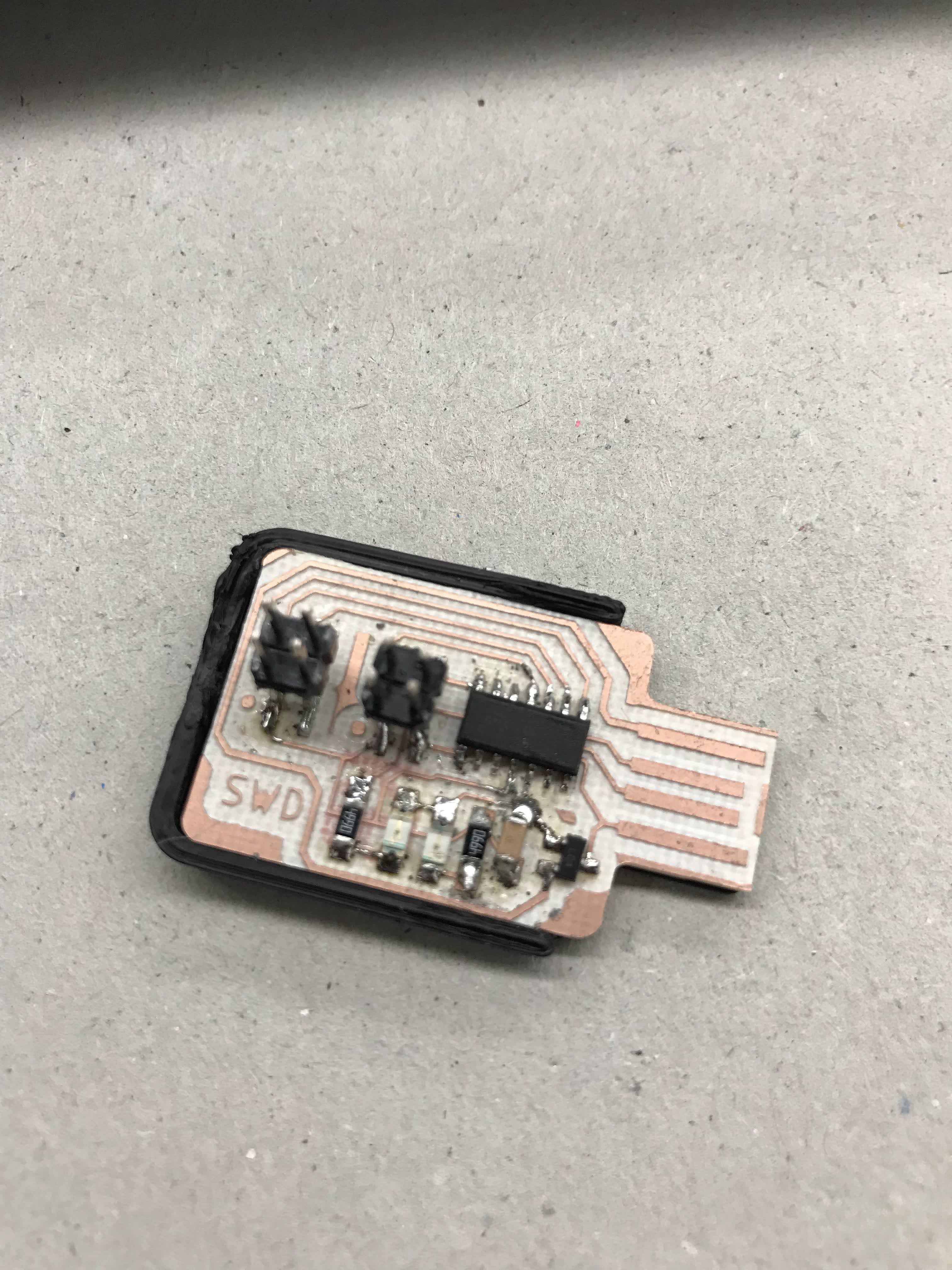
A shot of the SWD
finish, with this I will program my Hugodino board
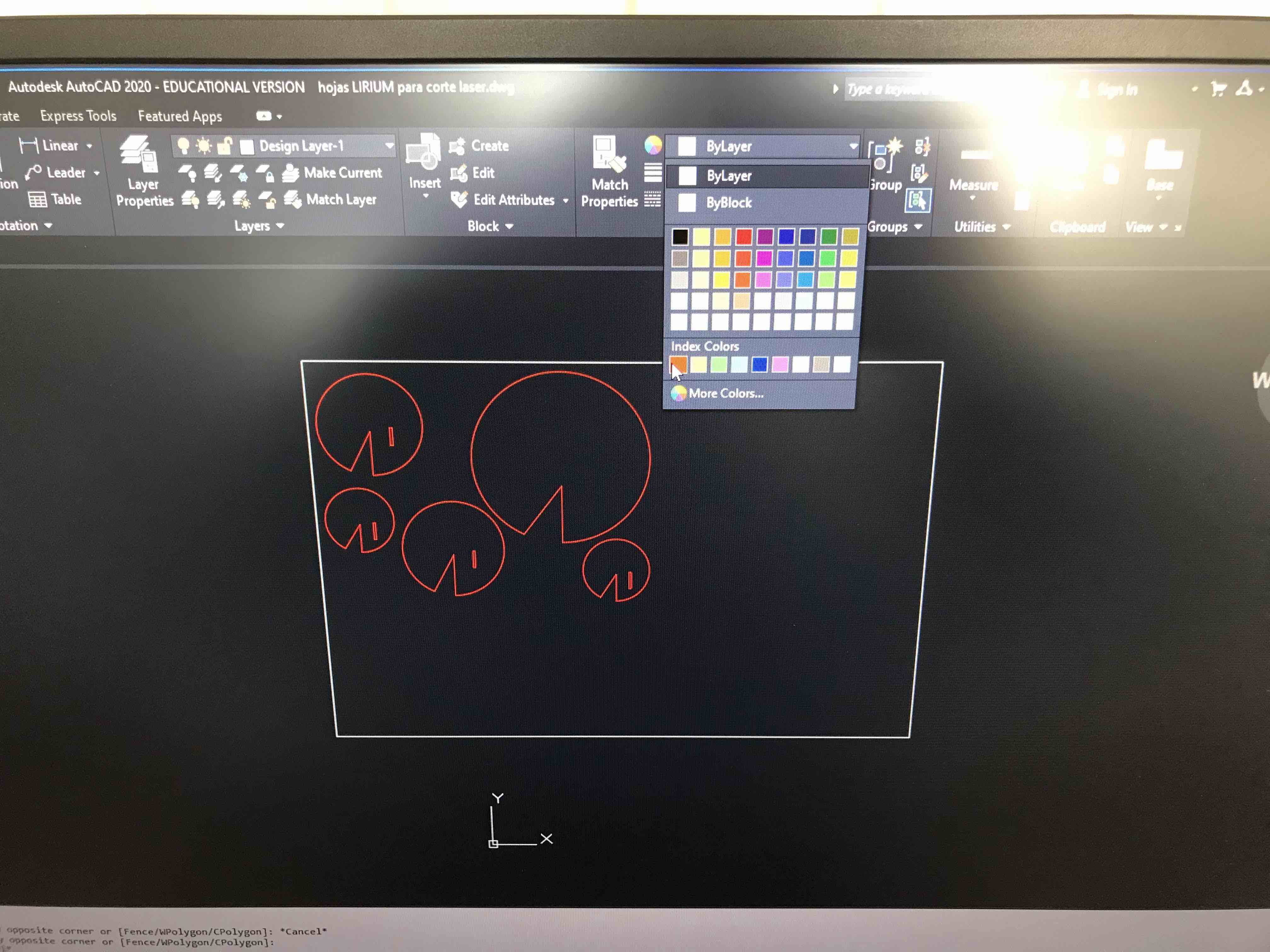
The leafs covers in
Autocad, this drawing is in a DWG format. Here I´m choosing the
color of the layer so the laser machine knows if it is a cut or
just engrave.
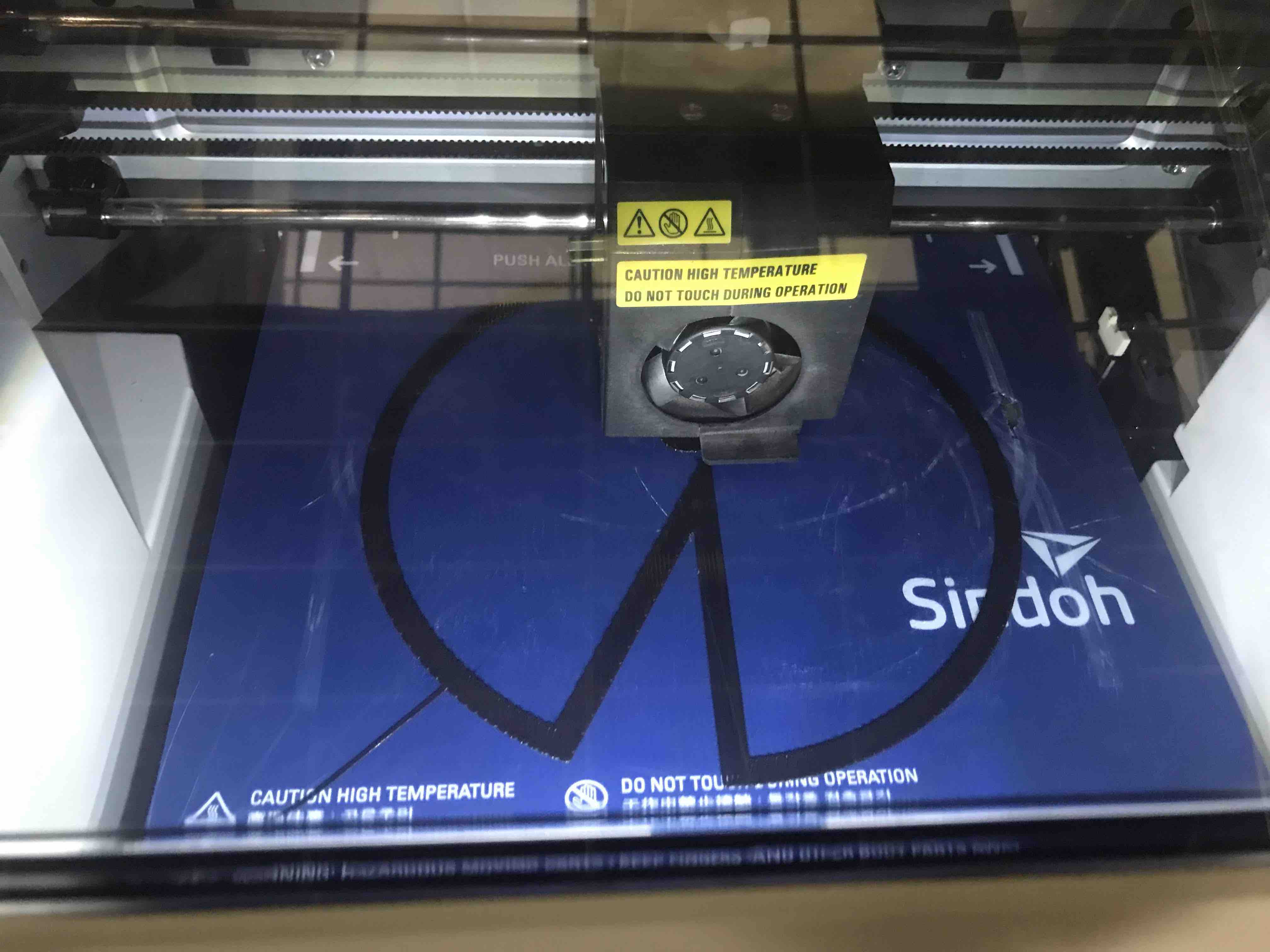
Here you can see
that is printing the support that atache the object to the bed
of the machine, over this will start to print your final piece
electronics
a place to re-connect
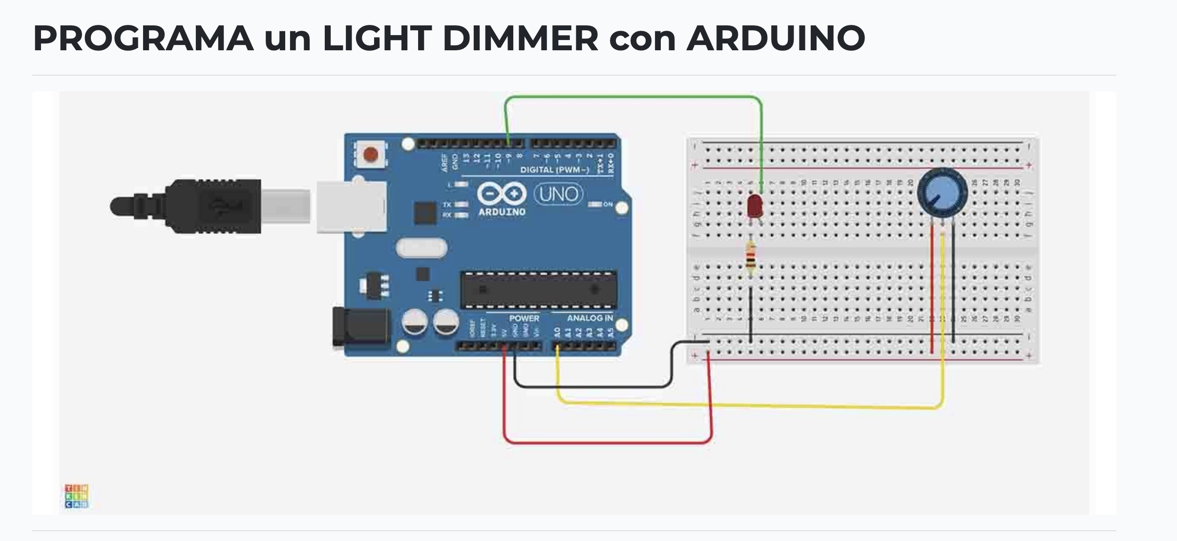
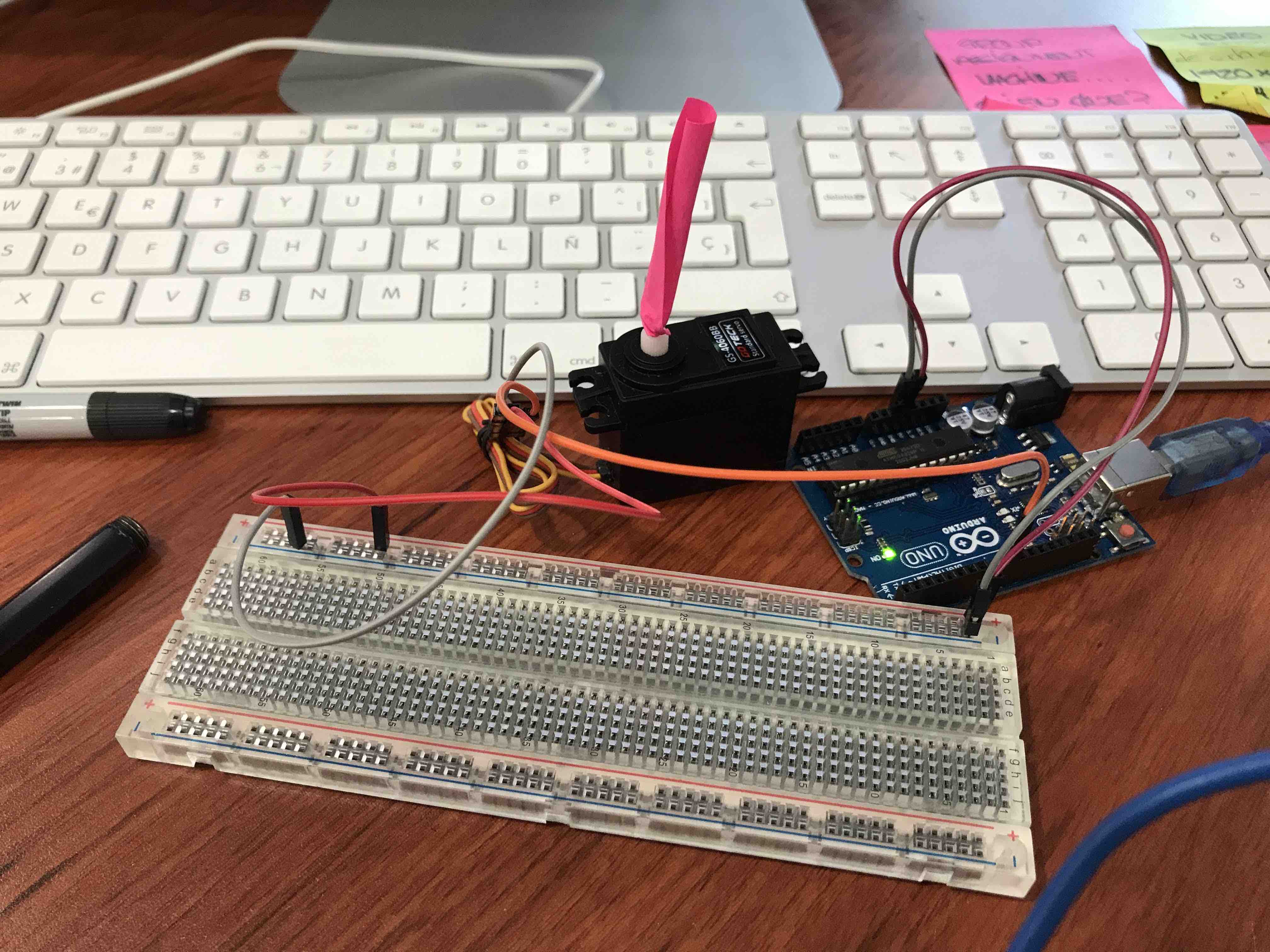
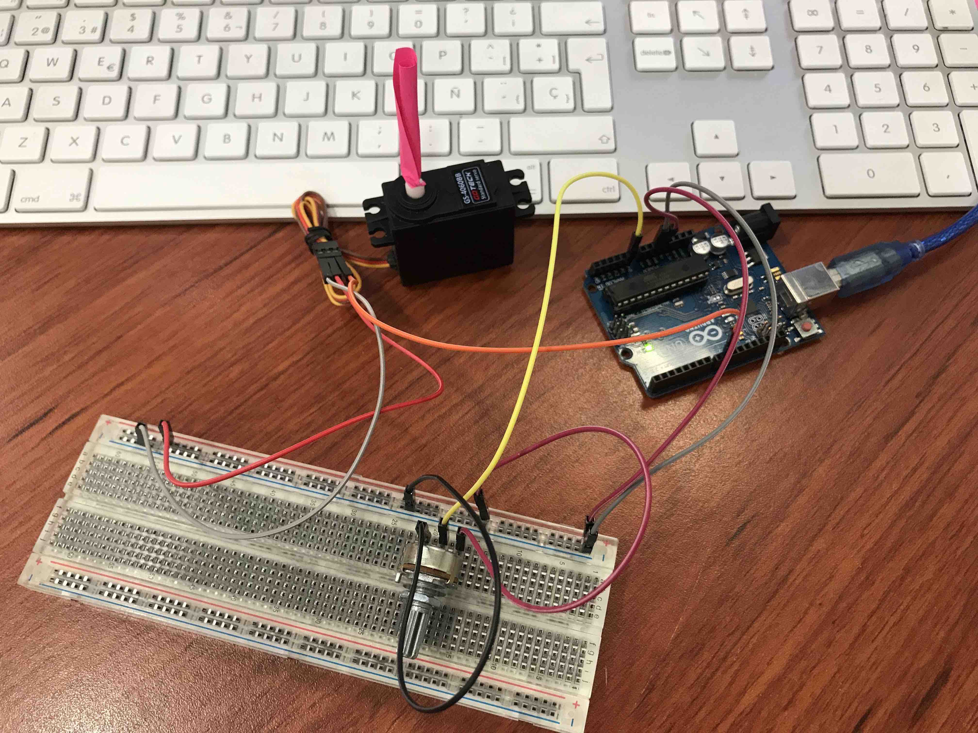
first Ilook for the
schematics of Arduino for the Servo and the LEDS with LDR to start
to do some programming and test the variables of the code
first Ilook for the schematics of Arduino for the Servo and the LEDS with LDR to start to do some programming and test the variables of the code
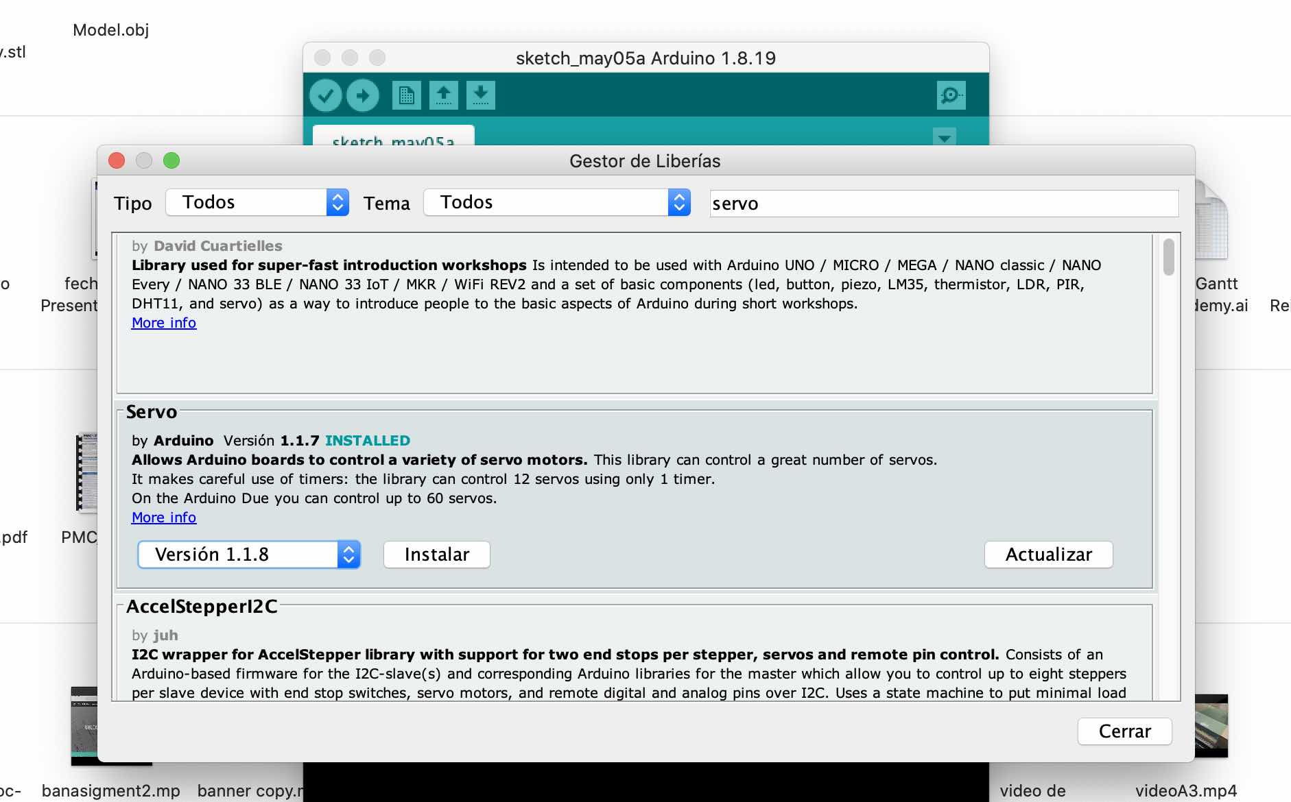
Then I look and
install the libraries missing for the servo
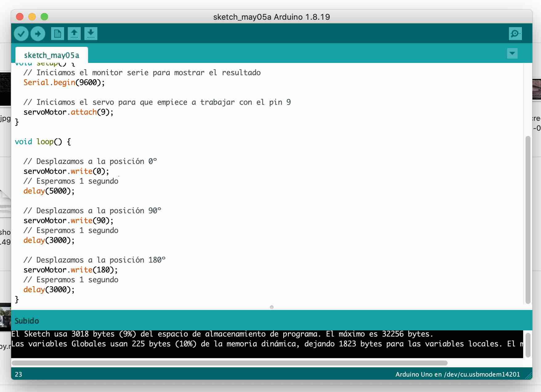
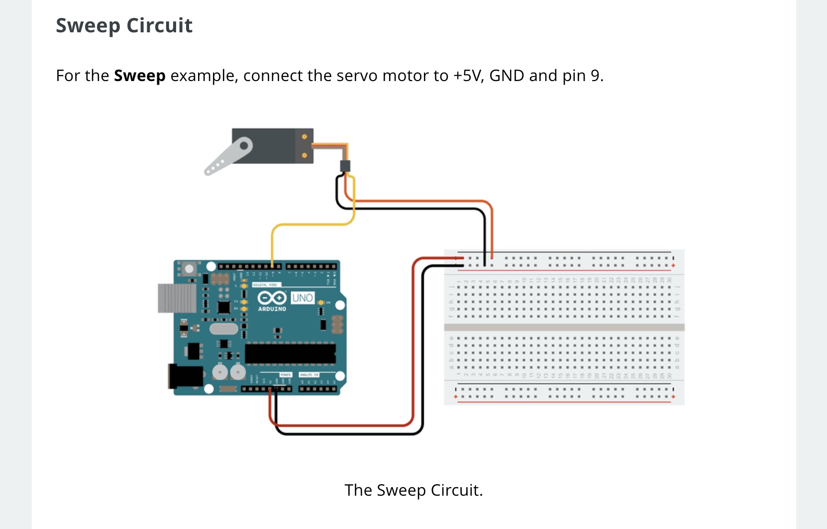
Here´s a code that
moves a Servo motor in different degrees, thats just what I need
for my project.
And works well, it
was easy
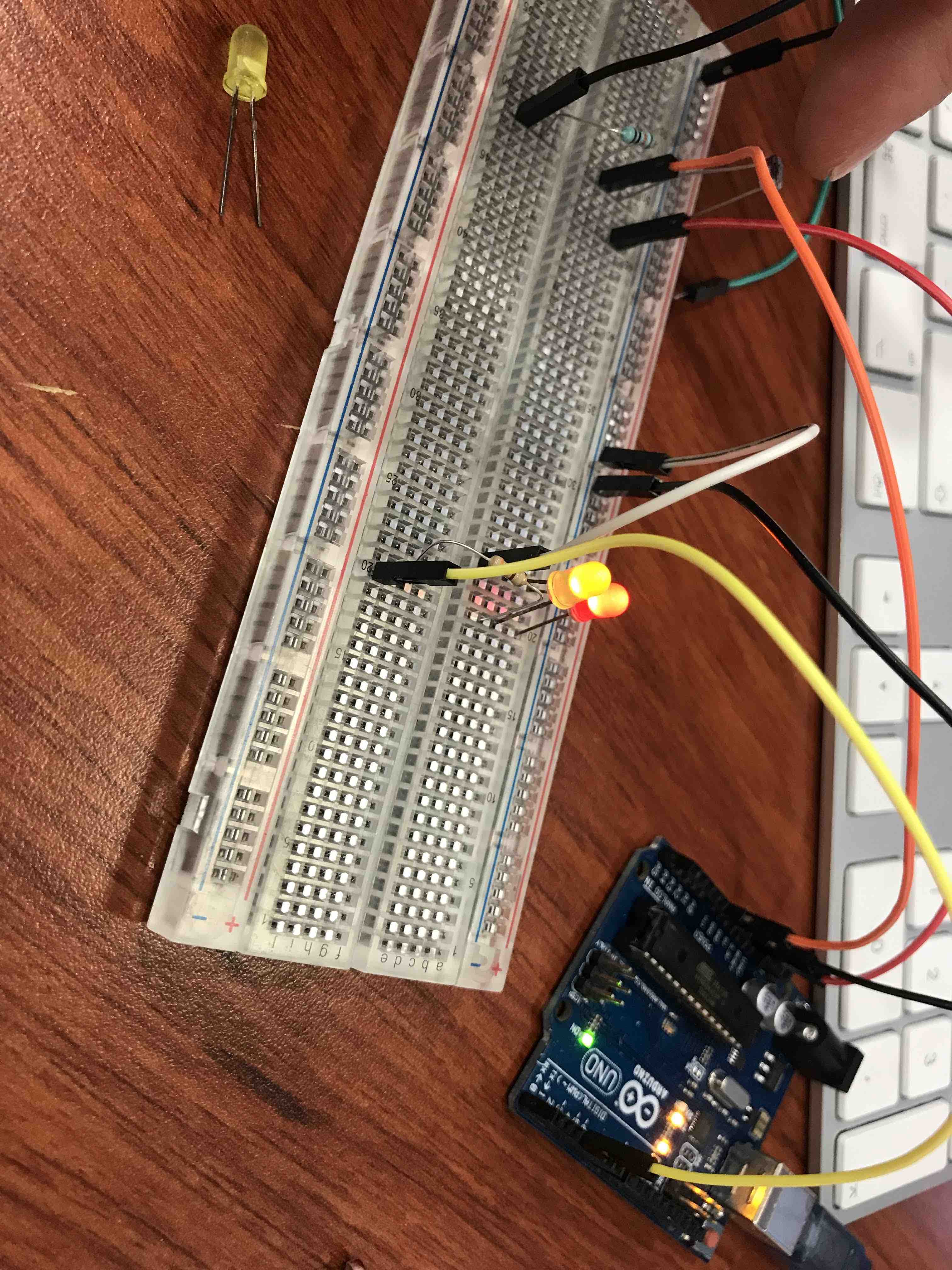
Here I´m testing leds
ON/OFF with an LDR

Then I redesign the
SAMDINO to fit my requeriments so I can replace the arduino with
it and start programming a new code
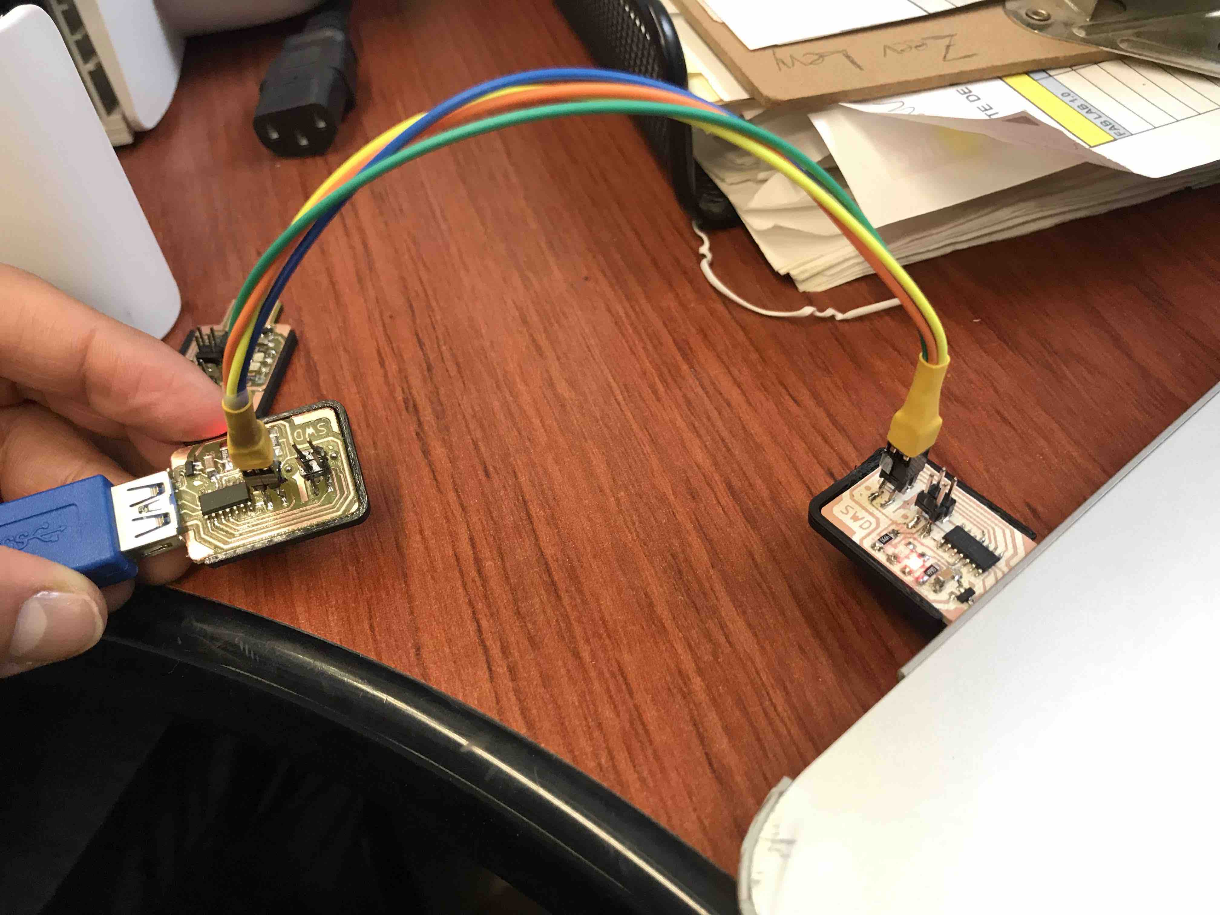
First I had to
connect my SWD to "life" so I can program my PCB Hugodino with
this
Here are the hugodino
board and the SWD, the connection was ok
Everything goes well.
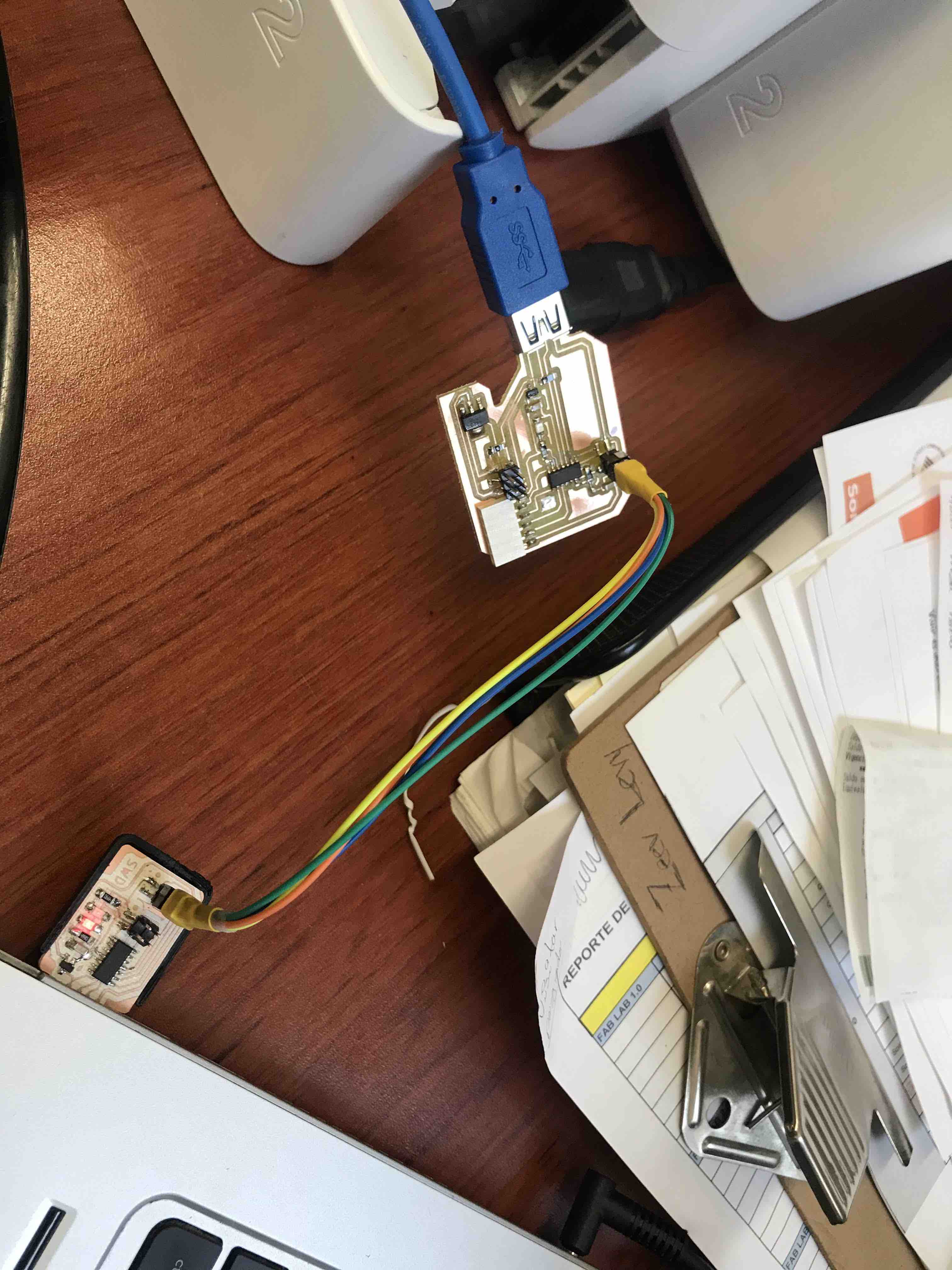
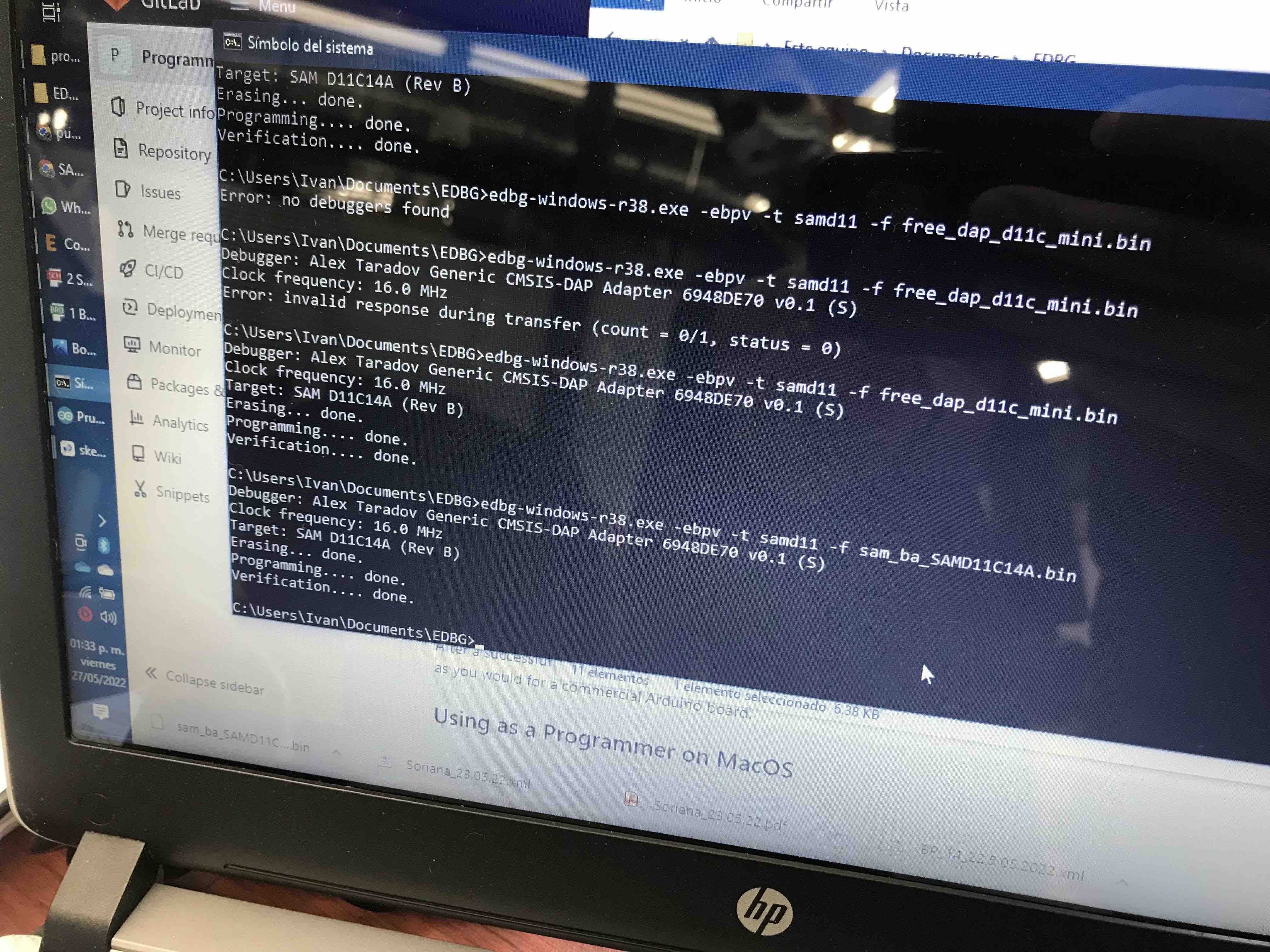
Here we use the EDBG to "turn on" the hugodino board using the WSD
PCB
The led of my PCB is
on indicating we are good
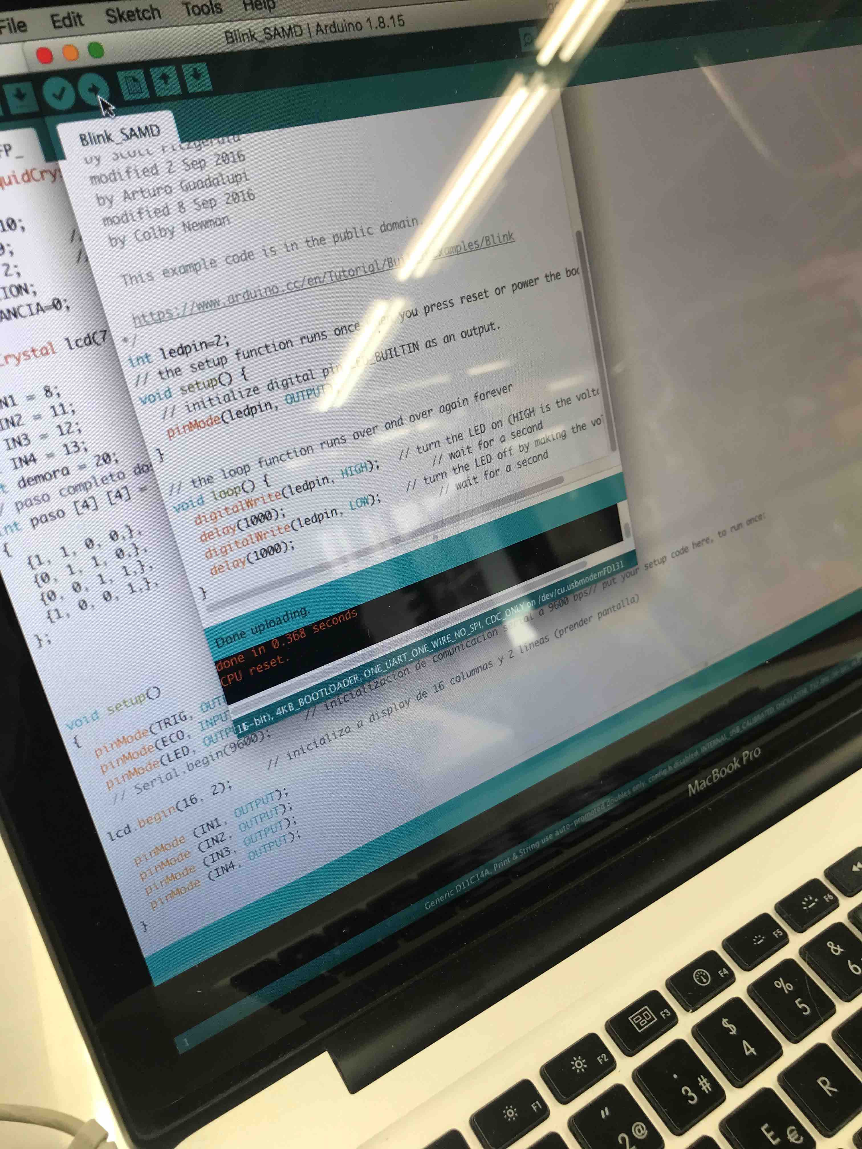
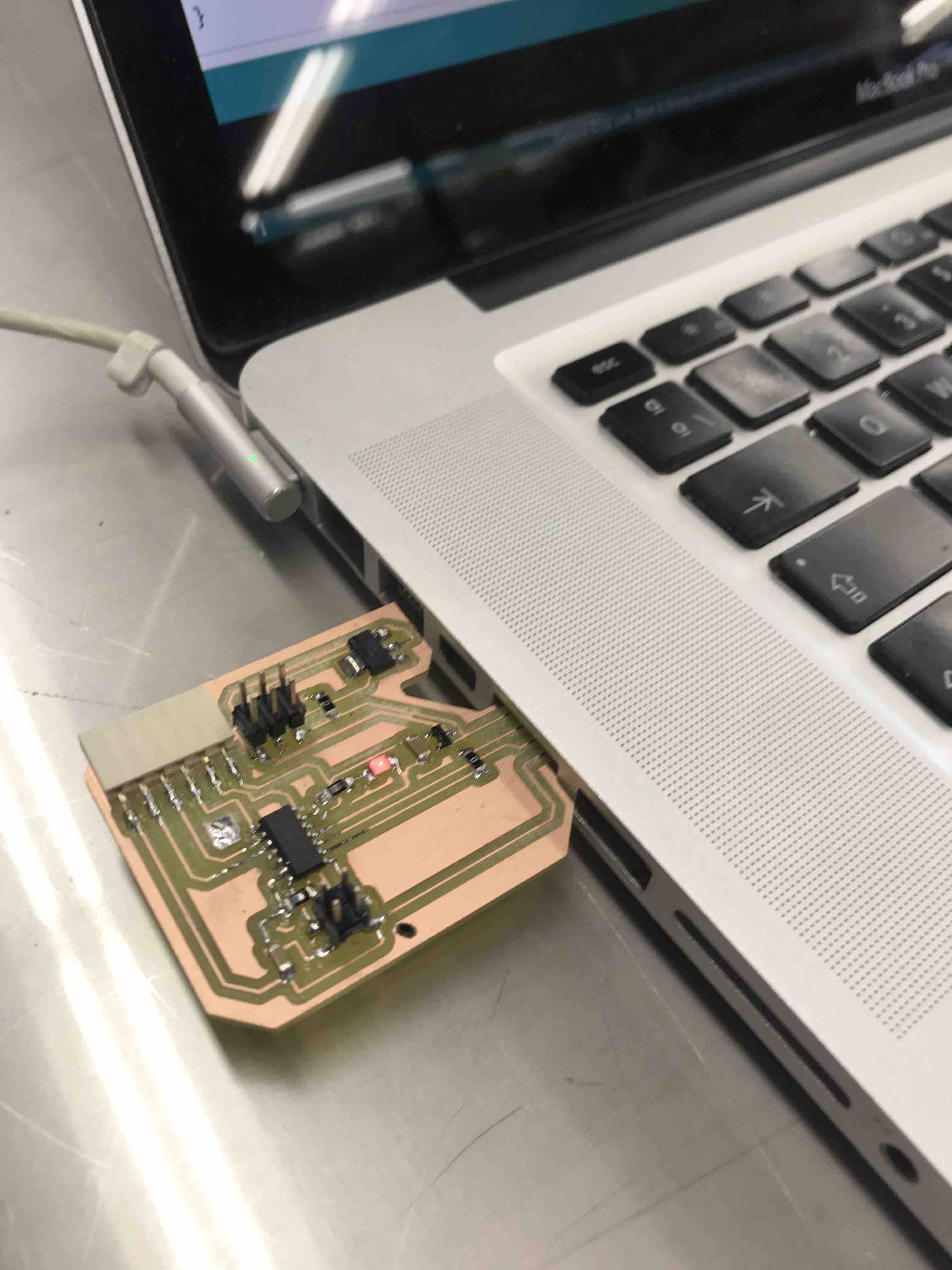
Mhere the code for
the SAMDINO that makes the LED blink, in the future I´m going to
use the SAMDINO code to design my own codes to fit my requirements
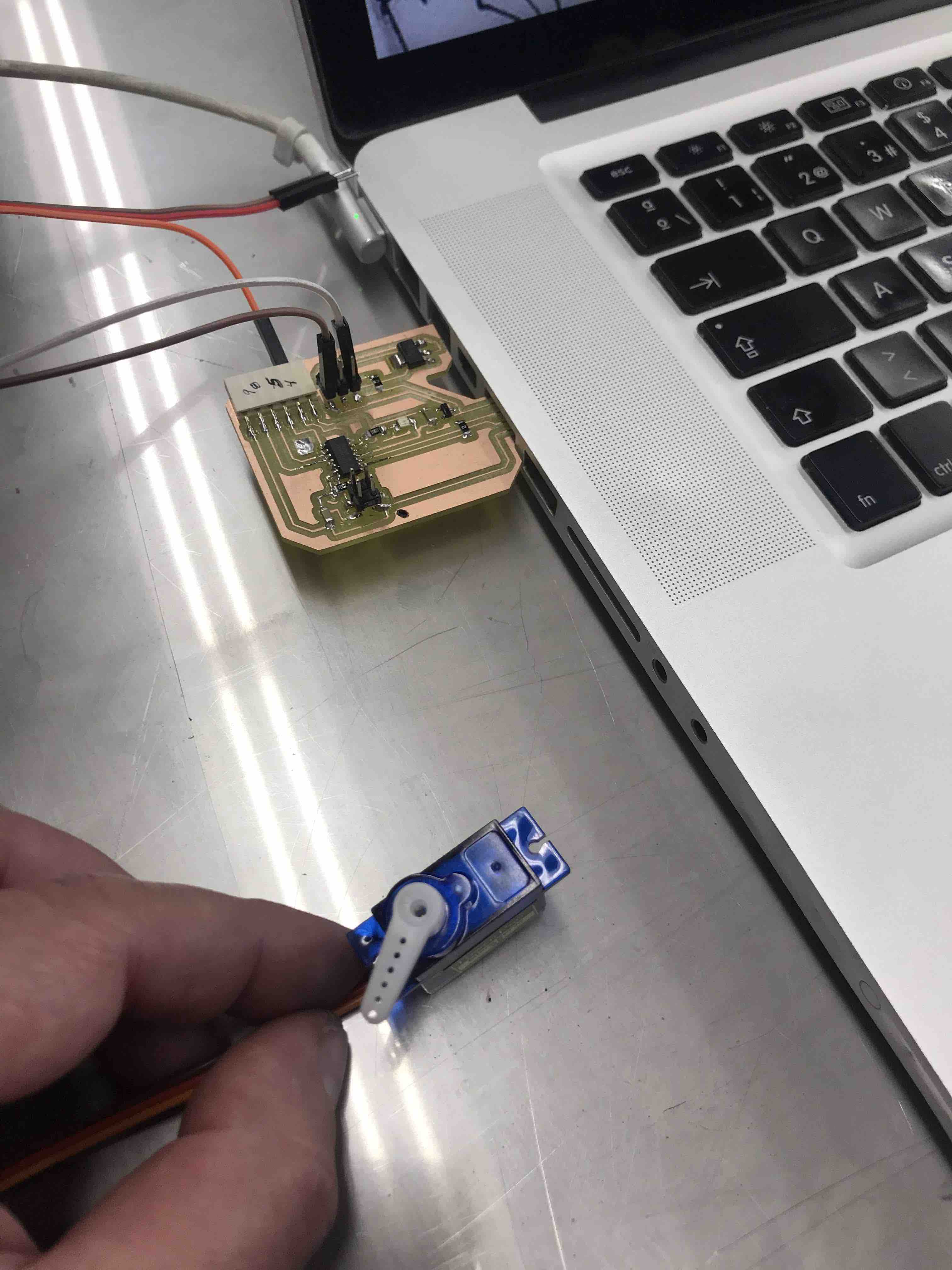
The servo is moving,
thats really fine
prototype
a place to re-connect