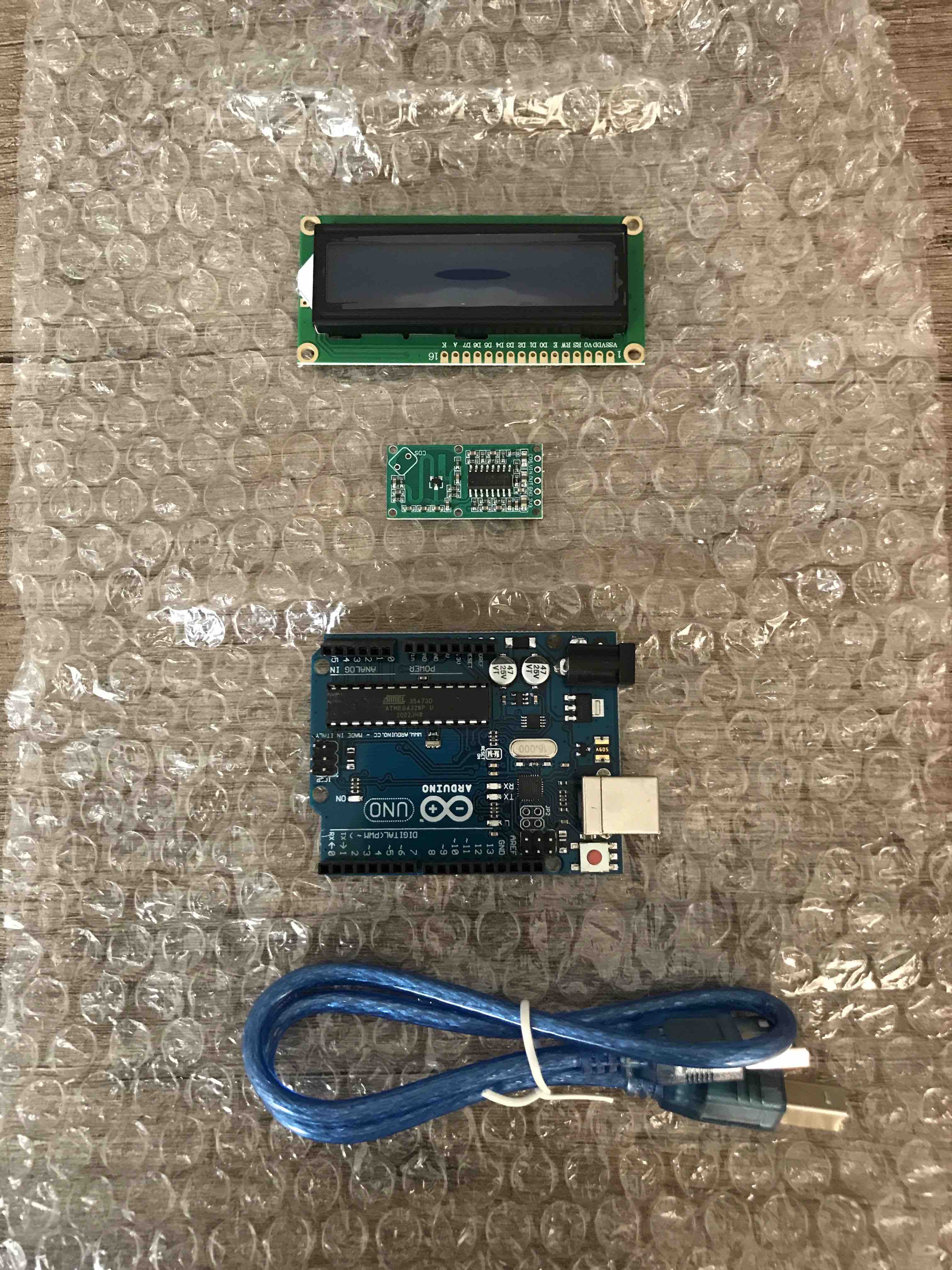
Arduino Uno,
LCD display, breadboard, Dupont cables, Code, Eagle, copper
plate (for the PCB), Modela machine, Welding, microcomponents,
SAMD11
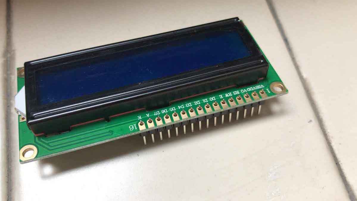
First I weld the set
of jumpers to the LCD display
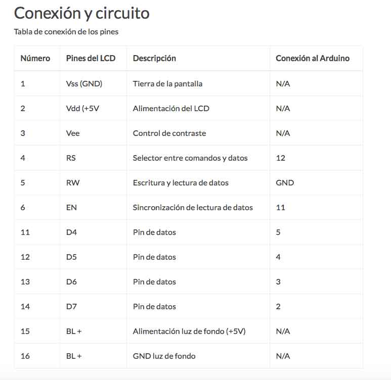
Number, Pin,
Decription and connection to Arduino
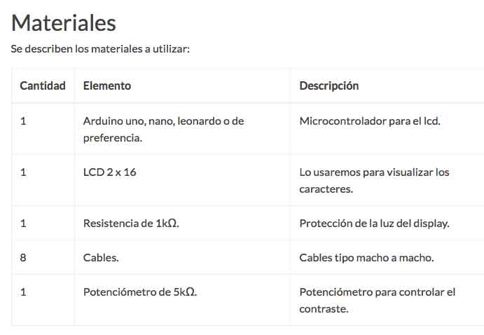
List of materials
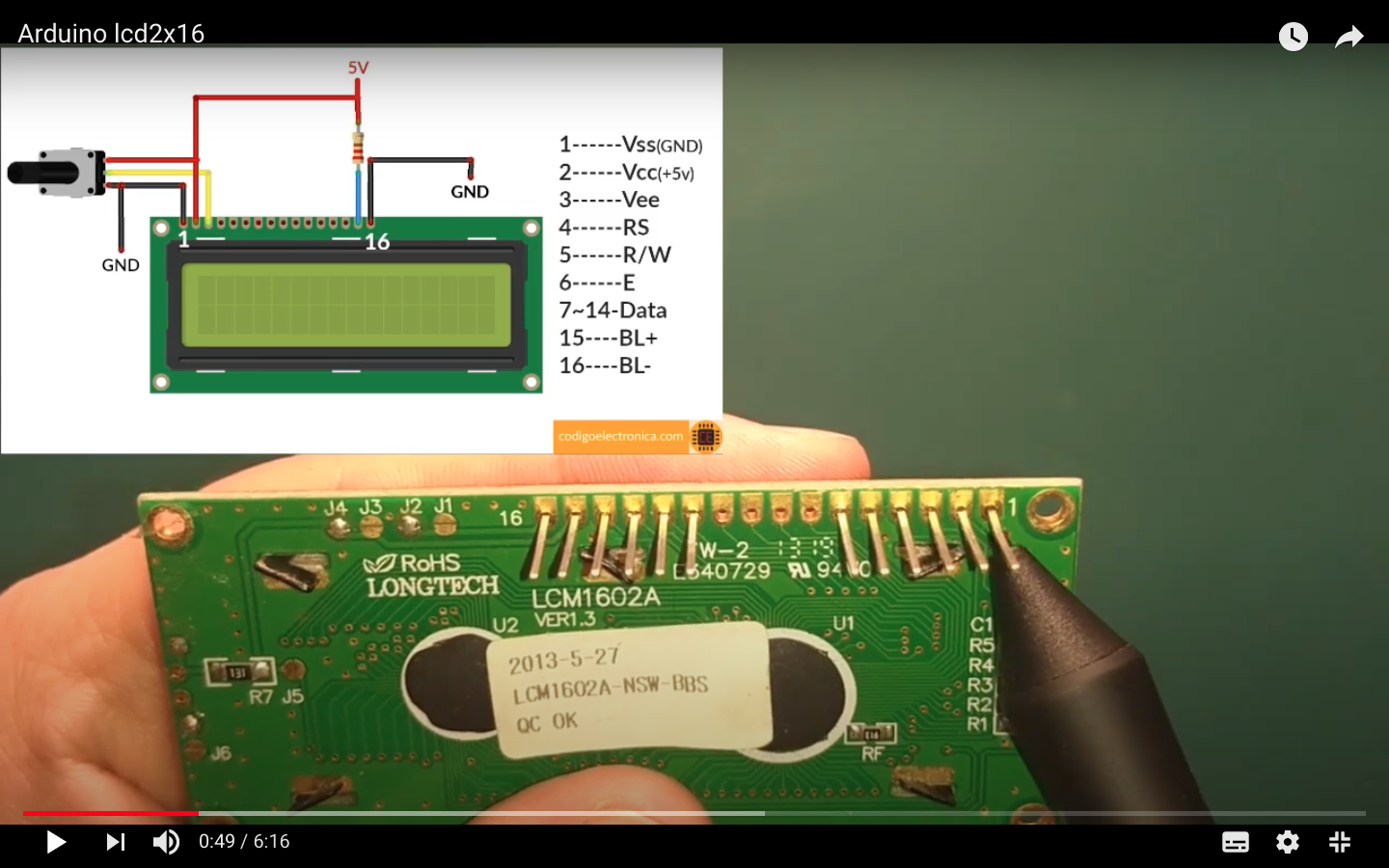

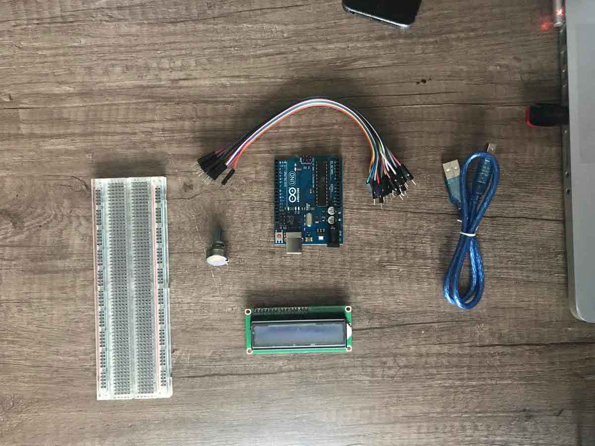
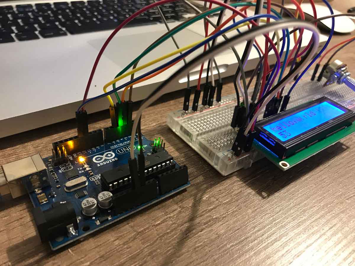
Connections between
the arduino and the breadboard to connect the LCD disply and the
potentiometer

First connections:
ground and VCC
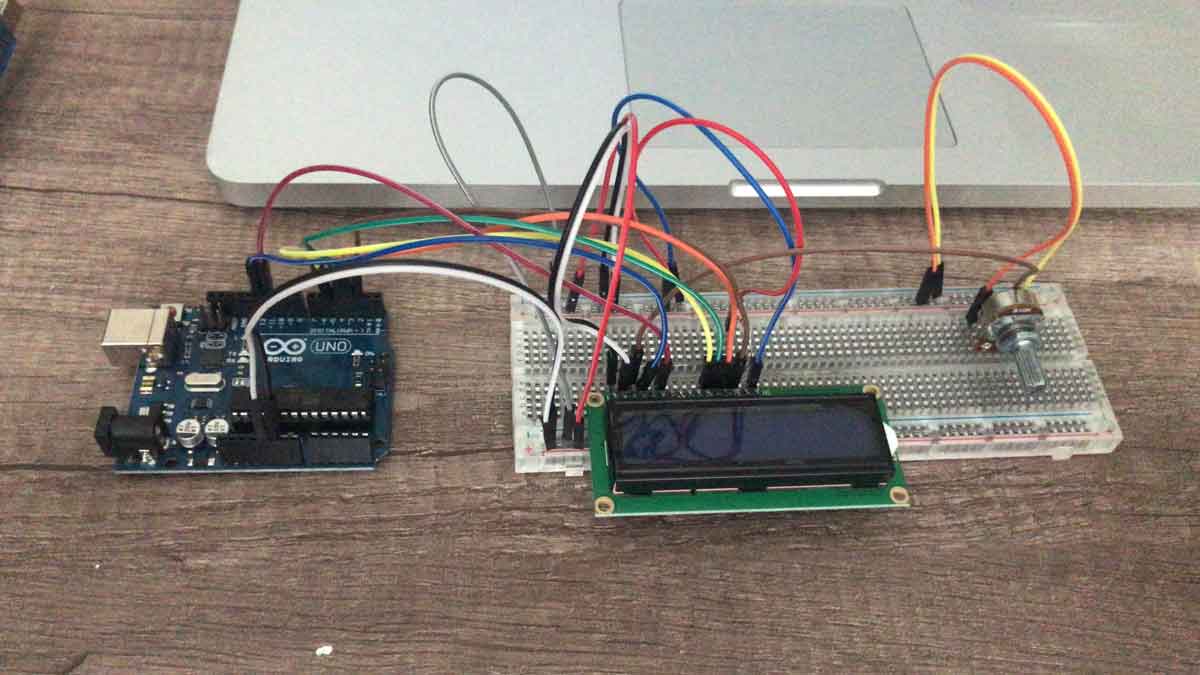
All the other
connections following the schematic above
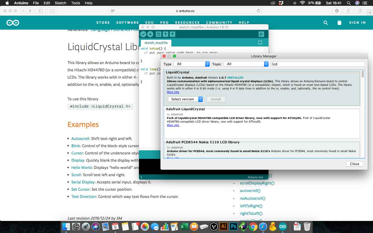
Then I need to add
some libraries to the Arduino
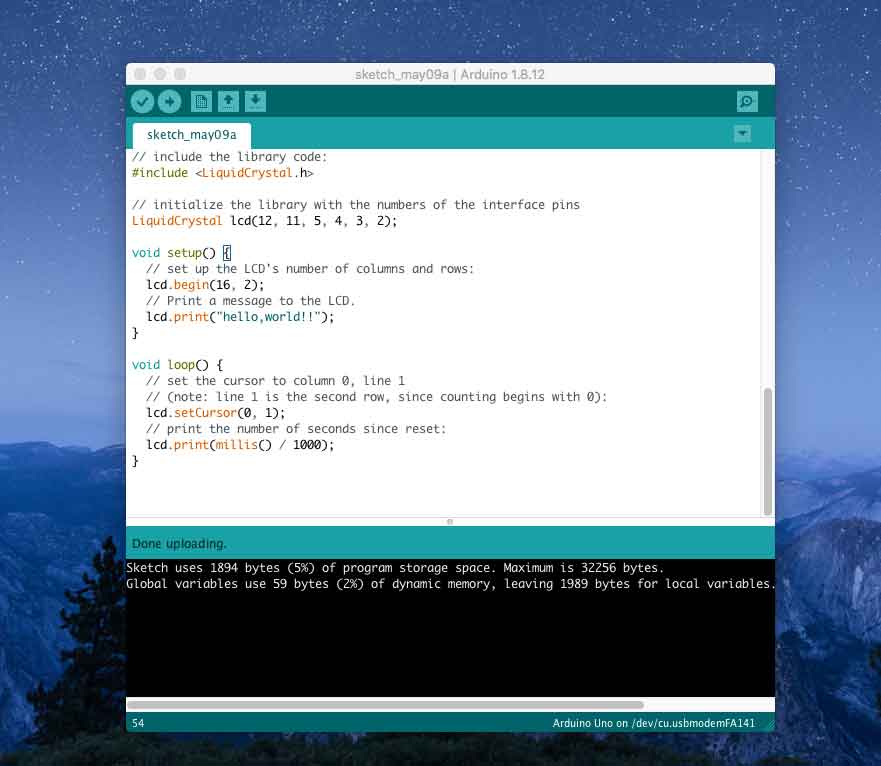
And this is the
original code i use to tst the LCD display, later i change some
lines to adapt it to my future project.
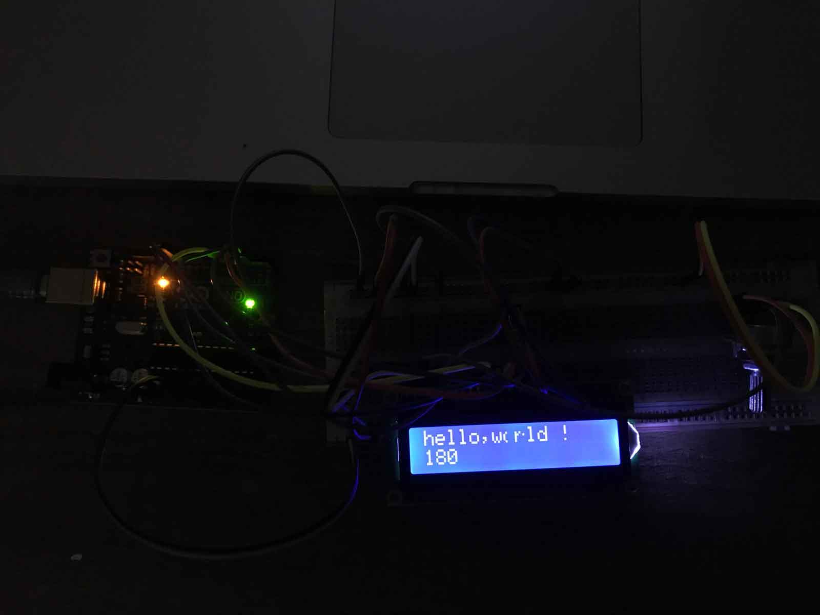
Every seems fine, the
code works properly and the LCD shows the text, with the
potentiometer you can adjust the contrast of the display
almost 2 years later, when we return to the lab.....
and the link to the group assignment is: FabLabCDMX.
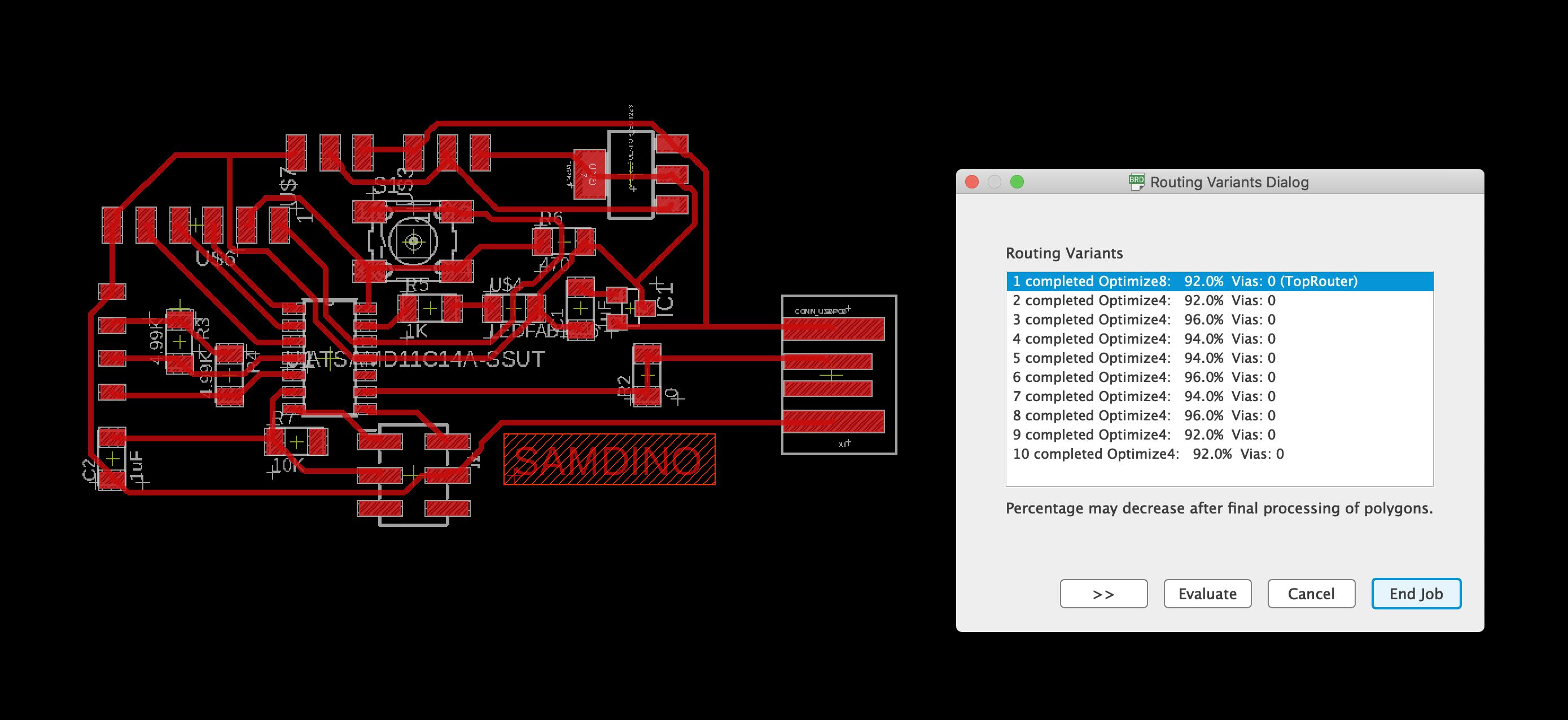
The original
SAMDINO, I use this design as the initial design, then I
change some components and made a new schematic in order to
fit my Final Project rqueriments
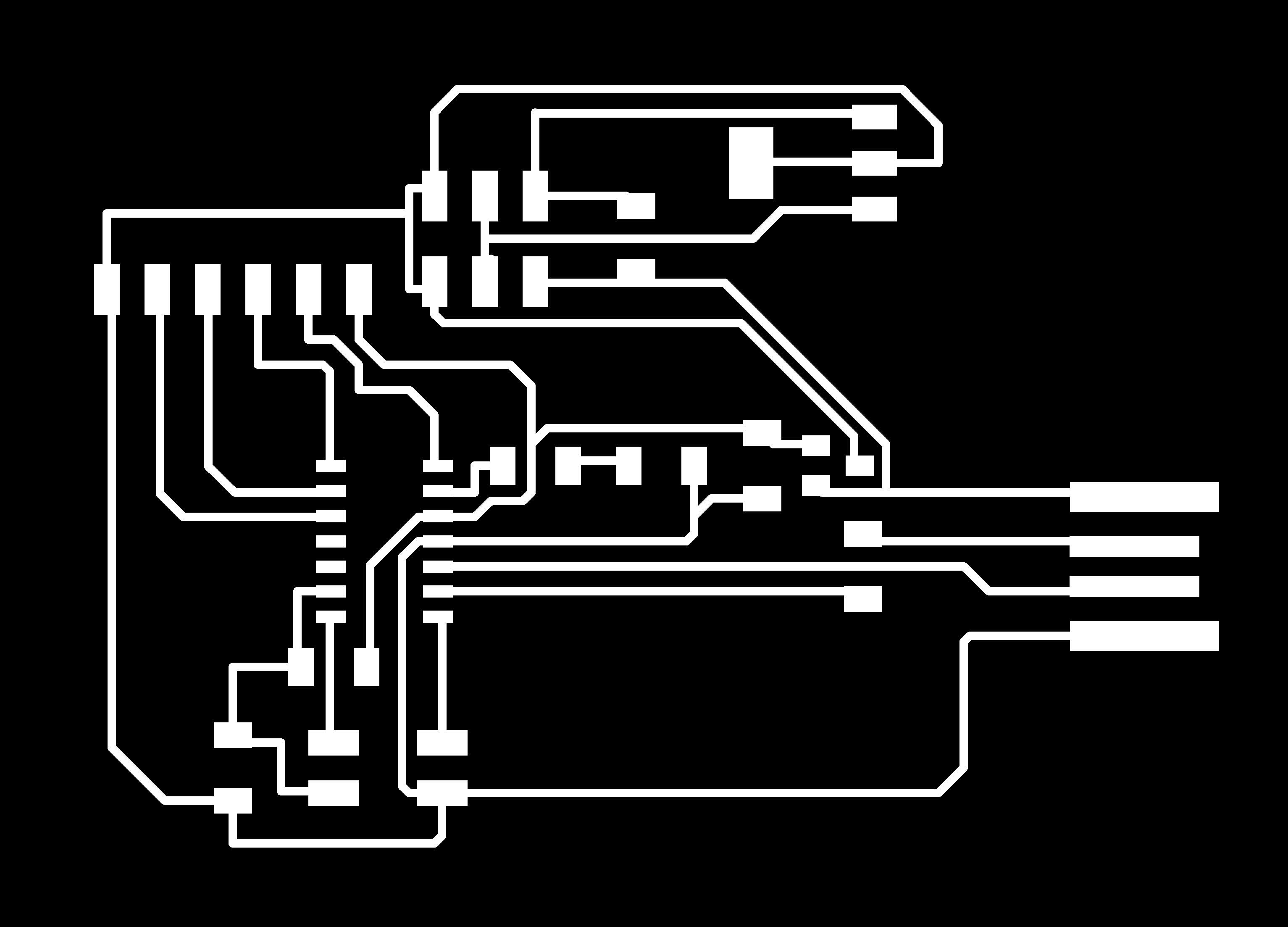
A PNG image of
my PCB, we need to export the image in this format to open
it in MODS
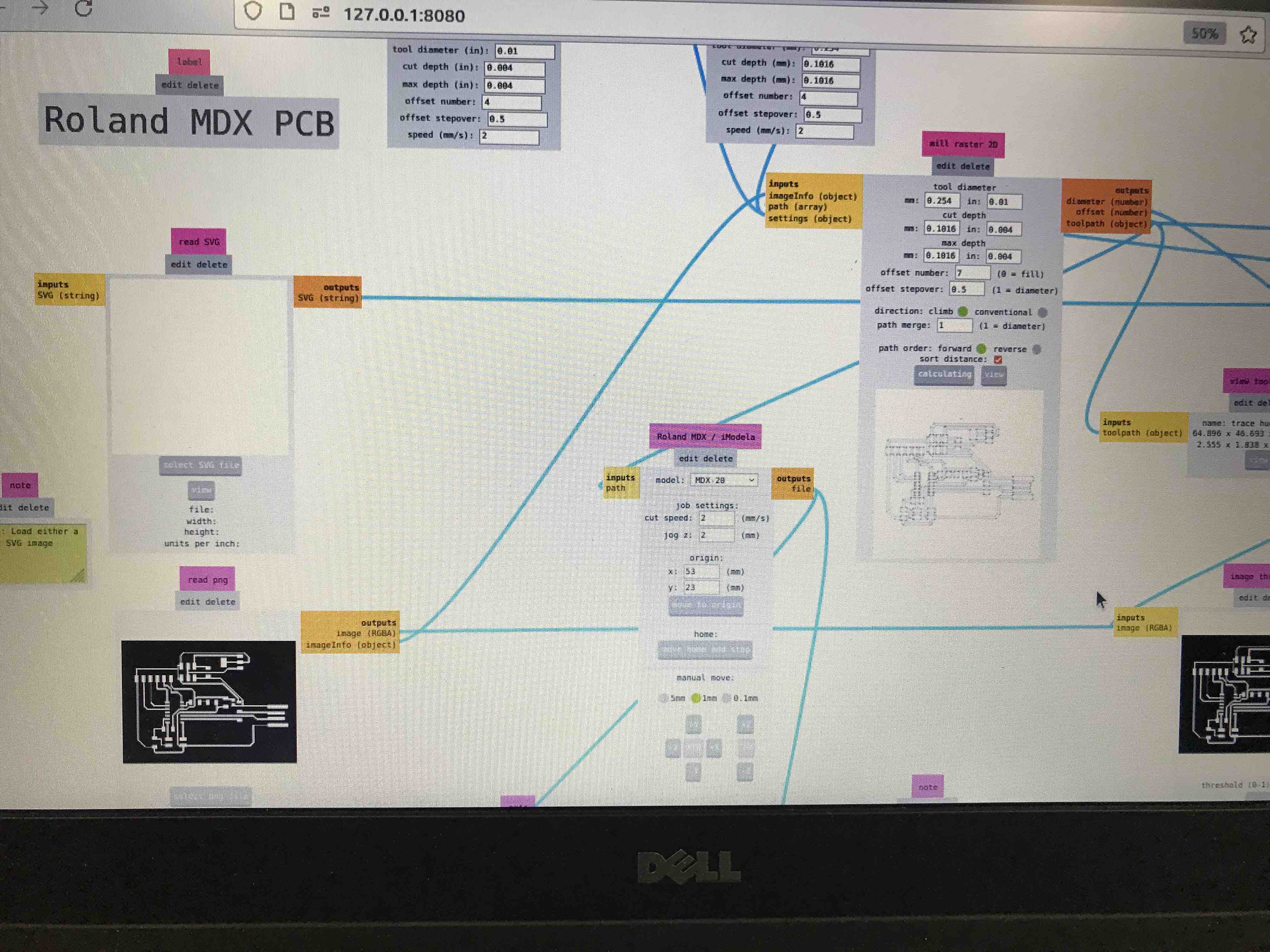
I use MODS to
set up the Modela for milling my PCB
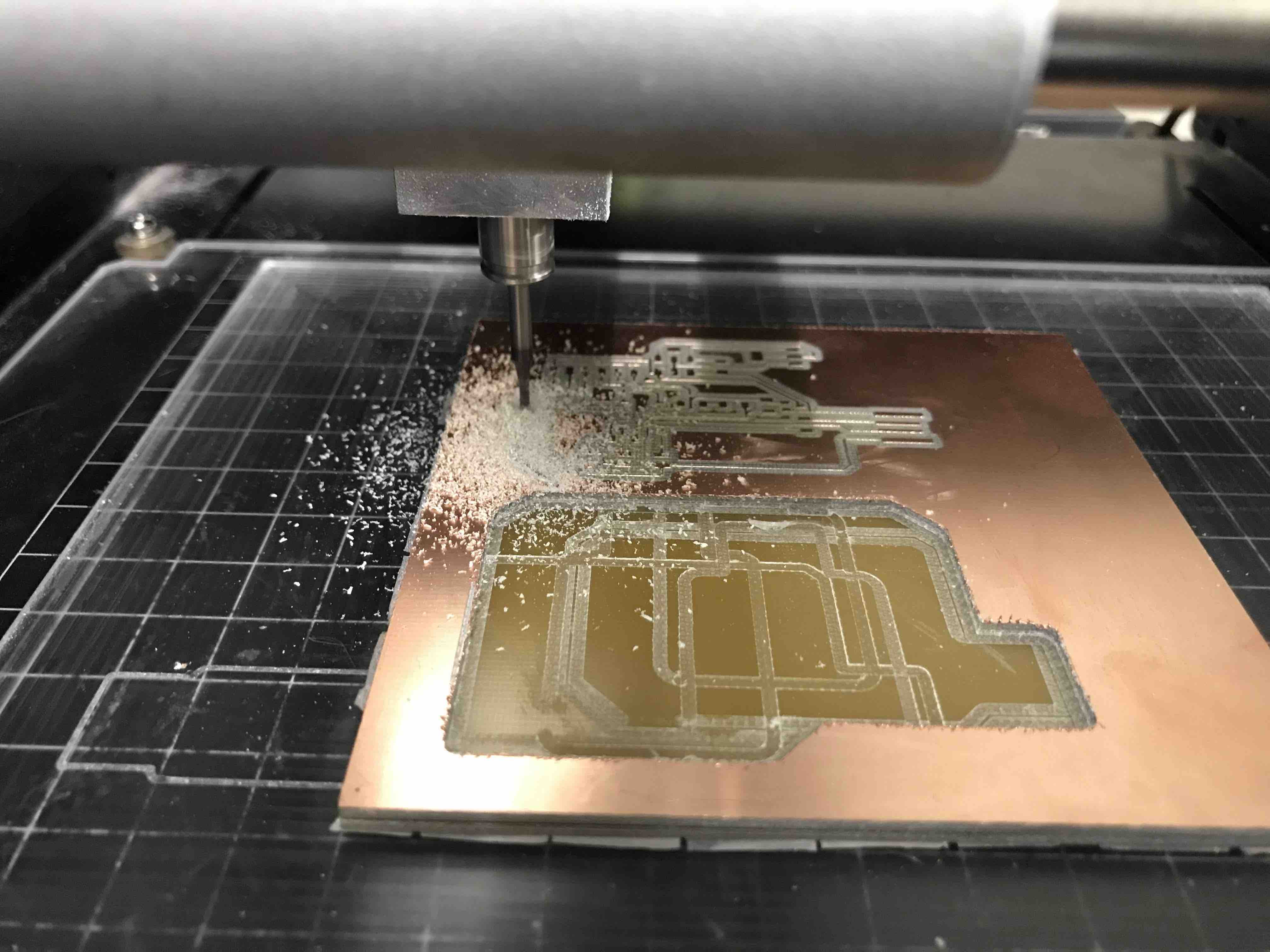
The Modela
machining my PCB in the copper plate
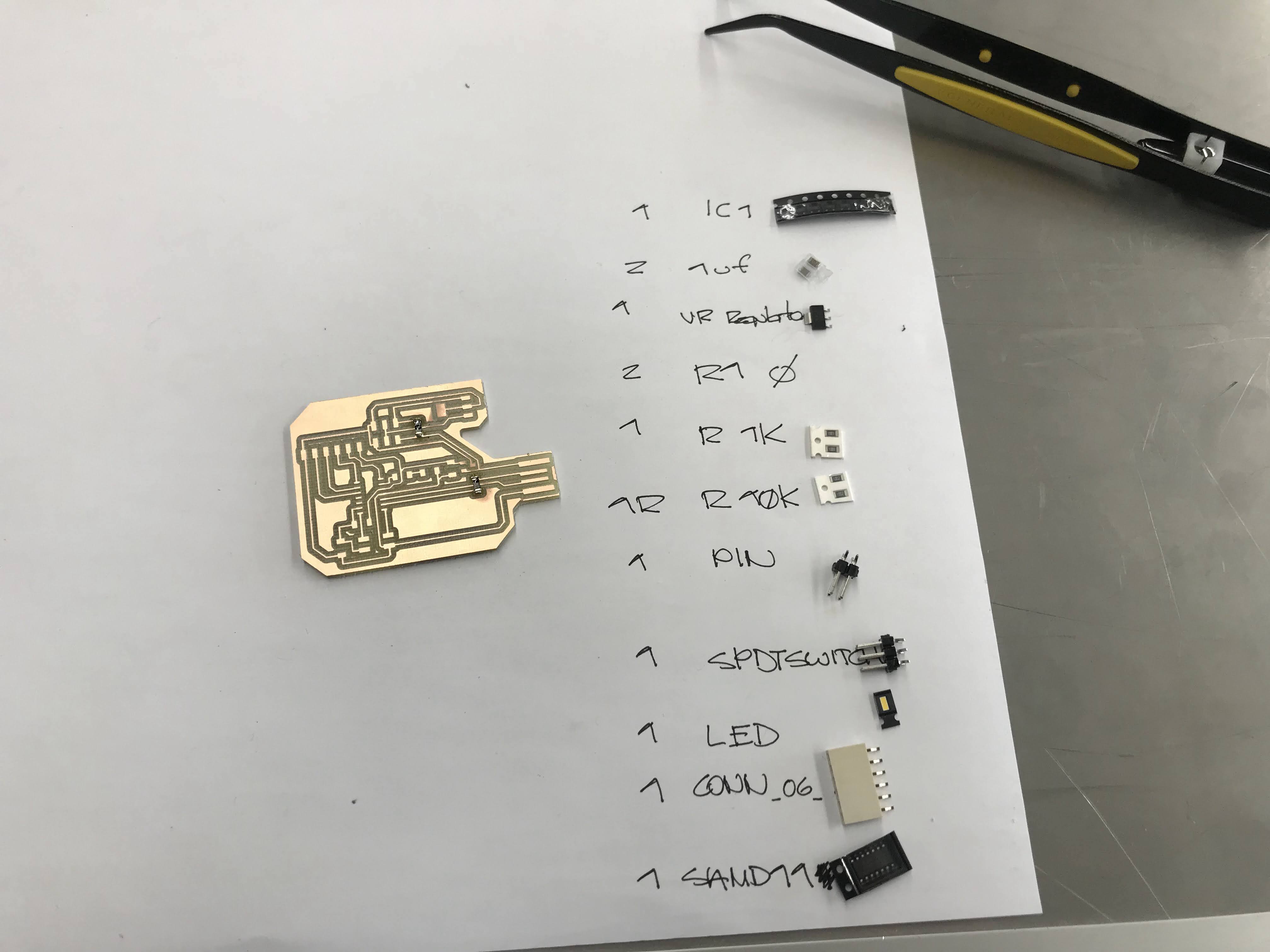
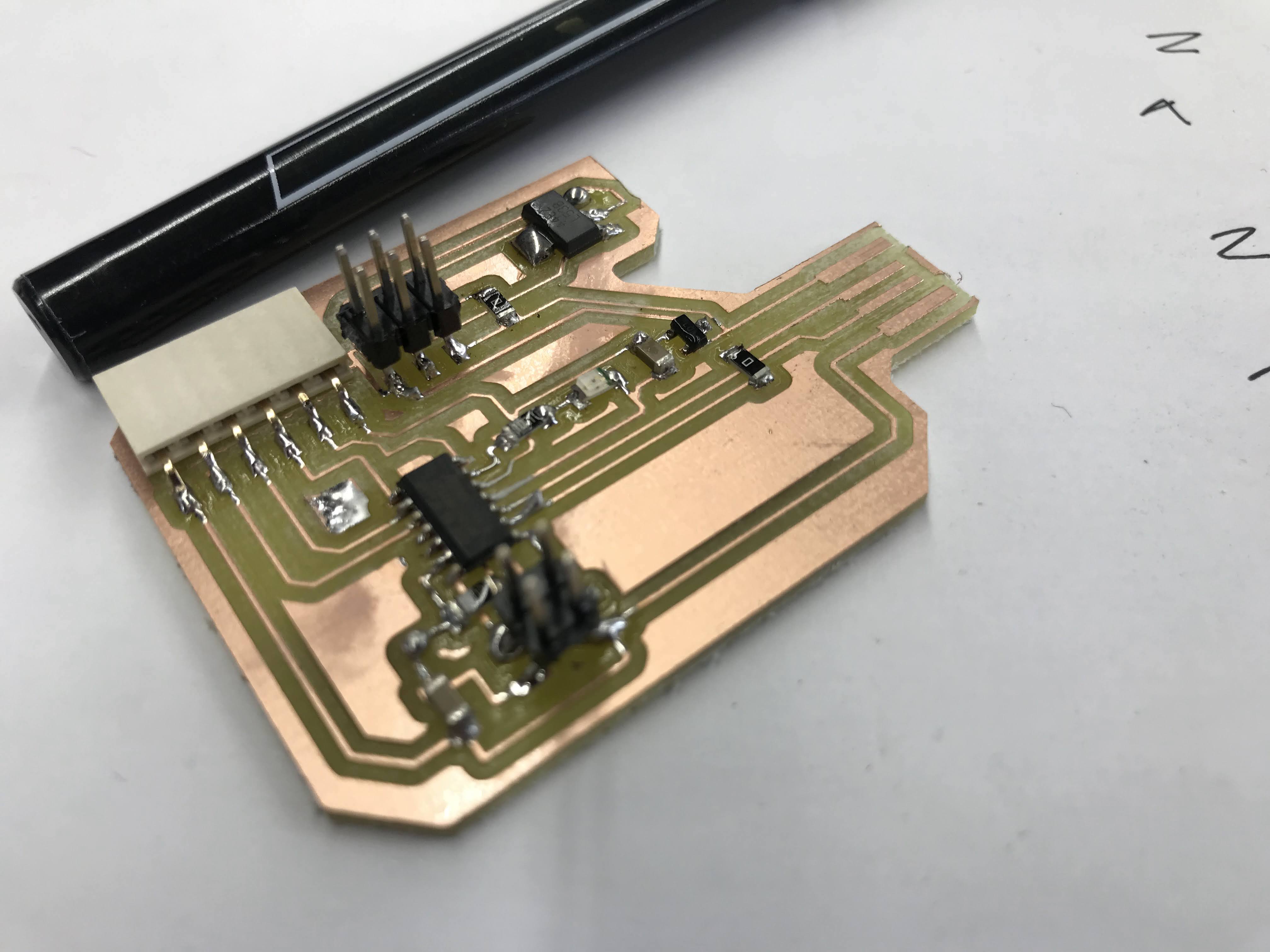
My PCB and the
components I need to weld it
For this
assignment I want to blink the PCB led to check comms, then
the servo rotate and the led will go ON and OFF (HIGH and
LOW)
the servo only
rotates from 0 to 180º VS a step motor that rotates 360º but
for assignment purposes I will use the servo, so, in this
tst code first the red led will turn ON and OFF, then the
servo moves into 3 different positions and then the wearable
LED (lamp) will turn ON, OFF and ON again
Here is the
code and a video
int
led = 2;
int servo = 8;
int angle;
int pwm;
int lamp = 5;
void setup()
{
pinMode(servo, OUTPUT);
pinMode(led, OUTPUT);
pinMode(lamp, OUTPUT);
}
void loop ()
{
//Probe PCB board function
digitalWrite(led,HIGH);
delay(1000);
digitalWrite(led, LOW);
delay(1000);
//Move servomotor
servoPulse(servo, 15);
delay(1000);
servoPulse(servo, 120);
delay(2000);
servoPulse(servo, 180);
delay(4000);
//turn On & turn off lamp
digitalWrite(lamp, HIGH);
delay(500);
digitalWrite(lamp, LOW);
delay(1500);
digitalWrite(lamp, HIGH);
delay(500);
}
void servoPulse (int servo, int angle)
{
pwm = (angle*11) + 500; // Convert angle to microseconds
digitalWrite(servo, HIGH);
delayMicroseconds(pwm);
digitalWrite(servo, LOW);
delay(50); // Refresh cycle of servo
}
PRODUCT DISPLAY
for our students
projects