
Building the site is the primary goal. Thank to Lorenzo, I made an online course with CodeCademy and in a few days I knew the html/css principles which I found very easy and amusing.The structure is composed by Three pages: the first one is the home page where you get the basic informations and the link to the other two pages.
The second page is about me, what I did and what I do now. The third (this one) will have all the work, the documentations and the exercises.
Divide the page the way I want was a bit tricky ... Margins, Borders, Paddings, Contents and their relative properties when they interact with other elements, is at the very beginning difficult,until you remember all the command. The code was written in a text-editor program called "Sublime Text", It has some usefull things like line index, color code highlights. And "firebug" is an helpful extension to my browser. I like a "minimalistic style" site ... well mine is not the case :-), I choosed to test and play with various commands and tricks as part of the exercise.
In the Home Page, The list of the Assignments change color when mouse is pointed on ... Green for the Assignment done, and Red for the Assignment to do.
        .text:hover {
            color:red;
            transition:0.5s;
            transform: scale(1.1,1.1);
            -webkit-transform: scale(1.1,1.1);
            -o-transform: scale(1.1,1.1);
            -moz-transform: scale(1.1,1.1);
           -moz-transition:0.5s;
        }
       .text2:hover {
           color:#19A319;
           transition:0.5s;
           transform: scale(1.1,1.1);
           -webkit-transform: scale(1.1,1.1);
           -o-transform: scale(1.1,1.1);
           -moz-transform: scale(1.1,1.1);
           -moz-transition:0.5s;
        }
The Picture of the Boat change the size as mouse in pointed on ...
                    .hcenter:hover {
                    margin: center;
                    opacity:1;
                    text-align: center;
                    transition:1s;
                    transform: scale(1.1,1.1);
                    -webkit-transform: scale(1.1,1.1);
                    -o-transform: scale(1.1,1.1);
                    -moz-transform: scale(1.1,1.1);
                    -moz-transition:1s;
                    }
Another interessing thing is the possibility to have link not just to a page but directly to a choosed point of the page: the first line is the link to the page named "theassignment" and "#cad" point directly where the id="cad" is positioned
//in the page: "index.html"
<a class="text2" href="theassignments.html#cad"> computer-Aided design </a>

//in the page "theassignment"
<h2 id="cad">Computer-Aided Design</h2>
//This Part is located in the Header (omitted the code out of topic)

<head>
omitted

<style>
#galleriaprojman{height:640px; width: 100%; display: block; margin: 2em 0;}
</style>

</!-- load jQuery -->
</script src="http://ajax.googleapis.com/ajax/libs/jquery/1/jquery.js">/script>
</!-- load Galleria -->
</script src="galleria-1.4.2.min.js">/script>
</!-- load picasa plugin -->
</script src="galleria.picasa.min.js">/script>

</head>


//This is the part where the pictures are inserteded in the page

<div id="galleriaprojman">
    <img src="photos9/milling01.jpg" data-title="Test Test Test" data-description="Picture Description">
    <img src="photos9/milling01.jpg" data-title="Test2 Test2" data-description="Picture2 Description">
</div>


// Load the classic theme (this part is inserted at the bottom of the page)
Galleria.loadTheme('themes/classic/galleria.classic.js');

Galleria.run('#galleriaprojman',
    // The user & album on Picasa.(omitted in my case because we wanted the image on the MIT server)
    //picasa:'useralbum:104195930708789857863/ProjectManagement',

});
19-May Updates
A new page for the final project was created, I wanted to have a dinamic menu but I'm still in working progress on the programming side ... so instead of using .js, I found a way the the knowledge I already have ... few line of CSS:
    .sposta02 {

    position: absolute;

    left: -340px;

    top: 104px;

    height: 430px;

    width: 370px;

    background-color: #101010;

    opacity: 1;

    border-radius: 2px;

    margin: 0px;

    color: red;

    line-height: 1.2em;

    z-index: 999;

    text-decoration: none;

    }


    .sposta02:hover {

    transition: 1s;

    transform: translate(340px,0px);

    text-decoration: none;

    }
A special thanks to the "Web Master Guru" Alessandro Papaleo who always helped with hints and most of all ... his debugging help when my page was doing some crazy things or didn't obey to my coding :-) ... I also discovered with his help a very helpful feature of my text editor (Sublime Text): you can copy cut and parts of the code just by dragging it to the desired place.
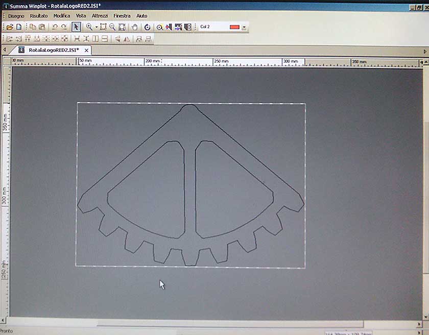
We started this assignment with the programs used in the graphic field: Gimp and Inkscape. The latter was a very nice surprise, I used Adobe Illustrator time to time, his interfase is quiet familiar to me, I have a 25 years professional experience on using Photoshop ... Lorenzo gave me some hints to start and after a few hours I had no problem to navigate the menus and using it the same level I used to do with Illustrator. Gimp was a different story, it took me much more time just to be able to do very basic operation, my firt exigence was to have the mouse scrool-wheel set to work as zoom-in and out, finding how to configure the funcion was a nightmare, everithig can be custumized, but at the price of simplicity. Also command like "canavas dimension" "save as" "resize level" are difficult to understand ... to save in the most common format (jpg) you have to use "export", "resize level" is not as easy as photoshop ... but you know ... Gimp vs Photoshop is like using my left feet instead of my right hand .-).
With some headhache and time now I am able to do most of the basic operations and photo retouching. There is one thing I did not find in Gimp wich was one of my most used tools in photoshop the "history brush", I am sure I will use Inkscape as my first vectorial program, I will also use Gimp for all the pictures for the assignments but if in a rush ... it will be a second best.
As CAD I started testing Openscad, I generally need to open different files and Openscad can't, his use is oriented to designers who start from scratch and has already a good knowledge of what they needs ... generally not my case :-), but could help to learn to organize my mind. Thinkercad ... well after some login problem, I discovered Windows xp it's not supported.
22 feb progress
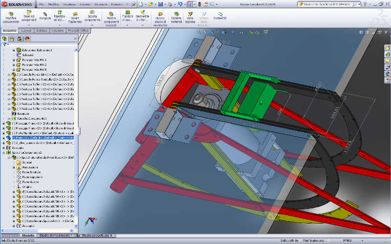
Some pictures to document the move from Sketchup to Solidworks. Although I am a very beginner and I have still many things to learn, SolidWorks compare to Sketchup like a race care compares to a toy car
18 March progress
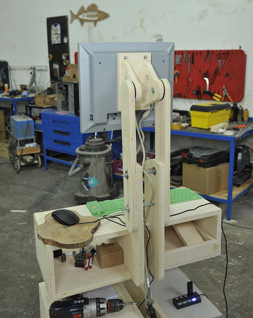
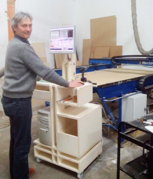
Solidworks ... well know it's my everyday program, so many things still to learn, but it works very well for all my projects and it does export hassle free in all format I use, DXF,STL ecc... The latter pictures in gallery document the design progress made for the "make something big" assignment, were I built a versatile Pc Desk, some accessory like knobs, handels and the usb hub retainer were also designed, exported in stl and 3D printed ( I found the 3d printer very usefull for this kind of things)

Go parametric !!!
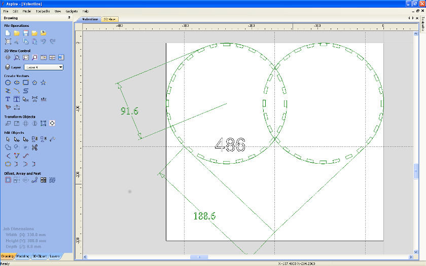
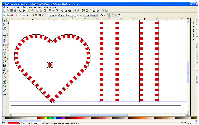
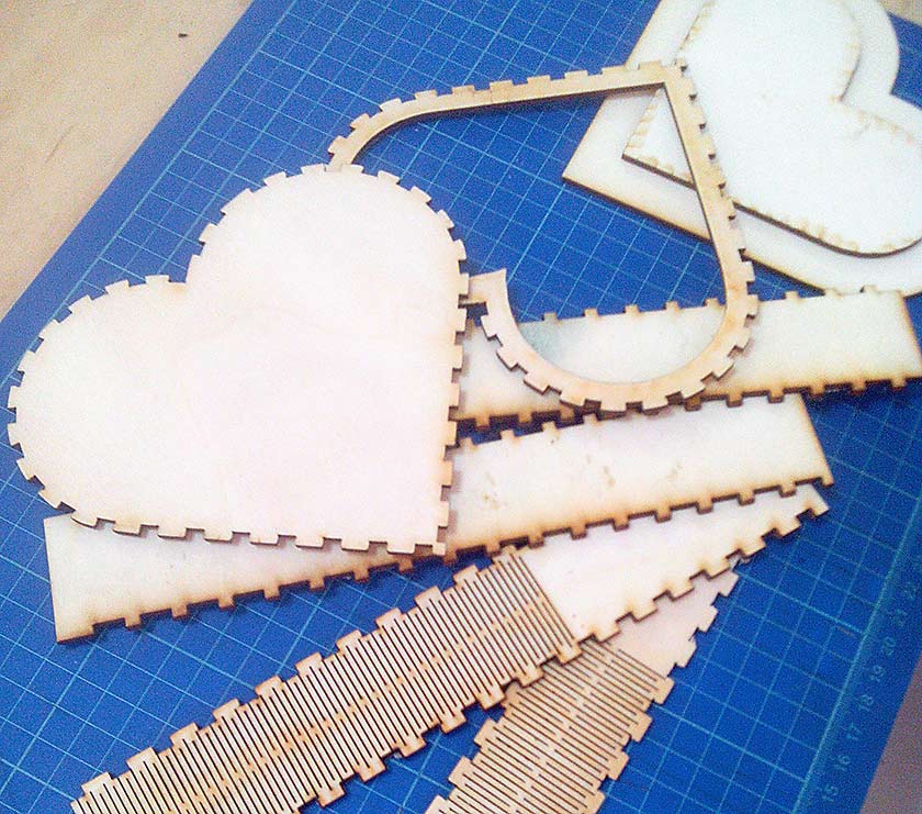
I started this week assignment with a tough thing to design: a heart-box with press-fit joint and kerf bending. My software learning curve is very slow :-( so I started with a program I know well:Vectric Aspire and I get the job done!
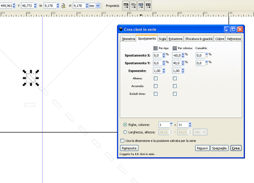
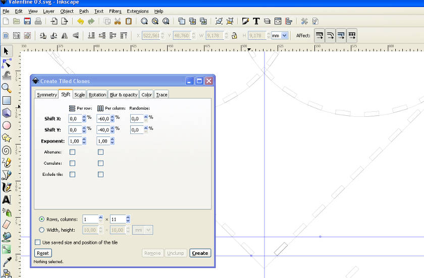
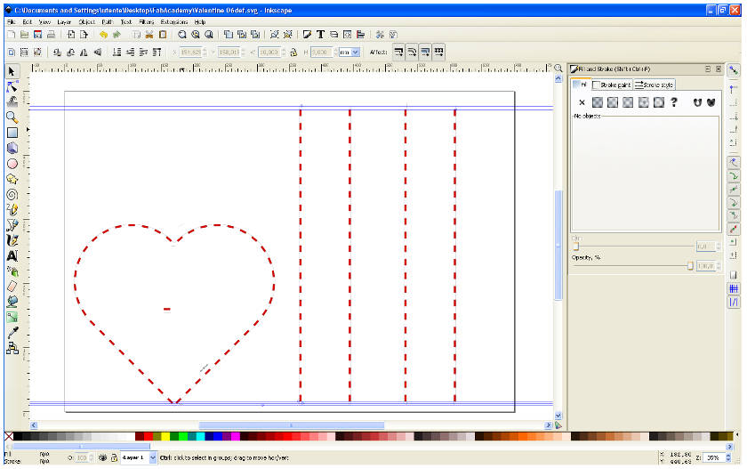
Then I thought that this kind of work need to be controlled parametrically to easy change dimensions without doing a totally new design. I think Inkscape with the clone tool could do it, my plans is to learn how to do similar things also with Antimony and Solidworks, but as I said .... my learnig curve is slow.
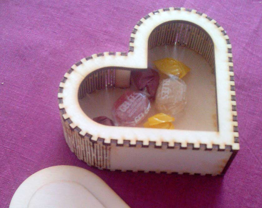
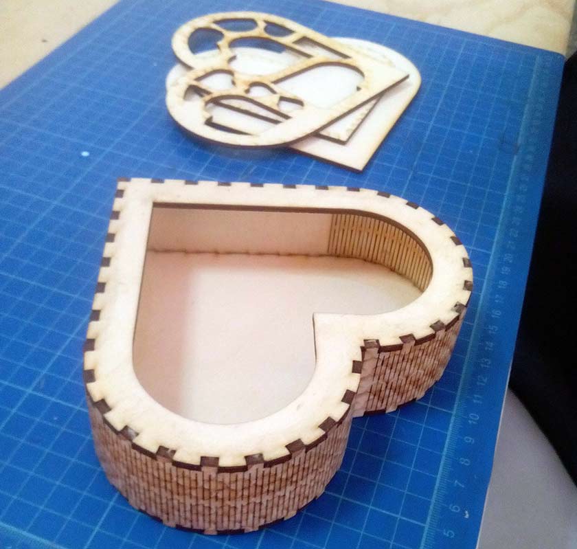
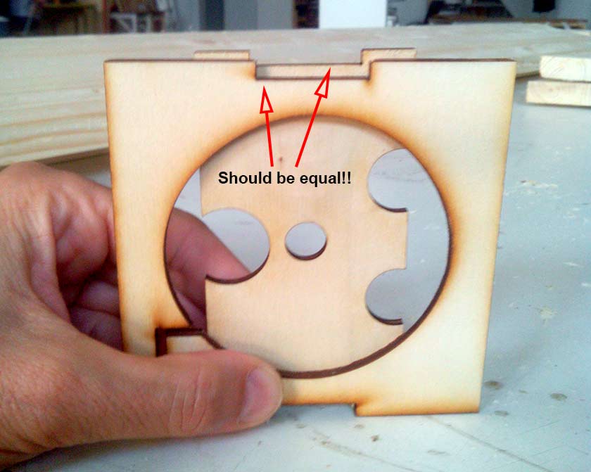
Although I'm still in "beta testing" phase, the cloning procedure worked well. I'am able to do fine adjustment without starting a new design, the result is quite good but better settings are needed. I choosed to have a different size for male/female joint, this is a nice feature, but much more complicated to tune with Inkscape (at least with my knowledge level). The kerf bending is nice and create no problems it's easy to design. The press-fit joint precision of the curved part is a bit different from the straight parts of the heart, I have to think who is responsible of the problem and how to solve it.

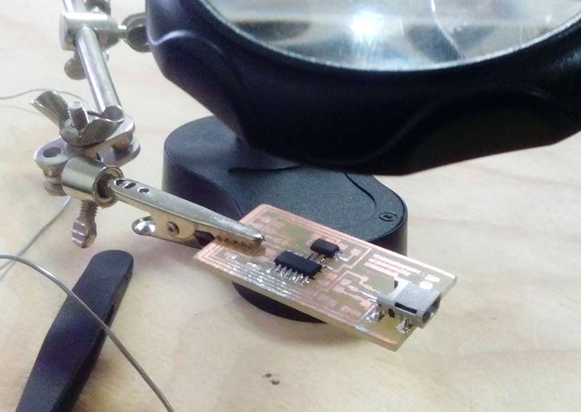
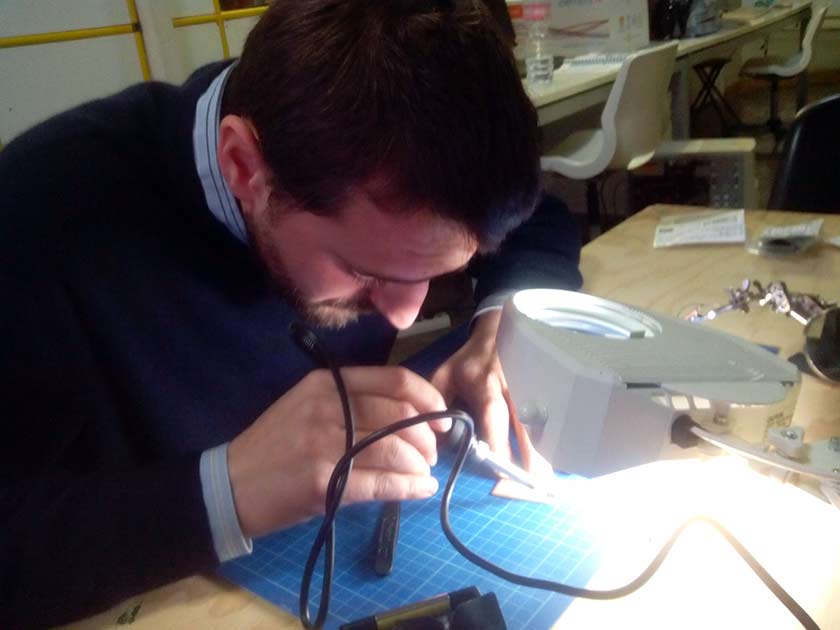
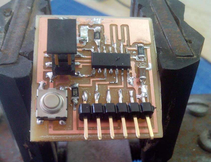
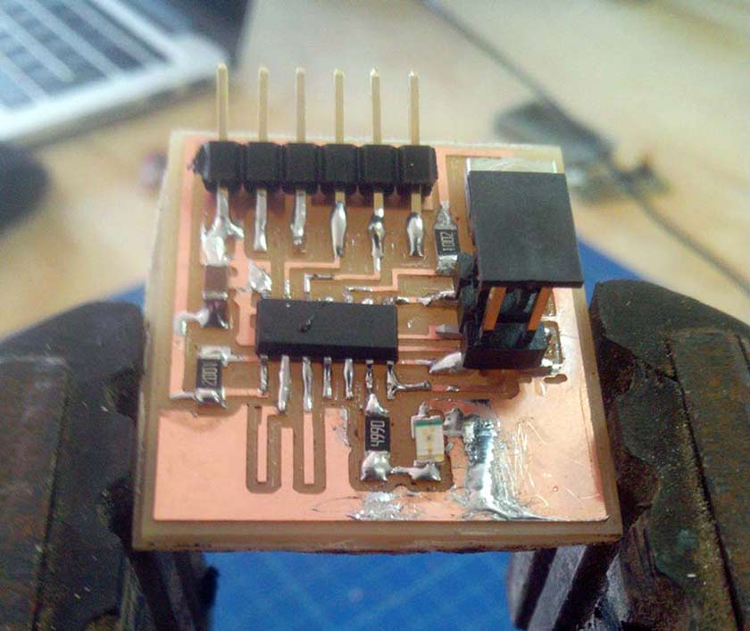
Years ago my experience on welding circuit "was" huge .... but time has passed by: surface mounting and micro components, a such a different game ... the circus of "jumping fleas" (diodes) :-) To work without problems at lest three hands are needed, one for the iron, one for the tin and another to hold the componets in place. Anyway the biggest problem encountered was eye's "seniority" ... two pairs of glasses and lens magnifier :-).
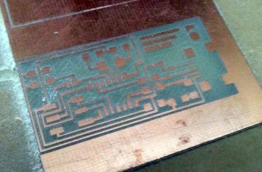
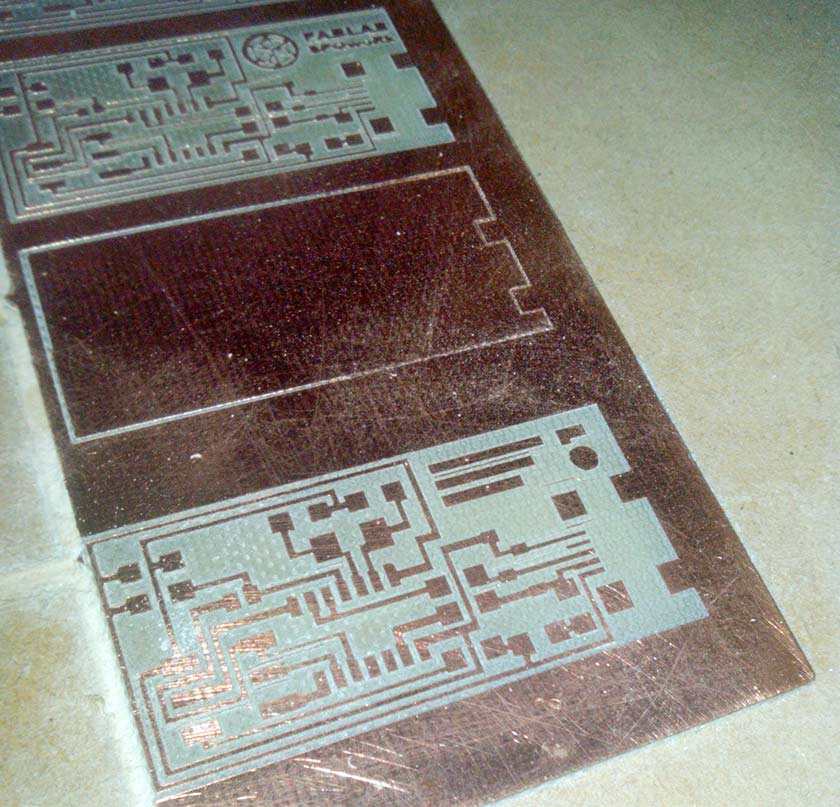
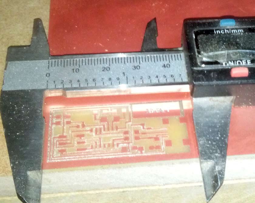
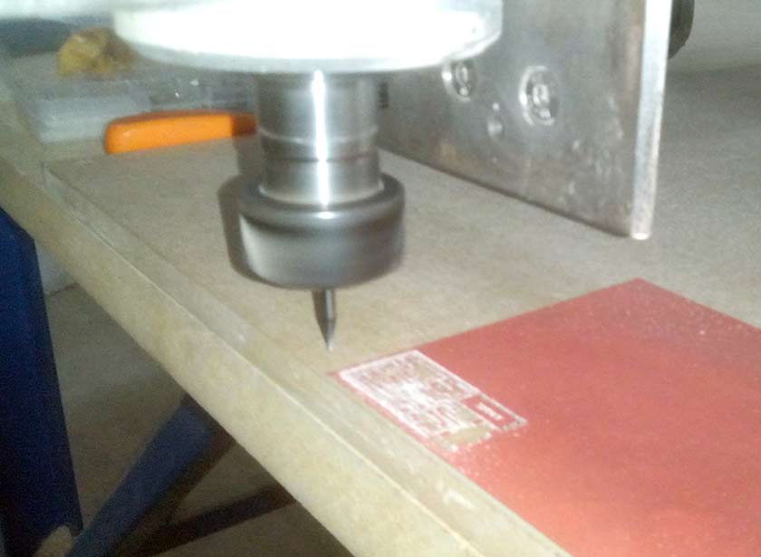
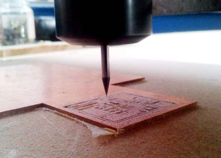
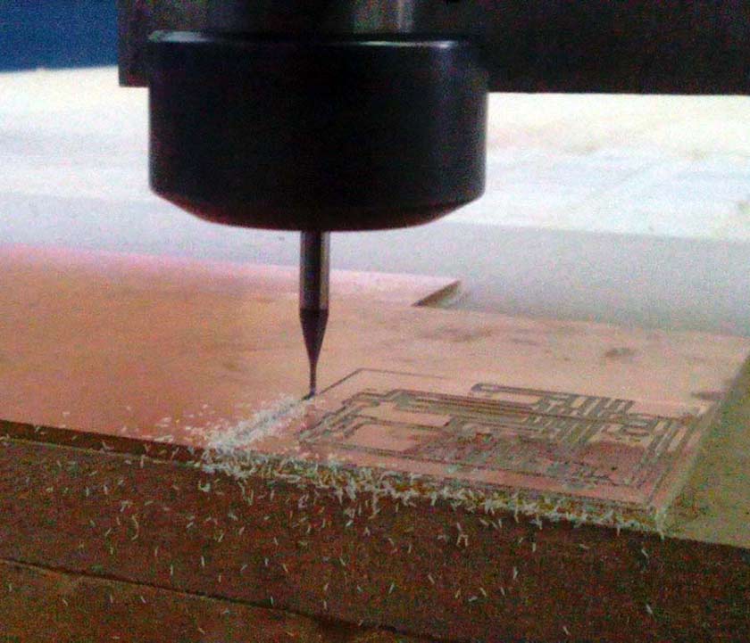
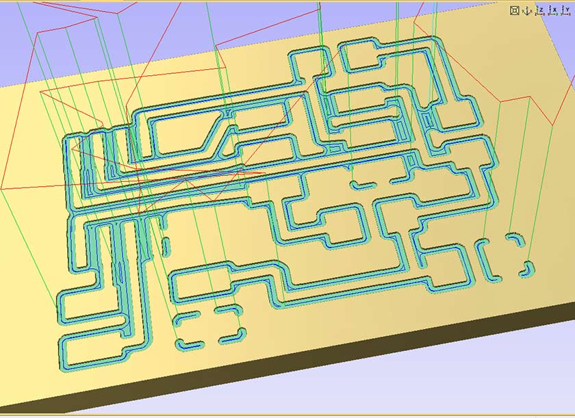
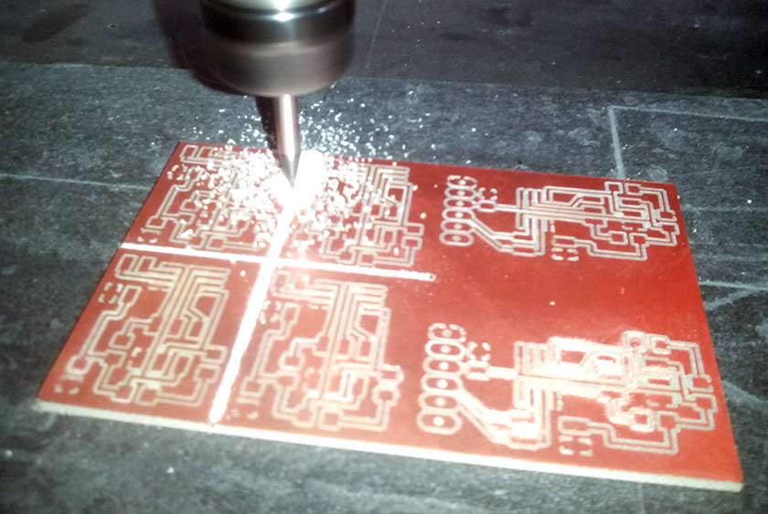
The circuit was milled with a no brand cinese mill that I converted to work with Mach3. The precision needed was much higher than I thought, the difference of 0.01 mm was needed to have a beautiful result with the 20° 0.2mm engraving v-bit (the 1/64 end-mill was not arived still. I used an 30mm MDF board as support without surfacing it (which would have been a better thing). The procedure to mill the circuit was "adapted" to my experience. FabModules has no drivers for our machines (all controlled by Mach3), so no PNGs ... I need a vector file !! With Inkscape I converted the PNG in vector with: Path/Trace Bitmap, exported in DXF and loaded in the Vectric Aspire CAM and with the pocket toolpath we had a g-code for Mach3 which worked very well.
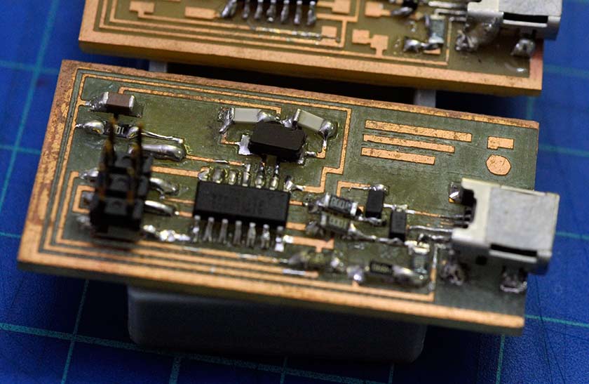
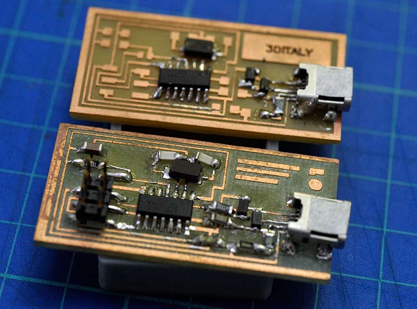
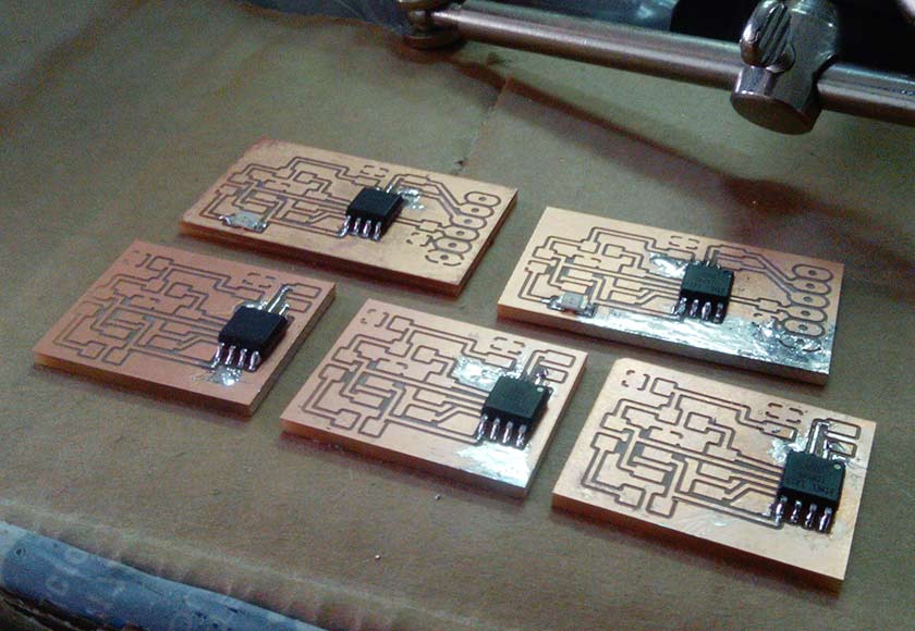
It took almost half a day to solder the small board, it did pass the smoke test, but Didn't work. After a carefull inspection meanwhile another circuit was milled I found a small diode was inverted. The soldering process of the second board was quicker (experience :-) ) some trouble on installing the correct drivers, but this time it worked perfecly ! I managed also, with a little damage to the board, to unsolder a resolder the diode and ... yesss !!! also the first board worked well !
The Gentle Giant Our small mill gave some electronic problem due to interference on the PC signal ... the result was a crazy Z axis which bumped to the base, broke the bit and the collet holder was damaged ... Antonio was still missing his board ... so we tried to use our 3x2 meters CNC router with the 2.2 kw spindle :-).This time we used the 1/64 inch end-mill I was so scared to broke the costly litle bit, but the job was perfectly done at first try. I used a conservative 100mm/min feed rate and 80mm/min plunge rate. I think I cannnot hide my boredom anymore if someone is going to ask about precision of my big MechMate.... :-)( p.s. the 3d Italy's board done with 1/64 end-mill bit and mine, milled with the small machine and v-bit)
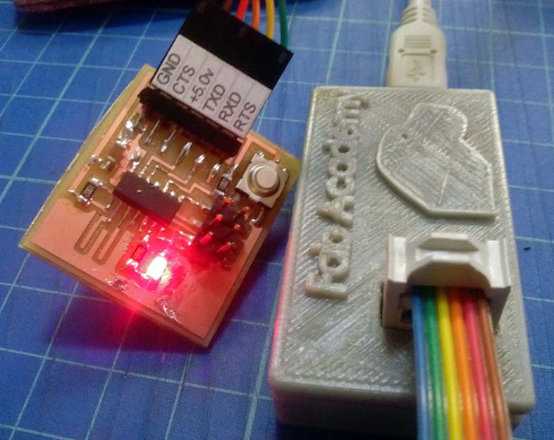
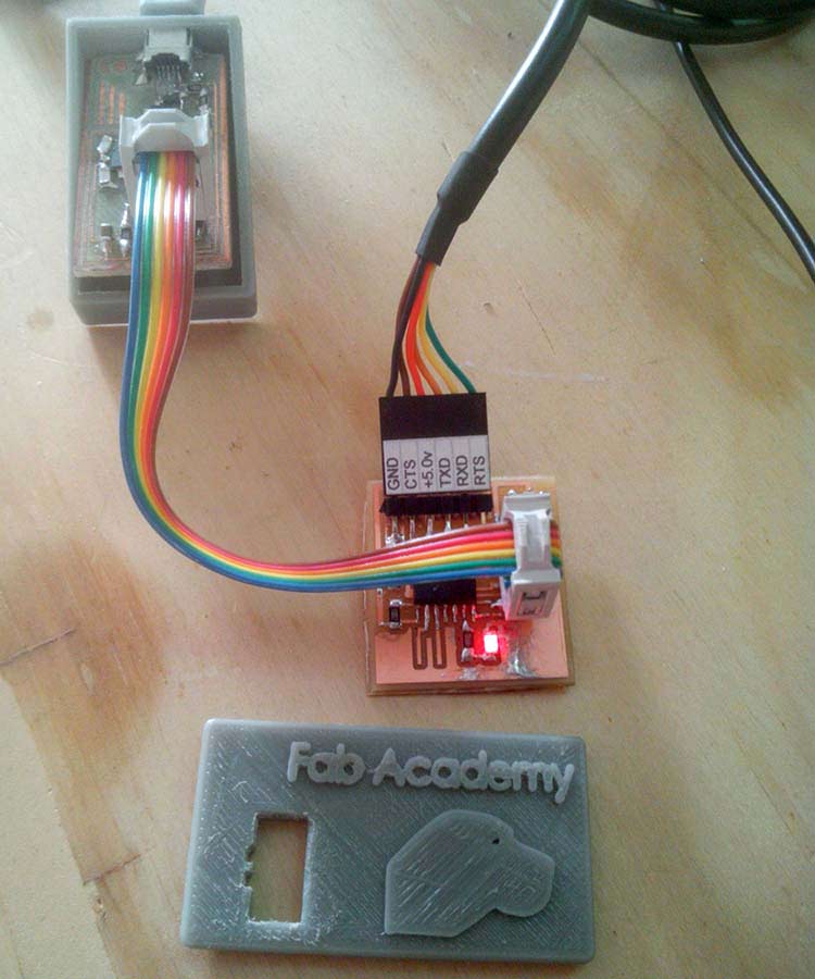
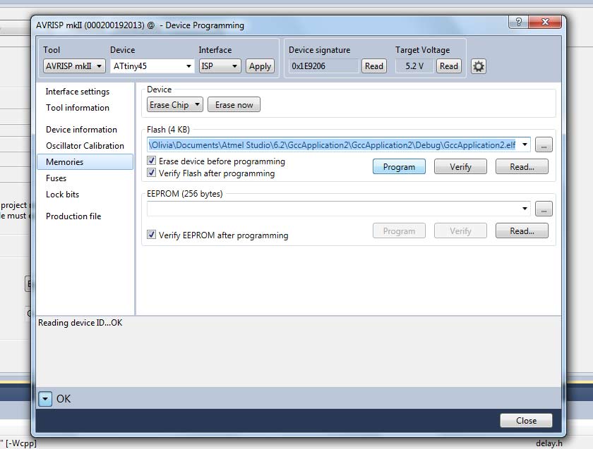
Initializimg the FabISP:
The Atmel MkII programmer was the device we used to "bootload" the FabISP in-circuit programmer, The software used was Atmel Studio.In "Device Programming" I checked the "Target Voltage" Read (5.1V) , then "Device Signature" Read, then switched to "Memories" tab then I navigated to the firmware folder and selected the ".hex" file and hit the 'Program' button. The "verified" message confirmed that the device was properly programmed.
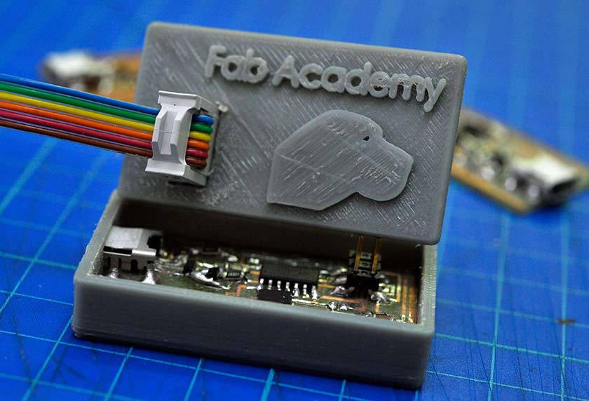
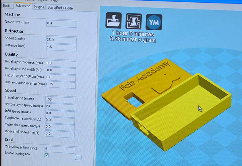
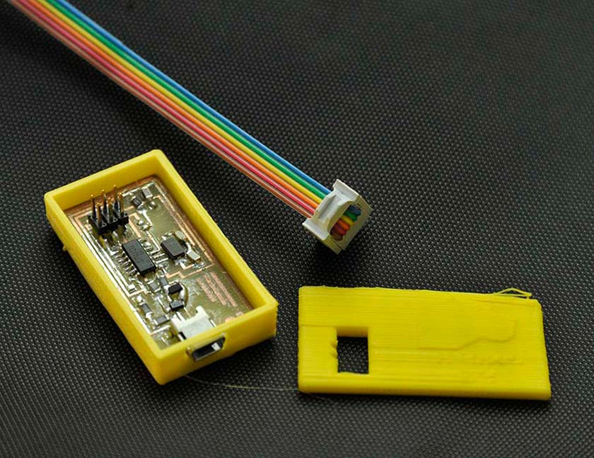
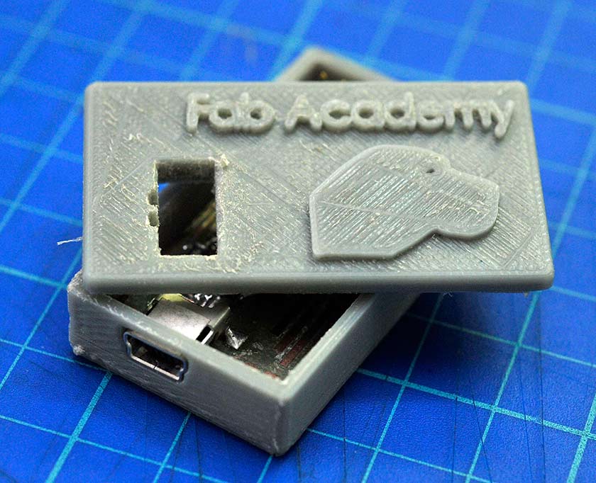
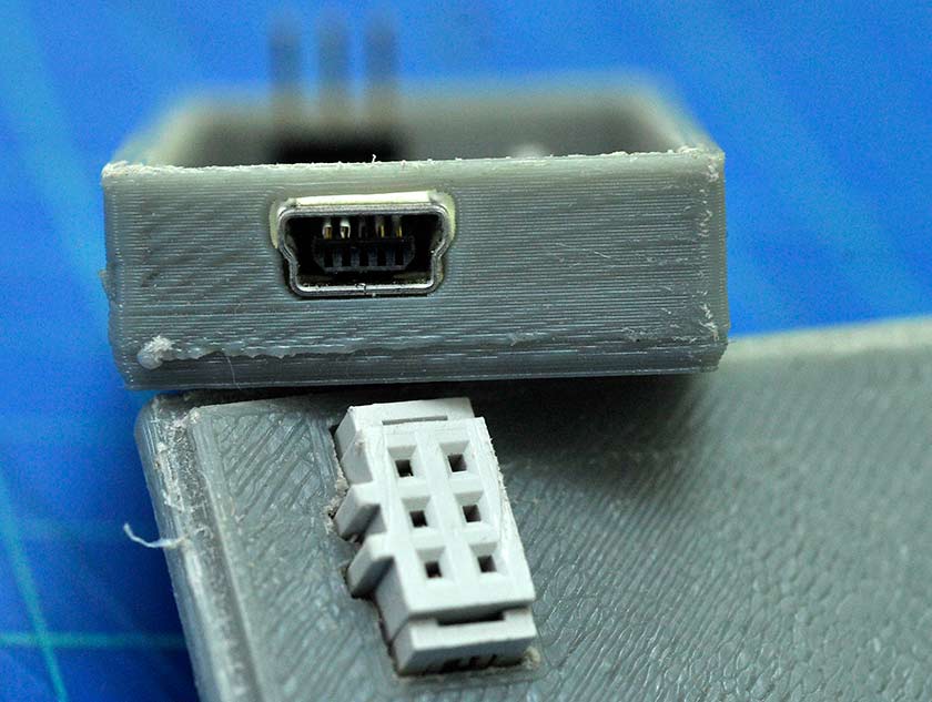
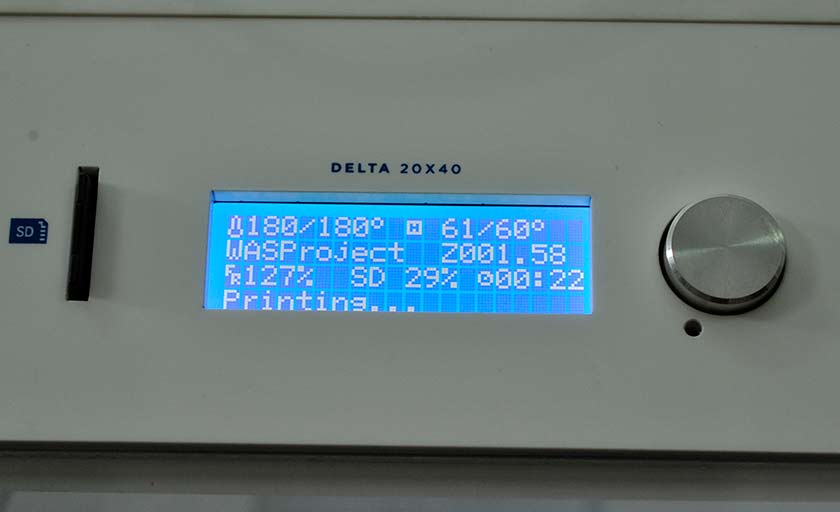
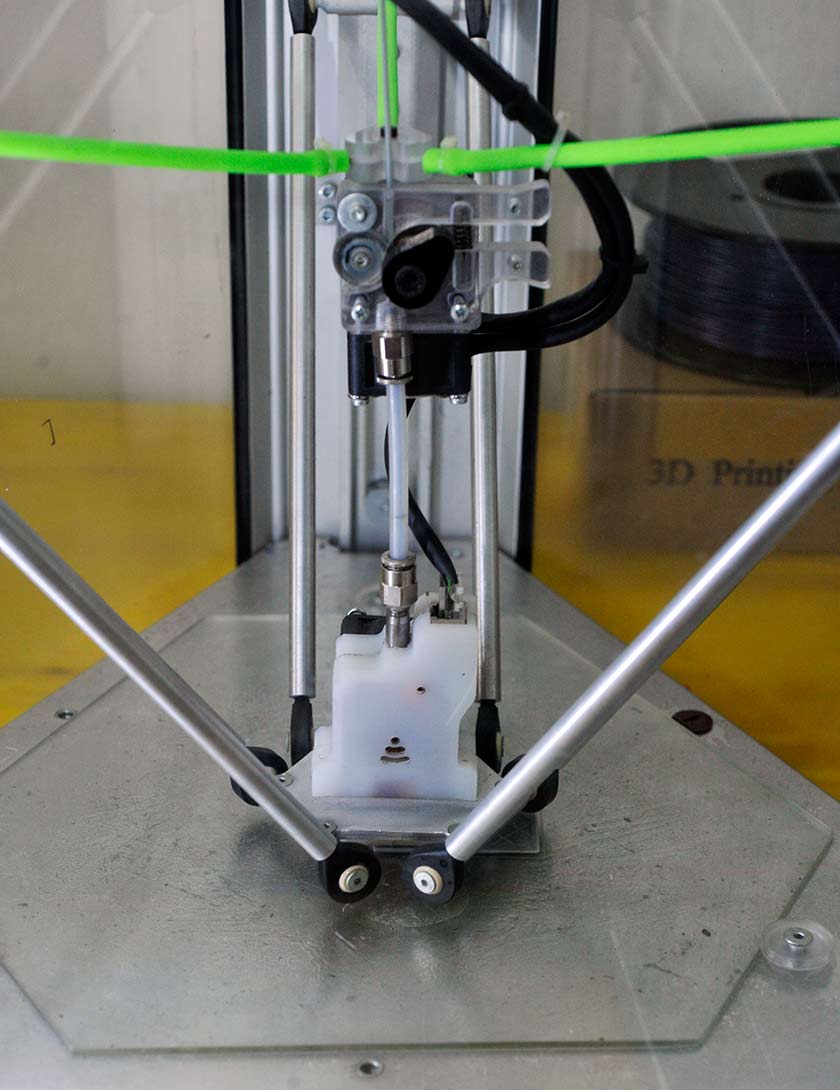
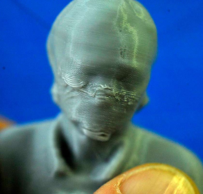
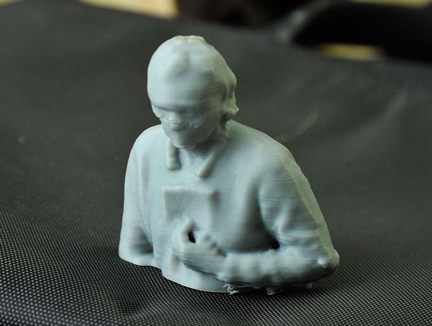
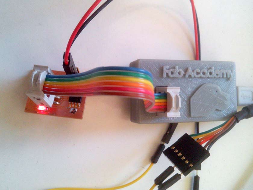
The Little Box During those days I made some progress with Solidworks, I love this program ! I wanted to test how precice is the 3D printing so I designed the box tight to my board, I also used the dxf of the board to see the placement of the mini USB conector and the Mole conector, I downloaded from the supplier site the 3D models of those conectors, and used them to have a precise idea of the dimensions. The parametric nature of Solidworks once you have a minimum of familiarity is fantastic, I was able to change some wrong dimensions in a flash. I exported the box in .stl and opened in Cura. The first try with a prusa i3 was an insuccess, I did not heat the base and the box detached from the base. The second try was not perfect but succeed (yellow box in pictures), the box was a bit larger so was the USB hole, the logo on the top quite cancelled ( I decided to scale it up a bit then ). The third try was made on a Wasp Delta printer. The result was nearly perfet ( just a little smaller that designed ) the final box ( gray ), the conector and mini usb perfecly fit ! 3D Scanning The first test was with Kinect and Scanekt
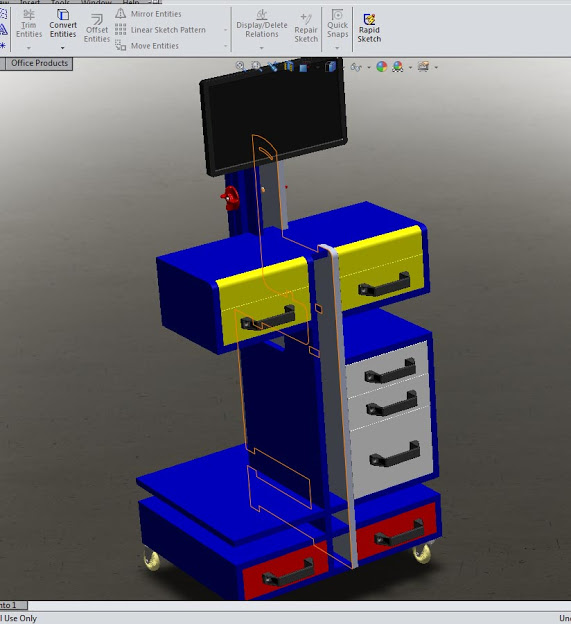
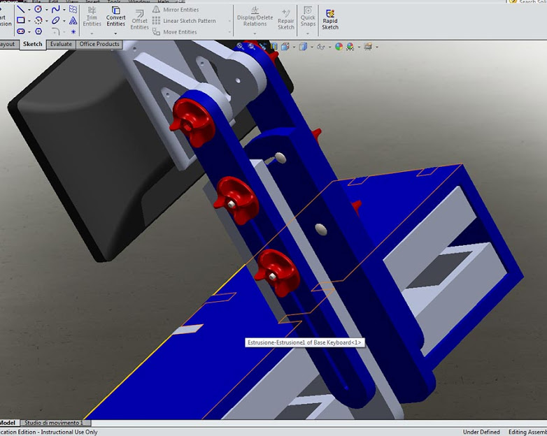
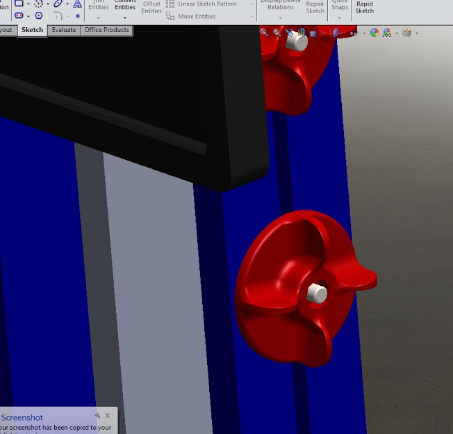
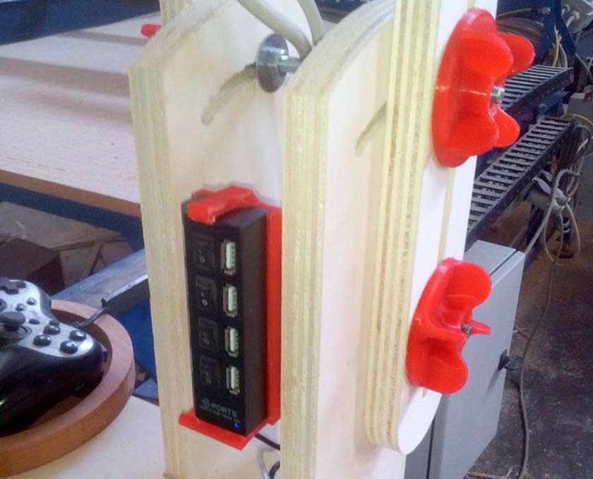
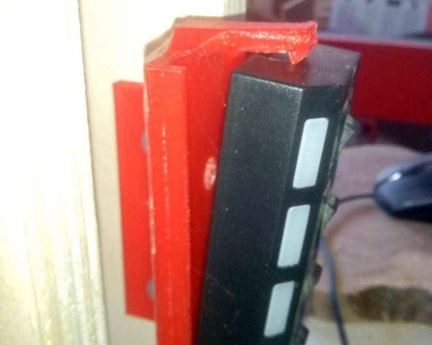
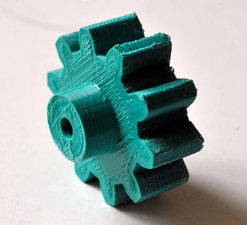
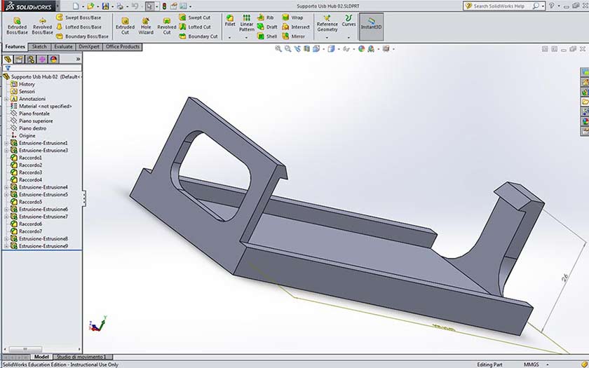
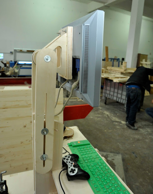
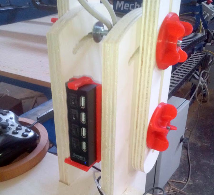
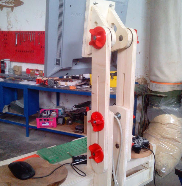
18 March Updates The "make something big" assignment needed some parts that are perfecly suited for 3D printing like the threaded knob to block the position of the monitor, I used the knobs also as a model for Moldig. I also needed a support for the USB hub that should be located in a comfortable position, I designed with Solidwork a support that as some spring tensioner that allow an easy remove of the hub.
Following Fab Academy Eagle tutorial it was easy to begin circuit design, but my result did not satisfy me for two reasons: the first was the look of the circuit, such a simple style :-) the second is that the simple style is also milling time (and end-mill bit) consuming, you have to remove much more material. Eagle has a very simple command: ratsnest ! it creates a ground plane design which gives better reliability, and in the same way you can "fill" with copper other areas. This is my procedure: Step one: Start with a board where you have routed all the signals except ground. Choose "Polygon" tool, be sure you selected the correct layer in the Parameter toolbar than set "width" and "Isolate" values. This is the recommendation from Eagle's help menu: "You should avoid using very small values for the width of a polygon, because this can cause extremely large amounts of data when processing a drawing with the CAM Processor.The polygon width should always be larger than the hardware resolution of the output device. For example when using a Gerber photoplotter with a typical resolution of 1 mil (thousandth of an inch), the polygon width should not be smaller than, say, 6 mil. Typically you should keep the polygon width in the same range as your other wires" I chosed 0.4mm (millimeters). Isolate value determines the distance between the polygon area and the other signals on the same layer. Make sure this is larger than the minimum trace your mill bit is capable. In this example, I chose 16 mils (mils is another unit dimension, it's equal to 1 inch/1000).. To mill the circuits, our small mill was hurted and the spindle axis was damaged ... so we tested the other router mill we had ready ... "the Mechmate" 3x2 meters CNC Router with it's 2.2Kw inverter motor ... a real giant ! well it worked as a very "Gentle giant" all of our pcb board were very well milled and no broken 1/64 end-mill !
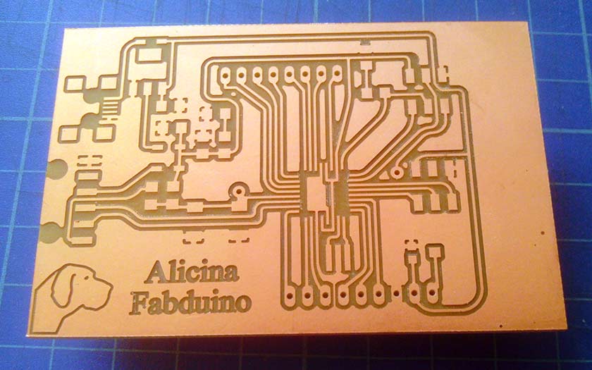
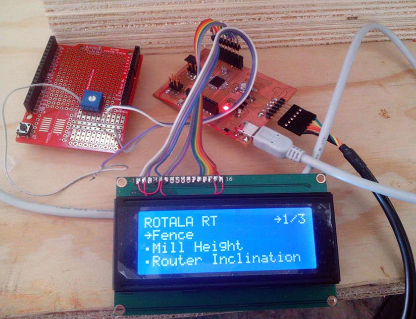
13 of May Update The vesion 2 of my Fabduino board is milled, The improuvement over the v1 is the possibility to connect directly an LCD Display, control the contrast with a 10k pot and give directly the +5v taken from USB.
May Update: Deeper understanding !!
The inspiring work of Daniele Ingrassia student of Fablab OpenDot Milan pushed me to a deeper understanding of what I'm doing.
One of the questions was: why on the improvement list of his Satshakit he states "crystal instead of resonator" ? Why a crystal is a better option compared to a ceramic resonator ?
This is the answer I found:
"gbarry": "An oscillator is an amplifier circuit, with feedback so that it oscillates, and a "frequency a element" that keeps it oscillating at the desired frequency. A crystal can be made for a precise frequency, and it will drift very little if the temperature stray capacitance changes. It is also very efficient and requires very little power to keep it oscillating. Crystals are usually made of quartz, and you pay for all the above features.
Resonators are made from ceramic elements rather than quartz. They do not hold their frequency as well. This may not be important for a microprocessor, but will be important if the circuit is used in a radio, a clock, or other timing-critical applications. They cost less and so are used where stability isn't as important."
Another opinion "Guillelm Planisi":
Resonator accuracies are in the order of 0.1 to 1%. Enough for USART comms, and for some time measurements, but not enough precise to keep time by RTC.
Crystals have precisions in the range of 10 to 50 ppm (parts per million), much better than resonators, so they are good if you need pretty accurate timming measurements and/or RTC.
BTW, RTC accuracy can require much more precission than many other applications. 5 secons per day may be too much to be accepted, and this is about 57 ppm's.
And a here you find deeper explanation with comparison table.
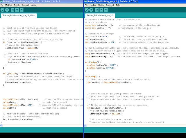
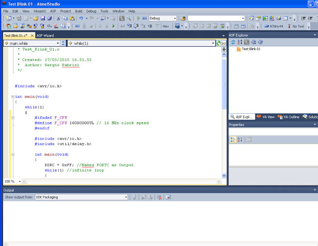
When I heard about Arduino the first time, I was not very impressed, many of the examples were about turning on and blinking a LED, I did not find very interesting and quit without understanding what was realy going on. But then I fell on Arduino Dishwasher hack and I started understanding the real possibilities af a circuit like that. "Programming" with Arduino IDE is not very hard once you understand the basic structure, and using copy and paste I was able to create a new code combining differents parts code. I installed Atmel Studio, but I was not able to understand the basic grammar for the moment, and combining differents codes was not successfull.
The 650 pages of the Atmel ATmega328 are somewhat intimidating ... my needs were around the information about the voltage needed to operate the processor but also voltage of the logic ports. I designed my Fabduino with the idea to have the possibility to drive any shield, so like the original Arduino I thought it could be a good idea to have both 3.3v and 5v available, protecting the source line with diodes they told me could be a good idea ... my knowledge is weak ... but having received an answer to my request of help, I understood the difference between the general purpose diodes, Schottky an Zener. To protect the source line the right diode is the schottky because it has a very small voltage drop ( tipical ~.1V compared to ~.6V of bipolar diodes). A very interessing data is that the minimum voltage supply is proportional to the operating frequency "Speed Grade:0 - 4MHz@1.8 - 5.5V, 0 - 10MHz@2.7 - 5.5.V, 0 - 20MHz @ 4.5 - 5.5V". At page 160 I founded useful information and explanations on SPI interface.
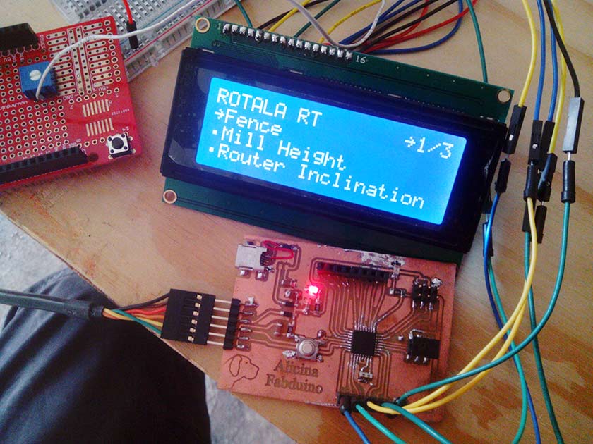
My first code is made on Arduino IDE, my programming skill are slowly growing I start better understendig some part of the code I was only copying. My code is a bit ambitious for my skill: I want to use an LCD display with a menu to choose different functions, set some input value with the use of an encoder (well ... 4 bottons for the moment) execute a command and make a stepper motor move the distance I choosed. I very happy for the general results, although small part of the code has to be tuned.
Rotala Code.zip (WIP)
Rotala Code02.zip (new)
Internet of things ? Well for me it's internet of people !
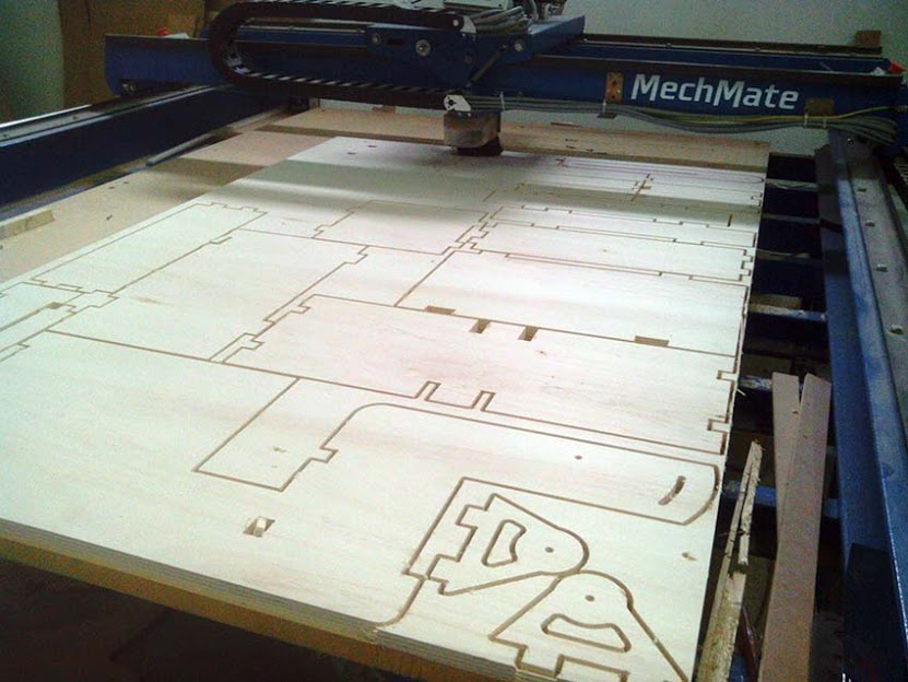
I will be 52 this year, so I think I made some experience in my small world ... My greatest Master is a person I never met, he lives in country I have never visited: South Africa, which is very far from mine (Italy), his name is Gerald Dorrington and he is a mechanical engineer, his company Mechlift is the largest manufacturer of bin lifters in Africa. He have run a 8'x4' ShopBot since 2000, when his son Sean started a CNC cutting service "Camcraft" in Cape Town. After 4-5 years the growing business of "Camcraft" needed some machine upgrades, and Gerald who already had modified his shopbot decided to start with his own project The Mechmate and built a forum with the plan and all the info to help building the "beast" (well now in SPqWork FabLab we call it "the Gentle Giant" :-). The Mechmate was a totally Open Source until Gerald quit the forum after 5 years of generous daily activity teaching with immense patience to many some of his huge knowledge. One of them it's me.
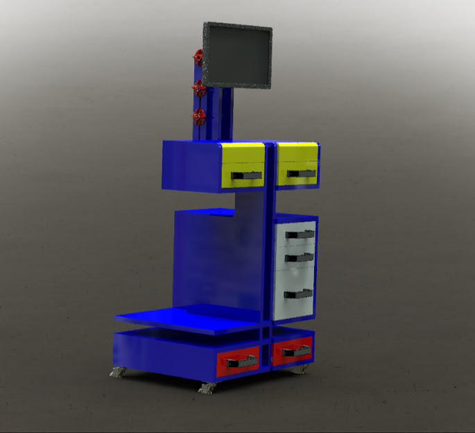
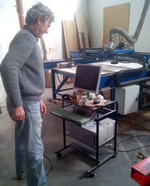
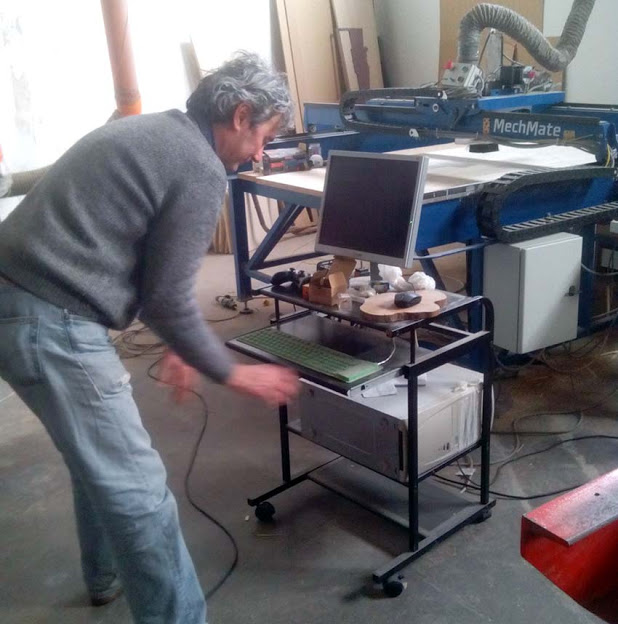
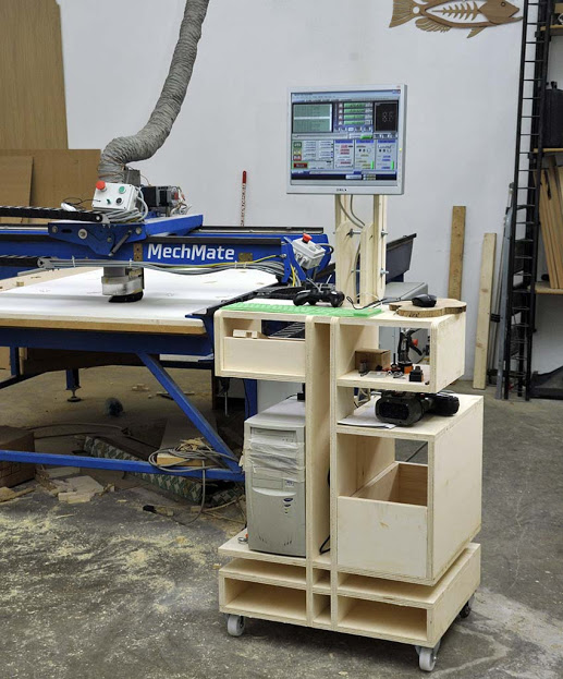
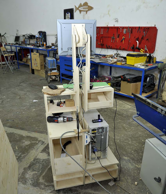
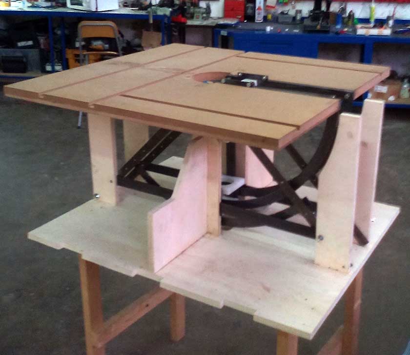
For this assignment I decided to build a PC stand for the CNC machine, the height is the primary factor, I need to have a correct standing position while I use the CNC machine, and the monitor should be easily positioned to a confort distance. It will be nice to have the possibility to move the whole thing in a rest position the closest to the machine. To design the desk I started a preliminary design in sketchup, wich I think it's very fast and easy if you still don't have an idea of what to do. When my idea was a bit more clear I choose to do the project in Solidworks. I am still a beginner but I like the way you can change things without starting again. Giacomo Falaschi anothe Fabacademy student from Fablab Cascina made his assignment with us he is more advanced than me in solidworks and his assignment work is totally parametric, he used the "functions" and changing one parameter ( for example the material width) all his project automatically adapt to the new dimension. WOW !!!. I need to learn this !!!.
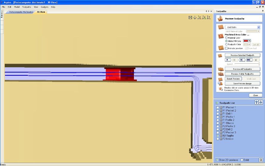
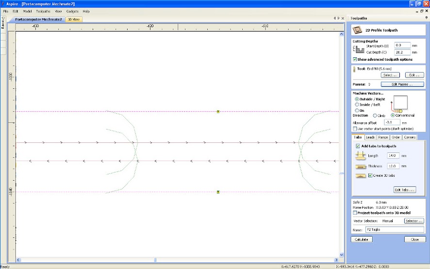
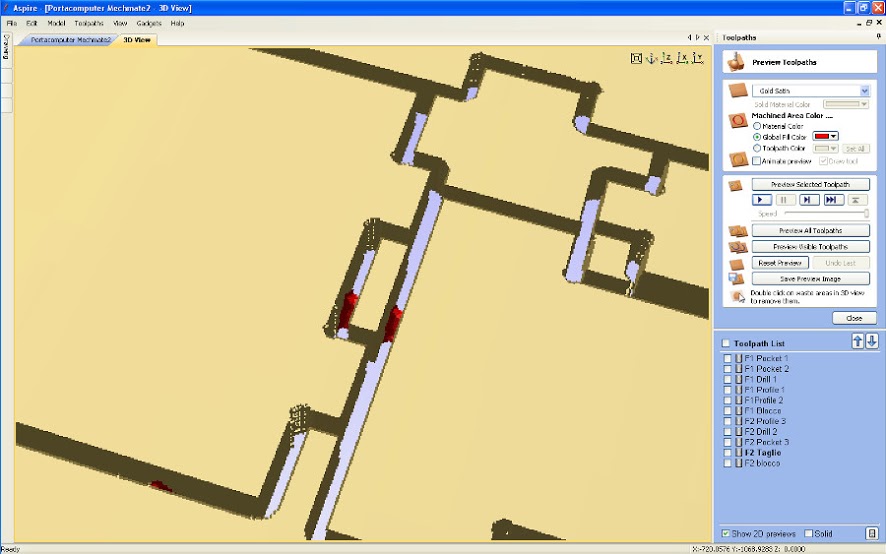
It took me 2 days to complete the design and then I exported all the parts in dxf format which is very well acepted by my Cam program: Vectric Vcarve Pro. Vcarve Pro (used also as Shopbor official CAM) is maybe the simples Cad-Cam I tested and is also versatile and powerfull, his cost is around 500€ and in four years of experience I did not find any better cost/feature performer. One of the greatest fetures is the possibility to exatly place tabs where you needs in a very easy way. As material I choosed an economic 20mm poplar plywood, cutted with a 6mm upcut 1 flute end mill tool with a speed of 3600mm/min and 7mm depht of cut ( generally depht of cut should be equal to mill diameter, softer materials allow deeper cuts ... spindle power is obviously a factor).
Here you can download the solidworks project's files:
Download Pc Desk
One flute upcut end mill are my favorites, the reasons why I prefer one flute over two or tree flutes are: they cost less, they have a better chipload, and generally are more strong. Understanding chipload is the key to better performance in terms of wear and speeds .... this is the Onsrud reference It is the best I ever found. Each mill as a feedrate and rotation speed range, if the feedrate is too slow and/or the rotation speed is too high the mill will rapidly deteriorate loosing his sharpness due to excessive heating ( good chip removal is essential because heat is transferred to chip); if feedrate is too high and/or rotation speed is too slow you won't remove enough chip and the mill will broke or the piece will be moved or the machine will loose steps depending who is the weakest. In my personal experience understanding my machine it's very important. I nedd to know which is the maximum load/speed combination until I start losing steps, and that is material dependant, I've worked flawlessly at 6000mm/min with depht of cut of 100mm !! with Extruded Polystyrene and at 3600mm/min ( 6-8mm end mill 1 flute) with European Beech and Oak but you have to test with your CNC machine (mine is a particulary strong).
A very important thing with CNC routers is the "fix" of your work piece. I use to screw the material onto a 30mm MDF sacrifical layer, to be shure I do not hit the srews I place some guide holes onto my nested CAD where I am shure it's not on the path of my mill, then I export it as a separate Gcode and I run the CNC (tipically 3mm depht it's ok) will all the axis zeroed, the small holes don't move the pieces as the forces are only on vertical Z axis, when all the guide holes are done I use a cordless screw driver to secure the piece (on some hardwood a complete pre-drill could help to avoid wood break). I think this is a very economical sistem and it takes litle time to do.
Other common fixing systems are :
Large Vacuum are the fastest, but at a very high energy cost: an effective large system needs motors in a 7.5-10 Kw/h range ...
Vacuum Pads are very effective on production jobs, particulary when your work needs the complete surfacing of the top. The pad can be shaped to best work with 3D bottom shaped parts ( ex: Surf Boards, Electric Guitars ....)
There is not a perfect solution I think some are very effective on some works but not good for others ... holding down/fixture is an art :-). I had some realy hard times finding a good solution !!,
Tabs Are my CNC best friend, I devoloped some tricks to help my work: the first one is the way I place tabs when I nest many parts toghether, Vectric Cam programs (Shopbot uses Vectric programs with a different name) allows manually placement of the tabs which in IMHO is essential. I place the tabs in front of each other when the clearance of pieces is less than the diameter of the mill , this will avoid that one of the pieces toolpath remove the tab of the adiacent piece.
Dust collecting is essential. There are ways that can help and are more efficent: separators. Separators avoid the clogging of the filter using a cyclonic system that drop most of the dust before going to the filter. There are two concept that can be used by DiYers: one is much easier to build but slightly less efficent is called Thien Separator and a more sophisticated Cyclone designed by Bill Pentz :Cyclone Plans.
... work in progress ... Cutting Tools
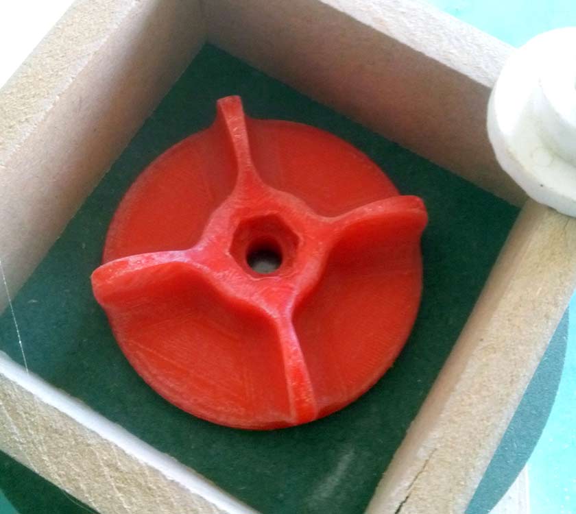
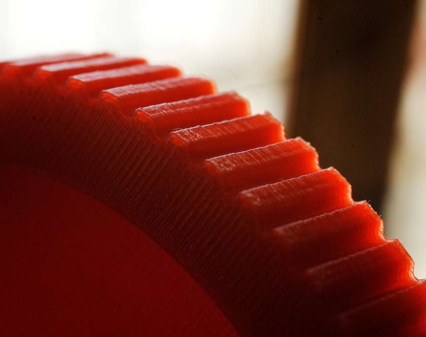
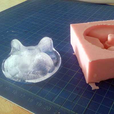
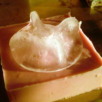
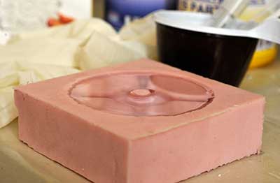
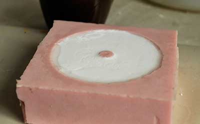
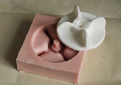
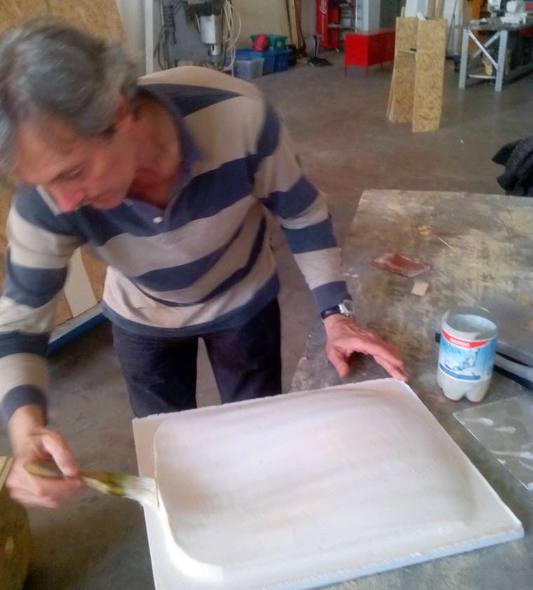
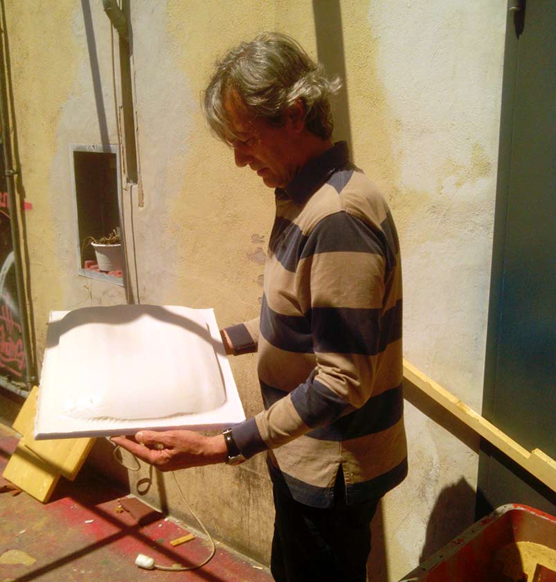
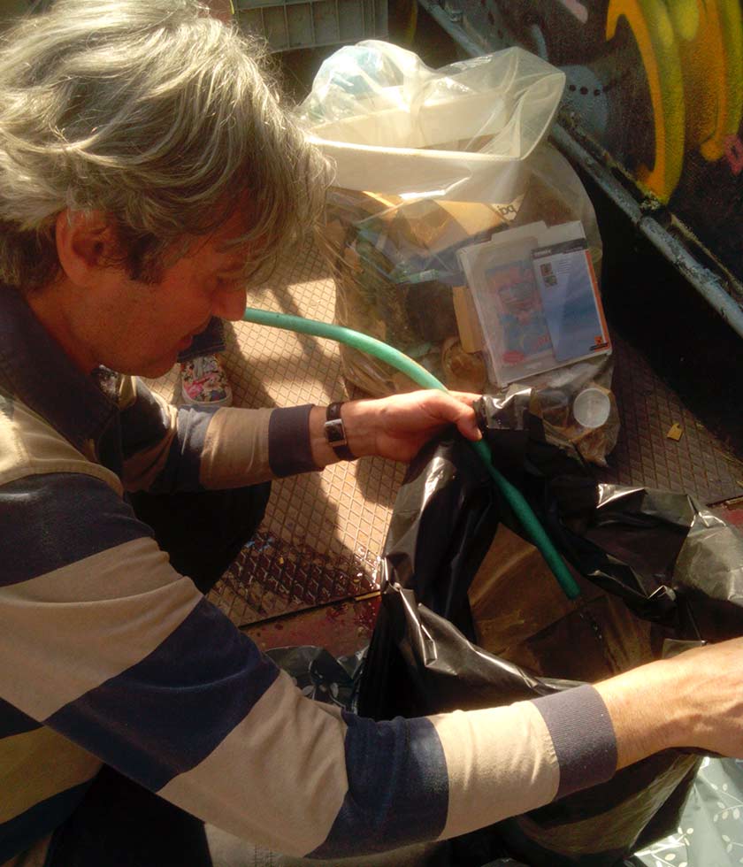
My first idea was to make a mold for some big timing pulley that I need to build a 4th axis ( indexer ) for my CNC, the idea was to copy an expensive 72 teeth XL pulley, and compare the results with a 3D printed one. Unfortunately I'm still waiting my aluminium "master", so I decided to mold the knobs for my Pc desk.
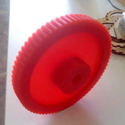
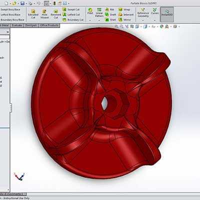

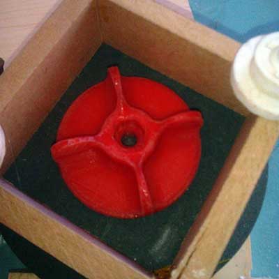
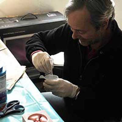
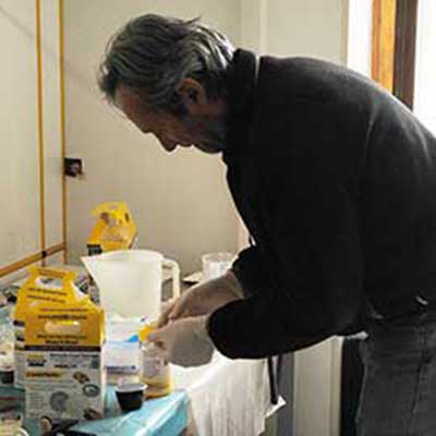
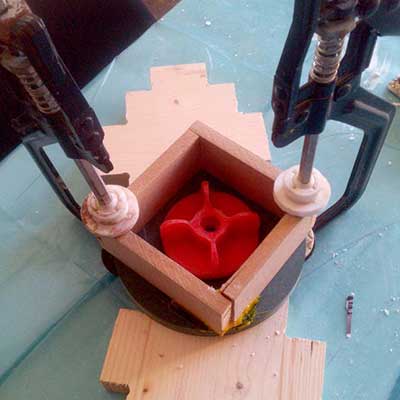
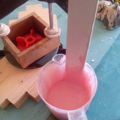
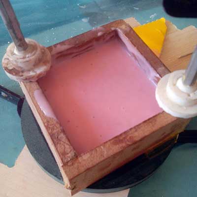
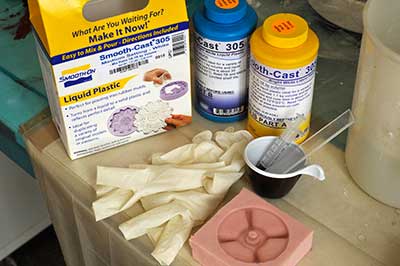
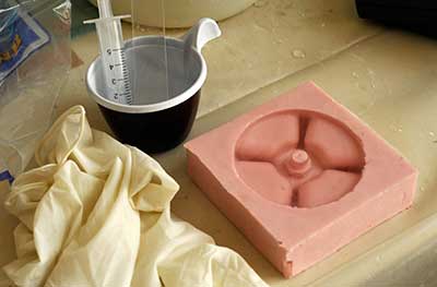
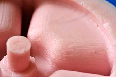
First I tested the mold with water and put it inside a freezer, I obtained an "impermanent" Ice knob, then I used the Smooth-Sil 940, combining the two part in a proportion of 10:1 in weight. the mold was treated with vegetal oil to better separate from the silicone ... which was an error because I used too much :-) and some holes due to residual oil were made. The result is a perfect copy of all the small details/imperfections of the 3D print plus some imperfection due to the excess of oil.
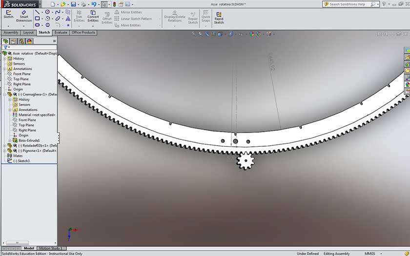
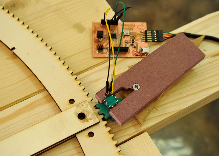
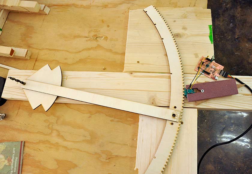
Measurements ... I need for my final project to measure the variable angle between the surface of the table and the mill, this feature will help to make some border joint in a productive and precise way. There are some possibilities to measure an angle, my first idea was to use an encoder with a pinion and a long curved rack with a radius of about 500 mm. After Neil's lesson, I thought it could be nice to try with a two axis accelerometer/position sensor, but with further investigations I realized that It would be very difficult to obtain a precision equal or better than 1 degree ... which is good but I would prefer to reach 0.1 degree, that would be possible with an encoder and the right gears. I also thought to use a stepper motor as an encoder, but with further investigations I understood it's not possible. I designed a basic gear and a curved rack, the size of the teeth was calculated to have 360 teeth on the full circumference and to have one degree each step, a very simple encoder will easily have 12-24 step and that would give me the requested 0.1 resolution.
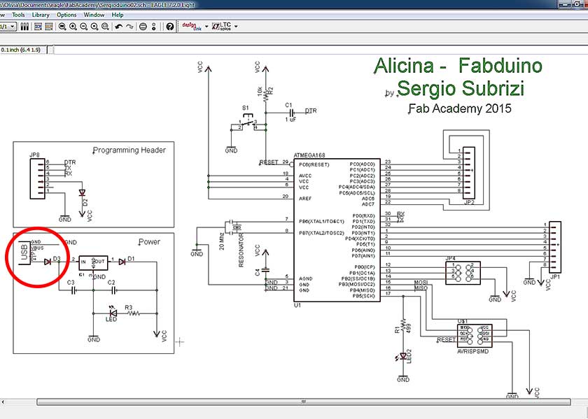
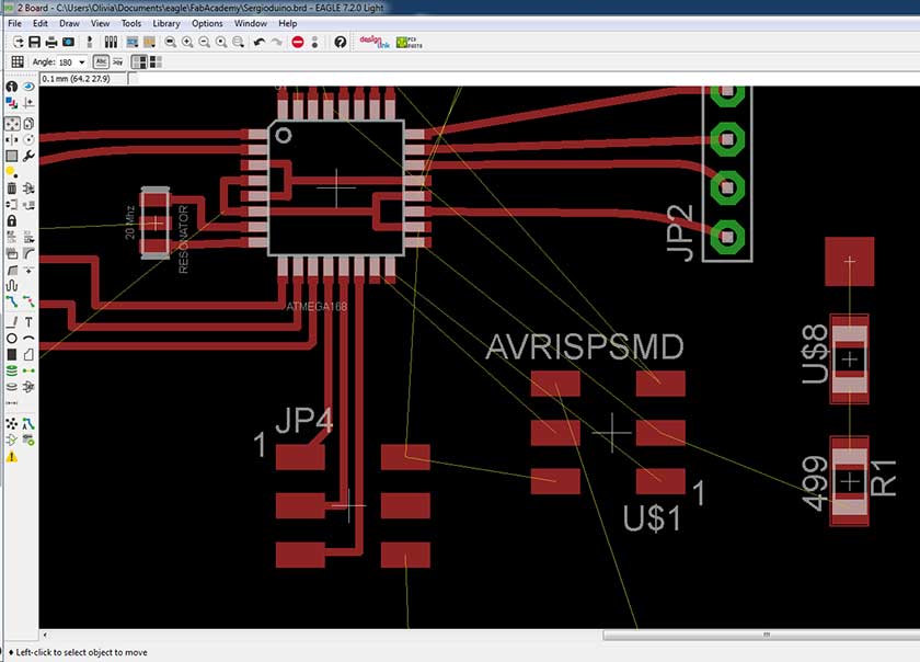
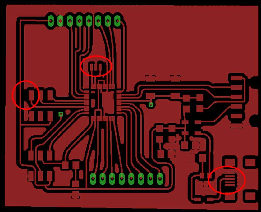
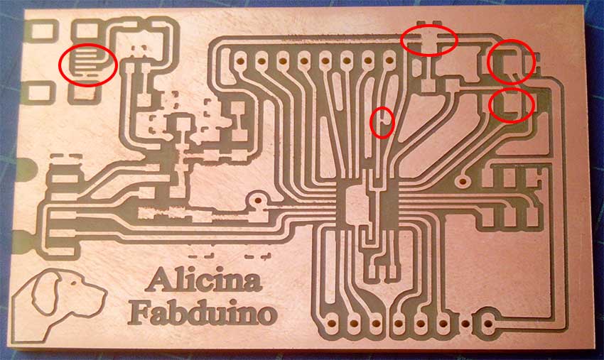
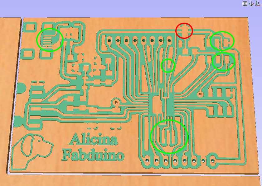
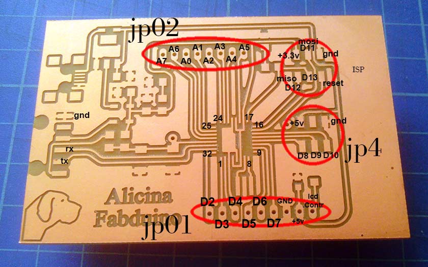
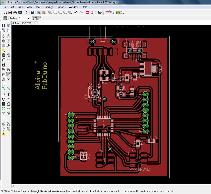
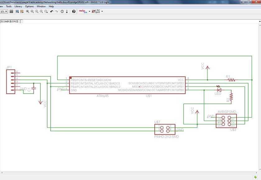
Last thursday I started to think I could never finish this assignment in one week, so I started with a minimalistic work ... "copy and modify a little" what other students did in previous courses ... I was not happy at all, but after a good sleep, I wake up with the motivation with whom I had started the Fab Academy adventure: learn as much as I can, and "copy and modify" isn't the best way. So I started from scratch the design of my Fabduino board with the Eagle software. The beginning was a problem, it was difficult to find the right components in the Eagle library, the design of the circuit was a slow process because my memory on Eagle's commands vanished after some weeks on other assignments. But in the end almost everything was ok ... well except the wrong usb connector and the too small resonator package (red circle = faults).
The routing traces it's a nice game :-) but the real "mind game" is the component placement, I was prepared to use some wire bridges, but only one was necessary (from reset pin to the ISP connector). All the pins of the Atmega328 were conected and in my next revision I will try to make the board Arduino shields compatible.
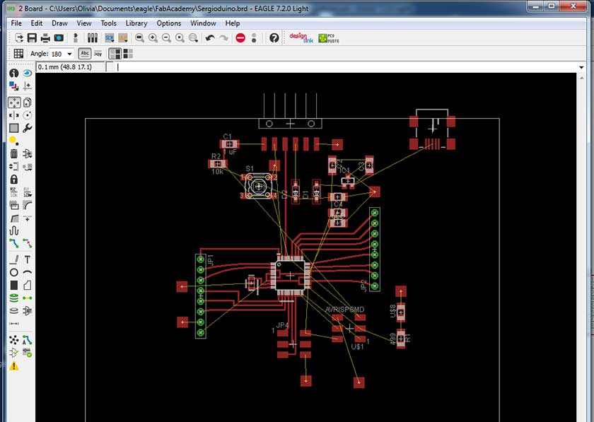
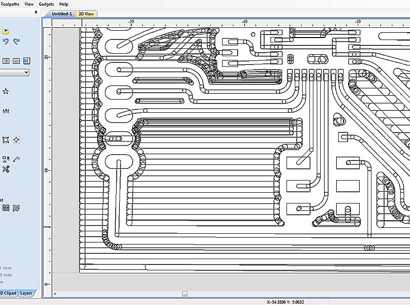
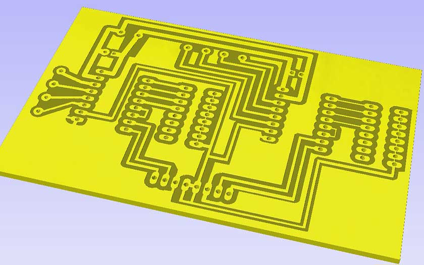
I tried different methods to export the Eagle design: first exporting in dwg/dxf format and then exporting a PNG image at high resolution (1000/1200 dpi).
DWG/DXF and other vector format were very bad and all the vector based programs did not solved easily the problem, a lot of work was needed to have an usable vector file. A better solution was to export a PNG image at high dpi rate and then trace the bitmap in the CAM program some work was still needed but less than the DXF file.
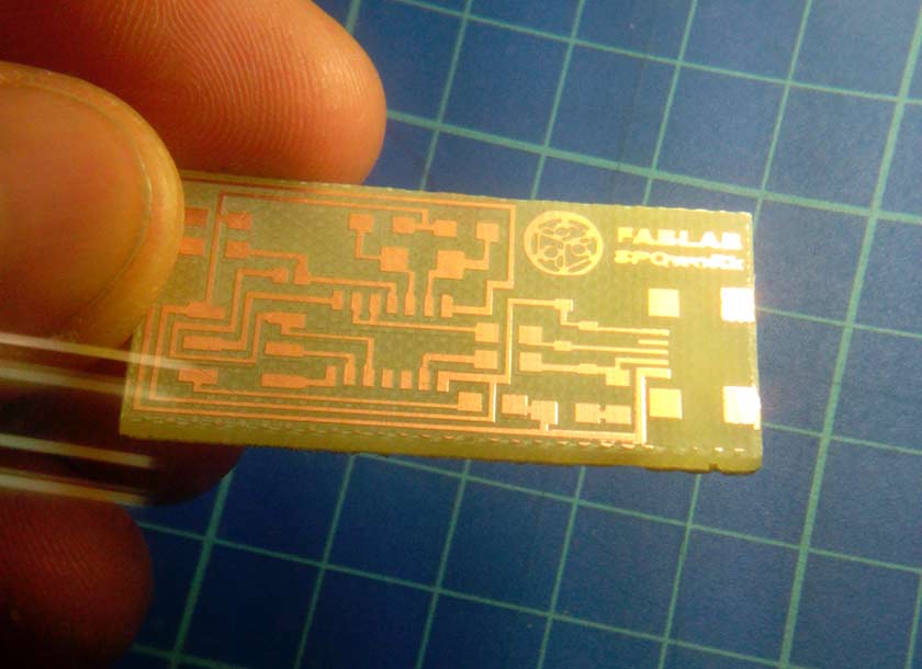
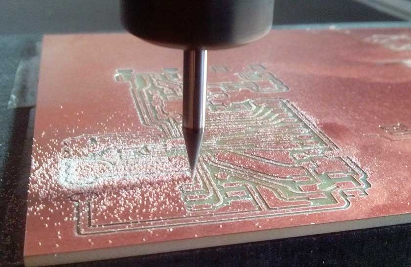
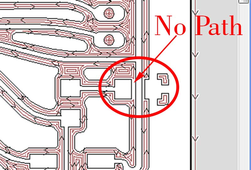
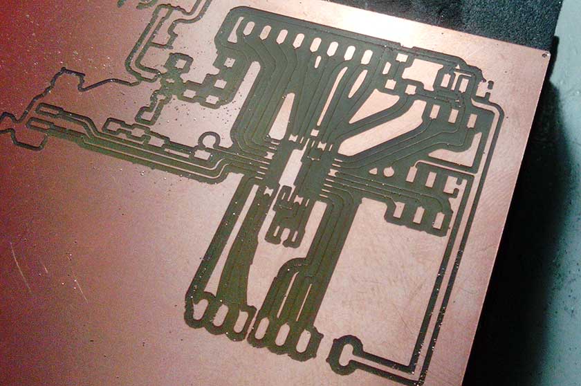
A collection of errors were made, few designing the boards, some on the CAM process and some on the milling process, the first milling try was with an engraving v-bit 0.2mm flat tip 20deg, the preview results were better than the 1/64 inch flat-end mill but as you can see in one of the images, the v-bit was ruined and cutted much larger than expected, another problem with v-bits is that trace dimension is affected by depht of cut, so a precise Z zero and a perfecly leveled base are mandatory. Using the 1/64 end mill is easier but I had to modify some traces and pads where it was not possible for the mill to pass through. Finally the result was great with just few correctable errors.
The soldering process was tricky, but now I manage the small component much better now. After a carefully check, I eliminated some few short circuits before the smoke test, except one which was shorting VCC and GND under the led on pin 17. Luckily no smoke, just a diode too hot found touching the board with a thumb.
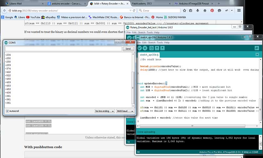
Even there, finding a working code was hard. The working code I finally found, did counted the impulses on the serial monitor, but I couldn't get any conversion to my desired unit: the degree. .... still lot of exercise to do ... work in progress ....
 t
t
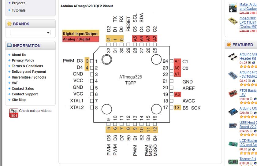
With my fully connected Atmel 328 - Fabuino I'm going to control a stepper motor. Something I will need on my final project. For the moment I will use the Arduino IDE, C++ is still out of my range for now and time is not on my side :-). I started to map my Fabduino pins, using the picture below:
I used an L298N stepper motor driver and old epson printer stepper motor connected to my Fabduino board. Many example were tested and did not work well or did not worked at all, the stepper was just making noise and vibrations but did not move, I thought my DIY board could have problems so I tested those code also on Arduino Uno but they were not working either. Once the right code was found and worked well on the original Arduino, I switched to my Alicina-Fabduino and it worked perfecly. All the problems I had were with the Accelstep library, when I svitched to the older Stepper.h library everything worked fine. As I am hard-headed, I tried again whit the Accelstep.h library, I partially succeed driving a Pololu driver with Step-Dir comunication, after a difficult setup I had the motor running and following my command but the speed and accelleration were very low, a test with original Arduino Uno gaved the same result so I concluded that was not an hardware problem. I am continuosly experimenting to find the best solution to drive the motor with the Step-Dir system, but the new experience with the Gestalt nodes seems to me the best and most versatile solution for my project.
This is the working code that gave no problem at all all the code written with Accelstep library were unsuccessful or worked with a very slow maximum speed no matter what setup I used.
I'm going to experiment now whith an LCD display controlled by an encoder with push button .... work in progress ....
#include Stepper.h

const int stepsPerRevolution = 200;  // change this to fit the number of steps per revolution
// for your motor

// initialize the stepper library on pins 8 through 11:
Stepper myStepper(stepsPerRevolution, 2, 3, 4, 5);

void setup() {
myStepper.setSpeed(60); // set the speed at 60 rpm:
Serial.begin(9600); // initialize the serial port:
}

void loop() {
Serial.println("clockwise"); // step one revolution  in one direction:
myStepper.step(stepsPerRevolution);
delay(500);
Serial.println("counterclockwise"); // step one revolution in the other direction:
myStepper.step(-stepsPerRevolution);
delay(500);
}
5 May Progress
Using the Menwiz library and a 20x4 LCD display Thet Fabduino is bring to life :-). I understood that some minor improvment to the Alicina-Fabduino board are welcomed. First of all I need to route a +5volt signal from the Usb to some of the connectors to help and easy drive of some componets I may need, and the LCD is the first, I also thought it would be nice to easily connect the LCD and a 10k trimmer to drive the luminosity/contrast of the display would help ... so a redesigned the Alicina Board adding a pin to the connector ... ending with the Fabduino v2 Lcd Display edition :-)
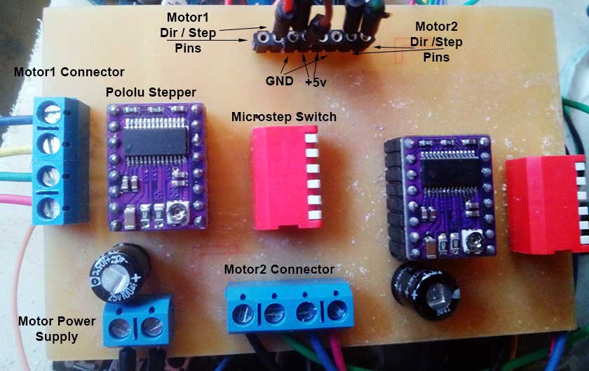
After the test of the Fabduino with the Pololu and stepper motors, the obvious part is to buil a Motor shield to rationalize the wiring, as molex screw conectors are needed, the circuit was made with through the hole technique ... a very relaxing thing after month of surface mounting welding :-). I added some microswitches to control the microstep pins of the Pololu. I think I going to design also a "control shield" that will carry the push buttons and the Lcd Display.
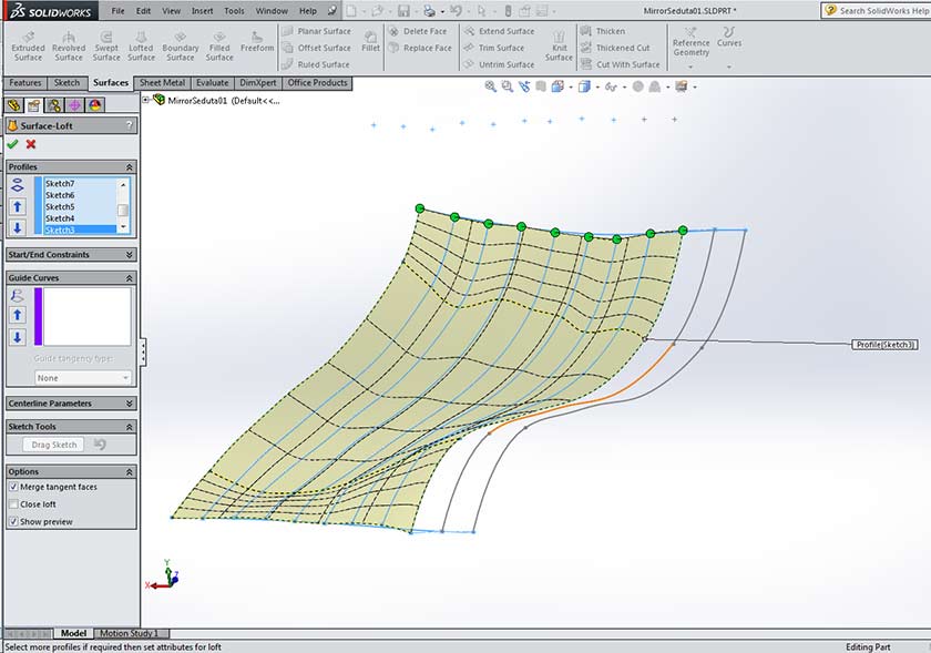
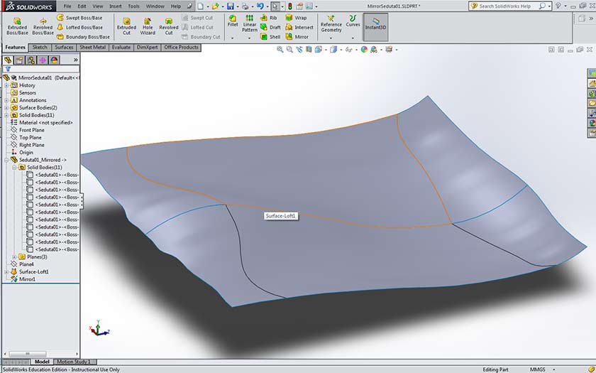
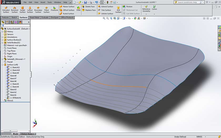
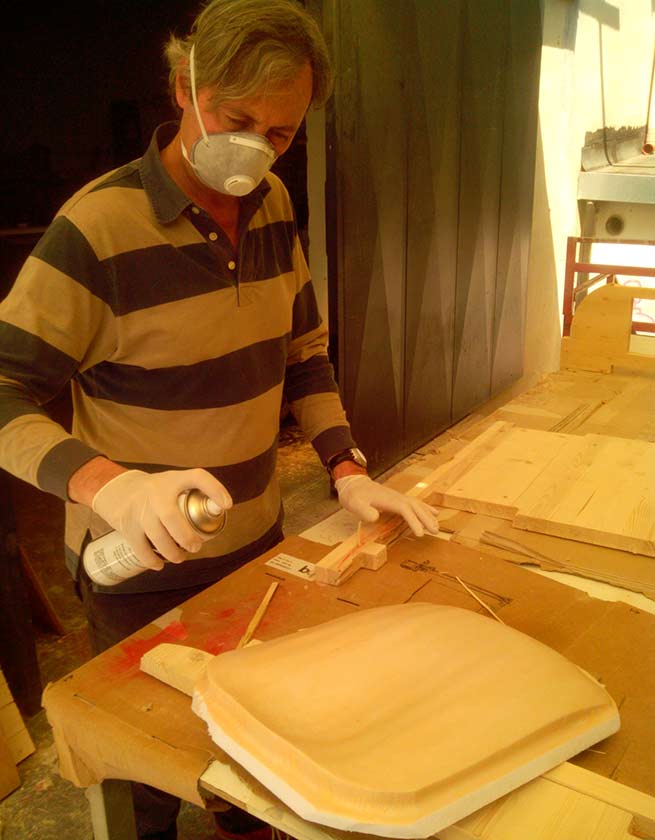
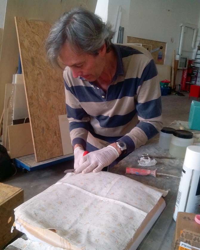
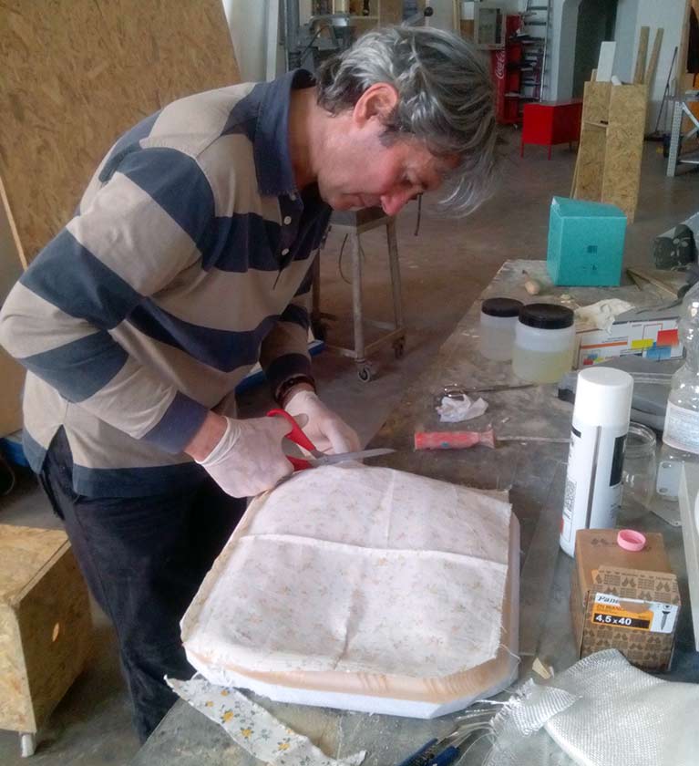
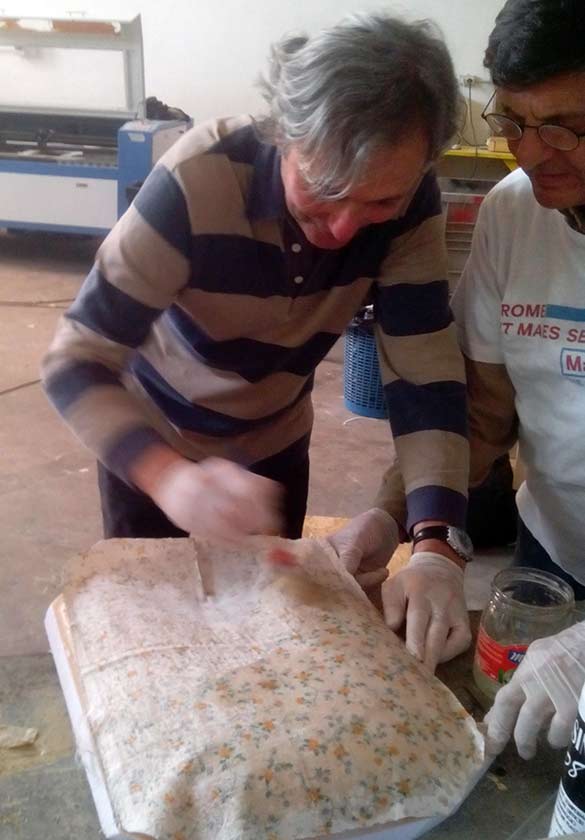
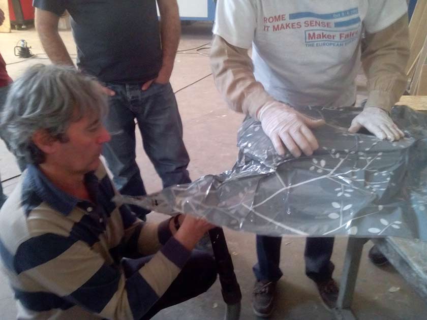
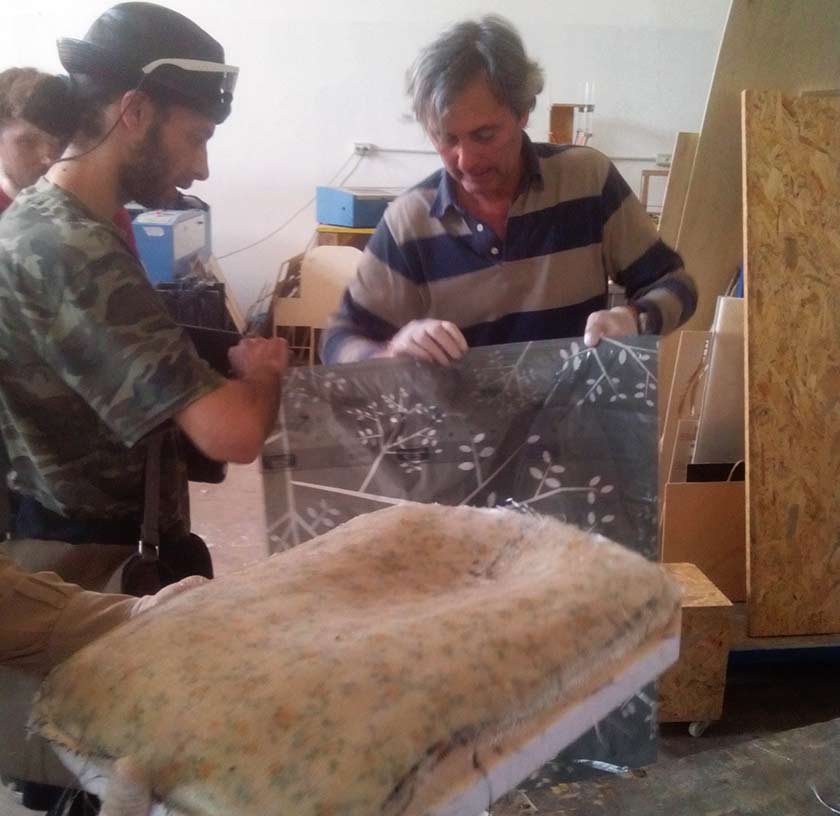
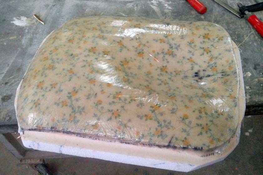
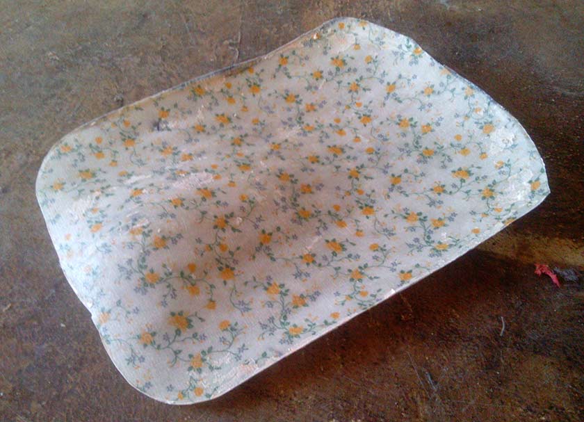
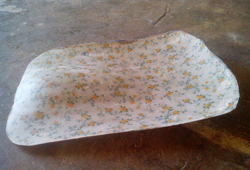
For this Assignment my goal is to design (well ... copy my friend's Marco Tonci design, and make a mold to "produce" copies of a comfortable seat for personal chairs.
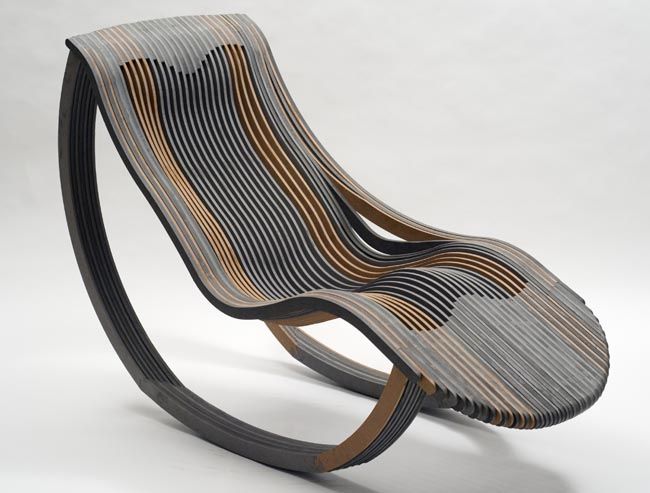
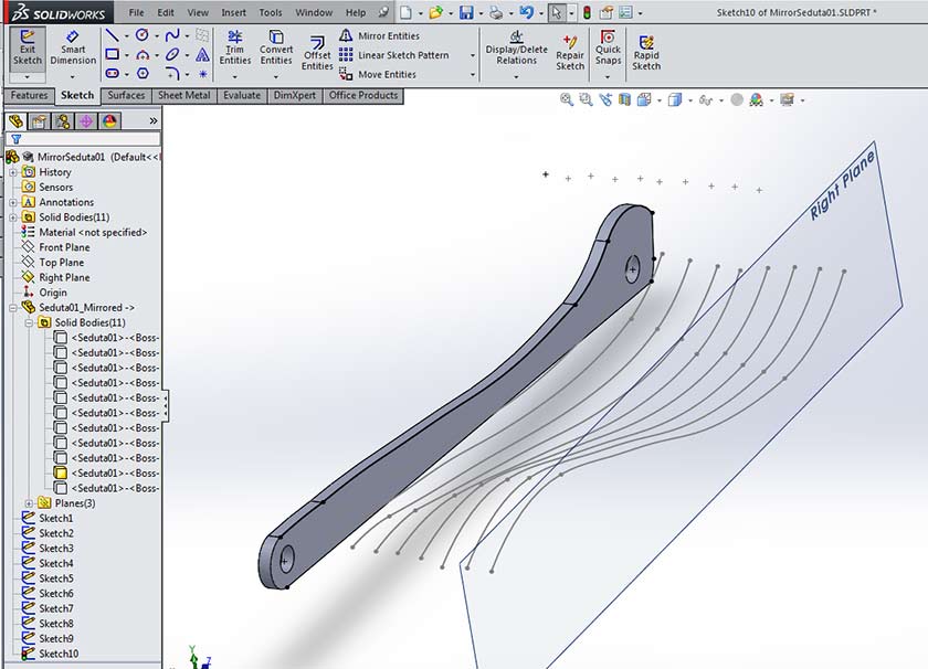
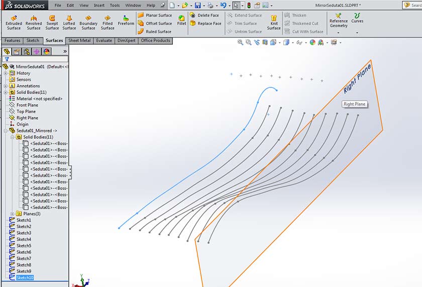
Designing the seat was a difficult task, it was my first time on surface creating. I made some trial and errors before I asked the help of Lorenzo. With Lorenzo's hints I redesigned the seat the proper way, making a unique Solidworks "Part" (not an "assembly") with all of the different profiles each on an equidistant reference plane.
Here are the files:
STL for 3D Molding
Solidworks Design File
The slow pathway .... Eagle is now very friendly, and everytime I use it, I learn new things and the work is getting faster, so I thought to redesign my Arduino Board, the Fab ISP (this time in the USB style) and obviously the hello bus boards and the hello I2C boards. The hello bus boards were easy to produce, a few components to solder, the 5 boards I milled were all working except one.
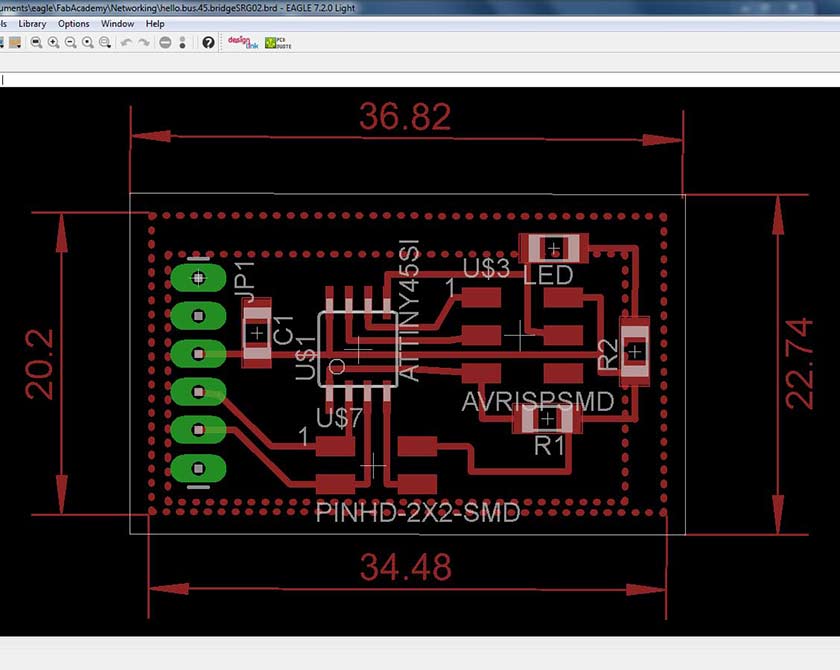
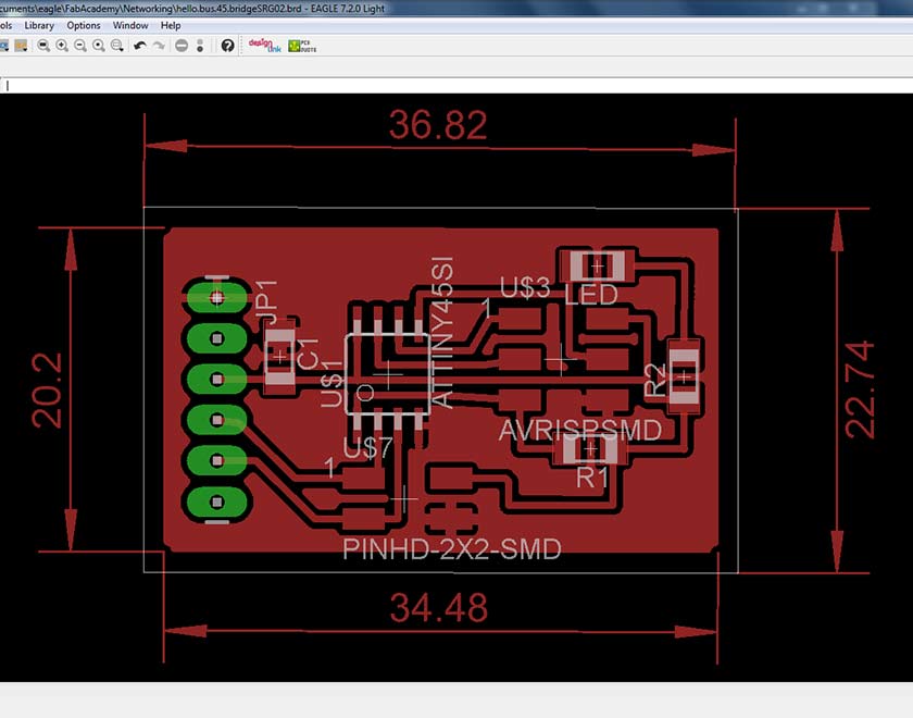
One of the things I use extensively are the poligons, the first picture show polygons I made, one for the ground plane, and the ather to fill some part where the ground Plane don't reach. In the second Picture you see the Bridge Board with Ground Plane and Copper filling results using "RATNEST" command. The result of the ratnest command is tight, but you can change the parameters if you are worried about yours soldering skills. The great advantage you have is the milling time is reduced by far or if you have a much faster fiber laser, you produce less copper residuals.
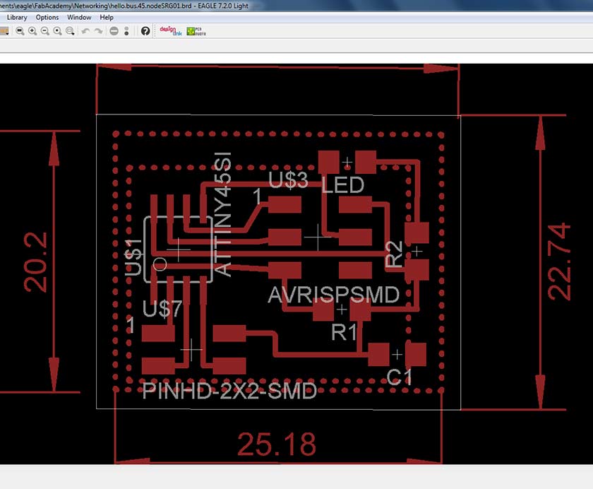
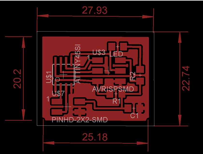
The node board with visible polygons and the node board with ground plane and copper filling
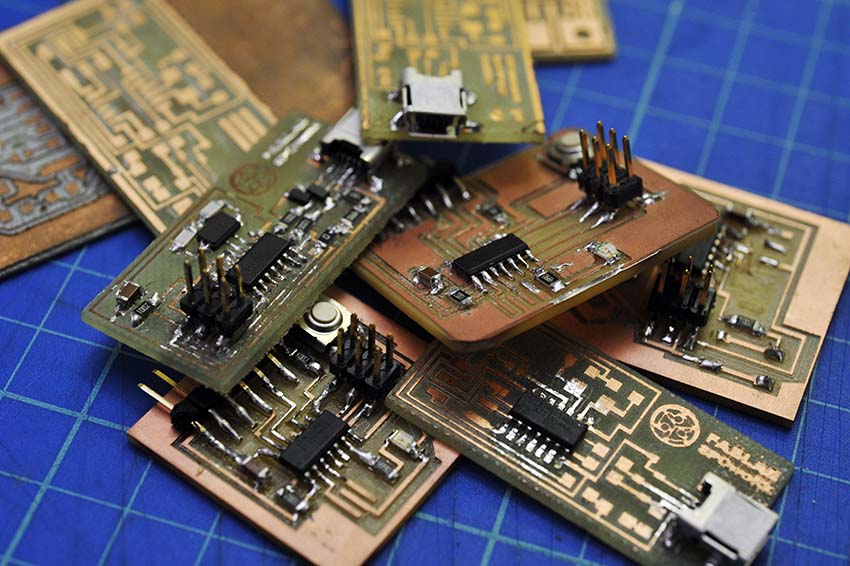
The Last step before milling the circuits is to simulate the cut with the CAM program, if you carefully check the results you can find all the errors like shorted traces and missing traces. The last picture show a fistfull of boards in one hour milling :-)
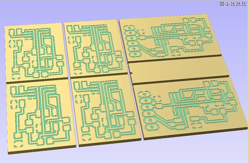
The milling results .... almost perfect circuits and then soldering the Board. Volume Production !! :-)
Initialising the boards instead was very difficult and I had to read many documents and tutorials, the sucessfull way was with Atmel Studio and the Atmel Programmer, finding the right procedure took a lot of efforts and the help of Lorenzo was necessary.
My next test will be with the Hello.I2C board, I want to learn how to connect an LCD Display with serial comunication so I just need 2 wires instead of six.
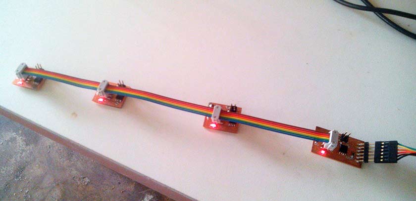
My weakest point, is programming and controlling a system via terminal/command line .... so for this assignment I choose to develop and make work the software control of the project :-) hopefully my mate Alessandro Papaleo is much more capable.The first step was to install the pygestalt and relative utilities:
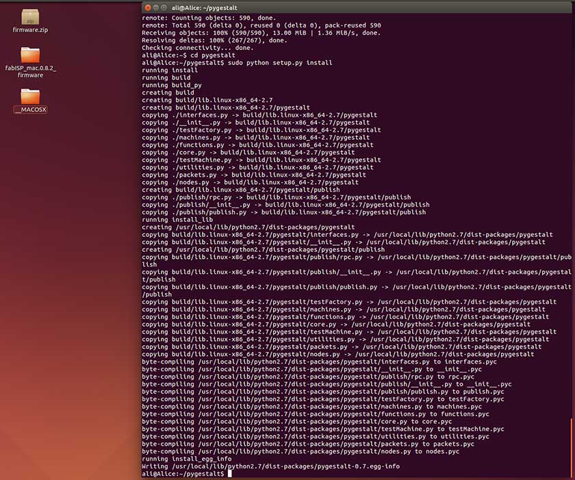
Following the Shawn's instructions. The procedure is so well documented tha even a linux newbie like me was able to succeed. The secon step was to make the Gestalt Nodes comunicate with my pc. This part was not easy and it took several hours and many try. The USB port did not comunicate with the rs485 FTDI cable so we could not reach the gestalt boards
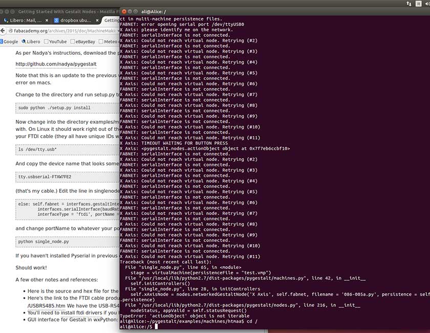
.... But then Alessandro found the solution ! ... to activate the USB serial comunication you need SUDO permissions ... et voilà :-) connection established !!

We replicated everything on Alessandro's MAC, but again no comunication ... the problem was solved changing in the pyton program the USB recognition line from: /dev/ttyUSB0 to: /dev/tty.usbserial-FTXW4FZ4 From there the path was flawlessly, just a matter of study and understanding. We tested with the single_node.py then the two nodes xy_plotter.py and then we learned how to add two more axis in the python code and how to change the code parameters. The further step was to understand how to move with our coordinates manually inserted and how to automatically read a file whit G-code coordinates.
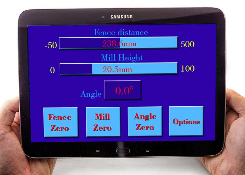
In this era of very cheap devices with touch screen I thought it could be a nice idea to build a Python App to control wirelessly my final project, the router table. A modern tablet or phone has a great graphical potential that can help build an easier to use interface.
To achieve this goal I need to program a Python App ... Well I need to learn how to program in Pyton ... and it's not an easy task for someone like me who never programmed anything, so I started two online courses: the Codecademy course and the Learn Python the Hard Way course.
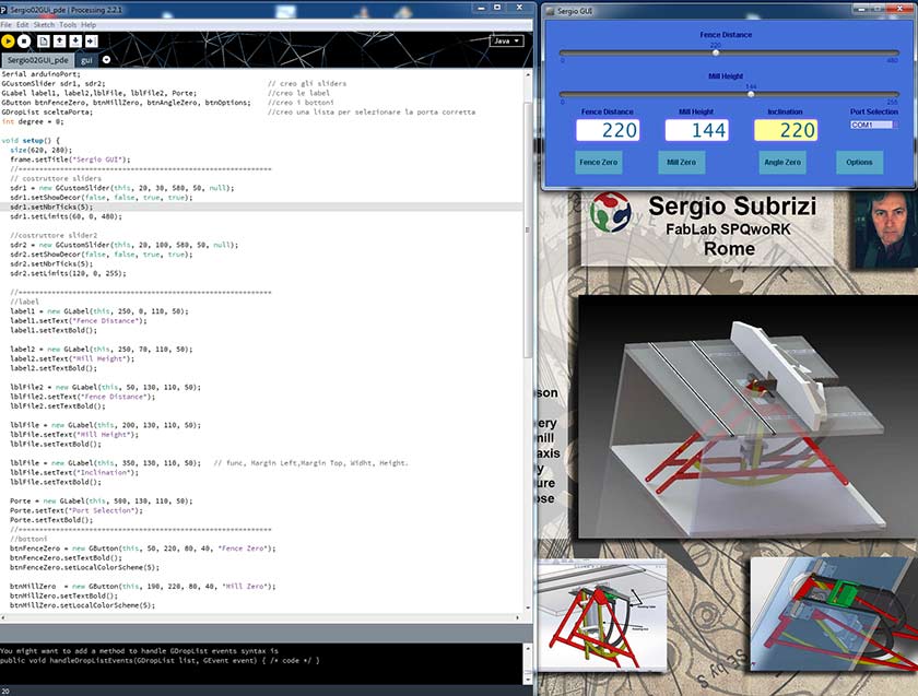
I started with Codecademy, but after a nice start I had so many problems because too many things were not explained, so I started the "Learn Python the Hard Way" which untill now is perfect for someone like me who as difficulties even with the simple terminal use. The interface will have two sliding cursors that will set the desired position of the fence or the heigt of the mill, some buttons will help the initial settings.
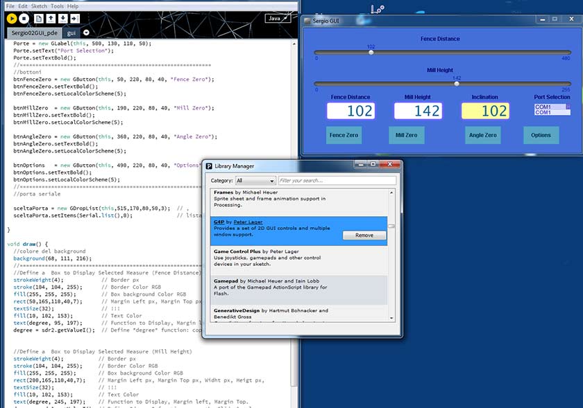
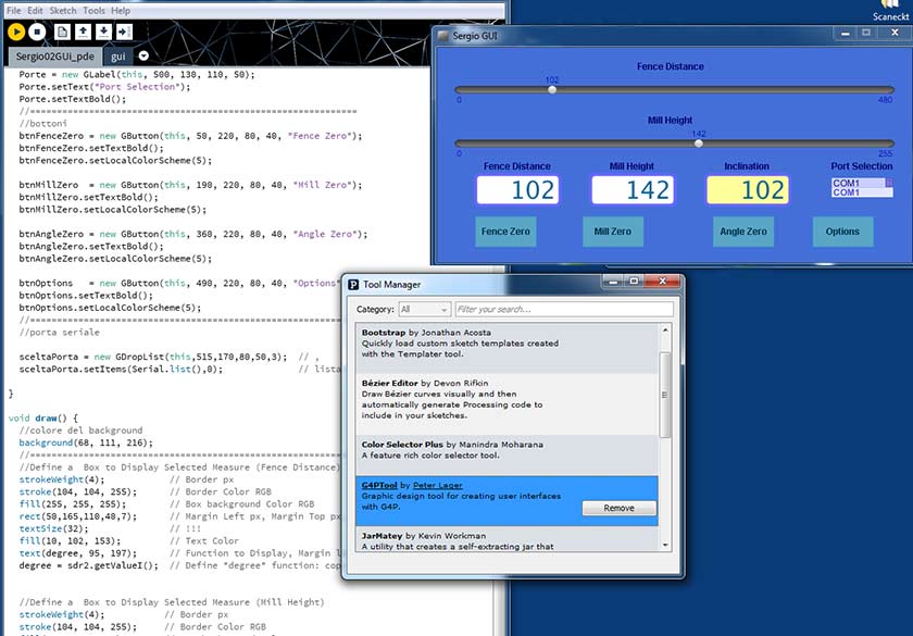
 Meanwhile I slowly progress with Python, I followed a 4 hour course on Processing and I am now able to make the desired interface with this program. The first step is to install Processing 2.2, then some tools and libraries in my case G4p library and tools are needed for the graphic design.
What will it do?
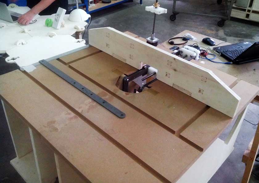
The Router Table or "mini wood shaper" is a very useful woodworking tool. One of the main functions is to "shape" the borders in a way that CNC machine can't or is very improductive doing it. Another important use is the ability to easily make many type of joints, but the list of productive working possibility is long. Many are the bits you can mount on it, from simple end mill to custom shaped cutters, to Bearing Router Cutters. Safety and precision can be implemented with many accessories, there is a big offer in the USA market for customization tool an accessory for the router table.
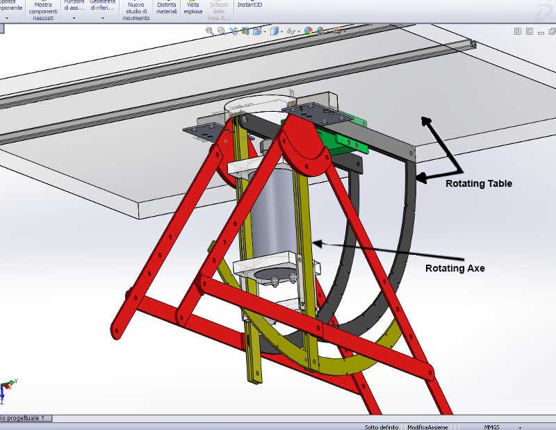
Rotala project is an evolution of the classic Router Tables. Electronic control of the fence movement and of the height of the mill will ensure better precision versatility and performance. The ability to "rotate" both the table and the router axe will offer much more versatility allowing different border shape with the same mill. The rotation for the moment will be manual with angle digitally displayied. Future customization and developement could be the automatic inclination and automatic feed of the wood piece to make a never seen CNC Strip Planking border shaper for canoes, kayak and small boats !
Who's done what beforehand?
There is not a native electronic router table on the market and not a tool with inclination capability apart the DIY projects. Some Aftermarket accesories are sold in the USA like Ready2Rout Electronic Fence Positioner (600 USD) and the Ready2Lift router height controller (630 USD) or The PowerLift is another exemple (390 USD). None of them has the inclination control.
What materials and components will be required?
The structure and mechanics will be metal made, some parts will be commissioned to a Metal Laser cutting service (quoted 80 euros for all metal part, less if only the goniometric structure is laser cutted), the others will be FabLab made with a drill press and grinder from simple metal bars locally available (quoted 20 euros). Wood (MDF or plywood) for the container structure and the table, some HDPE for the spindle holder and some Teflon for the sliders for a tatal cost of 140-160 euros.
Electronics will use self my made Fabduino, 4x20 LCD Display, 2 nema 23 stepper motors, pololu stepper drivers, an encoder, 12v power supply, the total electronic estimated cost should be in the 40-50 euros range excluded the two nema 23 motors (50 euro), water cooled electronic spindle with inverter will cost other 300 euros (it's mandatory the ER20 collets capability).
Where will they come from?
All the structure will be Km 0 available, the electronics will have the same source we used for the Fab Academy materials, (Digikey or Web source)
How much will it cost?
A total cost of 250-280 euro is estimated (with no router), 140-160 euro for the structure, 100 euro for the electronic components, the water cooled electronic spindle with inverter wil cost 290 euro.
What parts and systems will be made?
Only Pololu drivers will be bought and some part of the structure will be commisioned to a metal laser cut service, everything else will be FabLab made.
What processes will be used?
From 3D desing to metal cutting/welding ..... The project will need almost the knowlege of all the assignments of the Fab Academy.
What tasks need to be completed?
Many refinements and implementations to the software control, a complete CAD revision and check, and most important of all, a complete study to insert mechanical adjustments for fine tuning and recovering holes misalignments. Acceesories also need to be developd like dust extraction, safety protection and auto zero of the moving parts.
What questions need to be answered?
The use of the Gestalt nodes in the Mechanical Design and Machine design opened a new perspective to this project, the hardware and software implementation showed unlimited possibility apart my programming inability :-) ... for the moment :-)
What is the schedule?
To have all the electronic ready for the 10 of June and the mechanics for the 24 of June, software implementations will follow during the summer and maybe more (much).
24 June Udate Well, I was a litle optimistic, the basic mechanical and electronics feature worked, but many refinements and new parts are needed. The new schedule is to have machine completely working for the end of july which is realistic, then all the project need a complete design refinements to add building tolerance, study and document a building instruction process and a long field test. Six month it's a minumun of time to achieve this goal, this I hope will go parallel with a Kickstart campaign.
For all the future development follow: The Rotala Project Blog
How will it be evaluated?
The goal is to have a performing semi-professional woodworking tool. The working capabilities, performance and working safety conditions will be the parameters.
This project is born for necessity. Most of my work with the CNC router needs to be refined and some works can't be totally made with the CNC. When it comes to make tenons, some joints and in general all the border works, the CNC router is not the best option. Rotala is the answer to some of my needs. I already built a very basic router table but the manual setup of the parameters is time consumig, internet is full of nice manual DIY projects, but almost all cannot solve completely my needs. For Years I took part to woodworking forum, and there is a good interest to DIY woodworking projects, so my "dissemination" plans will start there: the woodworking forums around the world :-). Fab Academy's site is a dissemination place too, and I think to launch also a crowfounding campaign. The idea for this project is to release it as Creative Commons CC BY-SA ( Attribution, Share Alike) and distrubute all the information to help built it in a dedicated blog. As some parts could be difficult to made outside a FabLab comunity, I plan to make some kits of the most complicated parts and reinvest the income in upgrading and developing this project ( as Fiore Basile said, a good project is never finished :-) and some other I have in mind .... like a metal bender, a bit sharpner have a look at my Pins on metalworking ... or some woodworking tools like a portable sawmill, a thikness sander .... oh, but those are just old ideas when I did not knew "how to build almost everything" :-)
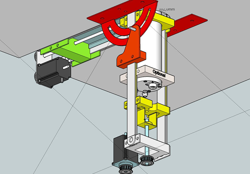
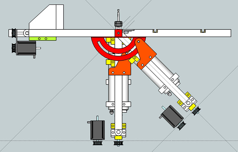
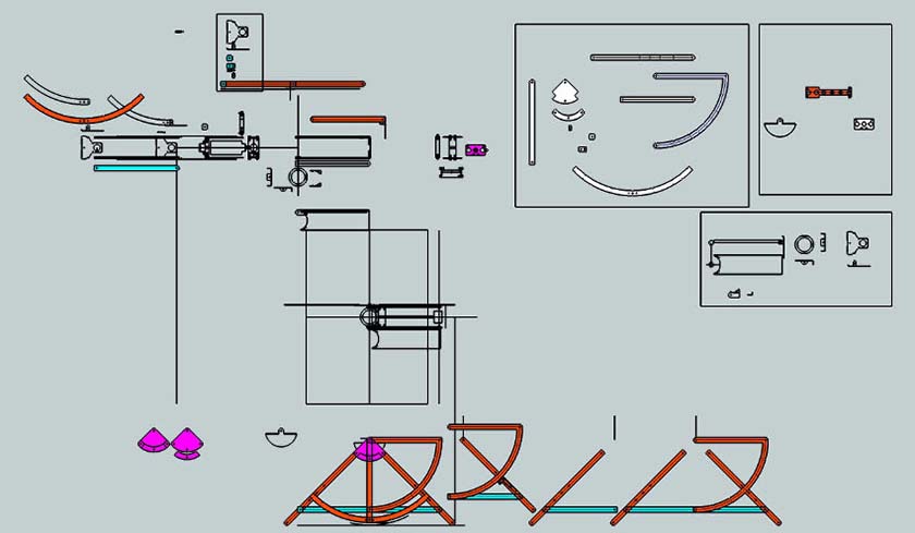
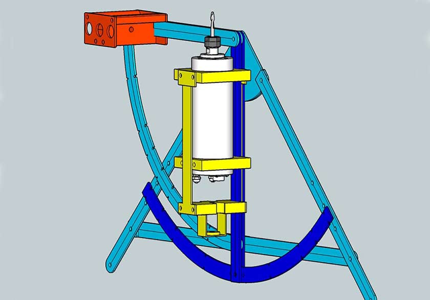
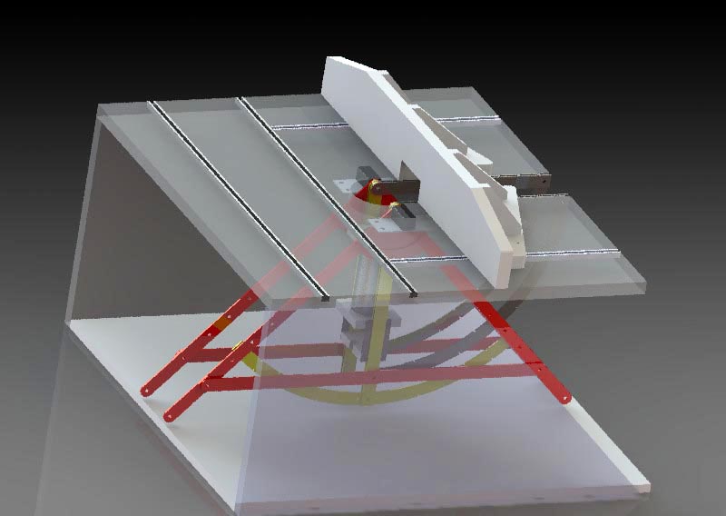
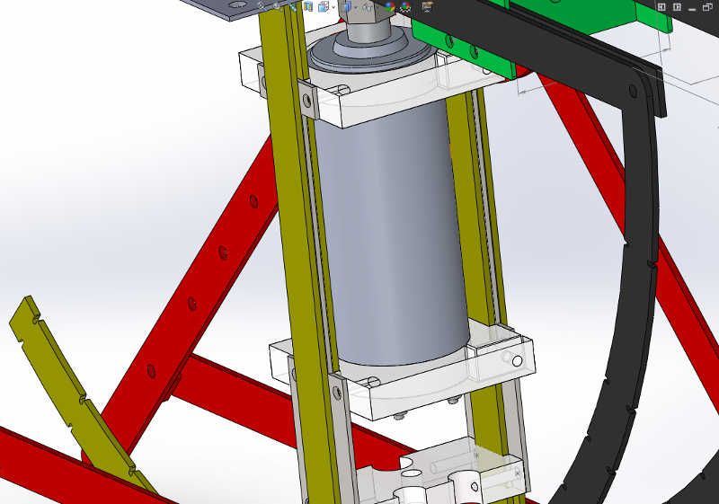
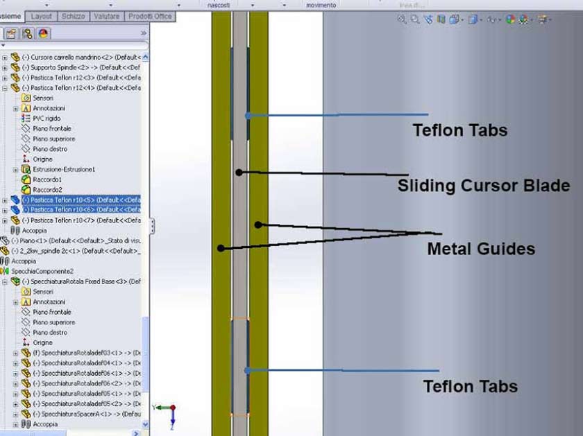
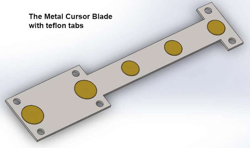
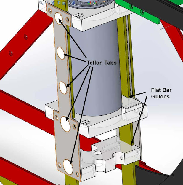
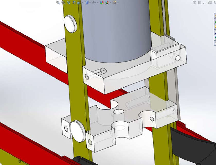
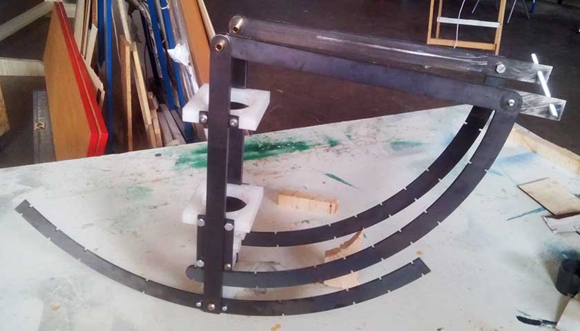
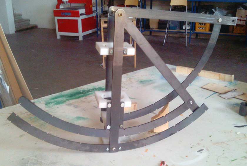
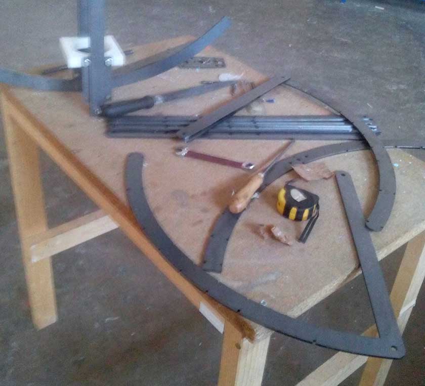
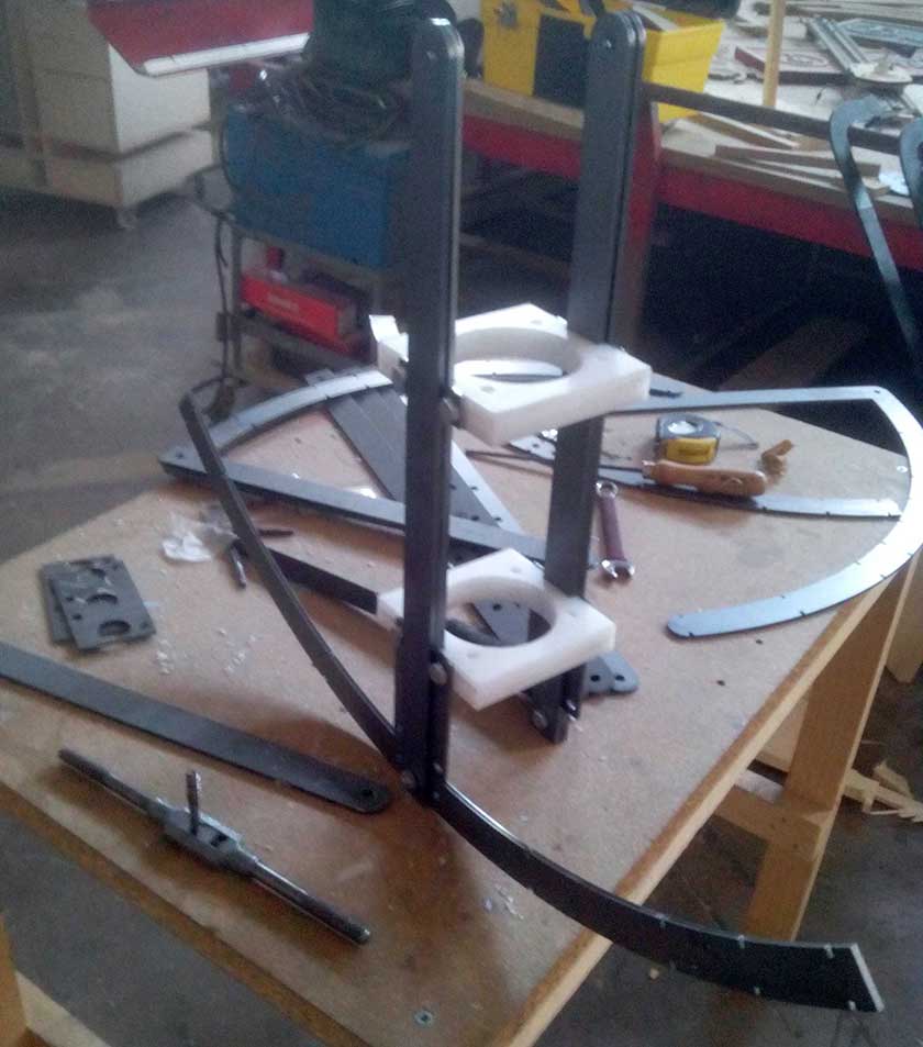
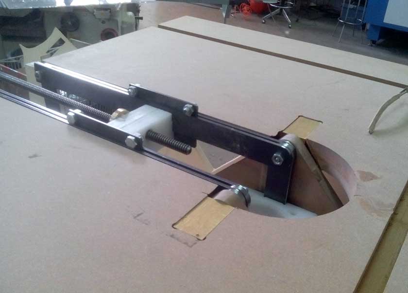
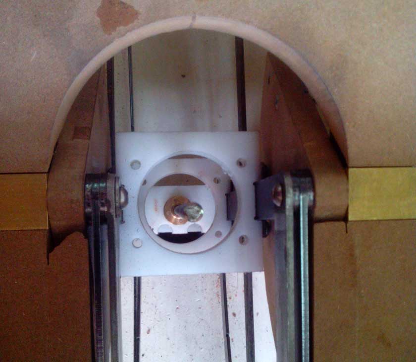
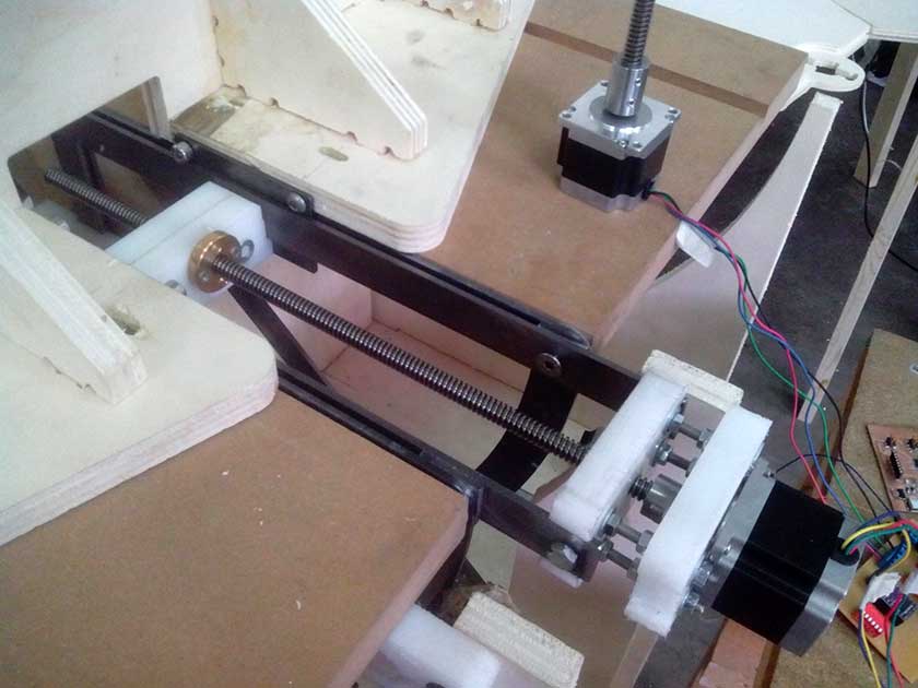
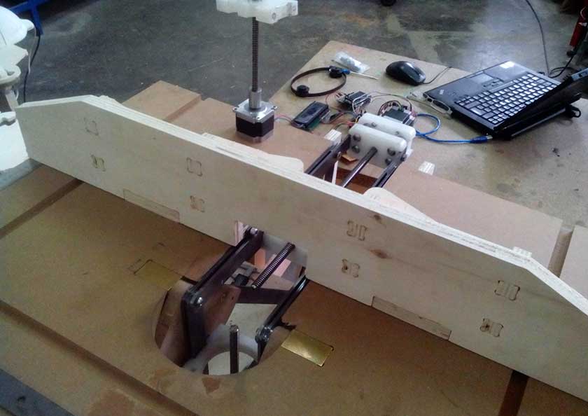
I started with some idea one of them was this first-photo: but my friend Marco Tonci inventor and designer had a better solutions, he drew with 2D CAD an innovative full metal structure for my router table, to better understand it I need a 3D sketch so I imported the 2D CAD in Sketchup. The pieces need to be cut by a metal laser cut sevice ... but I am thinking to mill them with my CNC in aluminium instead (or carbon fiber if not too expensive).This is the idea of the height movement: The idea is to have a "sandwitch" of a 4mm metal blade (yellow) sliding inside other 2 4mm metal blades, HDPE or Teflon "skates" will be used. In this picture I colored the part with four colors (third photo), the parts that rotete are in blue, yellow is for parts that move in Z axis and orange for the Fence support (X axis), Turquoise is structure parts that don't move.

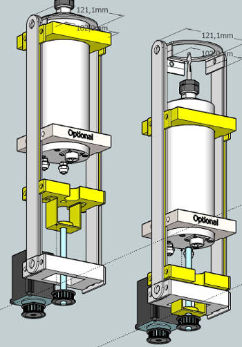
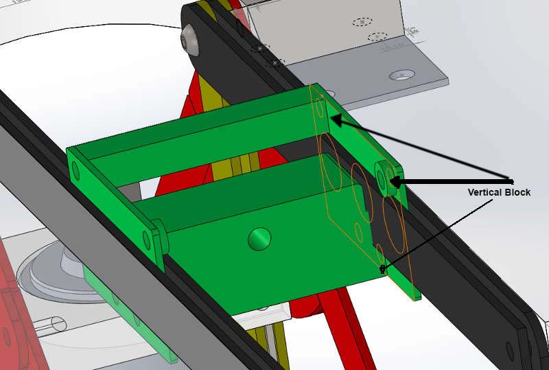
Designing in Solidworks it's becaming a pleasure. Here we see some features of the project. The basic idea is to use material frequently available. Some parts would benefits if laser cutted, metal laser cutting service is not difficult to find and generally economic. The idea of the sliding mechanism is to be economic without sacrificing precision. The system consist in two 4mm metal blades and a 3mm cursor wich slide in between, some 4mm teflon (or any other suitable material) tablets are inserted in the cursors to achieve a better sliding. Same for the Fence movement, the carriage slides between the metal blades, vertically is held in position by blocks, and laterraly by the blades with teflon tablets