Building the site is the primary goal.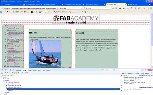 Thank to Lorenzo, I made an online course with CodeCademy and in a few days I knew the html/css principles which I found very easy and amusing.The structure is composed by Three pages: the first one is the home page where you get the basic informations and the link to the other two pages.
The second page is about me, what I did and what I do now. The third (this one) will have all the work, the documentations and the exercises.
Divide the page the way I want was a bit tricky ... Margins, Borders, Paddings, Contents and their relative properties when they interact with other elements, is at the very beginning difficult,until you remember all the command.
Thank to Lorenzo, I made an online course with CodeCademy and in a few days I knew the html/css principles which I found very easy and amusing.The structure is composed by Three pages: the first one is the home page where you get the basic informations and the link to the other two pages.
The second page is about me, what I did and what I do now. The third (this one) will have all the work, the documentations and the exercises.
Divide the page the way I want was a bit tricky ... Margins, Borders, Paddings, Contents and their relative properties when they interact with other elements, is at the very beginning difficult,until you remember all the command.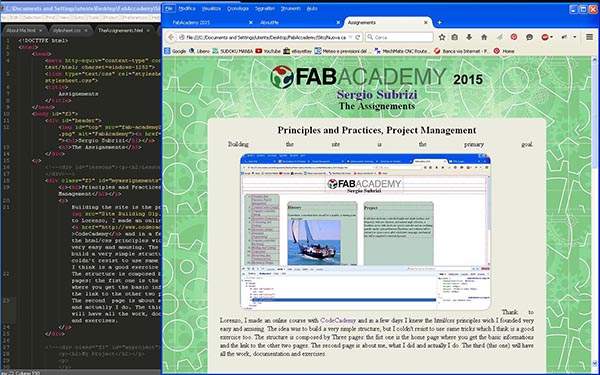 The code was written in a text-editor program called "Sublime Text", It has some usefull things like line index, color code highlights. And "firebug" is an helpful extension to my browser. I like a "minimalistic style" site ... well mine is not the case :-), I choosed to test and play with various commands and tricks as part of the exercise and those are the results. This was one of the assignments I was scared of ... never used html/css and I am an absolute beginner in programming. I think there are still many things to learn, but I am not scared anymore :-).
09 Feb update
Some other progress in html: in my project development I choosed to divide in three argument, Mechanical, Electronic and Programming. the html/css is now adaptive and seem to works right :-)
2 mar update
Some restiling of the Html/CSS, I optimized the page for a 1024 resolution, the images are a little bit bigger
16 mar update
Ok, time to chage completely the structure of this page. I like my "first" site, I've learned a lot, I tested some nice tricks, but I need something different to better document my assignments, looking at other's students work I understood how I can produce a much better documentation and work. For the site, I liked what my mate Tommaso did with picture gallery in his site. I think more and bigger picture can help the documentation. Instead of rebuild all my site I choosed to change just the assignments page, so my site would not be totaly upset, but will mantain his original aspect.
We started this assignment with the programs used in the graphic field: Gimp and Inkscape. The latter was a very nice surprise, I used Adobe Illustrator time to time, his interfase is quiet familiar to me, I have a 25 years professional experience on using Photoshop ... Lorenzo gave me some hints to start and after a few hours I had no problem to navigate the menus and using it the same level I used to do with Illustrator. Gimp was a different story, it took me much more time just to be able to do very basic operation, my firt exigence was to have the mouse scrool-wheel set to work as zoom-in and out, finding how to configure the funcion was a nightmare, everithig can be custumized, but at the price of simplicity. Also command like "canavas dimension" "save as" "resize level" are difficult to understand ... to save in the most common format (jpg) you have to use "export", "resize level" is not as easy as photoshop ... but you know ... Gimp vs Photoshop is like using my left feet instead of my right hand .-).
With some headhache and time now I am able to do most of the basic operations and photo retouching.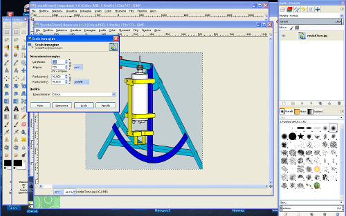 There is one thing I did not find in Gimp wich was one of my most used tools in photoshop the "history brush", I am sure I will use Inkscape as my first vectorial program, I will also use Gimp for all the pictures for the assignments but if in a rush ... it will be a second best.
As CAD I started testing Openscad, I generally need to open different files and Openscad can't, his use is oriented to designer who start from scratch and has already a good knowledge of what he need ... generally not my case :-), but could help to learn to organize my mind. Thinkercad ... well after some login problem, I discovered Windows xp it's not supported.
22 feb progress
The smaller pictures are about the move from Sketchup to Solidworks
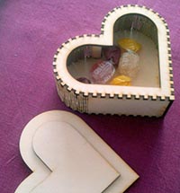
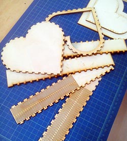
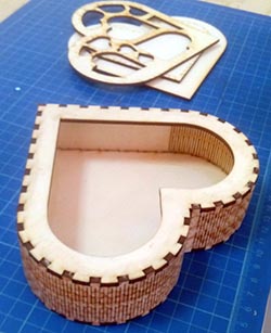
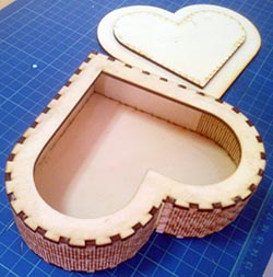
Go parametric !!! I started this week assignment with a tough thing to design: a heart-box with press-fit joint and kerf bending. My software learning curve is very slow :-( so I started with a program I know well:Vectric Aspire and I get the job done!
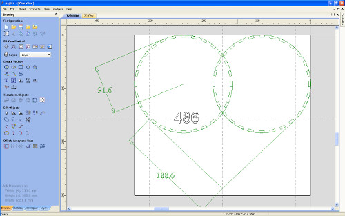
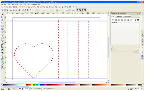
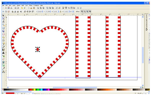
Then I thought that this kind of work need to be controlled parametrically to easy change dimensions without doing a totally new design. I think Inkscape with the clone tool could do it, my plans is to learn how to do similar things also with Antimony and Solidworks, but as I said .... my learnig curve is slow.
Although I'm still in "beta testing" phase, the cloning procedure worked well. I'am able to do fine adjustment without starting a new design, the result is quite good but better settings are needed. I choosed to have a different size for male/female joint, this is a nice feature, but much more complicated to tune with Inkscape (at least with my knowledge level). The kerf bending is nice and create no problems it's easy to design. The press-fit joint precision of the curved part is a bit different from the straight parts of the heart, I have to think who is responsible of the problem and how to solve it.
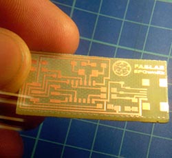
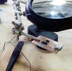
Years ago my experience on welding circuit "was" huge .... but time has passed by: surface mounting and micro components, such a different game ... the circus of "jumping fleas" :-). Anyway the biggest problem encountered was eye's "seniority" ... two pairs of glasses and lens magnifier :-).
The circuit was milled with a no brand cinese mill that I converted to work with Mach3. The precision needed was much higher than I thought, the difference of 0.01 mm was needed to have a beautiful result with the 20° 0.2mm engraving v-bit (the 1/64 end-mill was not arived still. I used an 30mm MDF board as support without surfacing it (which would have been a better thing). The procedure to mill the circuit was "adapted" to my experience. FabModules has no drivers for our machines (all controlled by Mach3), so no PNGs ... I need a vector file !! With Inkscape I converted the PNG in vector with: Path/Trace Bitmap, exported in DXF and loaded in the Vectric Aspire CAM and with the pocket toolpath we had a g-code for Mach3 which worked very well.
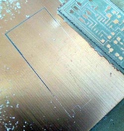
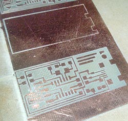
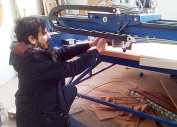
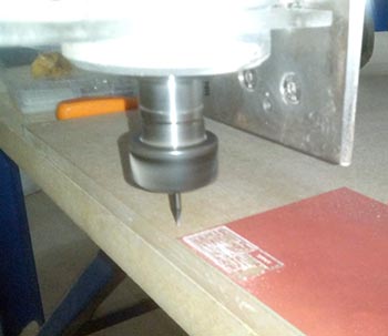
The Gentle Giant Our small mill gave some electronic problem due to interference on the PC signal ... the result was a crazy Z axis which bumped to the base, broke the bit and the collet holder was damaged ... Antonio was still missing his board ... so we tried to use our 3x2 meters CNC router with the 2.2 kw spindle :-).This time we used the 1/64 inch end-mill I was so scared to broke that costly litle bit, but the job was perfectly done at first try. I used a conservative 100mm/min feed rate and 80mm/min plunge rate. I think that I can not hide my boredom anymore if someone is going to talk about precision of my big MechMate.... :-)( p.s. the 3d Italy's board done with 1/64 end-mill bit and mine, milled with the small machine and v-bit)

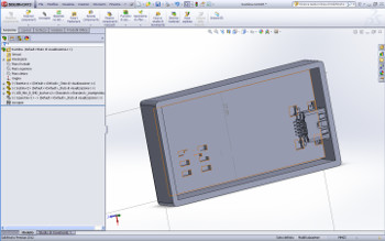
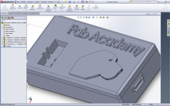
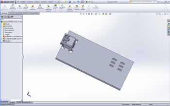
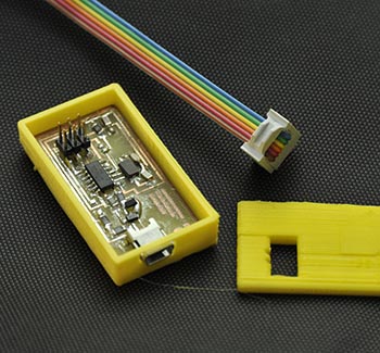
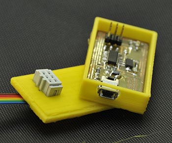
The Little Box During those days I made some progress with Solidworks, I love this program ! I wanted to test how precice is the 3D printing so I designed the box tight to my board, I also used the dxf of the board to see the placement of the mini USB conector and the Mole conector, I downloaded from the supplier site the 3D models of those conectors, and used them to have a precise idea of the dimensions. The parametric nature of Solidworks once you have a minimum of familiarity is fantastic, I was able to change some wrong dimensions in a flash. I exported the box in .stl and opened in Cura. The first try with a prusa i3 was an insuccess, I did not heat the base and the box detached from the base. The second try was not perfect but succeed (yellow box in pictures), the box was a bit larger so was the USB hole, the logo on the top quite cancelled ( I decided to scale it up a bit then ). The third try was made on a Wasp Delta printer. The result was nearly perfet ( just a little smaller that designed )
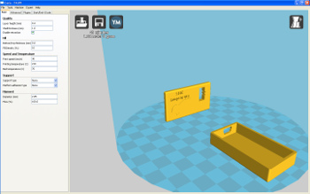
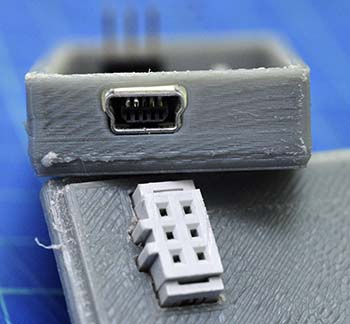
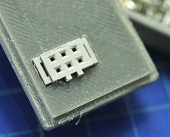
the final box ( gray ), the conector and mini usb perfecly fit !

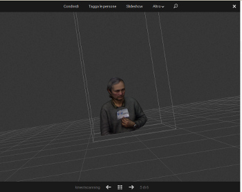
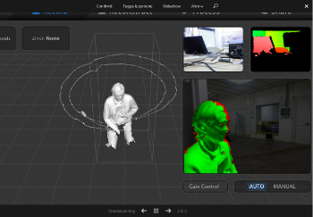
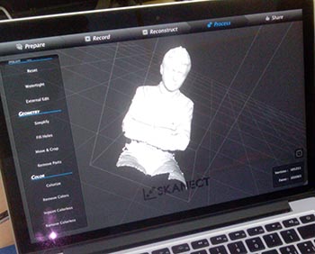
3D Scanning The first test was with Kinect and Scanekt


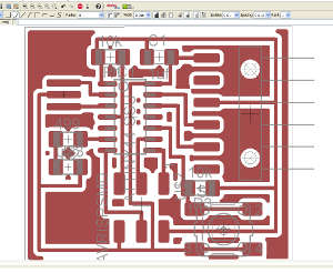
Following Fab Academy Eagle tutorial it was easy to begin circuit design, but my result did not satisfy me for two reasons: the first was the look of the circuit, such a simple style :-) the second is that the simple style is also milling time (and end-mill bit) consuming, you have to remove much more material. Eagle has a very simple command: ratsnest ! it creates a ground plane design which gives better reliability, and in the same way you can "fill" with copper other areas. This is my procedure:
Step one: Start with a board where you have routed all the signals except ground. Choose "Polygon" tool, be sure you selected the correct layer in the Parameter toolbar than set "width" and "Isolate" values.
This is the recommendation from Eagle's help menu:
"You should avoid using very small values for the width of a polygon, because this can cause extremely large amounts of data when processing a drawing with the CAM Processor.The polygon width should always be larger than the hardware resolution of the output device. For example when using a Gerber photoplotter with a typical resolution of 1 mil, the polygon width should not be smaller than, say, 6 mil. Typically you should keep the polygon width in the same range as your other wires"
I chosed 0.4mm.
Isolate value determines the distance between the polygon area and the other signals on the same layer. Make sure this is larger than the minimum trace your mill bit is capable. In this example, I chose 16 mils.
To mill the circuits, our small mill was hurted and the spindle axis was damaged ... so we tested the other router mill we had ready ... "the Mechmate" 3x2 meters CNC Router with it's 2.2Kw inverter motor ... a real giant ! well it worked as a very "Gentle" giant all of our pcb board were very well milled and no broken 1/64 end-mill !
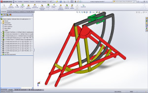
 but my friend Marco Tonci inventor and designer had a better solutions, he drew with 2D CAD an innovative full metal structure for my router table, to better understand it I need a 3D sketch so I imported the 2D CAD in Sketchup.
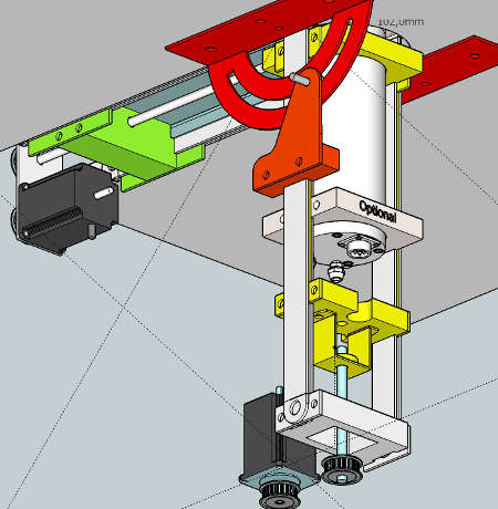
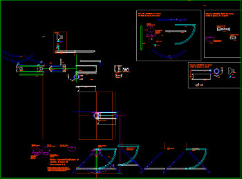 The pieces need to be cut by a metal laser cut sevice ... but I am thinking to mill them with my CNC in aluminium instead (or carbon fiber if not too expensive).This is the idea of the height movement:
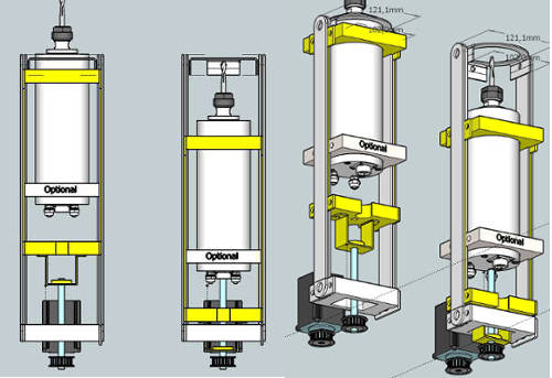 . The idea is to have a "sandwitch" of a 4mm metal blade (yellow) sliding inside other 2 4mm metal blades, HDPE or Teflon "skates" will be used.
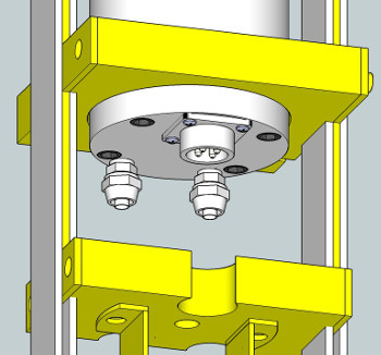 In this picture I colored the part with four colors, the parts that rotete are in blue, yellow is for parts that move in Z axis and orange for the Fence support (X axis),
 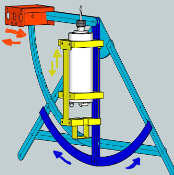 Turquoise is structure parts that don't move.
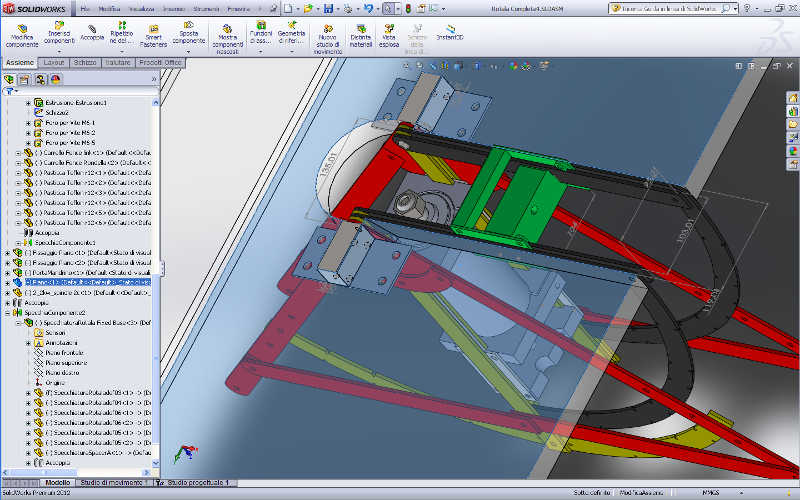
Designing in Solidwork it's becaming a plesure. Here we see some features of the project. The basic idea is to use material frequently available. Some parts would benefits if laser cutted, metal laser cutting service is not difficult to find and generally economic.

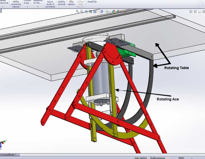
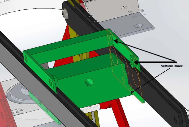
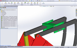
The idea of the sliding mechanism is to be economic without sacrificing precision. The system consist in two 4mm metal blades and a 3mm cursor wich slide in between, some 4mm teflon (or any other suitable material) tablets are inserted in the cursors to achieve a better sliding.
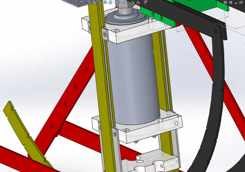
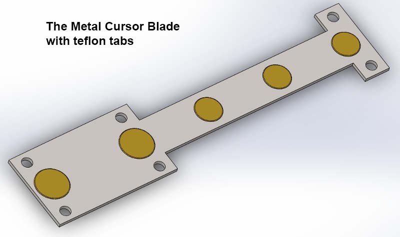
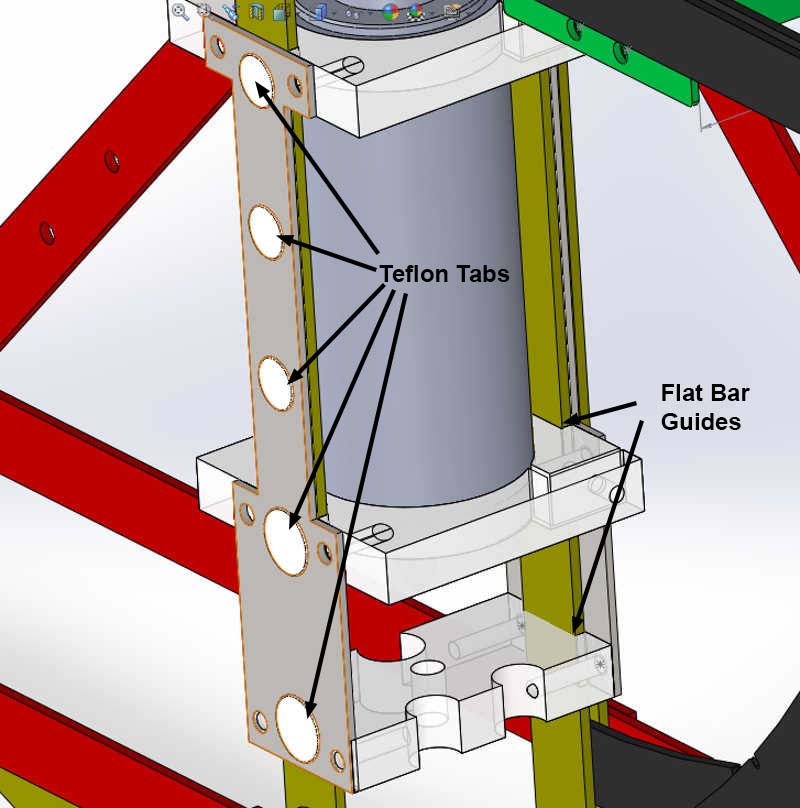
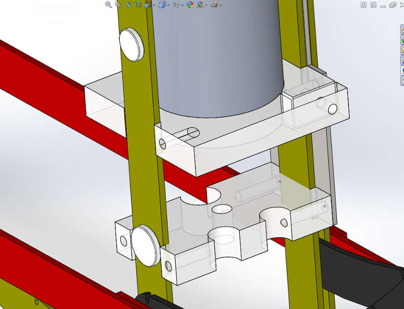

Same for the Fence movement, the carriage slides between the metal blades, vertically is held in position by blocks, and laterraly by the blades with teflon tablets