
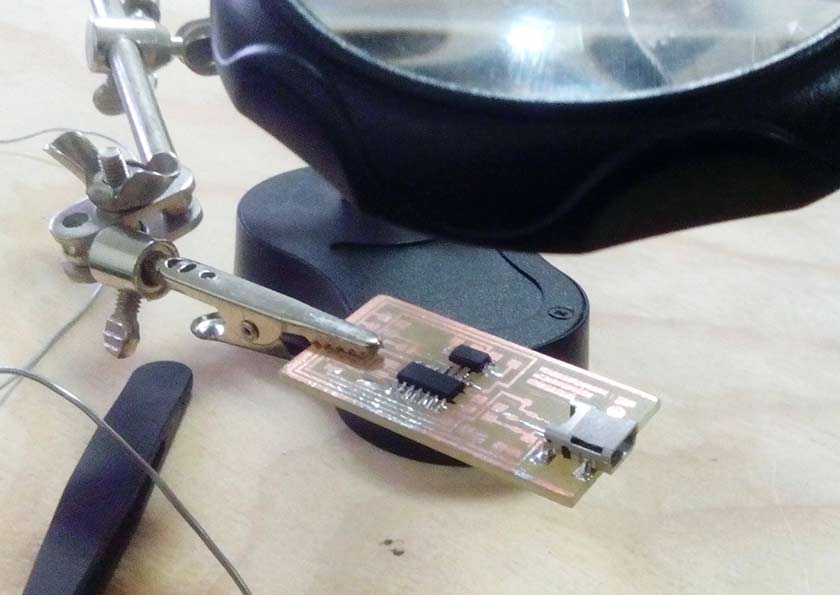
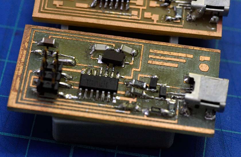
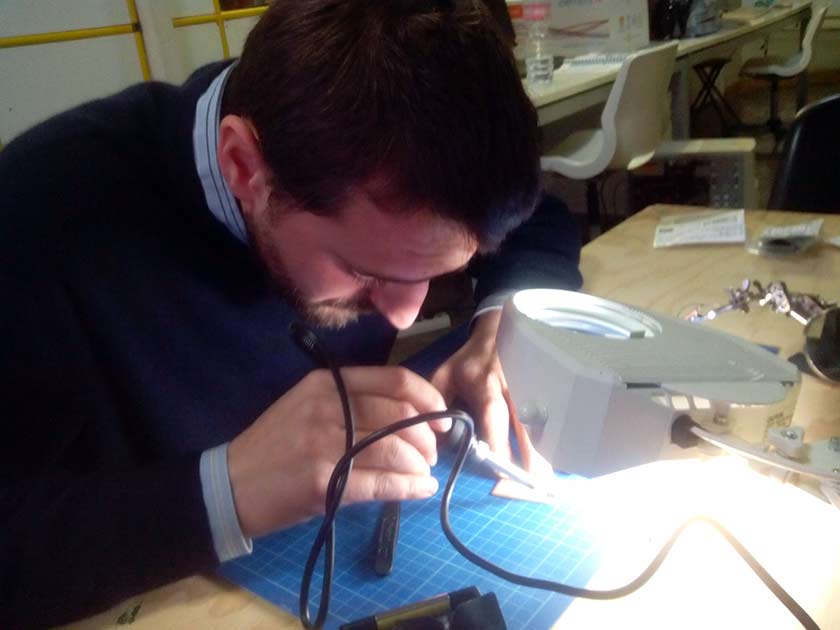
Years ago my experience on welding circuit "was" huge .... but time has passed by: surface mounting and micro components, a such a different game ... the circus of "jumping fleas" (diodes) :-) To work without problems at lest three hands are needed, one for the iron, one for the tin and another to hold the componets in place. Anyway the biggest problem encountered was eye's "seniority" ... two pairs of glasses and lens magnifier :-).
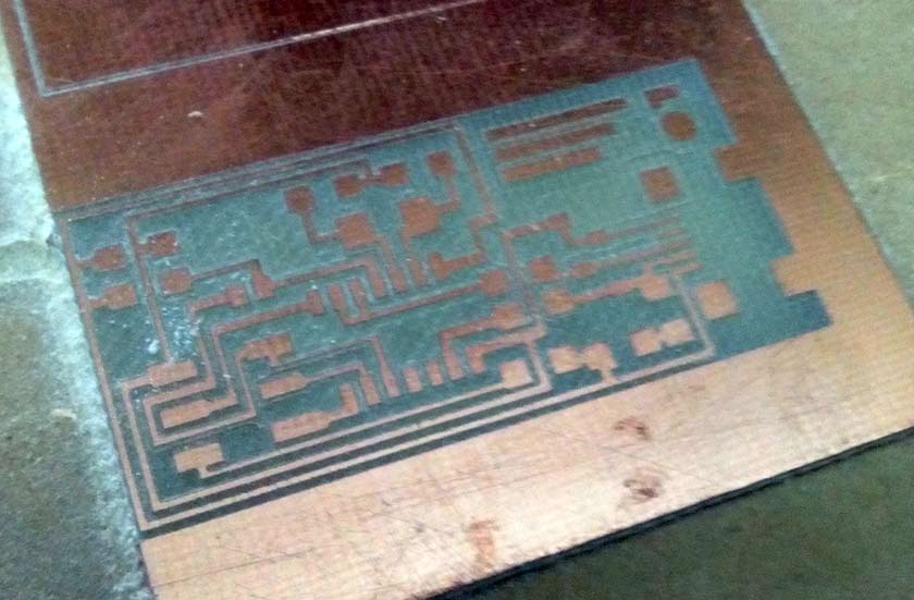
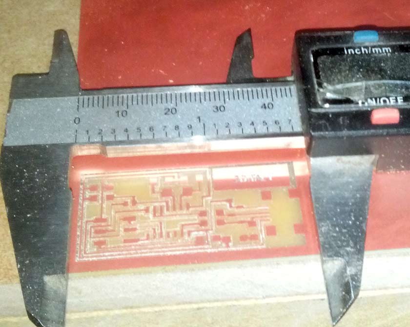
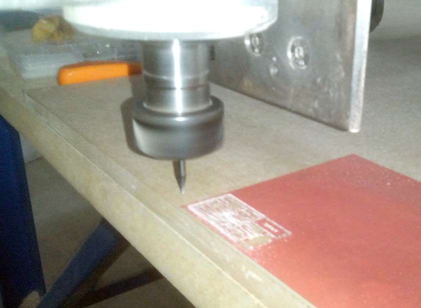
The circuit was milled with a no brand cinese mill that I converted to work with Mach3. The precision needed was much higher than I thought, the difference of 0.01 mm was needed to have a beautiful result with the 20° 0.2mm engraving v-bit (the 1/64 end-mill was not arived still. I used an 30mm MDF board as support without surfacing it (which would have been a better thing). The procedure to mill the circuit was "adapted" to my experience. FabModules has no drivers for our machines (all controlled by Mach3), so no PNGs ... I need a vector file !! With Inkscape I converted the PNG in vector with: Path/Trace Bitmap, exported in DXF and loaded in the Vectric Aspire CAM and with the pocket toolpath we had a g-code for Mach3 which worked very well.
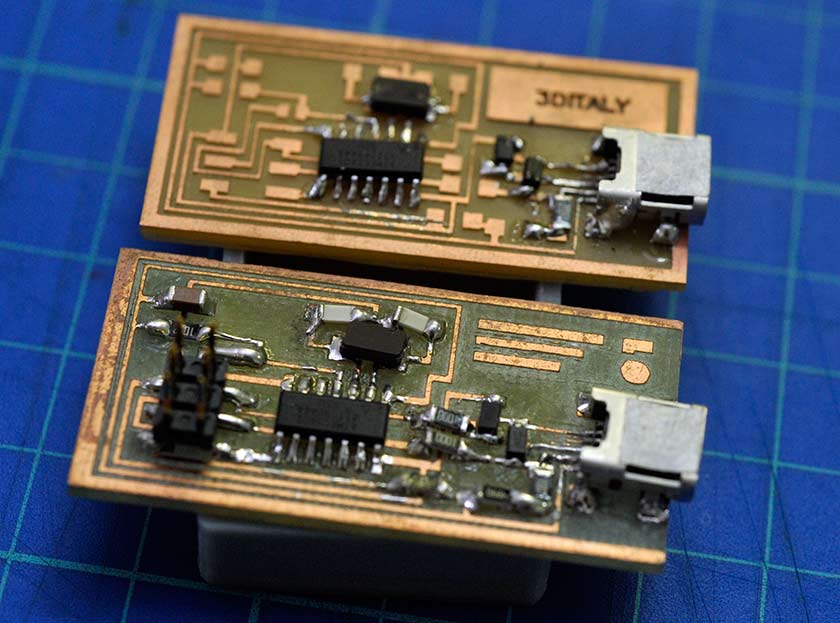
It took almost half a day to solder the small board, it did pass the smoke test, but Didn't work. After a carefull inspection meanwhile another circuit was milled I found a small diode was inverted. The soldering process of the second board was quicker (experience :-) ) some trouble on installing the correct drivers, but this time it worked perfecly ! I managed also, with a little damage to the board, to unsolder a resolder the diode and ... yesss !!! also the first board worked well !
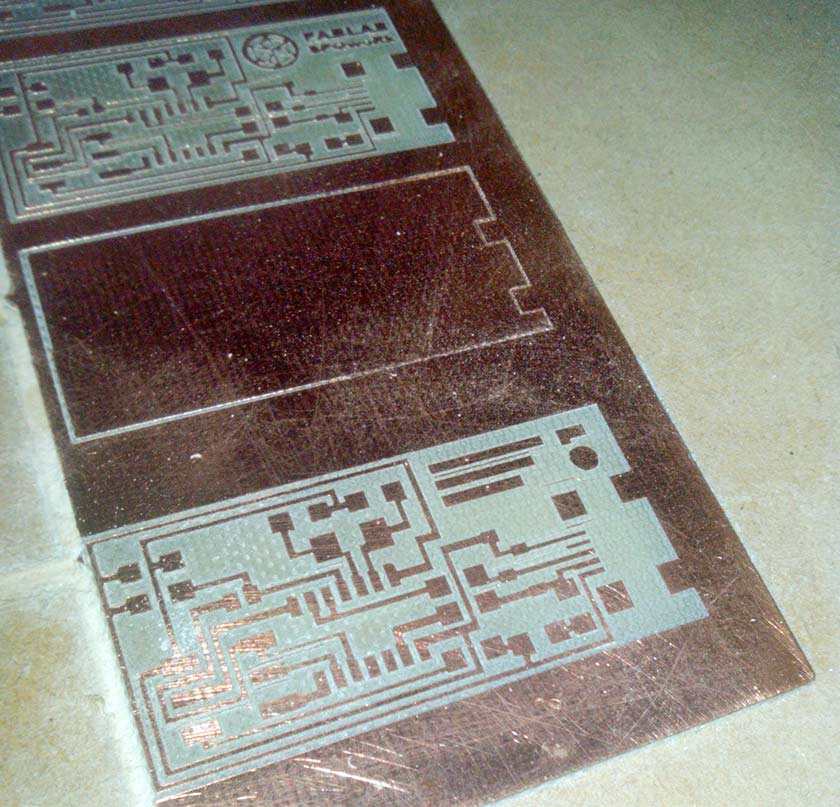
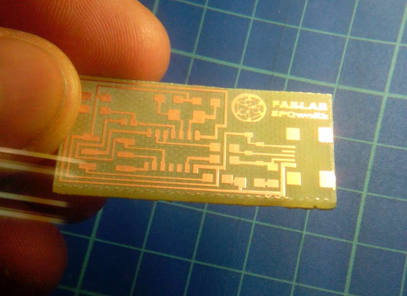
The Gentle Giant Our small mill gave some electronic problem due to interference on the PC signal ... the result was a crazy Z axis which bumped to the base, broke the bit and the collet holder was damaged ... Antonio was still missing his board ... so we tried to use our 3x2 meters CNC router with the 2.2 kw spindle :-).This time we used the 1/64 inch end-mill I was so scared to broke the costly litle bit, but the job was perfectly done at first try. I used a conservative 100mm/min feed rate and 80mm/min plunge rate. I think I cannnot hide my boredom anymore if someone is going to ask about precision of my big MechMate.... :-)( p.s. the 3d Italy's board done with 1/64 end-mill bit and mine, milled with the small machine and v-bit)
Initializimg the FabISP:
The Atmel MkII programmer was the device we used to "bootload" the FabISP in-circuit programmer, The software used was Atmel Studio.In "Device Programming" I checked the "Target Voltage" Read (5.1V) , then "Device Signature" Read, then switched to "Memories" tab then I navigated to the firmware folder and selected the ".hex" file and hit the 'Program' button. The "verified" message confirmed that the device was properly programmed.