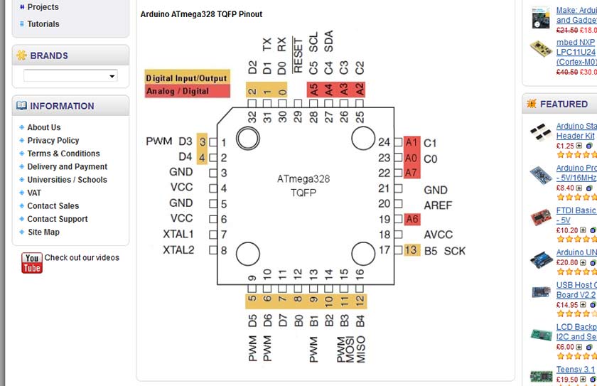
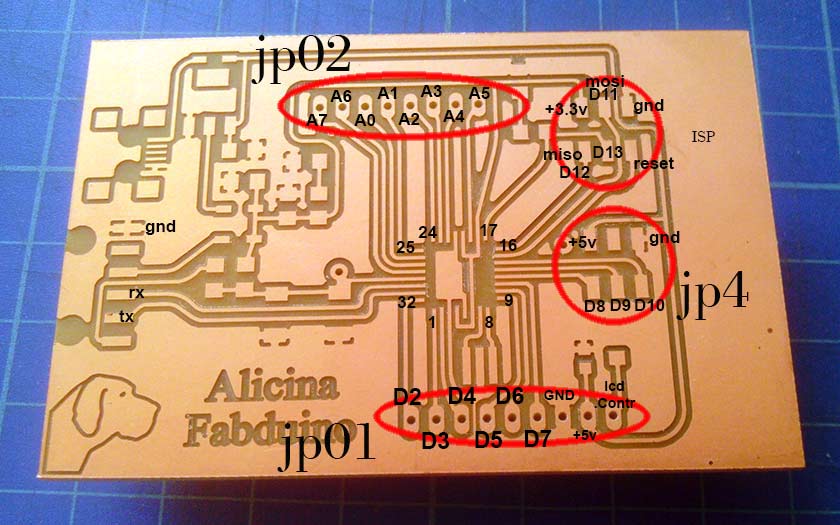
With my fully connected Atmel 328 - Fabuino I'm going to control a stepper motor. Something I will need on my final project. For the moment I will use the Arduino IDE, C++ is still out of my range for now and time is not on my side :-). I started to map my Fabduino pins, using the picture below:
I used an L298N stepper motor driver and old epson printer stepper motor connected to my Fabduino board. Many example were tested and did not work well or did not worked at all, the stepper was just making noise and vibrations but did not move, I thought my DIY board could have problems so I tested those code also on Arduino Uno but they were not working either. Once the right code was found and worked well on the original Arduino, I switched to my Alicina-Fabduino and it worked perfecly. All the problems I had were with the Accelstep library, when I svitched to the older Stepper.h library everything worked fine. As I am hard-headed, I tried again whit the Accelstep.h library, I partially succeed driving a Pololu driver with Step-Dir comunication, after a difficult setup I had the motor running and following my command but the speed and accelleration were very low, a test with original Arduino Uno gaved the same result so I concluded that was not an hardware problem. I am continuosly experimenting to find the best solution to drive the motor with the Step-Dir system, but the new experience with the Gestalt nodes seems to me the best and most versatile solution for my project.
This is the working code that gave no problem at all all the code written with Accelstep library were unsuccessful or worked with a very slow maximum speed no matter what setup I used.
I'm going to experiment now whith an LCD display controlled by an encoder with push button .... work in progress ....
#include Stepper.h

const int stepsPerRevolution = 200;  // change this to fit the number of steps per revolution
// for your motor

// initialize the stepper library on pins 8 through 11:
Stepper myStepper(stepsPerRevolution, 2, 3, 4, 5);

void setup() {
myStepper.setSpeed(60); // set the speed at 60 rpm:
Serial.begin(9600); // initialize the serial port:
}

void loop() {
Serial.println("clockwise"); // step one revolution  in one direction:
myStepper.step(stepsPerRevolution);
delay(500);
Serial.println("counterclockwise"); // step one revolution in the other direction:
myStepper.step(-stepsPerRevolution);
delay(500);
}
5 May Progress
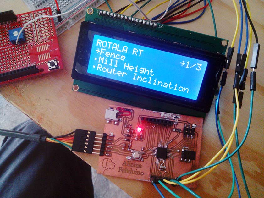
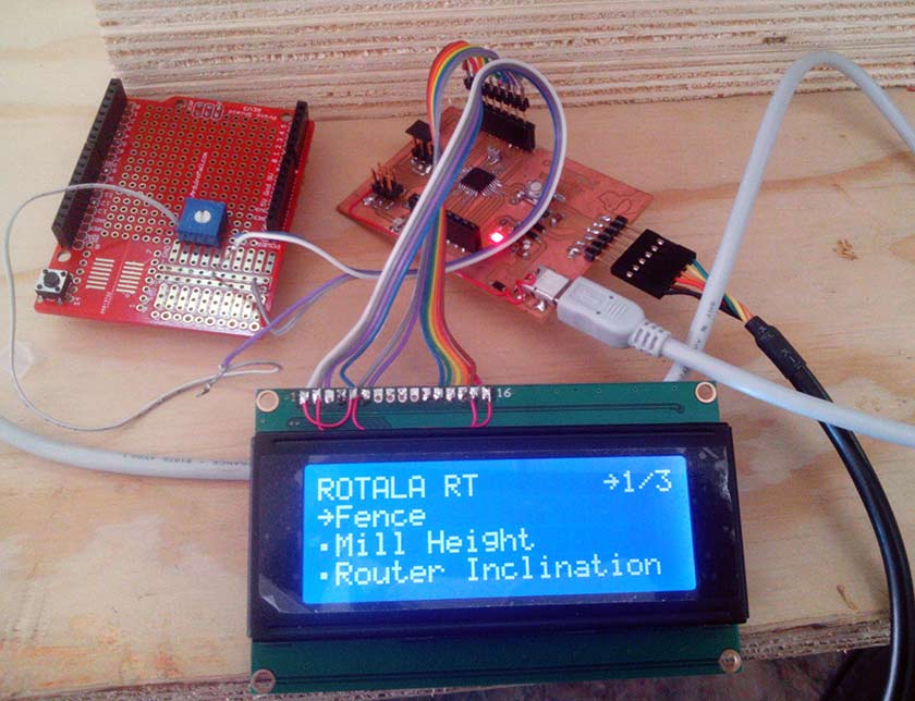
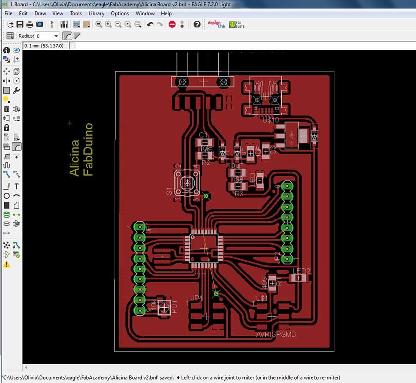
Using the Menwiz library and a 20x4 LCD display Thet Fabduino is bring to life :-). I understood that some minor improvment to the Alicina-Fabduino board are welcomed. First of all I need to route a +5volt signal from the Usb to some of the connectors to help and easy drive of some componets I may need, and the LCD is the first, I also thought it would be nice to easily connect the LCD and a 10k trimmer to drive the luminosity/contrast of the display would help ... so a redesigned the Alicina Board adding a pin to the connector ... ending with the Fabduino v2 Lcd Display edition :-)
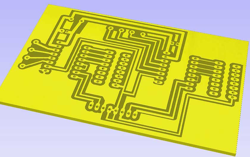
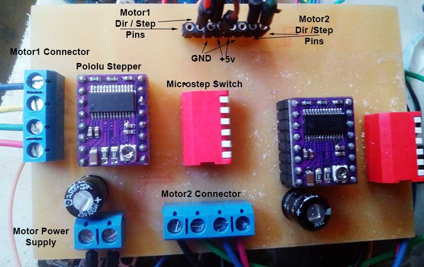
After the test of the Fabduino with the Pololu and stepper motors, the obvious part is to buil a Motor shield to rationalize the wiring, as molex screw conectors are needed, the circuit was made with through the hole technique ... a very relaxing thing after month of surface mounting welding :-). I added some microswitches to control the microstep pins of the Pololu. I think I going to design also a "control shield" that will carry the push buttons and the Lcd Display.