
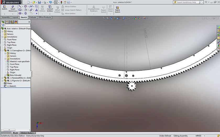
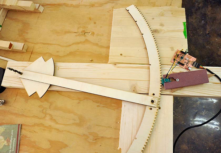
Measurements ... I need for my final project to measure the variable angle between the surface of the table and the mill, this feature will help to make some border joint in a productive and precise way. There are some possibilities to measure an angle, my first idea was to use an encoder with a pinion and a long curved rack with a radius of about 500 mm. After Neil's lesson, I thought it could be nice to try with a two axis accelerometer/position sensor, but with further investigations I realized that It would be very difficult to obtain a precision equal or better than 1 degree ... which is good but I would prefer to reach 0.1 degree, that would be possible with an encoder and the right gears. I also thought to use a stepper motor as an encoder, but with further investigations I understood it's not possible. I designed a basic gear and a curved rack, the size of the teeth was calculated to have 360 teeth on the full circumference and to have one degree each step, a very simple encoder will easily have 12-24 step and that would give me the requested 0.1 resolution.
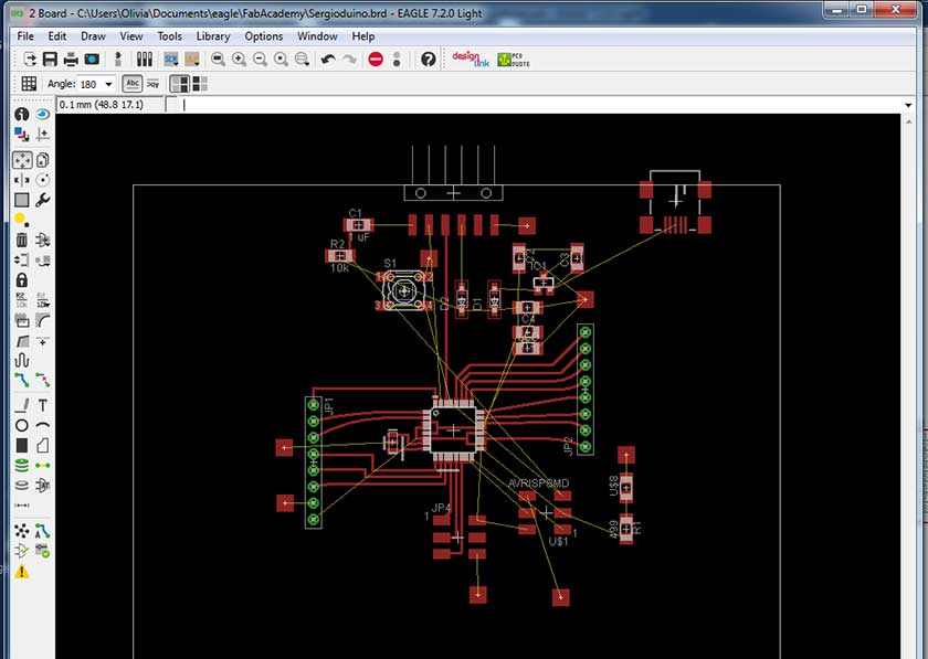
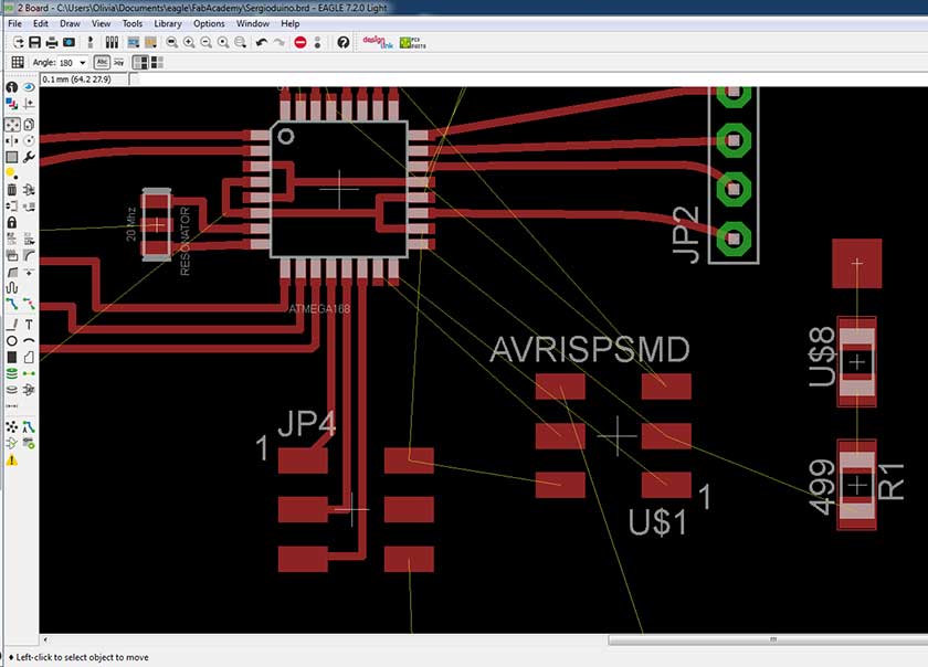
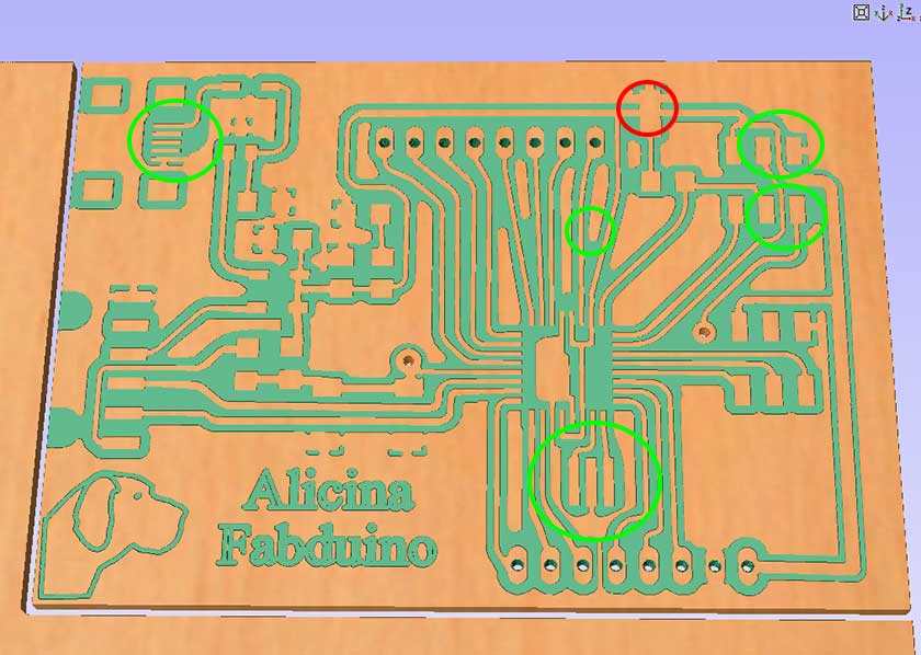
Last thursday I started to think I could never finish this assignment in one week, so I started with a minimalistic work ... "copy and modify a little" what other students did in previous courses ... I was not happy at all, but after a good sleep, I wake up with the motivation with whom I had started the Fab Academy adventure: learn as much as I can, and "copy and modify" isn't the best way. So I started from scratch the design of my Fabduino board with the Eagle software. The beginning was a problem, it was difficult to find the right components in the Eagle library, the design of the circuit was a slow process because my memory on Eagle's commands vanished after some weeks on other assignments. But in the end almost everything was ok ... well except the wrong usb connector and the too small resonator package (red circle = faults).
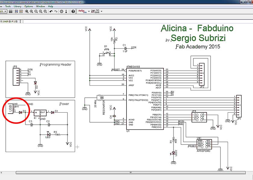
The routing traces it's a nice game :-) but the real "mind game" is the component placement, I was prepared to use some wire bridges, but only one was necessary (from reset pin to the ISP connector). All the pins of the Atmega328 were conected and in my next revision I will try to make the board Arduino shields compatible.
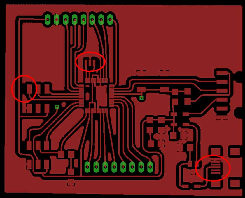
I tried different methods to export the Eagle design: first exporting in dwg/dxf format and then exporting a PNG image at high resolution (1000/1200 dpi).
DWG/DXF and other vector format were very bad and all the vector based programs did not solved easily the problem, a lot of work was needed to have an usable vector file. A better solution was to export a PNG image at high dpi rate and then trace the bitmap in the CAM program some work was still needed but less than the DXF file.
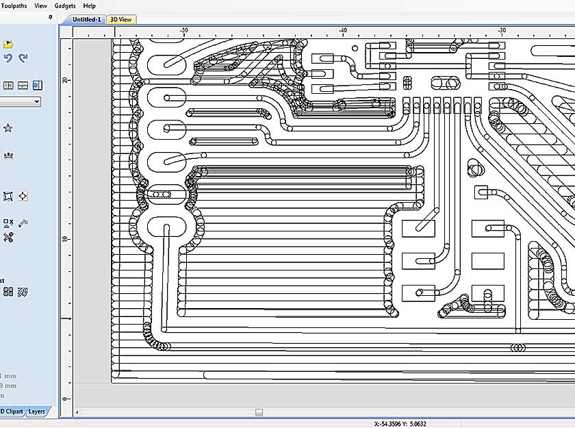
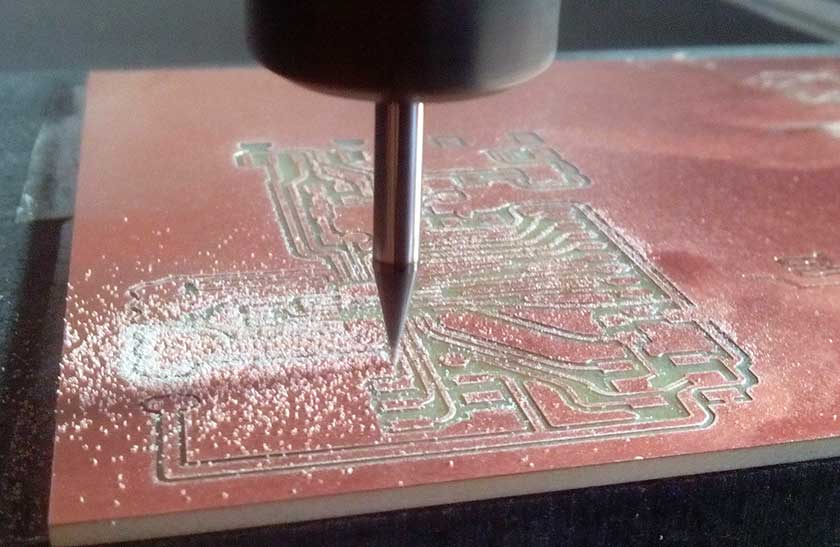
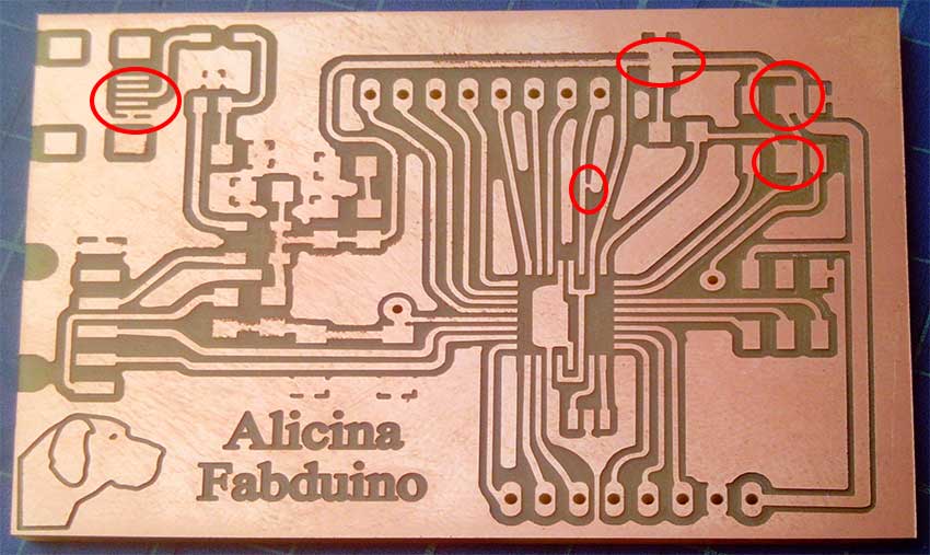
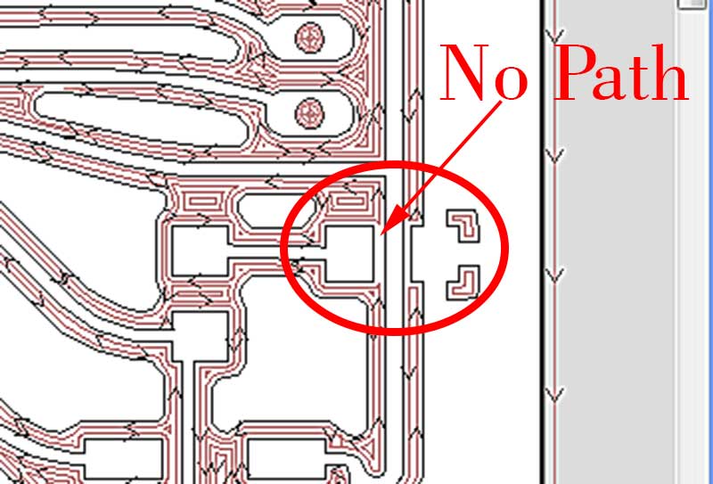
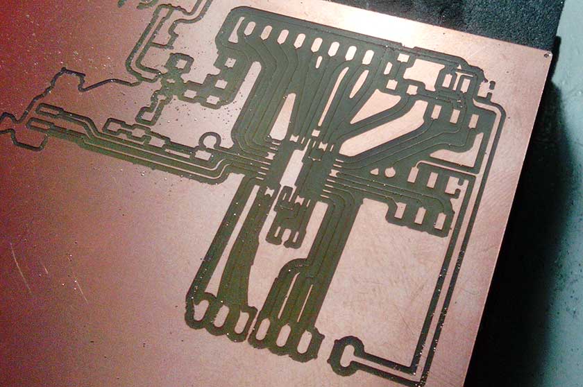
A collection of errors were made, few designing the boards, some on the CAM process and some on the milling process, the first milling try was with an engraving v-bit 0.2mm flat tip 20deg, the preview results were better than the 1/64 inch flat-end mill but as you can see in one of the images, the v-bit was ruined and cutted much larger than expected, another problem with v-bits is that trace dimension is affected by depht of cut, so a precise Z zero and a perfecly leveled base are mandatory. Using the 1/64 end mill is easier but I had to modify some traces and pads where it was not possible for the mill to pass through. Finally the result was great with just few correctable errors.
The soldering process was tricky, but now I manage the small component much better now. After a carefully check, I eliminated some few short circuits before the smoke test, except one which was shorting VCC and GND under the led on pin 17. Luckily no smoke, just a diode too hot found touching the board with a thumb.
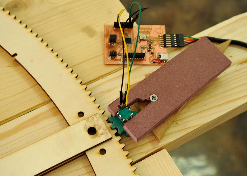
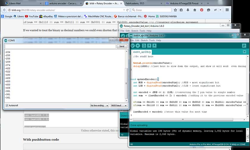
Even there, finding a working code was hard. The working code I finally found, did counted the impulses on the serial monitor, but I couldn't get any conversion to my desired unit: the degree. .... still lot of exercise to do ... work in progress ....
 t
t