
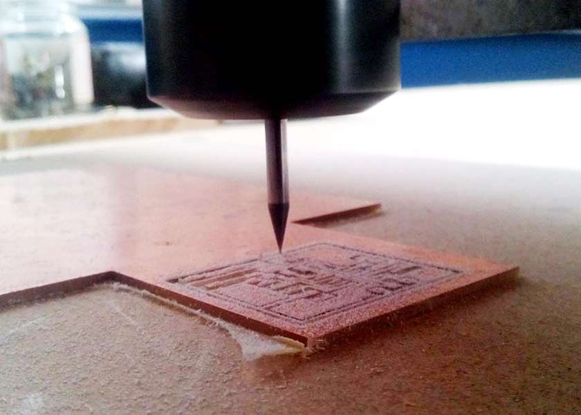
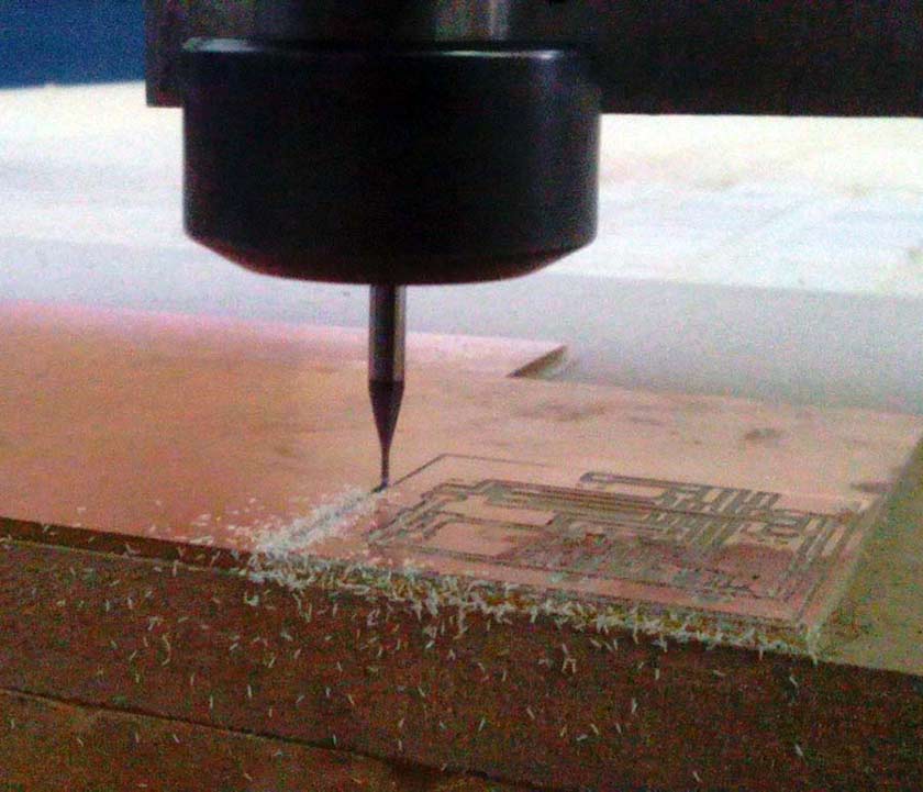
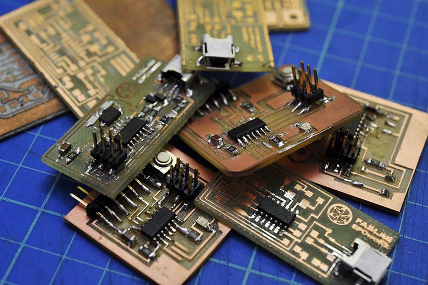
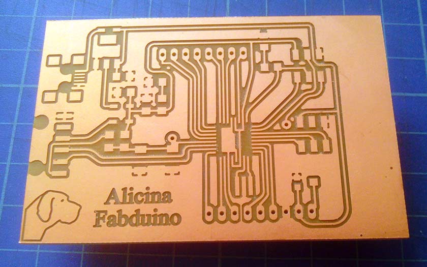
Following Fab Academy Eagle tutorial it was easy to begin circuit design, but my result did not satisfy me for two reasons: the first was the look of the circuit, such a simple style :-) the second is that the simple style is also milling time (and end-mill bit) consuming, you have to remove much more material. Eagle has a very simple command: ratsnest ! it creates a ground plane design which gives better reliability, and in the same way you can "fill" with copper other areas. This is my procedure: Step one: Start with a board where you have routed all the signals except ground. Choose "Polygon" tool, be sure you selected the correct layer in the Parameter toolbar than set "width" and "Isolate" values. This is the recommendation from Eagle's help menu: "You should avoid using very small values for the width of a polygon, because this can cause extremely large amounts of data when processing a drawing with the CAM Processor.The polygon width should always be larger than the hardware resolution of the output device. For example when using a Gerber photoplotter with a typical resolution of 1 mil (thousandth of an inch), the polygon width should not be smaller than, say, 6 mil. Typically you should keep the polygon width in the same range as your other wires" I chosed 0.4mm (millimeters). Isolate value determines the distance between the polygon area and the other signals on the same layer. Make sure this is larger than the minimum trace your mill bit is capable. In this example, I chose 16 mils (mils is another unit dimension, it's equal to 1 inch/1000).. To mill the circuits, our small mill was hurted and the spindle axis was damaged ... so we tested the other router mill we had ready ... "the Mechmate" 3x2 meters CNC Router with it's 2.2Kw inverter motor ... a real giant ! well it worked as a very "Gentle giant" all of our pcb board were very well milled and no broken 1/64 end-mill !
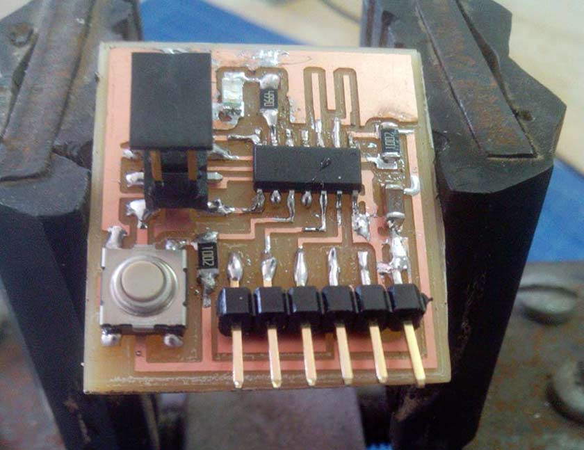
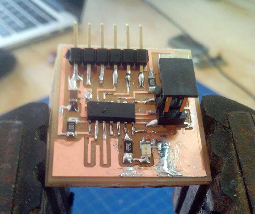
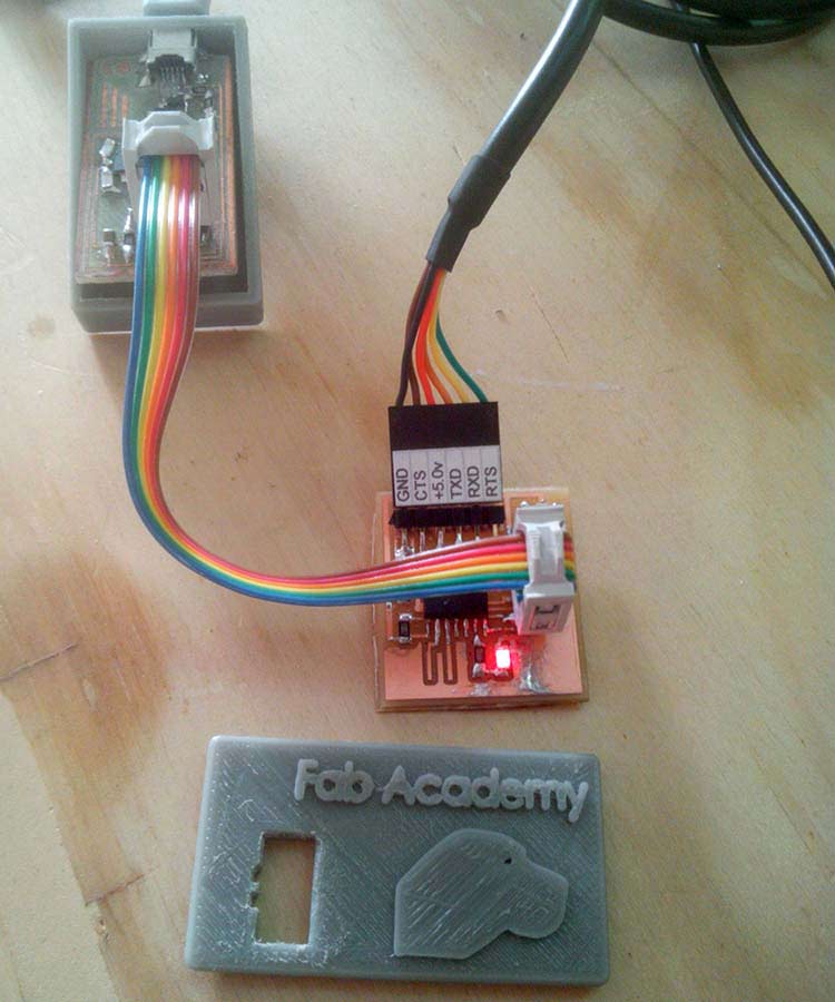
13 of May Update The vesion 2 of my Fabduino board is milled, The improuvement over the v1 is the possibility to connect directly an LCD Display, control the contrast with a 10k pot and give directly the +5v taken from USB.
May Update: Deeper understanding !!
The inspiring work of Daniele Ingrassia student of Fablab OpenDot Milan pushed me to a deeper understanding of what I'm doing.
One of the questions was: why on the improvement list of his Satshakit he states "crystal instead of resonator" ? Why a crystal is a better option compared to a ceramic resonator ?
This is the answer I found:
"gbarry": "An oscillator is an amplifier circuit, with feedback so that it oscillates, and a "frequency a element" that keeps it oscillating at the desired frequency. A crystal can be made for a precise frequency, and it will drift very little if the temperature stray capacitance changes. It is also very efficient and requires very little power to keep it oscillating. Crystals are usually made of quartz, and you pay for all the above features.
Resonators are made from ceramic elements rather than quartz. They do not hold their frequency as well. This may not be important for a microprocessor, but will be important if the circuit is used in a radio, a clock, or other timing-critical applications. They cost less and so are used where stability isn't as important."
Another opinion "Guillelm Planisi":
Resonator accuracies are in the order of 0.1 to 1%. Enough for USART comms, and for some time measurements, but not enough precise to keep time by RTC.
Crystals have precisions in the range of 10 to 50 ppm (parts per million), much better than resonators, so they are good if you need pretty accurate timming measurements and/or RTC.
BTW, RTC accuracy can require much more precission than many other applications. 5 secons per day may be too much to be accepted, and this is about 57 ppm's.
And a here you find deeper explanation with comparison table.