Hot wire Cutting

machine design project made in Rome

GOAL


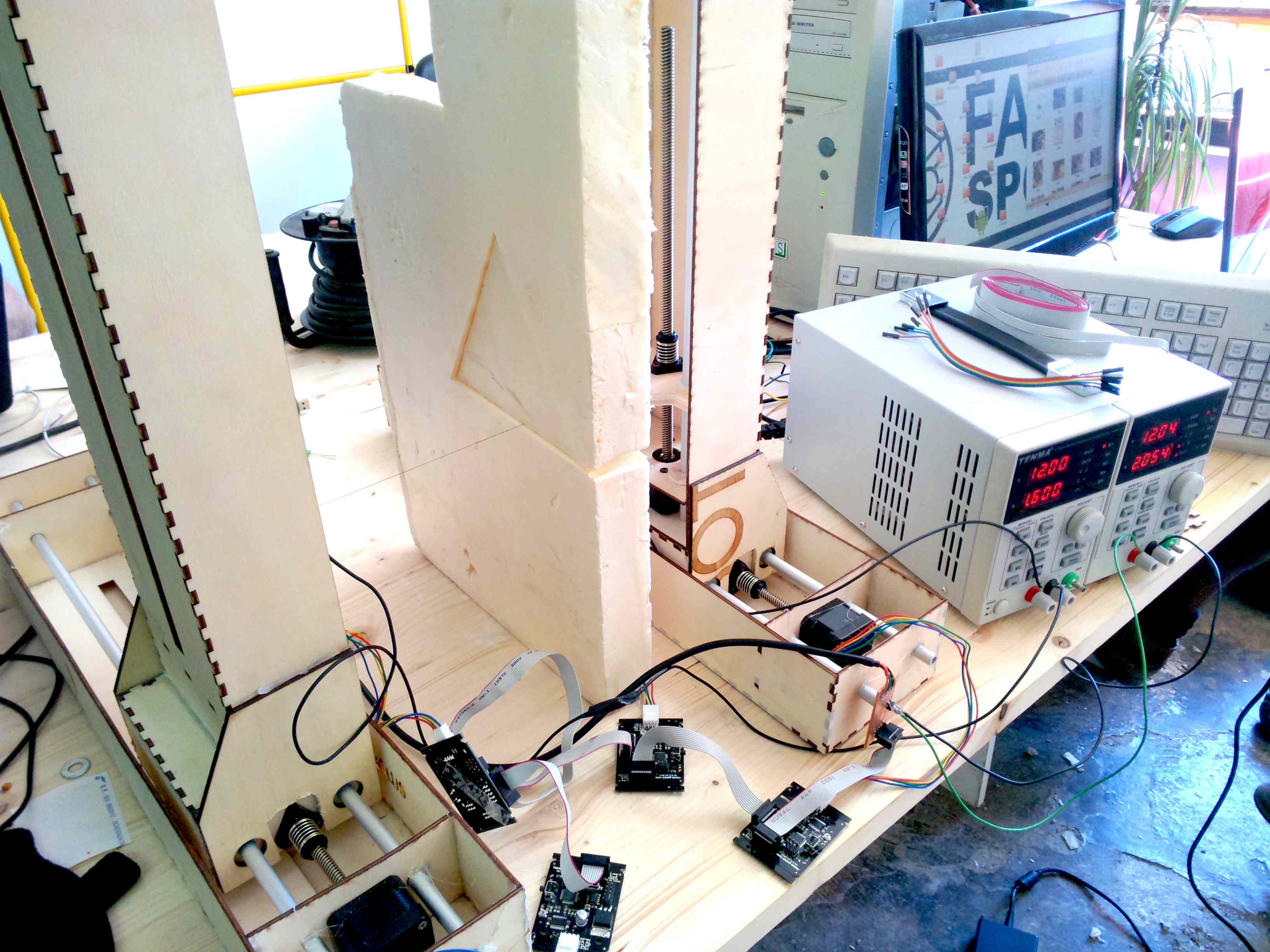
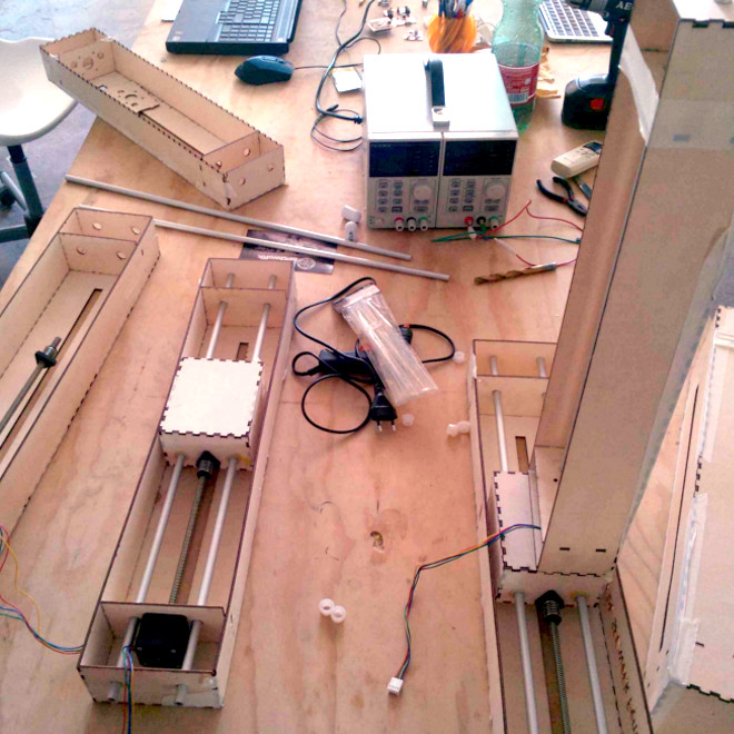
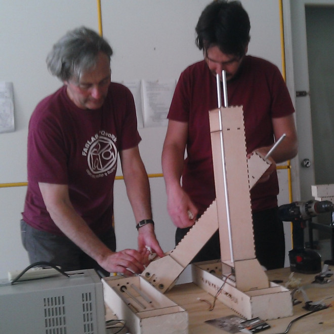
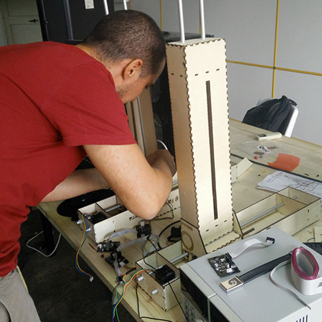
Make a hot wire cutter. We wanted to understand Gestalt and built a useful machine for our Lab. Here there is a list of the tutorials, steps, machine, tools and skills required:

  • Tutorials - MTM - MTM2 - PyGestalt - As220
  • Steps - frame design, assembly, programming PyGestalt, test
  • Machines - Laser Cutter and CNC
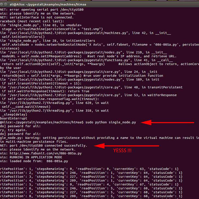
  • Tools - FabAcademy Kit + Solid Works + PyGestalt + Python + Ubuntu
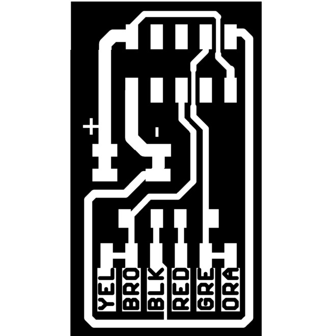
  • Skills - draw with Solid Works - press fit constructions - mill and stuff pcb (FabNet) - work with Ubuntu's terminal - understand how to use PyGestalt

The Team


Work in Progress


First of all we divided in 2 groups: one for the Frame (Tommaso and Antonio) and the other for Programming (Sergio and Alessandro).
Frame
Starting from Nadya's design Tommaso and Antonio redesigned the drawings with Solid Works. They did some test with cardboard but, due to the huge thickness, they realize that this kind of cardboard was not suitable to the project. Furthermore (and this is crazy) in Rome it's easier and cheaper to buy plywood instead of cardboard. So, once get the plywood, they cut it through the laser-cutter (Recommended Laser setting for Triunph 80 Watt: - Playwood 3mm - Cut: Speed 10, Power 70, Corner Power 60 - every laser/cardboard is different... test it first!). Below you can download our cut files, enjoy! Then the assembly of the structure was simple thanks to our press-fit. Anyway we decided to strengthen the structure with two side reinforcements for each vertical "tower". Finally we shaped two pieces of wood with the CNC, as hot-wire's holder.
Programming
Once the Fabnet was easily milled and stuffed we carefully connected all the components . The first step was to install the pygestalt and relative utilities and thanks to Shawn's tutorial(up, As220) was quite easy. Then we had some hard time in order to make the Gestalt Nodes communicate with our pc (we used linux ubuntu). Luckily the solution was easier than what we expected: thanks to Alessandro's suggestion, we discovered that to activate the USB serial communication you need SUDO permissions. We managed also to estabilish the communication with Alessandro's Mac. Then we started to use and study the single_node.py and the two nodes xy_plotter.py in order to better understand the functioning. Inside the code we learned that at beginning there are the libraries, then the nodes definitions and the unit (mm) used for coordinates, the block to calibrate the machine, the velocity request that define the speed of the machine and finally the coordinates of the movements of each axis. Another important thing is to delete test.vmp every time you need to reconfigurate the network and the axis. Happily we managed to make our machine working with four axis by changing the coordinates. Further you can watch our video! At this time the next step is to find a way to make it read a G-code file. See below the student's machine design pages in order to go deeper in this project.

FINAL TEST


Watch also our Final Review Presentation during "Fab Academy 2015" from minute 1:08:30 HERE :D

special thanks to


Emma Pareschi and Zaerc from Waag Society for their help - Massimo Menichinelli for his support - Shawn Wallace from As220 for the tutorial
- and obviously Fab Lab SPQwoRk