Week Task
Individual assignment:design, build, and connect wired or wireless node(s)with network or bus addresses
group assignment:send a message between two projects
Introduction
Network communication, or internetworking, defines a set of protocols (that is, rules and standards) that allow application programs to talk with each other without regard
to the hardware and operating systems where they are run. Internetworking allows application programs to communicate independently of their physical network connections.
There are different types of network protocols
•Transmission Control Protocol (TCP):a connection-oriented communications protocol that facilitates the exchange of messages between computing devices in a network. It is the most common protocol in networks that use the
Internet Protocol (IP); together they are sometimes referred to as TCP/IP.
•The Internet Protocol (IP): is the principal communications protocol in the Internet protocol suite for relaying datagrams across network boundaries. Its routing function enables internetworking, and essentially establishes
the Internet.
•The Hypertext Transfer Protocol (HTTP): is an application protocol for distributed, collaborative, hypermedia information systems.HTTP is the foundation of data communication for the World Wide Web, where hypertext documents
include hyperlinks to other resources that the user can easily access, for example by a mouse click or by tapping the screen in a web browser.
•Hyper Text Transfer Protocol Secure (HTTPS): HTTPS is a standard protocol to secure the communication among two computers one using the browser and other fetching data from web server. HTTP is used for transferring data
between the client browser (request) and the web server (response) in the hypertext format, same in case of HTTPS except that the
transferring of data is done in an encrypted format. So it can be said that https thwart hackers from interpretation or modification of data throughout the transfer of packets.
•Ethernet: is the most widely installed local area network (LAN) technology. Ethernet is a link layer protocol in the TCP/IP stack, describing how networked devices can format data for transmission to other network devices on
the same network segment and how to put that data out on the network connection
• Post office Protocol (POP): POP3 is designed for receiving incoming E-mails. etc
Communication
Communication between two MCU is called embedded communication.To perform the communication one of the MCU act as a Sender and other to be as a receiver.MCU communications may in one
direction or both, depends on the users choice. There are two types of communication, serial and parallel. The crucial difference between serial and parallel communication is that in serial communication a single communication link
is used to transfer the data from an end to another. As against in parallel communication, multiple parallel links are used that transmits each bit of data simultaneously.
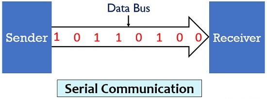
• Serial Communication:In serial communication the data bits are transmitted serially over a common communication link one after the other.Basically it does not allow simultaneous transmission of data because only a single
channel is utilized. Thereby allowing sequential transfer rather than simultaneous transfer.
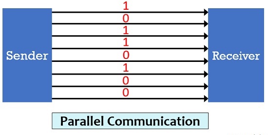
•Parallel Communication:In parallel communication the various data bits are simultaneously transmitted using multiple communication links between sender and receiver. Here, despite using a single channel between sender and receiver, various links are used and each bit of data is transmitted separately over all the communication link.
I2C Protocol
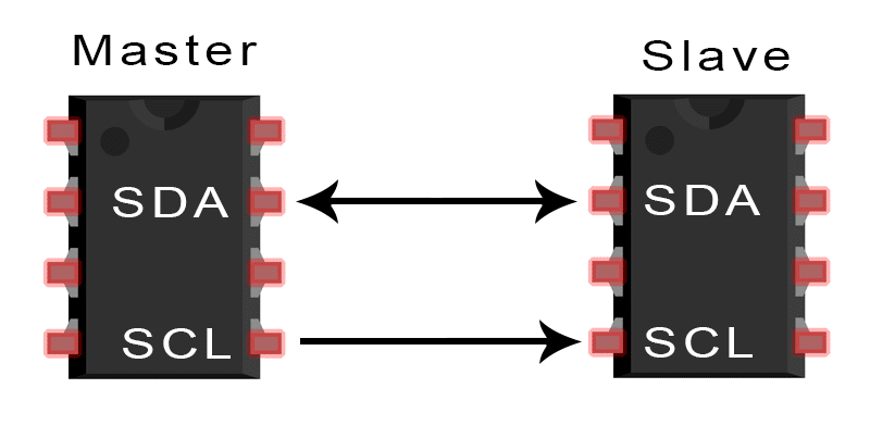
I2C is a serial communication protocol, so data is transferred bit by bit along a single wire (the SDA line). With I2C, we can connect multiple slaves to a single master (like SPI) and we have multiple masters controlling single, or multiple slaves. This is really useful when we want to have more than one microcontroller logging data to a single memory card or displaying text to a single LCD.
Group Assignment
The task for the week is to Send a message between two projects.In this week we have studied communication protocol like I2C,RS232,SPI.We have used I2C protocol for communicating between LCD and 328P board. For more details click here
Individual Assignment
The task for the week is to design, build, and connect wired or wireless node(s)with network or bus addresses.
I have designed two board i.e. master and slave board. I use Fab Academy board and re-route it. Currentlly I dont have lab access due to Lockdown for COVID-19. So for this assignment, I will design board and when i have lab access, then i wil mill it and test it.
So practise purpose here I am trying to develope the network for ARDUINO board using TinkerCad.
RS232 Serial Bus Communication
Step1: For this communication, we required master and slave board(i.e.bridge and node). I refer the Fab Academy Bridge board and Node Board . Rerouted the board.
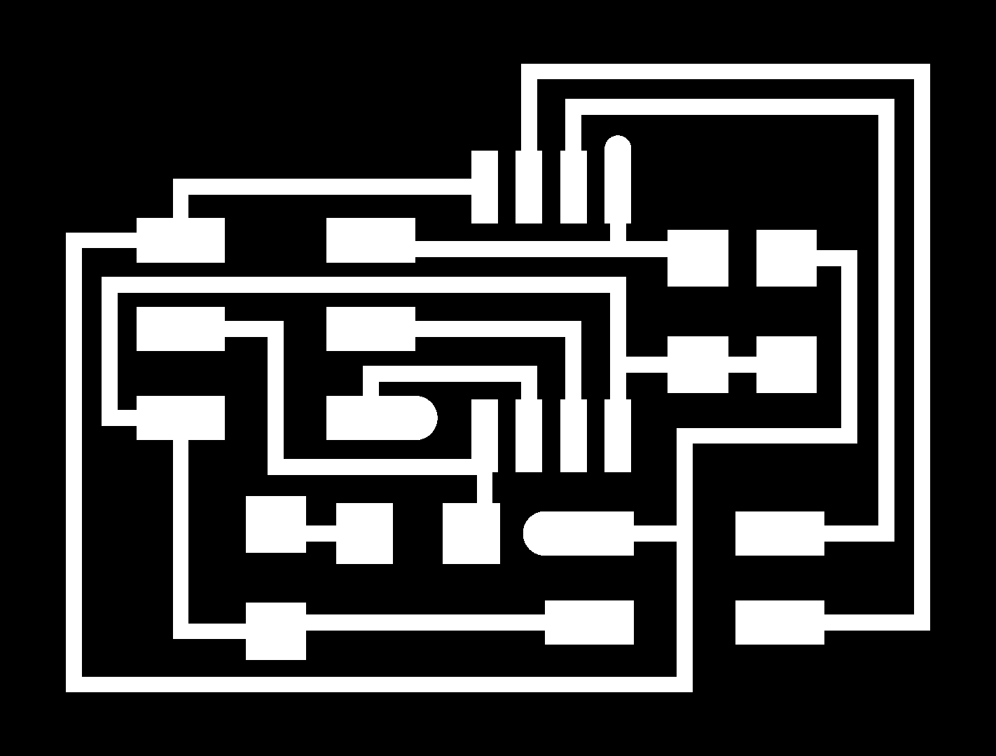
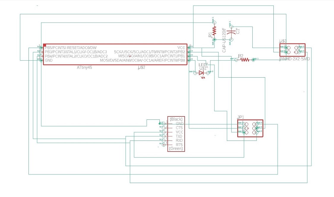
Bridge Board- This board communicates with the serial port and other board with the help of FTDI cable. This is a device or a process, which always controls other devices or processes. The schematic of Bridge board is here
The final Bridge board with all components name is shown belows
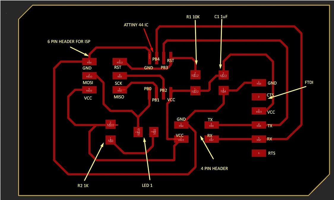
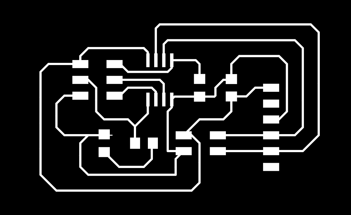
Node Board: This board is connected with Bridge board to receive the signal. The "Node" can only receive it and inform the Bridge about the receiving the data. The "Node" doesn't have any control to stop receiving the data. The schematic of the Node Board is here
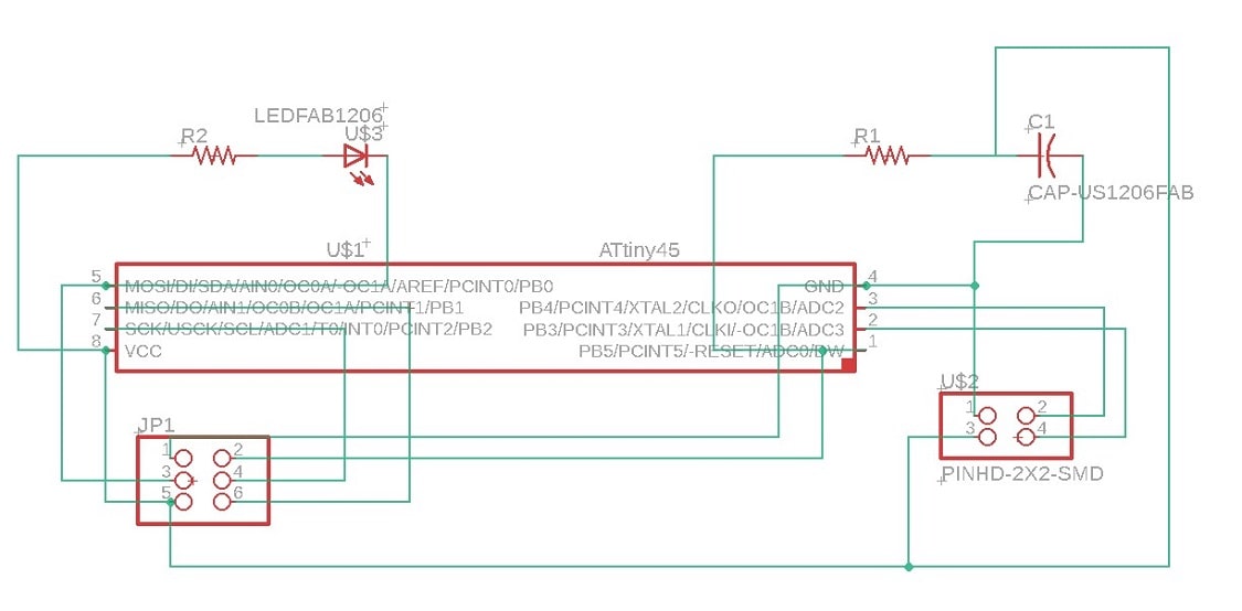
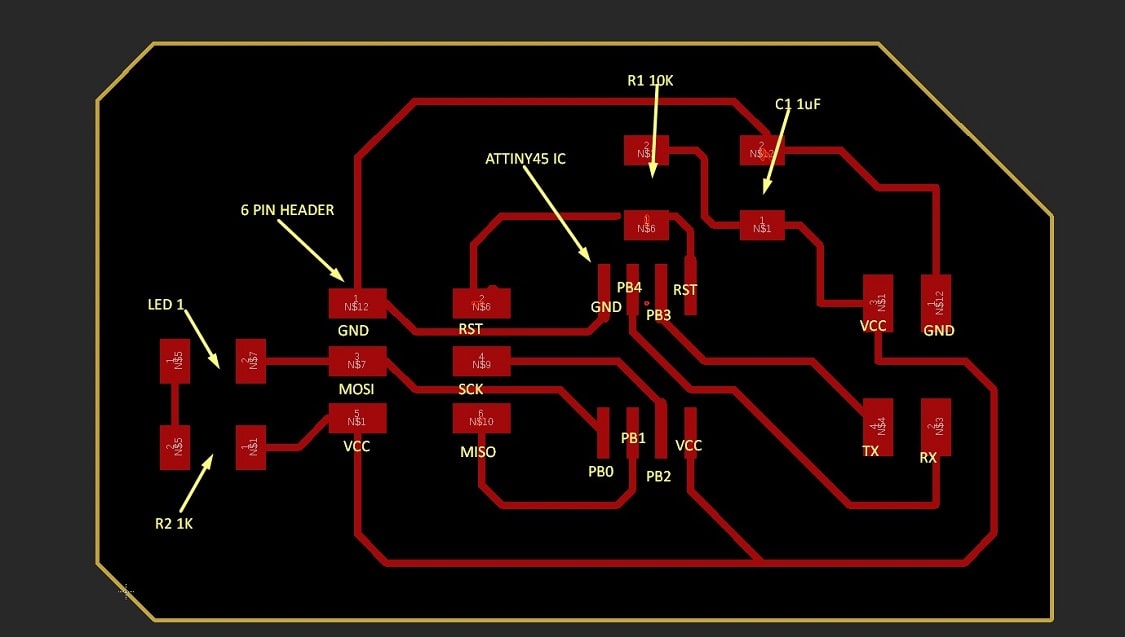
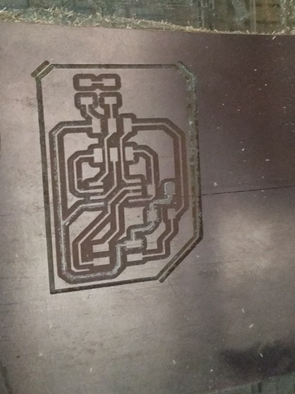
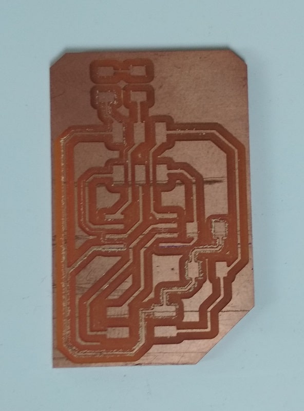
The trace and component of the Node board is here
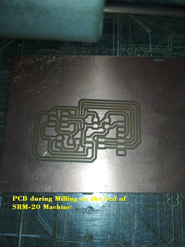
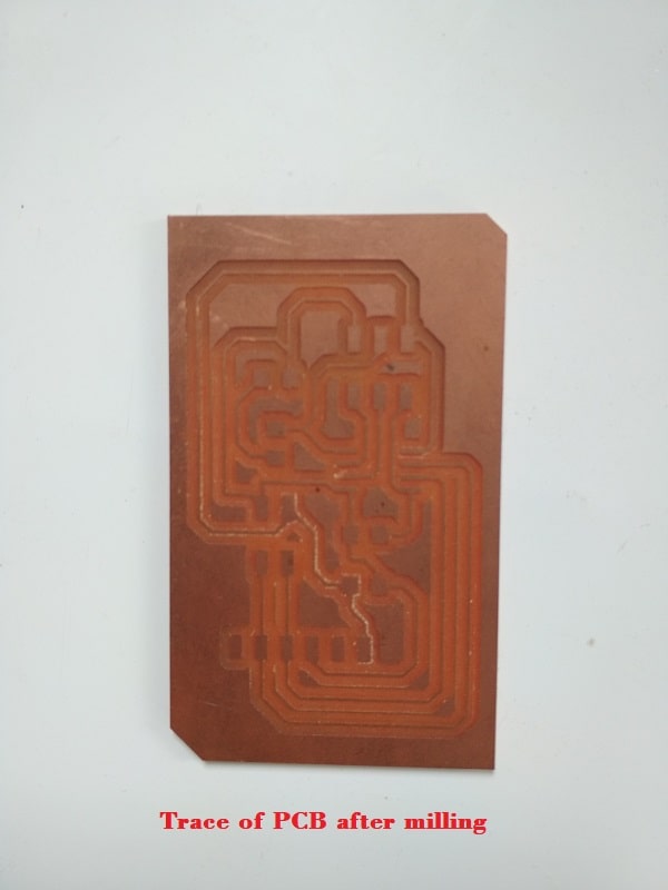
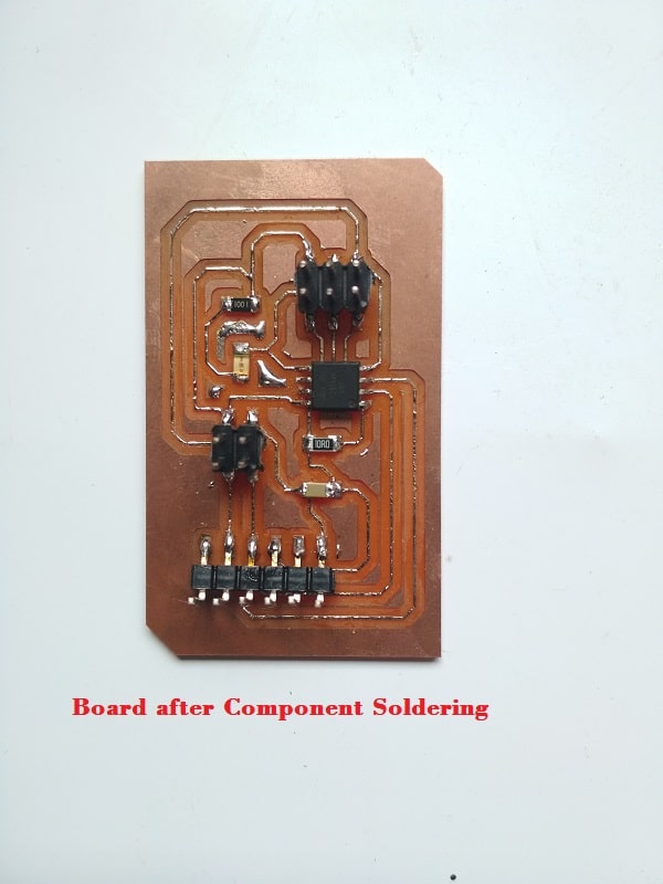
Step 2: Milling and Soldering-The board is milled using SRM-20 milling machine. The detailed process of milling using SRM-20 milling machine is provided in Assignment5:Electronic Production.
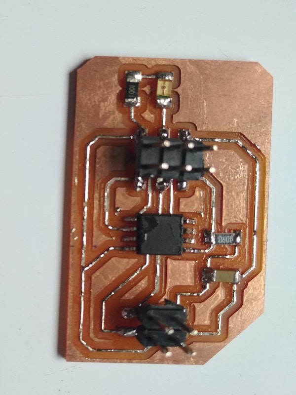
The Bridge Board after milling and soldering is here
The Node Board after milling and soldering is also here
Step 3:For programming board I used Fab ISP (i.e.usbtiny)and Arduino as a FTDI cabel for serial communication.Connect your usbtiny (Fab ISP) to the hello.bus.45.bridge board's Fab ISP port using the Fab ISP cable, and connect FabISP to the USB port of the computer.
Here I am using Arduino IDE for programming. Click on tools>select Board, Processor,Clock and Programmer>click on Burn Bootloader.
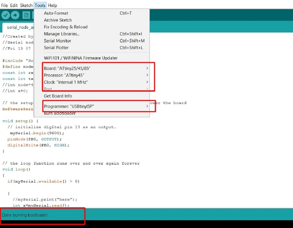
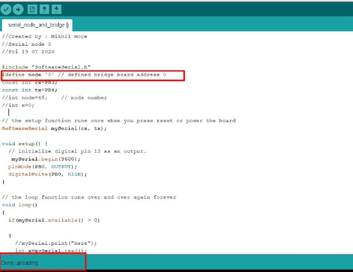
In the code, we define the bridge board address 0. (means when we press 0 on serial monitor>LED of bridge board will blink). Then click on compile>after compiling sketch>upload the code.
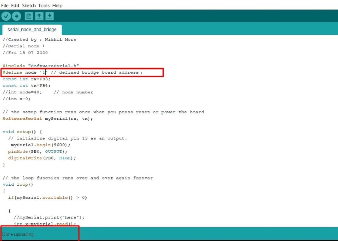
Simillarly I have uploaded code in Node Board, the code is same for the Node also, only the difference is to changes the board address, here we put board address 1. (means when we press 1 on serial monitor>LED of Node board will blink)
Step 4: Testing - For testing purpose, I am using Arduino board as FTDI cable, the arduino board is connected to the computer and then Bridge board is connected to arduino, the connection is as like below
5V ARDUINO -->VCC Bridge
GND-->GND
RX-->RX
TX-->TX
Simillarly connection made for NODE and BRIDGE. When I pressed "0" on serial monitor, then LED of Bridge board is blinked and when "1" pressed, LED of Node board is blink.
Radio Frequency Bluetooth Communication
In the Assignment 13:Interface and Application Programming, I have tried to controll the Fan ON/OFF using the android app in Mobile phone. For the communication between the mobile phone and the microcontroller board, I am using Radio Frequency Bluetooth Communication. The bluetooth model is connected to the microcontroller board using ATTINY 44 IC and it is connected with bluetooth of mobile phone with this communication I am controlling the Fan ON/OFF. For more details, please visit Assignment 13 . Here is the video of communication.
What i learn?
I am learn about
1. About diffrent protocol for communication
2. Serial and Parallel Communication
3. How to establish RS 232 serial bus communication
4. How to extablish RF bluetooth communication
5. Board development for Networking and Communication
Go to the top
Download original file hereBack
Assignment 16: Molding and Casting
Pattern is the principal tool during the casting process. It may be defined as a model of anything, so constructed that it may be used for forming an impression called mould in damp sand or other suitable material.

Fab Academy Course on Digital Fabrication by Nikhilkumar More is licensed under a Creative Commons Attribution-NonCommercial 4.0 International License.
Based on a work at http://fabacademy.org/2020/labs/vigyanashram/students/nikhilkumar-more/.
Permissions beyond the scope of this license may be available at http://fabacademy.org/2020/labs/vigyanashram/students/nikhilkumar-more//contact.html