Computer-Controlled Machining
Week Task
group assignment: test runout, alignment, speeds, feeds, and toolpaths for your machine
individual assignment: make (design+mill+assemble) something big
Introduction
Computer-Controlled Machining is the use of software and machinery to automate a manufacturing process.There are three components of CAM
1. Software- It is tells a machine how to make a product by generating toolpaths.
2. Machinery- It can turn raw material into a finished product.
3. Post Processing- It can converts toolpaths into a language machines can understand.
The enginerrs can develop the design of madel using CAD software. Design is either 2D or 3D design. The design contains a set of physical properties that will be used by a CAM system.
When a design is complete in CAD, it can then be loaded into CAM. This is traditionally done by exporting a CAD file and then importing it into CAM software.
Once your CAD model is imported into CAM, the software starts preparing the model for machining. Machining is the controlled process of transforming raw material into a defined shape through actions like cutting, drilling, or boring.
What is the function of CAM software?
CAM software prepares a model for machining by working through several actions, including:
1.Checking if the model has any geometry errors that will impact the manufacturing process.
2. Creating a toolpath for the model, which is a set of coordinates the machine will follow during the machining process.
3.Setting any required machine parameters including cutting speed, voltage, cut/pierce height, etc.
4. Configuring nesting where the CAM system will decide the best orientation for a part to maximize machining efficiency.
Once the model is prepared for machining, all of that information gets sent to a machine to physically produce the part. However, we can’t just give a machine a bunch of instructions in English, we need to speak the machine’s language. To do this we
convert all of our machining information to a language called G-code. This is the set of instructions that controls a machine’s actions including speed, feed rate, coolants, etc.
G-code is easy to read once you understand the format. An example looks like this:
G01 X1 Y1 F20 T01 S500
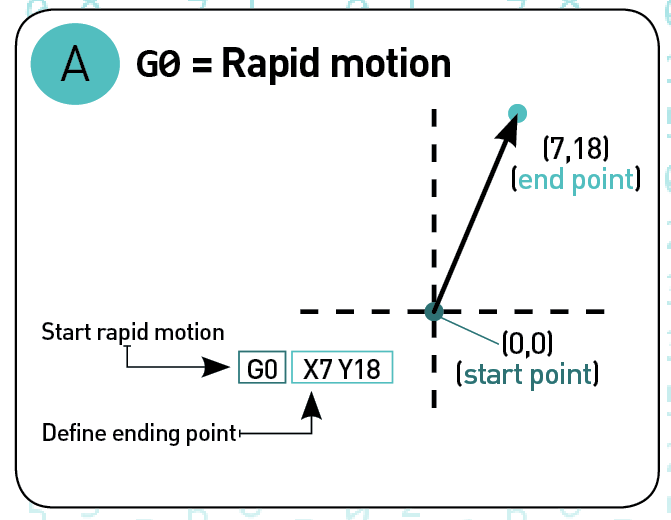
This breaks down from left to right as:
G01 indicates a linear move, based on coordinates X1 and Y1.
F20 sets a feed rate, which is the distance the machine travels in one spindle revolution.
T01 tells the machine to use Tool 1, and S500 sets the spindle speed.
Once the G-code is loaded into the machine and an operator hits start, our job is done. Now it’s time to let the machine do the job of executing G-code to transform a raw material block into a finished product.
Source:https://www.autodesk.com/products/fusion-360/blog/computer-aided-manufacturing-beginners/
Different CAM Machine
1. CNC Lathe Machine
2. CNC Milling Machine
3. Abrasive Jet Machine (AJM)
4. Ultrasonic Machine(USM)
5. Ion-Beam Machine(IBM)
6. Plasma Arc Machine(PAM)
6. Electrical Discharge Machine(EDM)
7. Laser Beam Machine (LBM)
8. Electro-Chemical Machine (ECM) etc.
Group Assignment
The task for group assignment is to test runout, alignment, speeds, feeds, and toolpaths for our machine. This group assignment we have perform at Fab Lab, COE, Pune. The assignment is available on our group member Tejaswini website, so lets click for more details. CAM Group Assignment
Individual Assignment
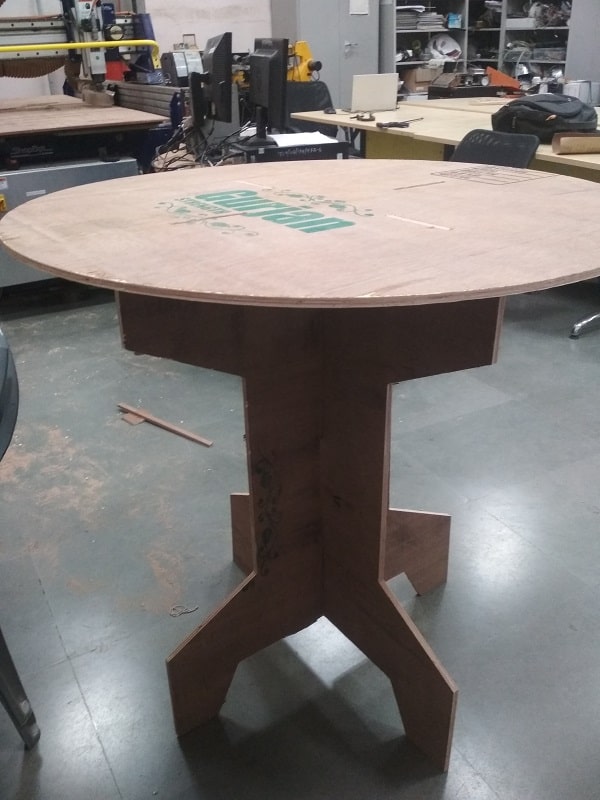
The task for the week in individual assignment is to make (design+mill+assemble) something big using CAM Machine. So here in this assignment Prof. Neil suggest to use ShopBot Machine to cut a plywood material and develope a furniture on it which is helpful for Fab Lab.So went to Fab Lab, College of Engineering (COE), Pune for this assignment. Firstly we develop we develop our design using CAD software, then loaded that design on machine using CAM software and then machined the design and assemble it. so lets start!
CAD Design
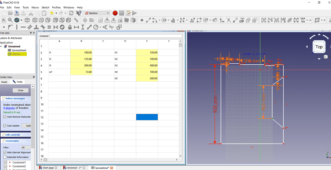
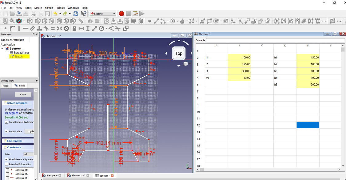
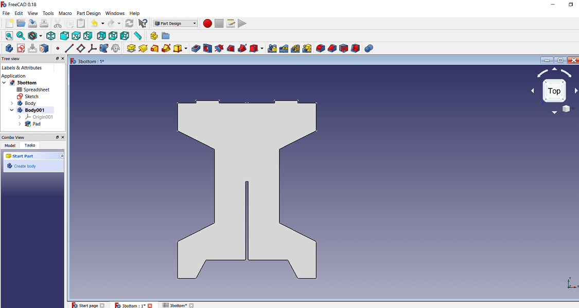
For CAD design of the model, i have used FreeCAD software.I have develop the projector table .Object is divided into three parts. So i have develop the three design and then this design is assemble in the same software. The dimension of the object is set using the Spreadsheet.Because if any changes is required in the dimesion, that i can directly do in the spreadsheet.Following is the first part of the object.
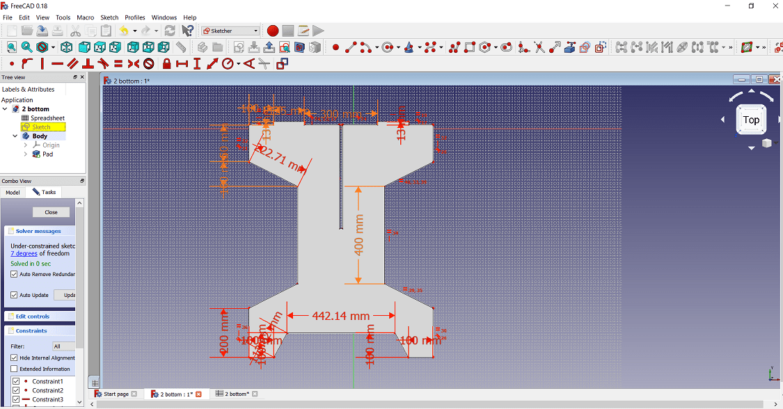
The second part of the object
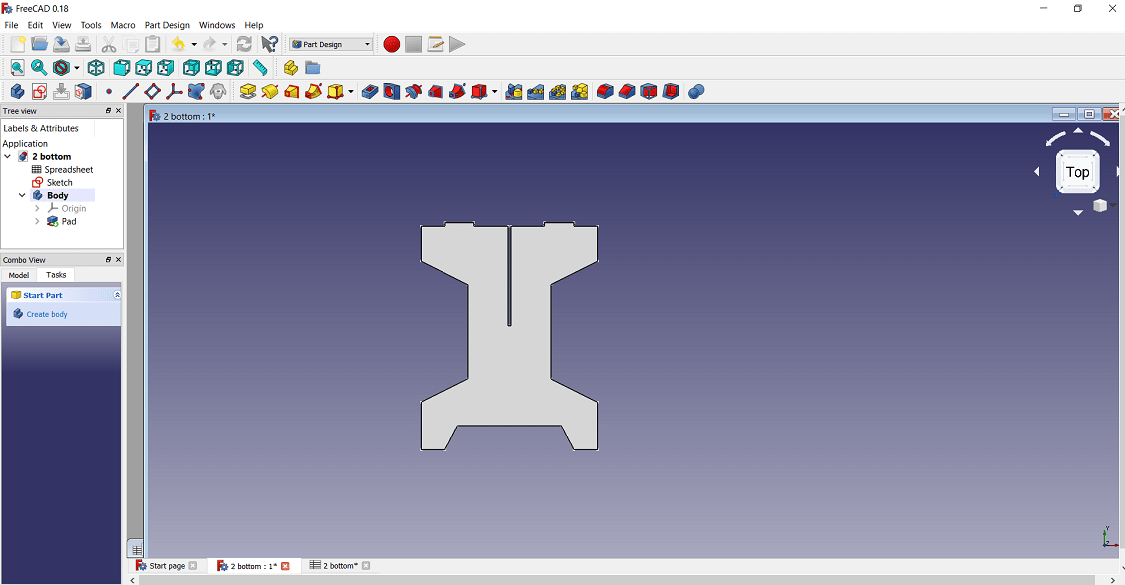
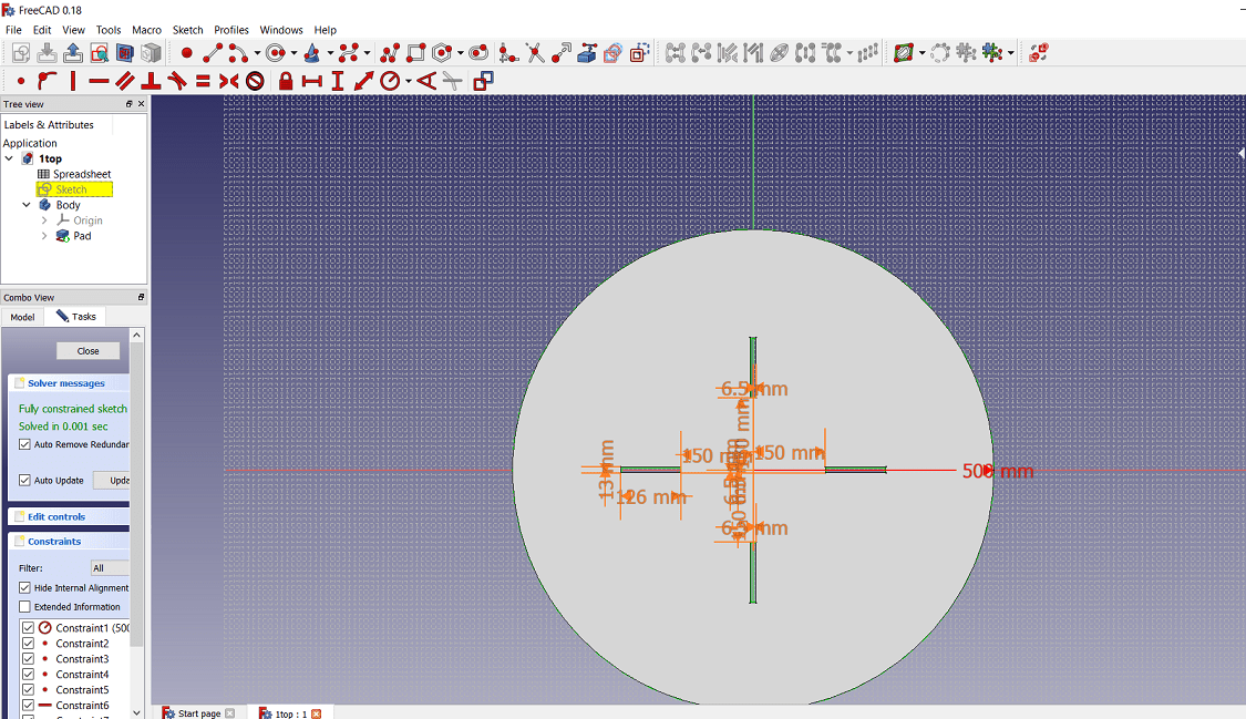
The third part of the object
The final assembly is done using A2plus menu in FreeCAD.Following is the some screenshot of assembly
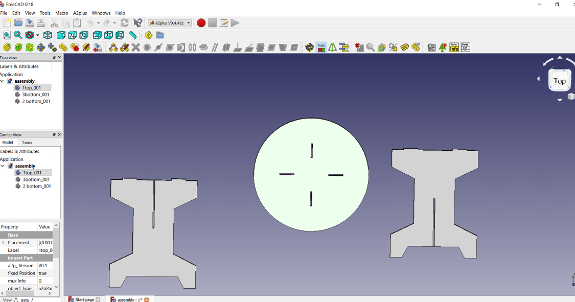
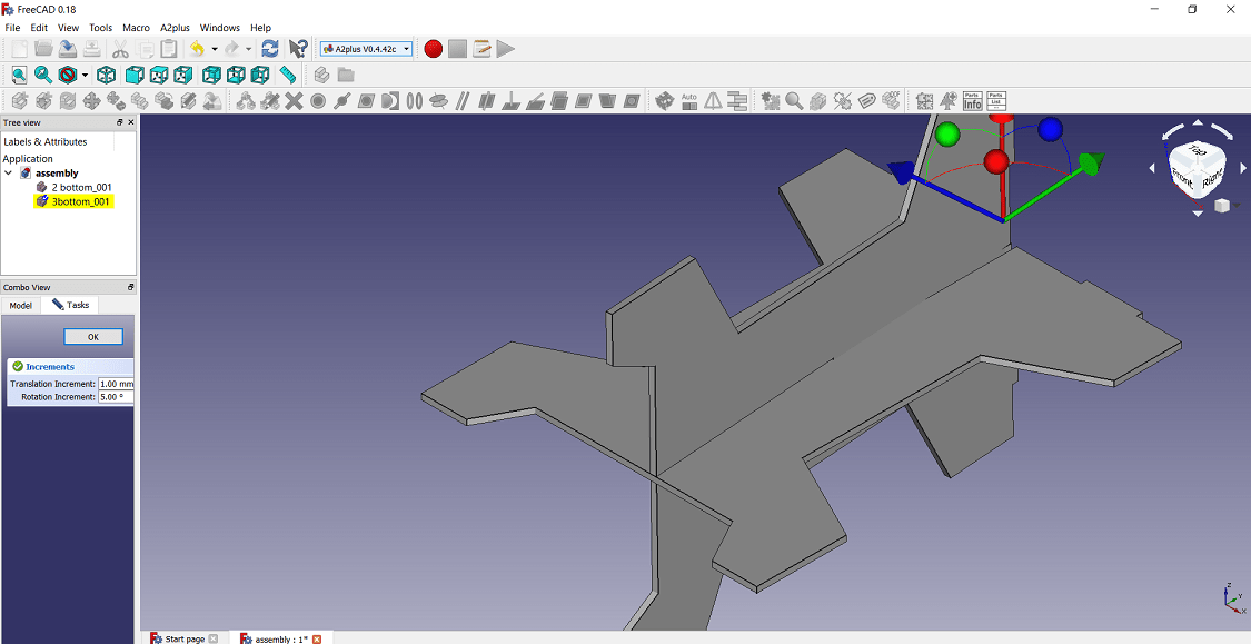
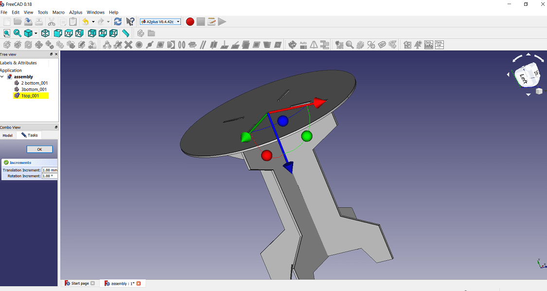
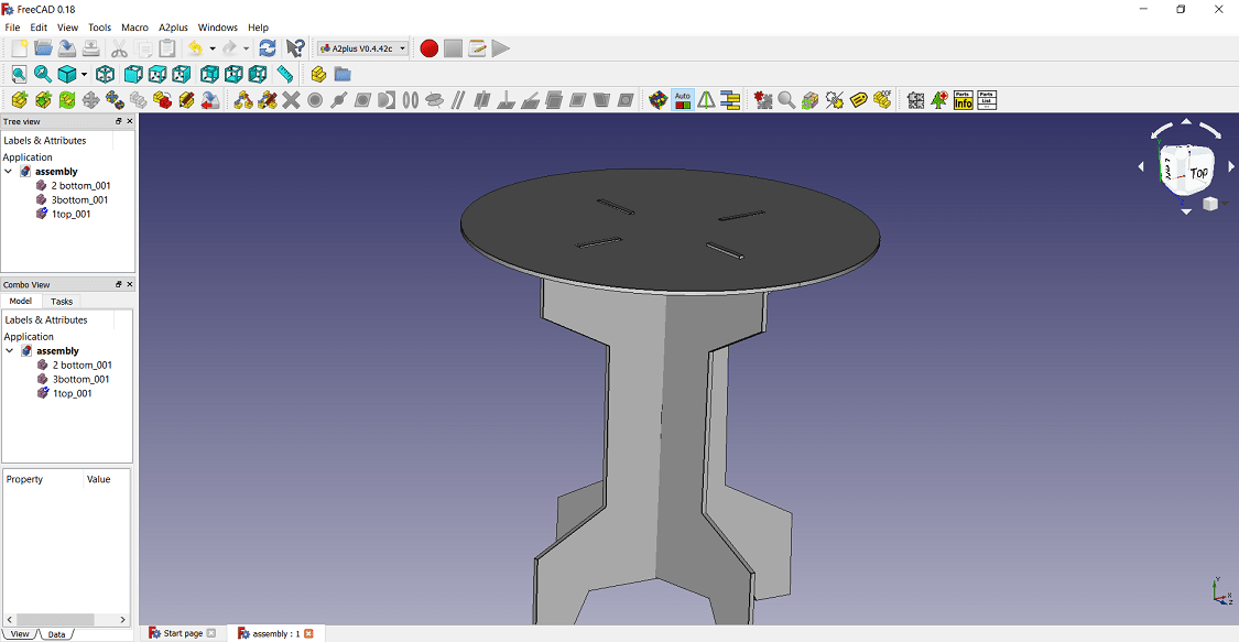
The final design of the model
CAM Machining
The CAM machining has three parts 1. Software 2. Machinery 3. Post Processing. For machining
here Part Design software is used to generate the toolpath, ShopBot Machine is used for plywood milling i.e. cutting. 3.ShopBot machine software is used for converts toolpaths into
a language machines can understand. so lets discuss one by one
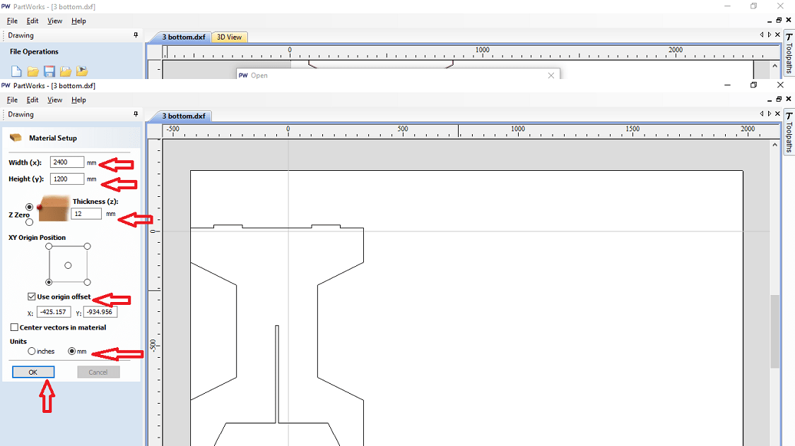
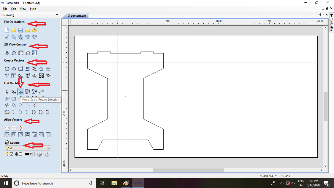
1. Software: The design is developed in FreeCAD software. The assembly of the object is exported as a .dxf file from the FreeCAD. Then this file is open in Part Design software. Here set the dimesion (x and y dimesion) of raw material i.e. sheet and thickness of material (z dimension)
Then press ok.
The move the object on the worktable, where we want to cut the sheet. Also the another option are given in software. Use that according to necessary.
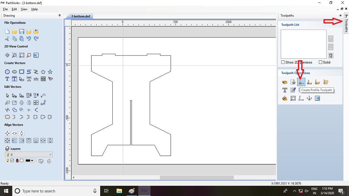
Then on the right side toolpath option is given so click on it and click on create the toolpath option.
Then such option is created. so select the cutting depth of the tool, here i am using 12 mm sheet, so set depth by 0.5 mm is extra, because in case plywood the thickness is not constant so here the cut depth is 12.5 mm.
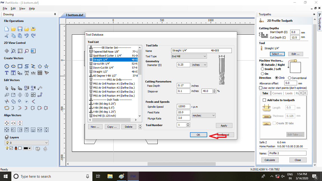
Select the tool, here we are using 1/4 inch tool. Then select the machine vector, it will decide the toolpath and then press calculate.
The chip load, Feed rate and speed are corelated like this:
Chip Load = Feed rate (IPM)/ (RPM x cutting edge)
Feed Rate (IPM) = RPM x # of cutting edges x Chip Load
Speed (RPM) = Feed Rate (IPM) / (# of cutting edges x Chip Load)
IPM = IPS x 60
Depth of cut: A function of cutting edge diameter set by manufacturer.
Meaning of abbrivation
Chip Load = per cutting edge.
IPS = Inches Per Second.
IPM = Inches Per Minute.
RPM = Revolutions Per Minute.
# of cutting edges = # of flutes.
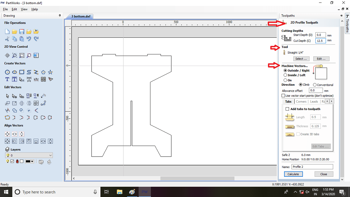
Machine setting for toolpath
1) 2D Profile toolpath
Start Depth (D)= 0.0 mm
Cut Depth (C) = 12.5 mm
2) Tool- straight 1/4"
Tool type - end mill
Diameter - 0.25"
3) Cutting Parameter
Pass depth - 0.17"
Step over - 0.1"(40%)
4) Feeds and Speeds
Spindle speeds = 12000 rpm
Feed rate = 22.0 mm/sec
Plunge rate = 3.0 mm/sec
Tool Number = 1
5) Machine vectors- Outside/Right
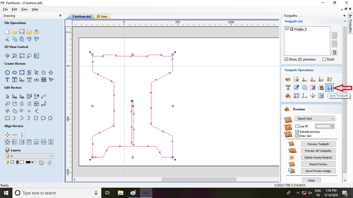
Such toolpath is generated and then save the toolpath
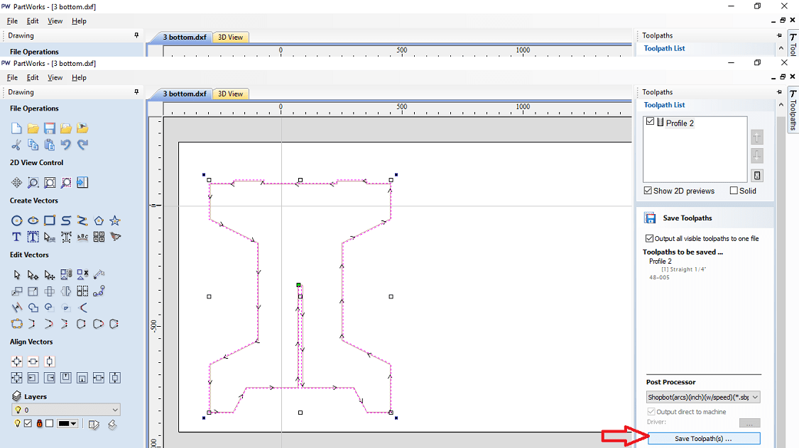
2. Post Processing- It is used for to converts the toolpaths into a language machines can understand. This is a machine software. For Shopboat machine, ShopBot is a CAM software.
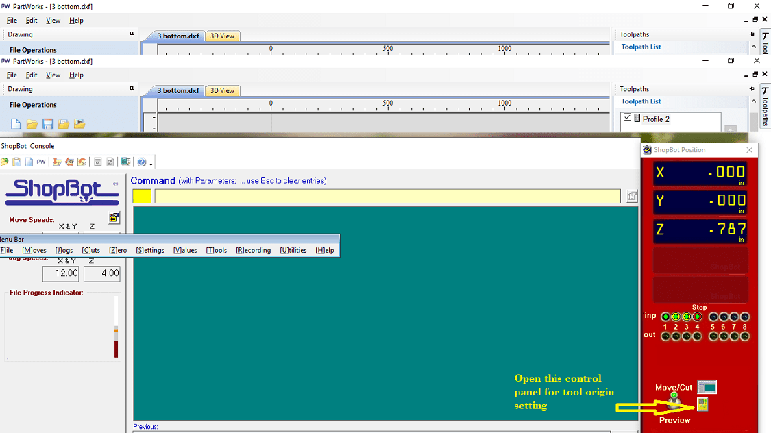
So after processing the design in Part Design software, then the design is loaded in ShopBot software. In this software, the machine origin is to be set and the machine is opertaed through the software also.
Firstly open the software. Open the control panel for X,Y & Z origin setting of tool.
Set the x,y,z origin of tool on machine table by using this tool. From the keypad also the machine is operated.
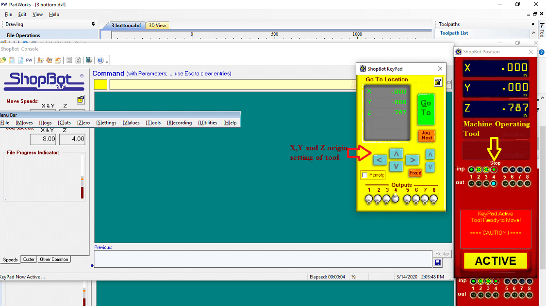
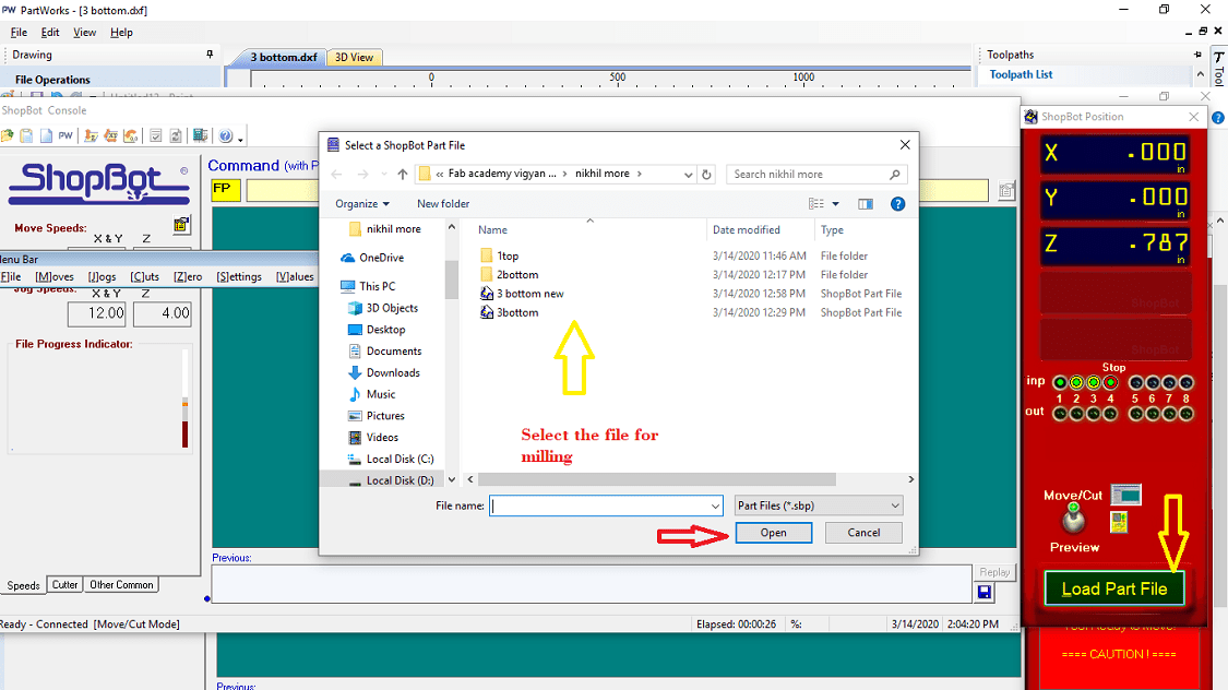
Then load the design file and start the milling operation.
3. Milling Operation- For cutting the plywood material, shopbot machine is used which is a milling machine. The Shopbot Machine of Fab Lab, COE Pune has following specification:
Sheet Material up to Size: 4 Feet x 8 Feet x 6 inch in x,y,z direction resp.
Table Size: 6 Feet x 10 Feet
Step Resolution : 0.0005 inch
Positioning Accuracy: +/- 0.0005 inch (No Load)
Cutting Accuracy: +/- 0.015 inch
Simultaneous linear interpolation: 3 Dimensional
X,Y and Z axis drive system: Rack and Pinion
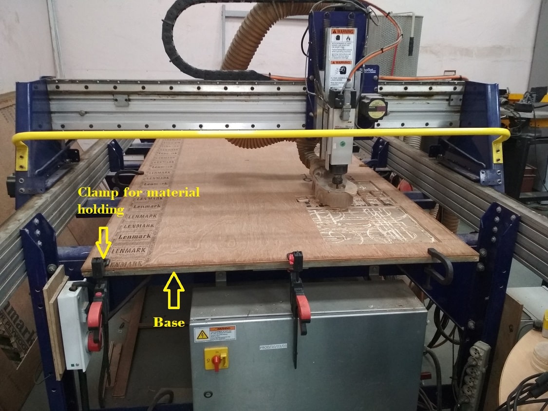
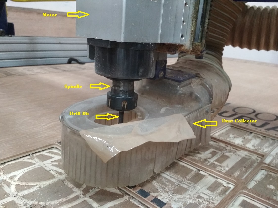
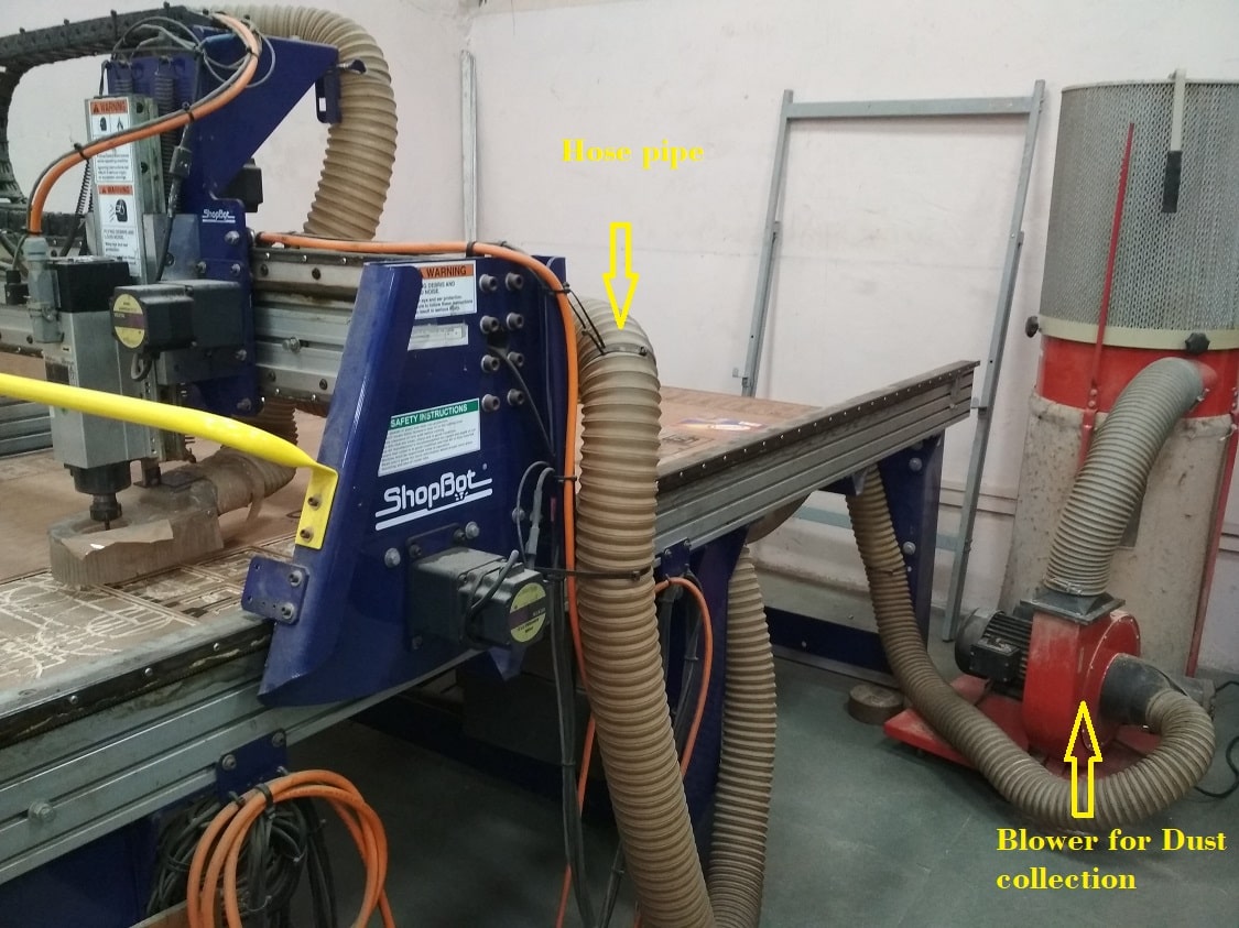
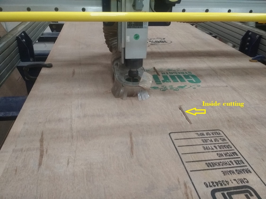
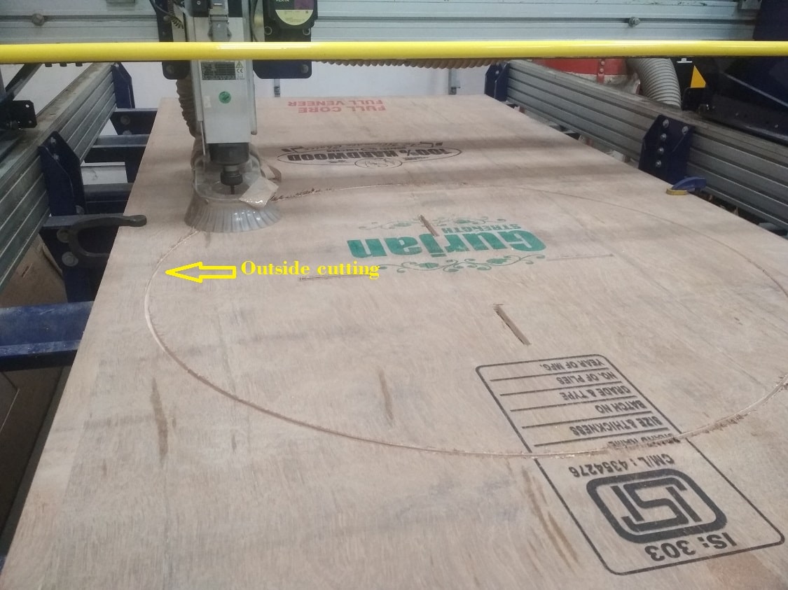
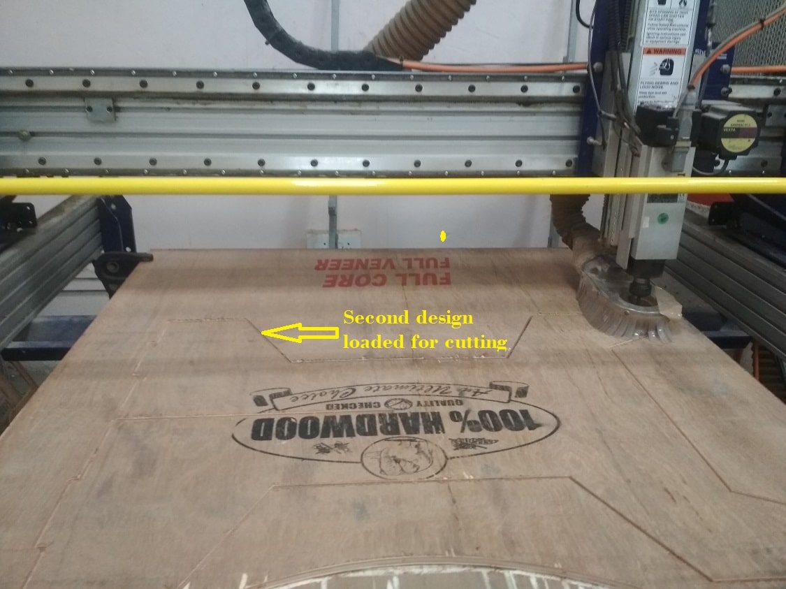
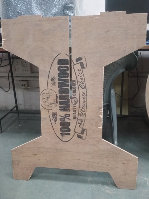
After loading the file in shopbot software, the cutting of the material will get start, before this machine gives some instructor,its need to follow it strickly. There is button for spindle start, so start the spindle before cutting. Now the cutting is start for inside design then we load the file for outside cutting. Always cut the inside material first and then the outside material. Similarly i loaded the next file. Belows are the some photos during milling.
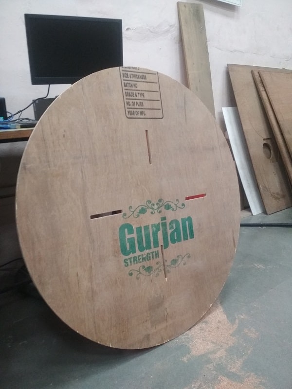
Assembly of Parts
After milling the different parts on shopbot machine, now the assembly of part is done by press fit method.
What i learn?
I am learn about
1. Parametric design using spreadsheet for big size furniture
2. Use of CAM software
3. Different parameter for CAM machining such as test runout, alignment, speeds, feeds and toolpaths
4. Operation and handling of Shopbot machine
5. Pressfit assembly of part
Go to the top
Back
Assignment 9: Embedded Programming
An Embedded System can be best described as a system which has both the hardware and software and is designed to do a specific task..

Fab Academy Course on Digital Fabrication by Nikhilkumar More is licensed under a Creative Commons Attribution-NonCommercial 4.0 International License.
Based on a work at http://fabacademy.org/2020/labs/vigyanashram/students/nikhilkumar-more/.
Permissions beyond the scope of this license may be available at http://fabacademy.org/2020/labs/vigyanashram/students/nikhilkumar-more//contact.html