Input Devices
During this assignment, I am at Home dut to COVID-19, so I am tried online simulation tool. When I have get lab access then I will try it on actual hardware.
Week Task
Individual assignment: measure something: add a sensor to a microcontroller board, that you have designed and read it
group assignment: probe an input device's analog levels and digital signals
Introduction
An input device responds to changes in the environment and produces a suitable electrical signal for processing in an electronic circuit.
In all input devices, other forms of energy are transformed into electrical energy.The sensor is an element that produces signals relating to the quantity that is being measured.
According to Instrument Society of America, “a sensor is a device that provides usable output in response to a specified quantity which is measured.” The word sensor is derived from the original
meaning ‘to perceive.’
Sensors are devices that perform input function in a system as they ‘sense’ the changes in a quantity. The best example of a sensor is mercury thermometer. Here the quantity that is being measured
is heat or temperature. The measured temperature is converted to a readable value on the calibrated glass tube, based on the expansion and contraction of liquid mercury.
Criteria to Choose a Sensor
The following are certain features that are considered when choosing a sensor.
Type of Sensing: The parameter that is being sensed like temperature or pressure.
Operating Principle: The principle of operation of the sensor.
Power Consumption: The power consumed by the sensor will play an important role in defining the total power of the system.
Accuracy: The accuracy of the sensor is a key factor in selecting a sensor.
Environmental Conditions: The conditions in which the sensor is being used will be a factor in choosing the quality of a sensor.
Cost: Depending on the cost of application, a low cost sensor or high cost sensor can be used.
Resolution and Range: The smallest value that can be sensed and the limit of measurement are important.
Calibration and Repeatability: Change of values with time and ability to repeat measurements under similar conditions.
A Brief Introduction to Smoke Sensor
There are two types of smoke detectors. Optical or Photoelectric smoke detectors and Ionization smoke detectors.
Optical smoke detectors consists of a light source like LED and a light detector like photocell.
The photocell conducts as long as the light falls on it. When there is smoke, the light from the source is interrupted and the photocell doesn’t conduct.
Ionization smoke detectors consists of two electrodes and an ionization chamber filled with ions. When there is no smoke, the ions move freely and the electrodes conduct normally.
In the presence of smoke, the chamber is filled with smoke and interrupts the movement of ions. The electrodes do not conduct anymore. Depending on the type of sensor and manufacturer, the conductivity conditions may change but the idea remains the same.
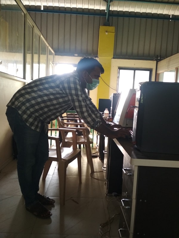
Individual Assignment
The task for the week is to measure something: add a sensor to a microcontroller board, that we have designed and read it. Here in India, the Govt. of India is announced the Lockdown of 21 days. As per the schedule of Fab Academy, the assignment number 8,9 & 10 is between this period. I am at home, so i dont have lab acessed for this assignment right now. So i am trying to connect the sensor on arduino board on TinkerCad software and read it using serial monitor.Here i am trying three different sensor in TinkerCad 1. Smoke sensor 2. PIR (motion) sensor 3. Light Sensor. In my final project i am using smoke sensor. so i have develop the board for the smoke sensor module using ATtiny 44 IC in Eagle software. When i went to lab, then i will develop the board on milling machine and assembling the all components and in an actual i will read the data.
Group Assignment
The task for the week is to probe an input device's analog levels and digital signals. For analog levels we use temperature sensor and for digital levels we use ultrasonic sensor.The sensor is connected with oscilioscope for signal levels. For more details about group task click here
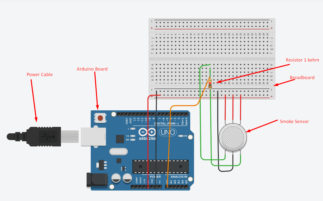
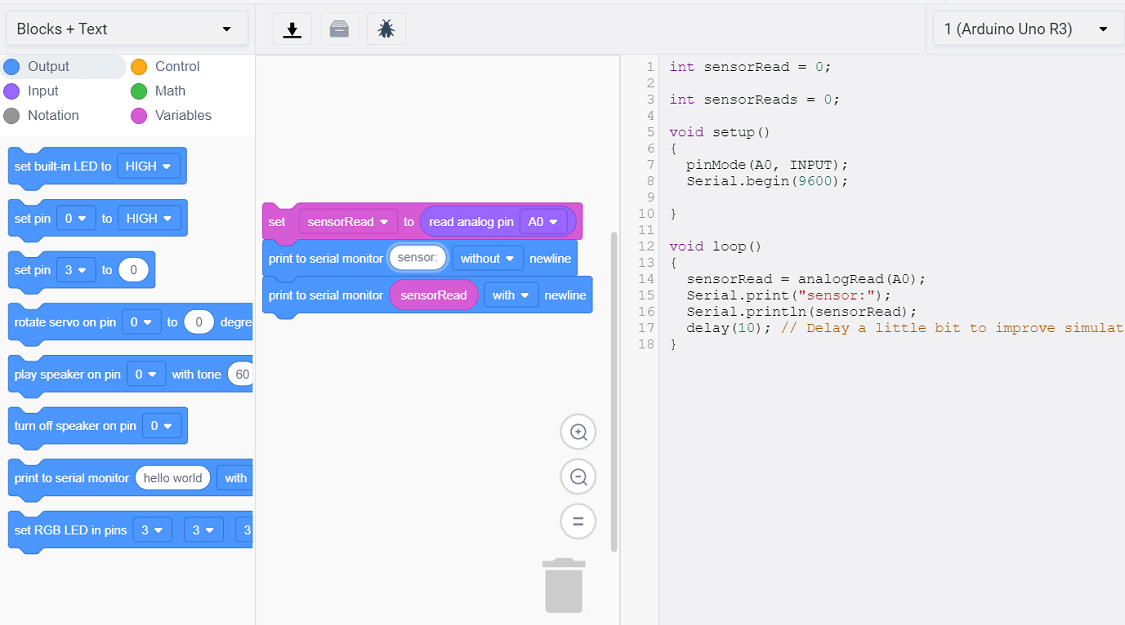
Smoke Sensor with Arduino Board
The smoke sensor is connected to Arduino board. The sensor has 6 pin on two side. 3 pin from one side is connnected to power. From other side, one pin is connected GND and two are signal pin. One is analog signal and other is digital signal. Analog pin is connected to A0 analog port on Arduino board.
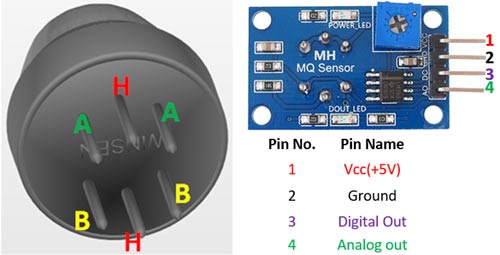
H -Pins: Out of the two H pins, one pin is connected to supply and the other to ground.
A-Pins: The A pins and B pins are interchangeable. These pins will be tied to the Supply voltage.
B-Pins: The A pins and B pins are interchangeable. One pin will act as output while the other will be pulled to ground.
The code is generated for the sensor using the command. The reading of the sensor is printed on the serial monitor.
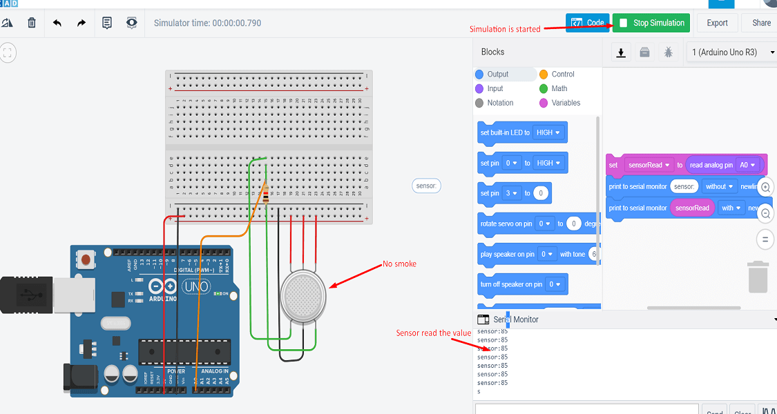
Then start the simulation. The reading of the sensor without smoke is shown.
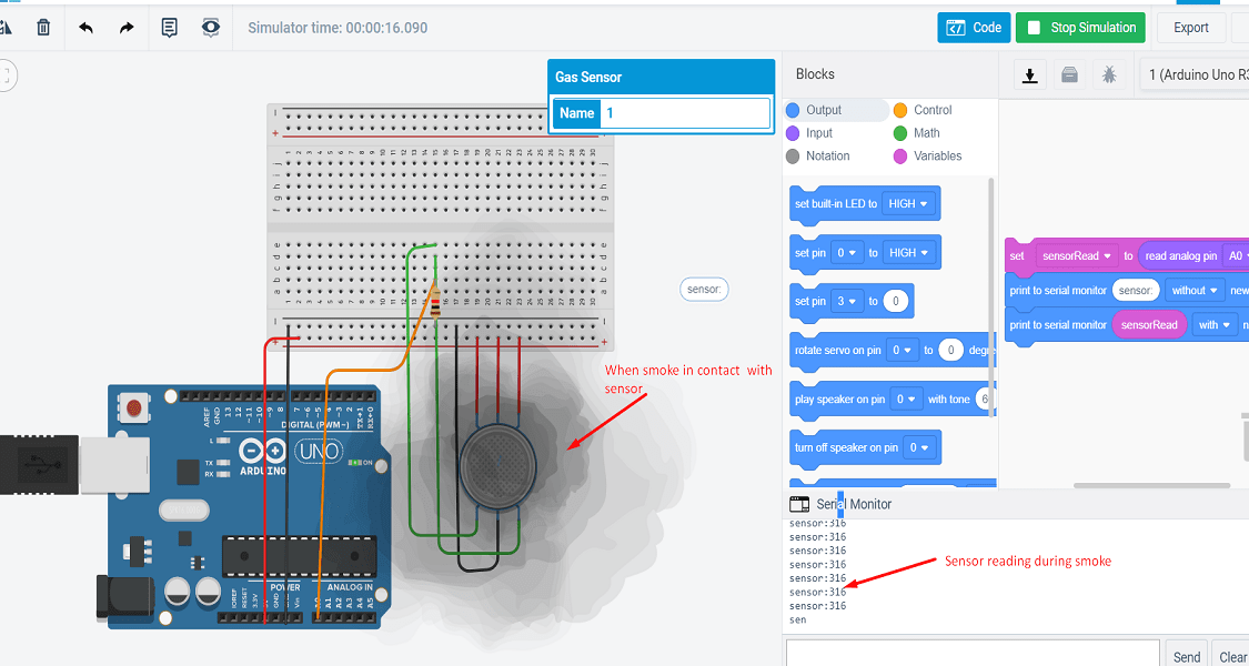
The reading of the sensor when high intensity smoke is in contact with the sensor.
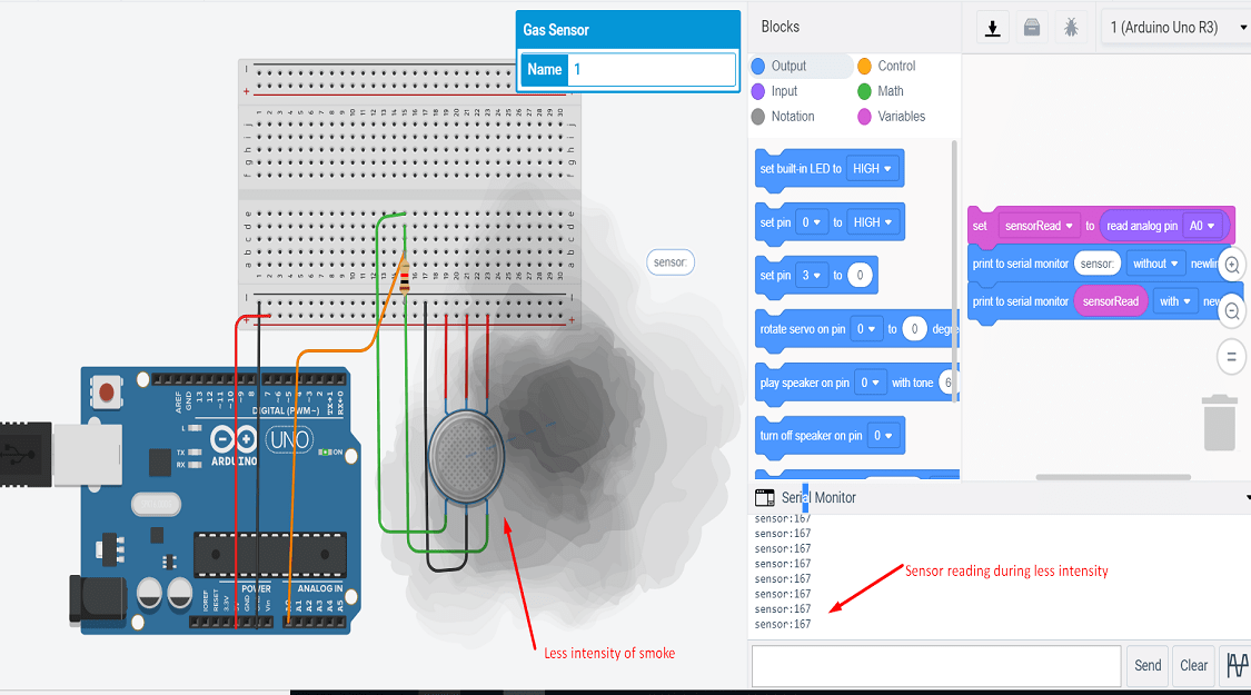
The reading of the sensor when less intensity smoke is in contact with the sensor.
Here is the video of connection and simulation.
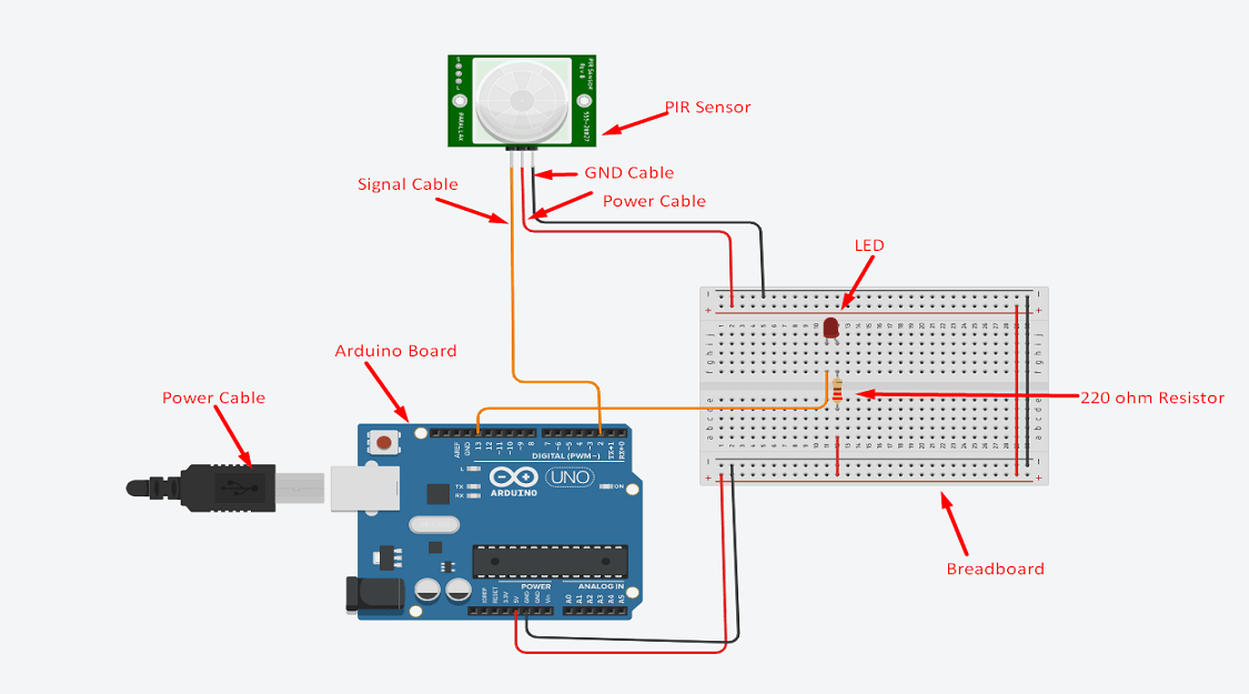
PIR Sensor with Arduino Board
A passive infrared sensor (PIR sensor) is an electronic sensor that measures infrared (IR) light radiating from objects in its field of view. They are most often used in PIR-based motion detectors. PIR sensors are commonly used in security alarms and automatic lighting applications.
PIR sensors detect general movement, but do not give information on who or what moved. For that purpose, an active IR sensor is required.
PIR sensors are commonly called simply "PIR", or sometimes "PID", for "passive infrared detector". The term passive refers to the fact that PIR devices do not radiate energy for detection purposes.
They work entirely by detecting infrared radiation (radiant heat) emitted by or reflected from objects.
There are the 3 pins are given to sensor. One is power, second is ground and third is signal. LED is also connected to
the board. When the object is detected, the LED will blink.
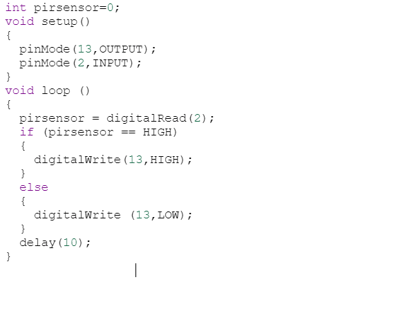
The code for LED blinking when the object is detected is as follows.
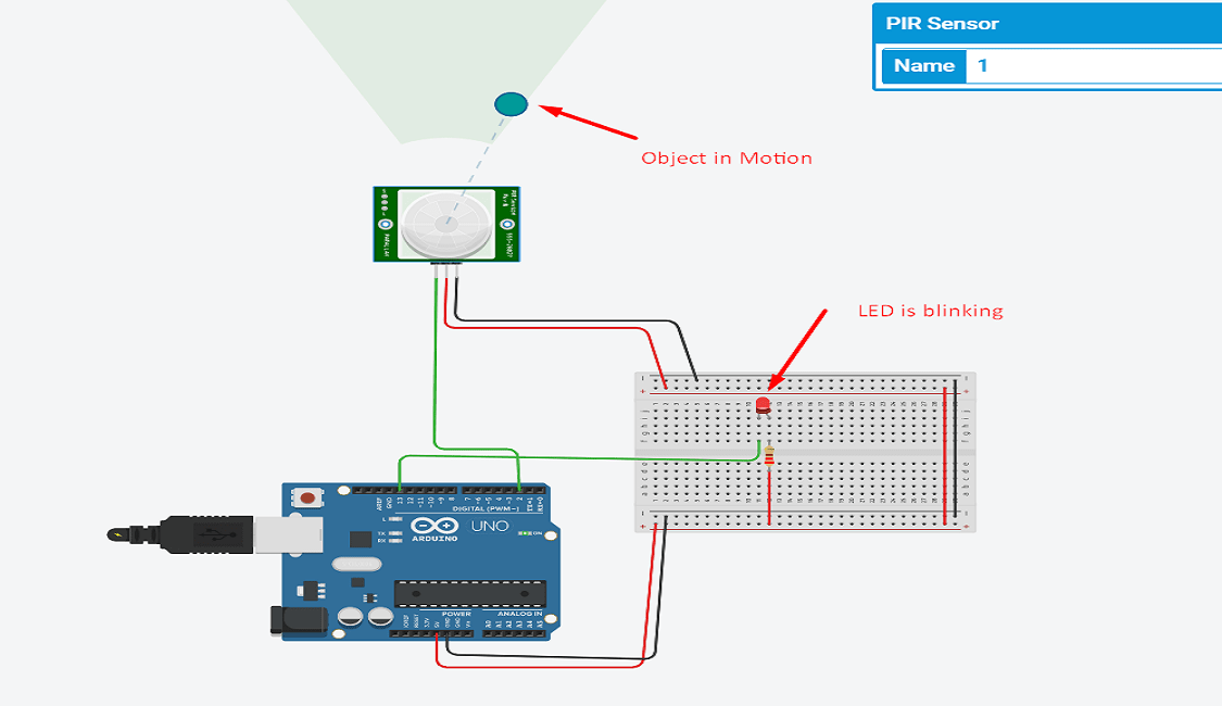
Now start the simulation. The LED is blinking here wuth the motion of the object is detected by the sensor.
Here is the video of connection and simulation.
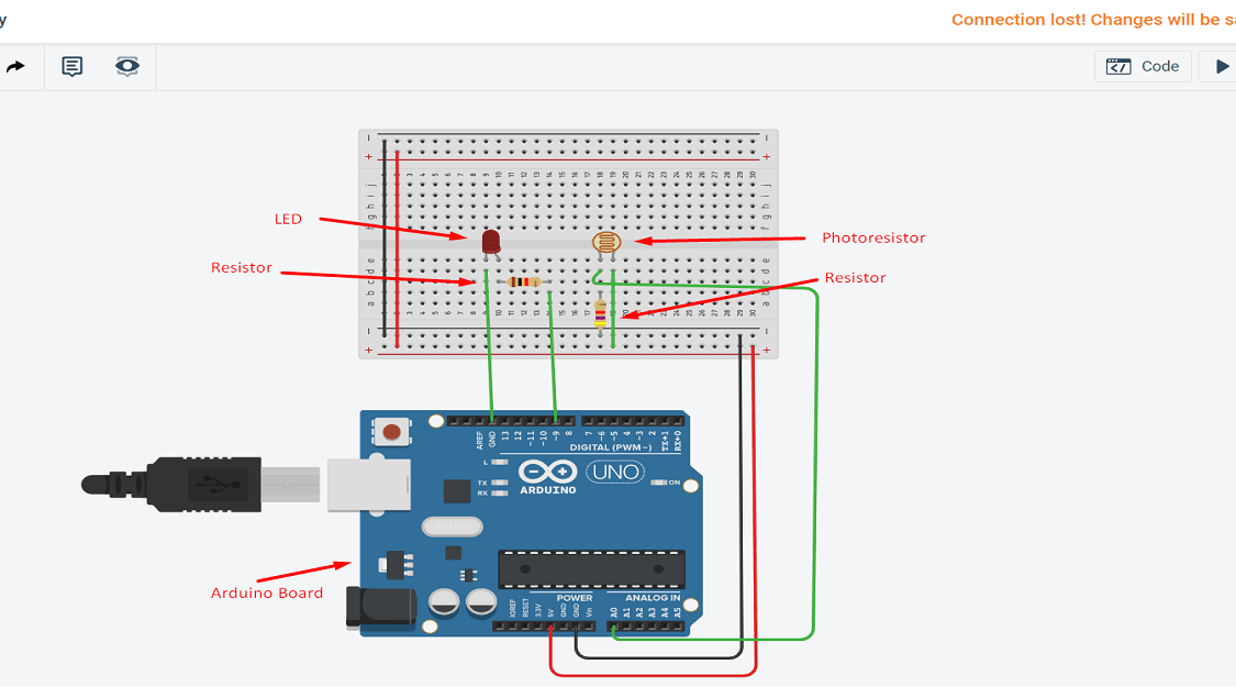
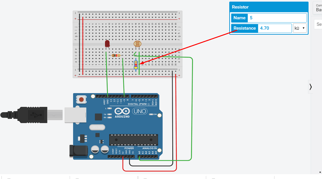
Light Sensor with Arduino Board
The light sensor is a passive devices that convert this “light energy” whether visible or in the infra-red parts of the spectrum into an electrical signal output.
Light sensors are more commonly known as “Photoelectric Devices” or “Photo Sensors” because the convert light energy (photons) into electricity (electrons).
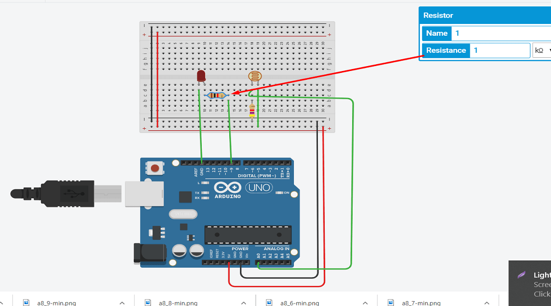
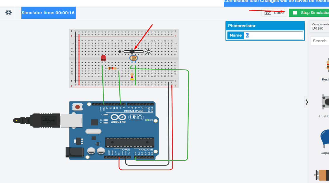
Here the photoresistor sensor is connected to the Arduino board.
The value for the resistor is as follows.
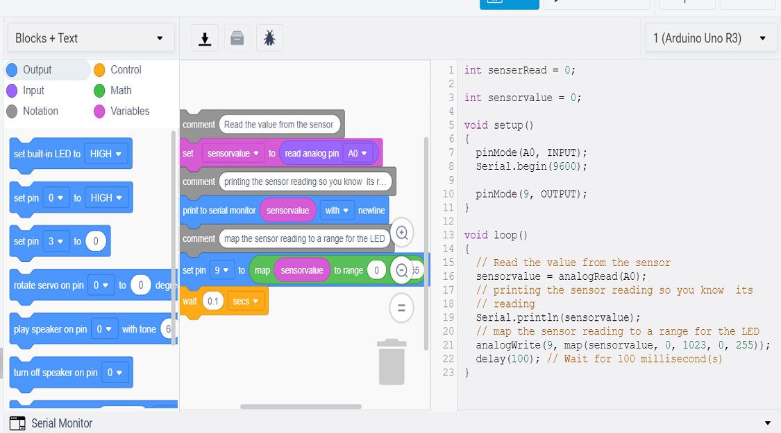
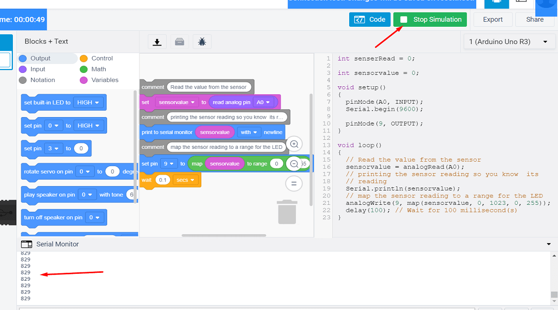
The code is generated using the command in software. The reading of the sensor is displayed on the serial monitor.
Now the simulation is start. The reading of the sensor is displayed on serial monitor when there is no light.
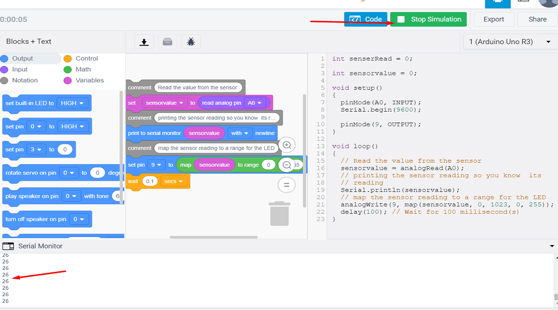
As the intensity of the light is change, the reading for the sensor will get change.
Here is the video of connection and simulation.
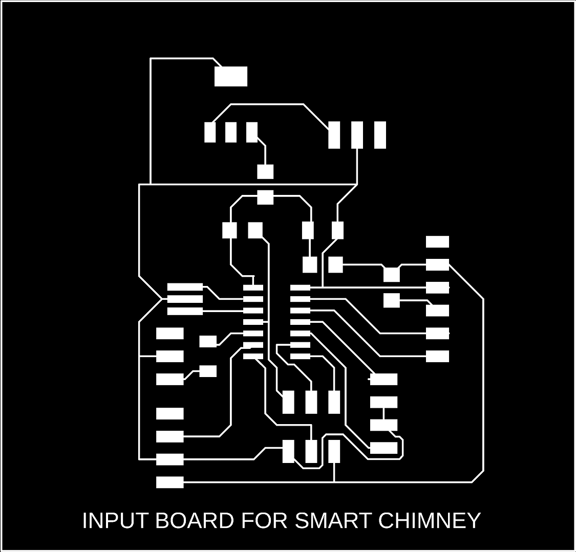
Design of Smoke Sensor Board
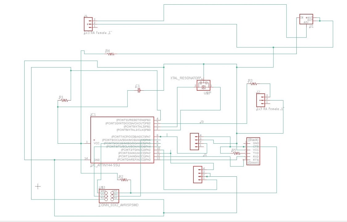
For final project, i have required smoke sensor, to sense the smoke get exhausted from the burning of fuel in kitchen for cooking. When the sensor sense the smoke, it will gives signal to the microcontroller and fan of the chimeny will get start. The smoke from the kitchen will get exhausted to the outside. So here i am trying to develope the board of smoke sensor. I am using smoke sensor module, so the 4 pins are provided on the board to connecte the module. ATtiny 44 IC is used for the board. The Eagle software is used to design the board.The connection of the in Eagle software is as belows. The schematic of the PCB is as follows:
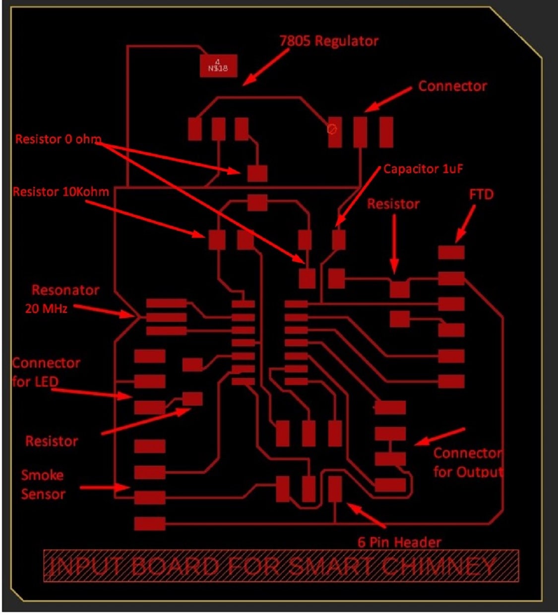
The final board design with its components used are shown below.
Now I am went to the lab from 22 June and start working on the project work. Firstly I am milling this input board on SRM-20 milling machine. The design of the board from the eagle software firstly exported as a png file. The this png file is converted into rml file using fab mods (details about this procedure is given in my assignment 5 and 7). Then the rml is loaded to the machine for trace and cut the PCB.