Embedded Programming
During this assignment, I am at Home dut to COVID-19, so I am tried online simulation tool. When I have get lab access then I will try it on actual hardware.
Week Task
Individual assignment: read a microcontroller data sheet, program your board to do something,
with as many different programming languages and programming environments as possible
Group assignment:
compare the performance and development workflows for other architecture
Introduction
An Embedded System can be best described as a system which has both the hardware and software and is designed to do a specific task. The Processor is the heart of the Embedded System and it can be anything like a Microprocessor, Microcontroller, DSP, CPLD (Complex Programmable Logic Device) and FPGA (Field Programmable Gated Array). All these devices have one thing in common: they are programmable i.e. we can write a program (which is the software part of the Embedded System) to define how the device actually works.

Embedded Software or Program allow Hardware to monitor external events (Inputs) and control external devices (Outputs) accordingly. During this process, the program for an Embedded System may have to directly manipulate the internal architecture of the Embedded Hardware (usually the processor) such as Timers, Serial Communications Interface, Interrupt Handling, and I/O Ports etc. There are many programming languages that are used for Embedded Systems. In the process of making a better embedded system, the programming of the system plays a vital role and hence, the selection of the Programming Language is very important. In this assignment, we trying to develop the code using different languages and environments.
What is a Micro-controller?
A microcontroller is a small, low-cost and self contained computer-on-a-chip that can be used as an embedded system. A few microcontrollers may utilize four-bit expressions and work at clock rate frequencies, which usually include:
An 8 or 16 bit microprocessor.
A little measure of RAM.
Programmable ROM and flash memory.
Parallel and serial I/O.
Timers and signal generators.
Analog to Digital and Digital to Analog conversion
Microcontrollers usually must have low-power requirements since many devices they control are battery-operated. Microcontrollers are used in many consumer electronics, car engines, computer peripherals and test or measurement equipment. And these are well suited for long lasting battery applications.
The dominant part of microcontrollers being used now a days are implanted in other apparatus.
Types of Micro-controller
The microcontrollers are characterized regarding bus-width, instruction set, and memory structure.
For the same family, there may be different forms with different sources. Following are the some basic families of microcontroller
LOGIC
Megaprocessor
8051
PIC
MSP
AVR
ATtiny412, ATtiny45V,
ATtiny1614, ATtiny44A,
ATtiny3216,
ARM
D11C, D11D,
D21E,
D51
Xtensa
ESP8266
ESP32
RISC-V
PSoC
xCORE
Propeller
Lattice
NVIDIA
Difference between Micro-controller and Micro-processor
Microprocessor is an IC which has only the CPU inside them i.e. only the processing powers such as Intel’s Pentium 1,2,3,4, core 2 duo, i3, i5 etc. These microprocessors don’t have RAM, ROM, and
other peripheral on the chip.
A system designer has to add them externally to make them functional. Application of microprocessor includes Desktop PC’s, Laptops, notepads etc.
Microcontroller has a CPU, in addition with a fixed amount of RAM, ROM and other peripherals all embedded on a single chip. At times it is also termed as a mini computer or a computer on a
single chip. Microcontrollers are designed to perform specific tasks. Specific means applications where the relationship of input and output is defined. Depending on the input, some processing needs to be done and output is delivered. For example, keyboards, mouse, washing machine,
digicam, pendrive, remote, microwave, cars, bikes, telephone, mobiles, watches, etc. Since the applications are very specific,
they need small resources like RAM, ROM, I/O ports etc and hence can be embedded on a single chip. This in turn reduces the size and the cost.
AVR Micro-controller
AVR microcontroller is an electronic chip manufactured by Atmel, which has several advantages over other types of microcontroller.
AVR microcontroller comes in different configuration, some designed using surface mounting and some designed using hole mounting. It is available with 8-pins to 100-pins, any microcontroller with 64-pin or over is surface mount only.
AVRs are generally classified into following:
tinyAVR – the ATtiny series
megaAVR – the ATmega series
XMEGA – the ATxmega series.
Group Assignment
The task for the week is to compare the performance and development workflows for other architecture. Here we comapre the three board ATMEGA 328P, ESP 32 and Rasberry Pi 3. For more details click here
Individual Assignment
The task for the week in individual assignment is to read a microcontroller data sheet, program your board to do something, with as many different programming languages and programming environments as possible. So here on my board I am using ATtiny44A IC, so I have read the datasheet of this microcontroller. This is week somewhat typical to me, because I dont know anything about programming and its different languages. The simulation I have tried on TinkerCAD simulation software and then I will trying it on microcontroller board.
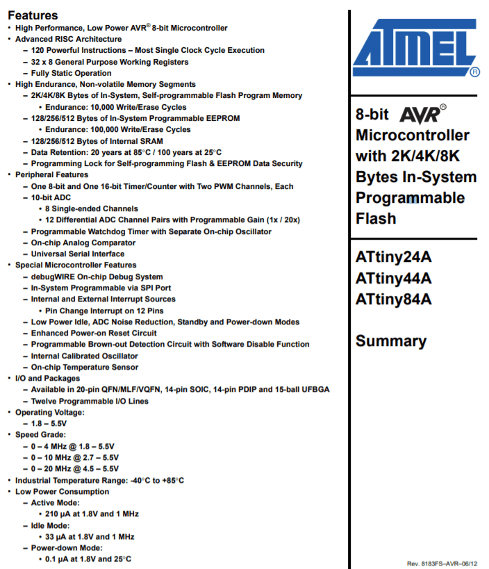
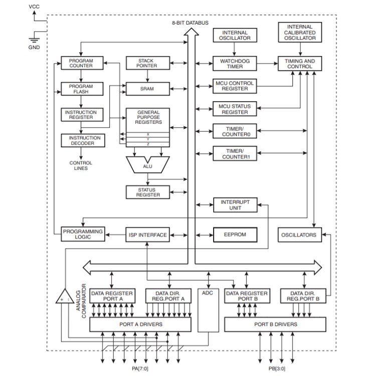
Datasheet of ATtiny44A
First page of the datasheet, shows the feature of this microcontroller.
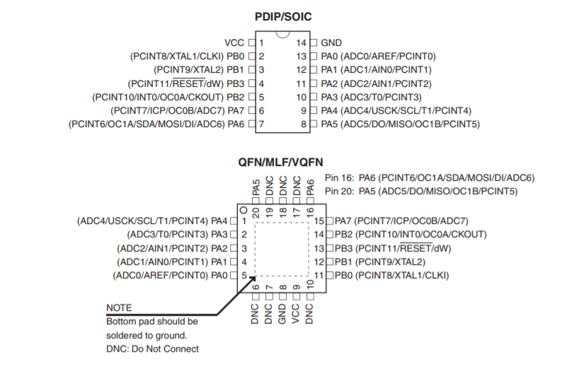
The I have read the pin configuration, here the ATtiny44A has 14 pin, where 1pin for VCC and 1 pin for GND, A port has 8 pin and B port has 4 pin, all is the I/O pin.
The block diagram of ATtiny44A .
Different languages for Embedded Programming
The list showing the 15 best embedded programming languages
1. C
2. C++
3. Java
4. Python
5. Rust
6. Ada
7. JavaScript
8. Go
9. Lua
10. B#
11. Assembly Language
12. C#
13. Verilog
14. VHDL
15. Embedded C++
Different IDE used for Embedded Programming
Following are the mostly used IDE for Embedded Programming
1. Atmel Studio
2. Arduino
3. Eclipse AVR
4. Fireflybr
5. Scratch
6. Modkit
Arduino Board Programming using C++ Language
Arduino code is written in C++ with an addition of special methods and functions, which we’ll mention later on. C++ is a human-readable programming language. When you create a ‘sketch’ (the name given to Arduino code files),
it is processed and compiled to machine language.The Arduino Integrated Development Environment (IDE) is the main text editing program used for Arduino programming. It is where you’ll be typing up your code before uploading it to the board you want to program. Arduino
code is referred to as sketches. Here i used the Tinkercard software for learning this language and its simulation. The Tinkercard is a Autodesk free software which is used for Simulation and programming Arduino and breadboard components.
It will use standard modules to build complex circuits. Firstly i used the blink programm with different high and low time.
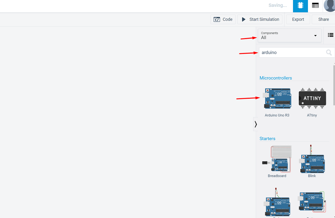
Open the Tinkercard software. In the right side, search the components that we required in circuits. Drag it on the screen
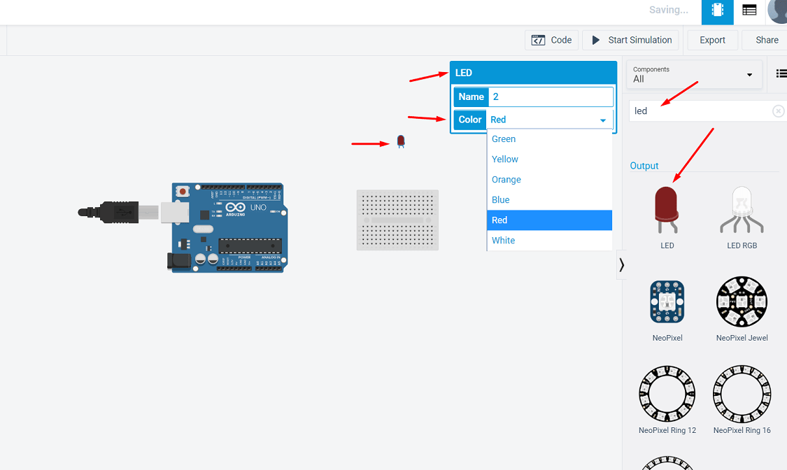
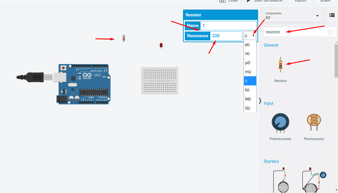
Simillarly searched the other components, we can change the specification of the components, In case of LED, the diffrent colors are given for LED and in case resistor we can changen the value of resistence with unit also.
Now open the code, use the different command for LED blinking. Here we use 13 number pin for connection and time of blinking and delay is 1 sec.
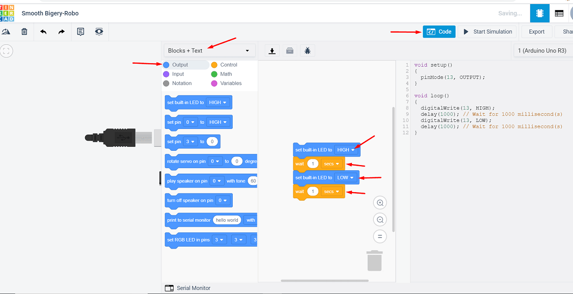
I have sharing the video of simulation of this programm. I have changing the time in code and observe the changes.
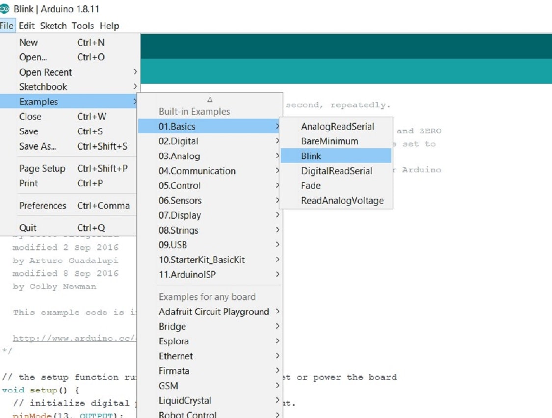
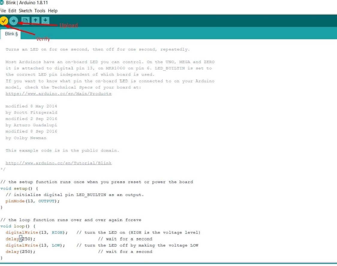
In an actual, I am trying this, for this prupose I have downloaded the Arduino IDE in my laptop, open it, then in click on file menu>expample>basic>blink. The blink programm will get open.
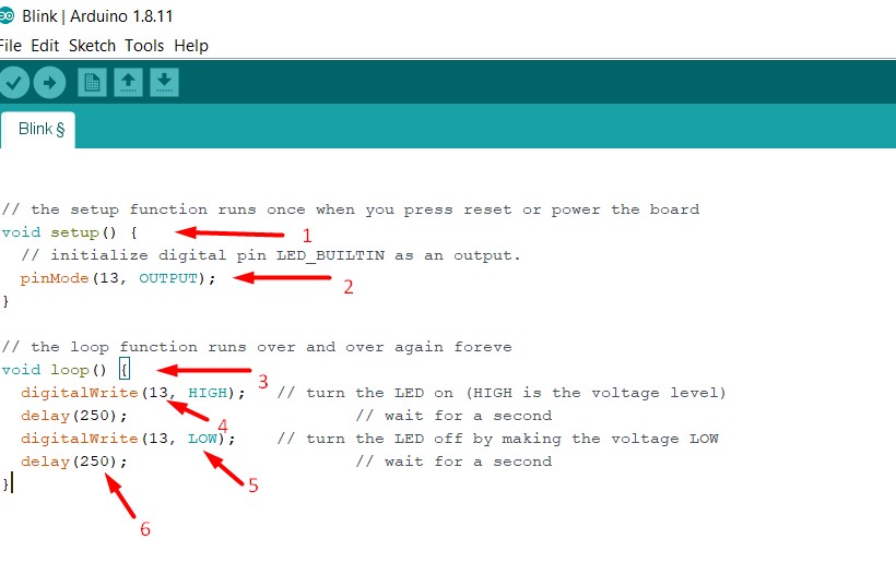
1. void setup()- It has a block of statements written inside parentheses. Here setup() is a function in APL (arduino programming language) used to declare configuration statements for the micro controller ports.
While playing with a micro controller, we need to configure different micro controller ports as INPUT source or OUTPUT.
2. pinMode (13, OUTPUT);- In this project we are going to blink an LED at port number 13 of micro controller. To blink an LED means, we have to turn it ON and OFF alternatively at a certain interval. So we are going to send commands to turn LED ON and OFF to port 13
of micro controller (arduino board). To do so, we have to configure port 13 as OUTPUT in our program. This is achieved inside the void setup() block.
3. void loop () - The next block begins with void loop() – here loop() is another predefined function in arduino programming language (APL).loop() is a function that indefinitely executes statements written inside its parentheses. This function enables the micro controller
(or arduino board) to do a set of actions as long as it is ON. In our case, those actions are turn LED ON and OFF at certain time intervals. So here is how we are going to tell arduino board to do the ON and OFF process.
4. digitalWrite(13, HIGH); – which is an instruction to write some data to a particular micro controller port in arduino board. We have connected LED to pin 13. To turn it ON, we have to supply a voltage at pin 13. We are going to do that via software commands.
Since our arduino board is connected to PC via USB, a +5 volts readily available. We need to pass this voltage to port 13 of arduino board. To do so, APL has a keyword
instruction called HIGH. So we just need to write an instruction digitalWrite(LED,HIGH); and this instruction when executed by micro controller will supply a +5 volts at port 13. This voltage will power LED and it will turn ON.
5. digitalWrite(13,LOW); - Now we need to turn LED OFF. We just need to disconnect the voltage supply given at port 13. This command will cut off supply at port 13 and LED will get OFF.
6. delay (250); - It is a setting a time interval in between ON and OFF time. The time given for delay is in Milli Seconds.
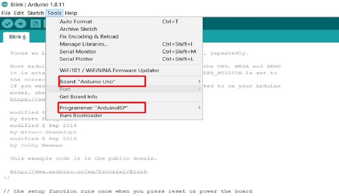
Then connection is done using Arduino Uno board and breadboard as per the above schematic>then click on tool>selcted the arduino uno board>programmer
There are two steps involved in loading the program from your PC to arduino board via the arduino IDE. First step is compiling and second step is called burning. Let’s see in detail.
STEP 1:- Compiling – This is the process of converting the code what we have written in arduino IDE to another form which is only understood by the micro controller in our arduino board. Here, we use arduino uno board.
It is made using Avr micro controller (Atmega328). In the arduino IDE, compiling is called as “verify“.
STEP 2:- Burning – The word “burning” to refer to uploading a program to any micro controller. So in this step, we are going to upload the verified program in arduino IDE to the arduino board. To do this, press the “upload” button (see the button with right arrow mark).
A click on the “upload” button will begin the process of burning the compiled program to Avr micro controller on our arduino board. Depending on the size of our program, this will take a little time. If we look on our arduino board, we can see the 2 LED’s near Tx and Rx blinking.
This is an indication of successful communication between your PC and arduino board. If the program has been uploaded successfully, we will see a message like “Done Uploading“.
If the uploading process was not successful, you will see an error message accordingl.
LED will get start to blink. This is the result
C Language Programming using Arduino IDE
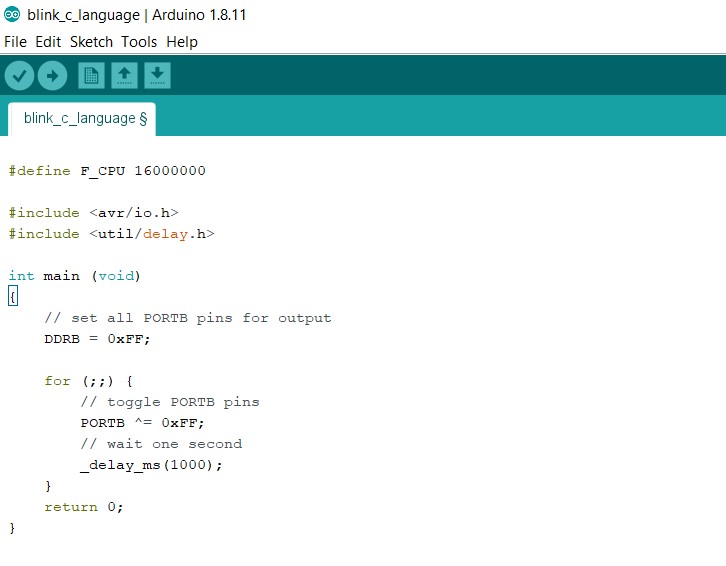
Now I am using C language for the LED blinking on ATTINY 44 Micro-controller board which I have develope in assignment 7. The objective of the work is to learn the command use in C-language. The programm is as follows:
Discussion about the command used in above code
1. #define F_CPU 16000000: This command defining clock speed of the processor.
2. #include < avr/io. h > : This header file includes the apropriate IO definitions for the device. Included are definitions of the IO register set and their respective bit values as specified in the Atmel documentation.
3. #include
4. int main (void) : It is the beginning of a function definition. Inside the curly braces that follow it, there are statements that are executed when your program runs.
"main" is the first function that will be called when you run your program."int" is the data type of the return value of the function. "(void)" is the list of parameters that main is expecting from its caller
5. DDRB = 0xFF; - DDRB is the Data Direction register for port “B”. This means that if you set this register to 0xFF (by running DDRB |= 0xFF ), all ports or pins in the “B” I/O port act as outputs.
6. PORTB ^= 0xFF; - The comment he gives for the PORTB = 0xFF line is to enable pull-up on input port.
7. delay_ms(1000); - This function is used generate delay during blink. It generates a delay of 1s for each count.
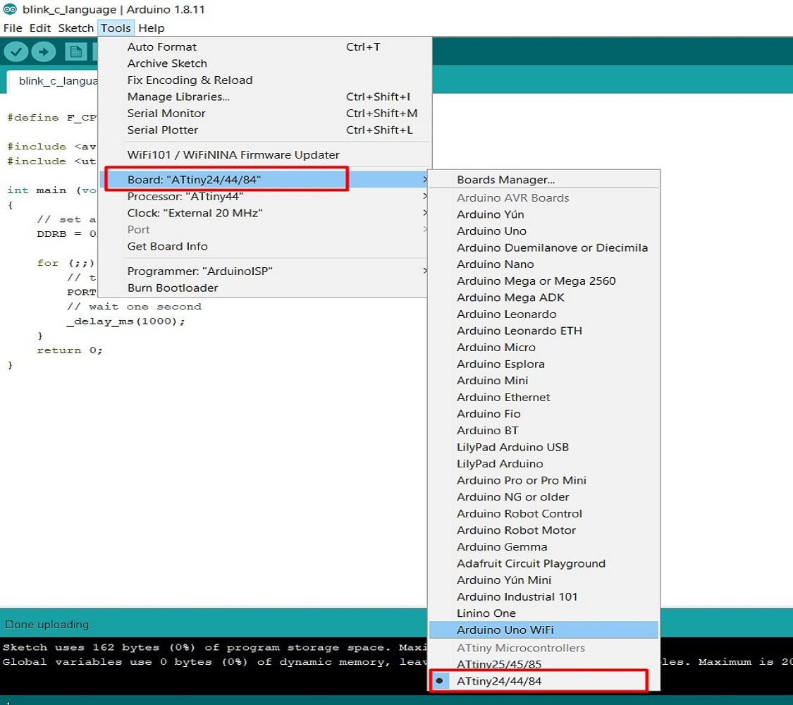
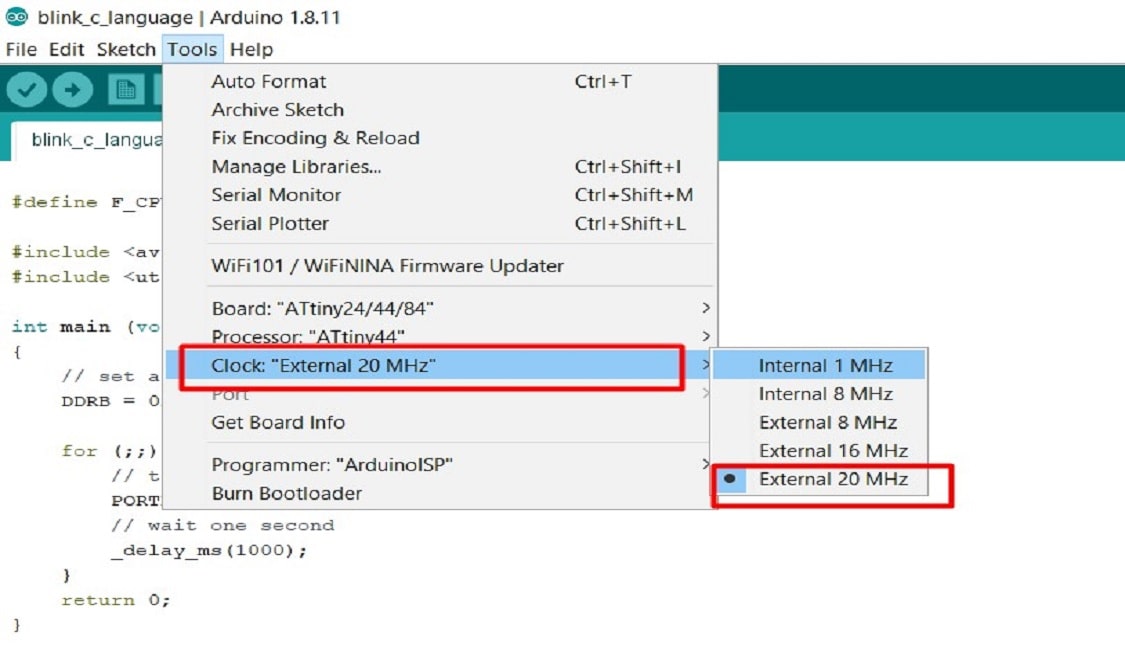
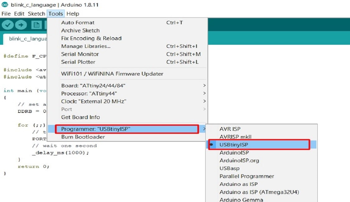
Firstly I have click on Tool menu and then selected the following four option
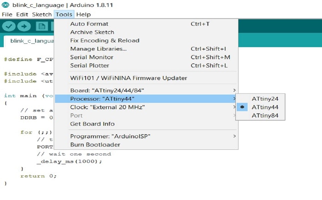
Now I have click on the verify button for compiling and the upload the code in the board. The following video shows the result
C Language Programming using Git Bash
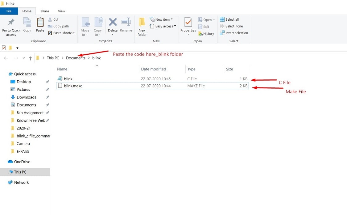
The another C-language programm of LED Blinking I have tried to upload in ATTINY 44 Micro-controller board using the command line.The code consists of two files. First is the .make file. The make file determines the file for the c code, the used microcontroller type, the frequency of the CPU and other project parameters.The second file is the .c file that has the code itself. This two file I have put in same folder name blink and it will be at document.
Refer this png file for programming the board.
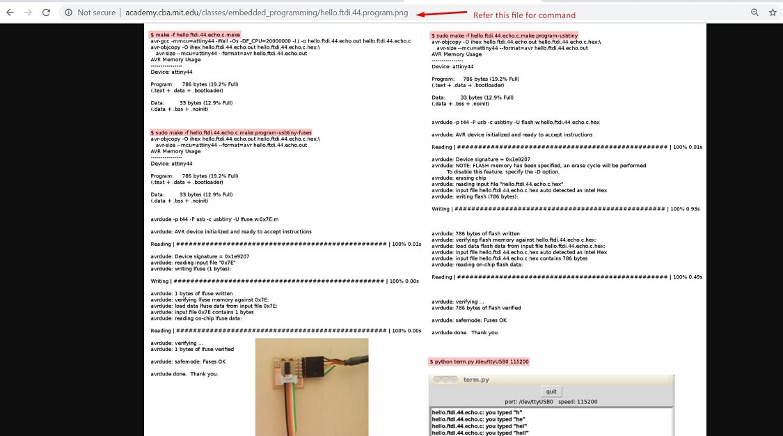
Then open the git bash in the same folder(Under Blink folder>right click>Git Bash here). Puting the first command for crating the .hex file from c file.
$make -f blink.make
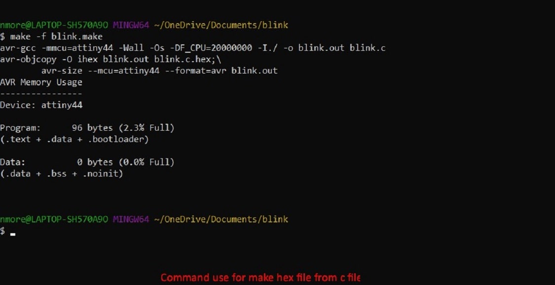
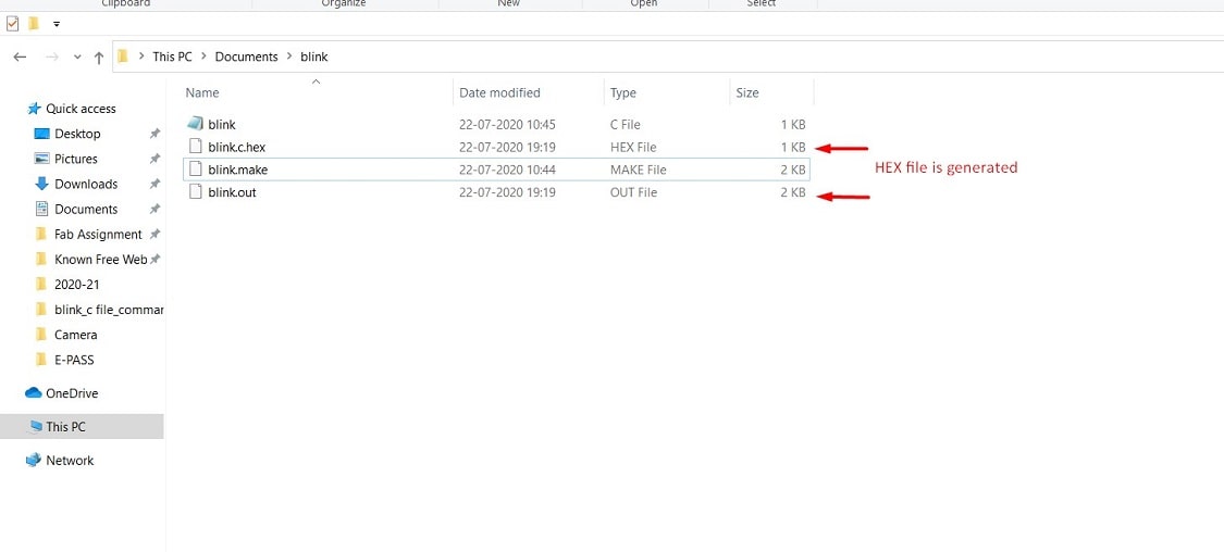
.hex file will get generate now in the same folder.
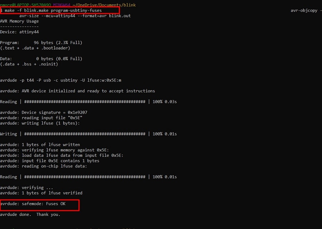
The putting next command for fuses the usbtiny. The command is
$ make -f blink.make program-usbtiny-fuses
The putting the last command for programming. The command is
$ make -f blink.make program-usbtiny
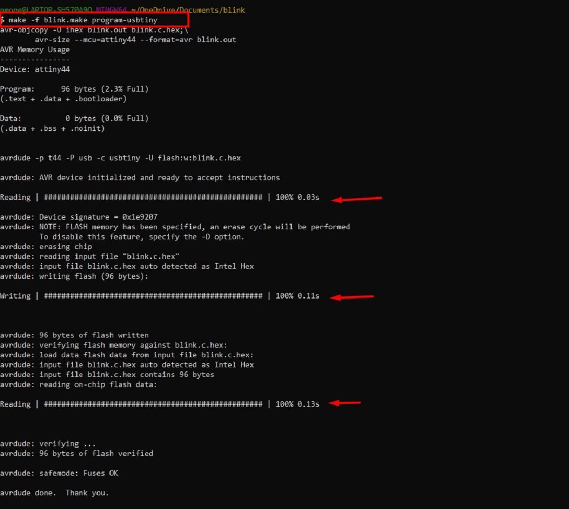
The programm is uploaded successfully in the board and LED will blinking. Lets see the video.