Computer Aided Design
Week Task
model (raster, vector, 2D, 3D, render, animate, simulate, ...) a possible final project, compress your images and videos, and post it on your class page
Introduction
CAD (Computer Aided Design) is the use of computer software to design and document a product’s design process. Engineering drawing entails the use of graphical symbols such as points, lines, curves, planes and shapes. Essentially, it gives detailed description about any component in a graphical form.
• CAD is used to accomplish preliminary design and layouts, design details and calculations, creating 3-D models, creating and releasing drawings, as well as interfacing with analysis, marketing, manufacturing, and end-user personnel.
CAD software enables
• Efficiency in the quality of design
•Increase in the Engineer’s productivity
•Improve record keeping through better documentation and communication
Types of CAD Software
CAD or Computer Aided Design software was introduced in the late 1960's to expedite engineering drawing process. While CAD is used mainly in engineering drawing and construction architecture, it can also used for other purposes.
There are various flavours of CAD available today and there are different methods of classifying them.
• Raster 2D Design
• Vector 2D Design
• 3D Design
• Animation
• Rendering, Simulation
Raster 2D Design
It is a dot matrix data structure which represent reactangular grid of pixels. Ratser image save in image file with different format. To draw the raster 2D design I have used KRITA and GIMP
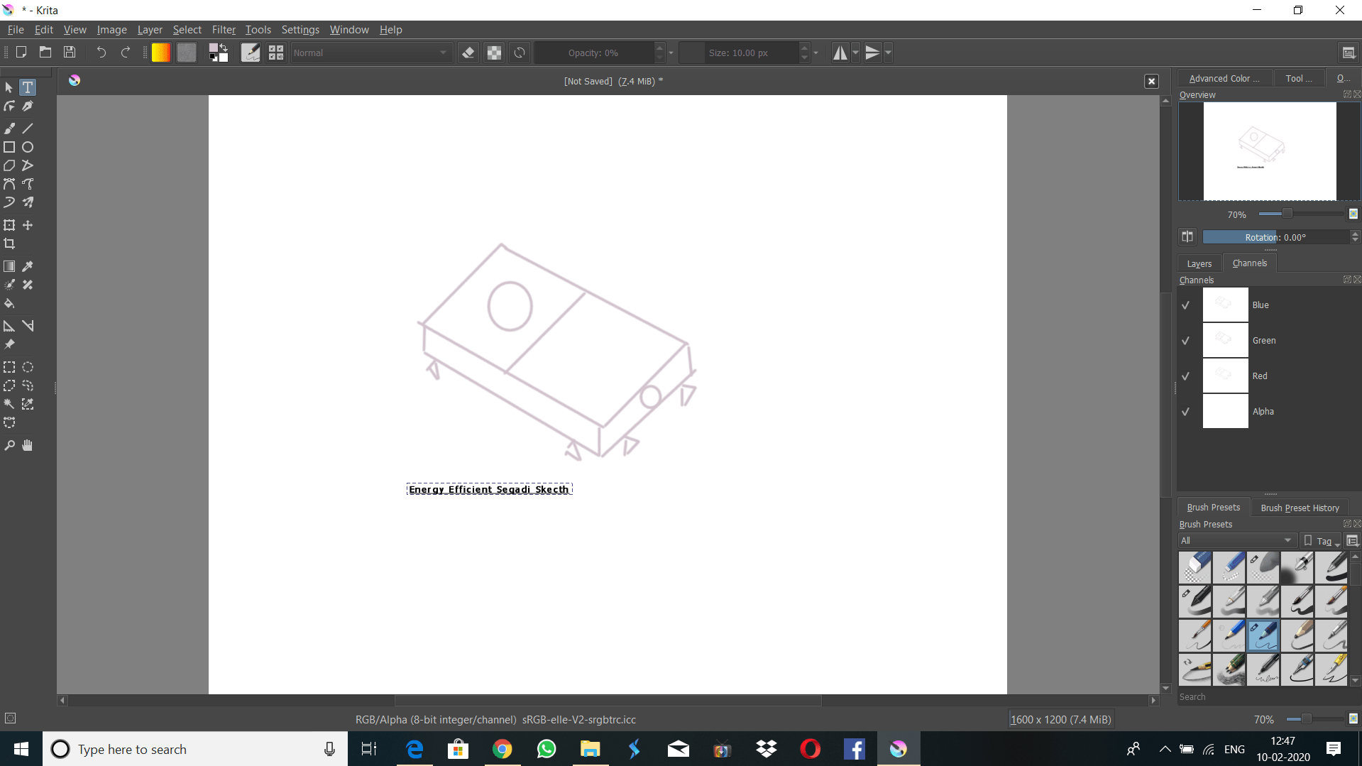
1. KRITA Software
KRITA is a open source painting software. It is used for concept art, texture and matte painters,
illustrations and comics purpose. It is also used for digital painting and animation purpose.
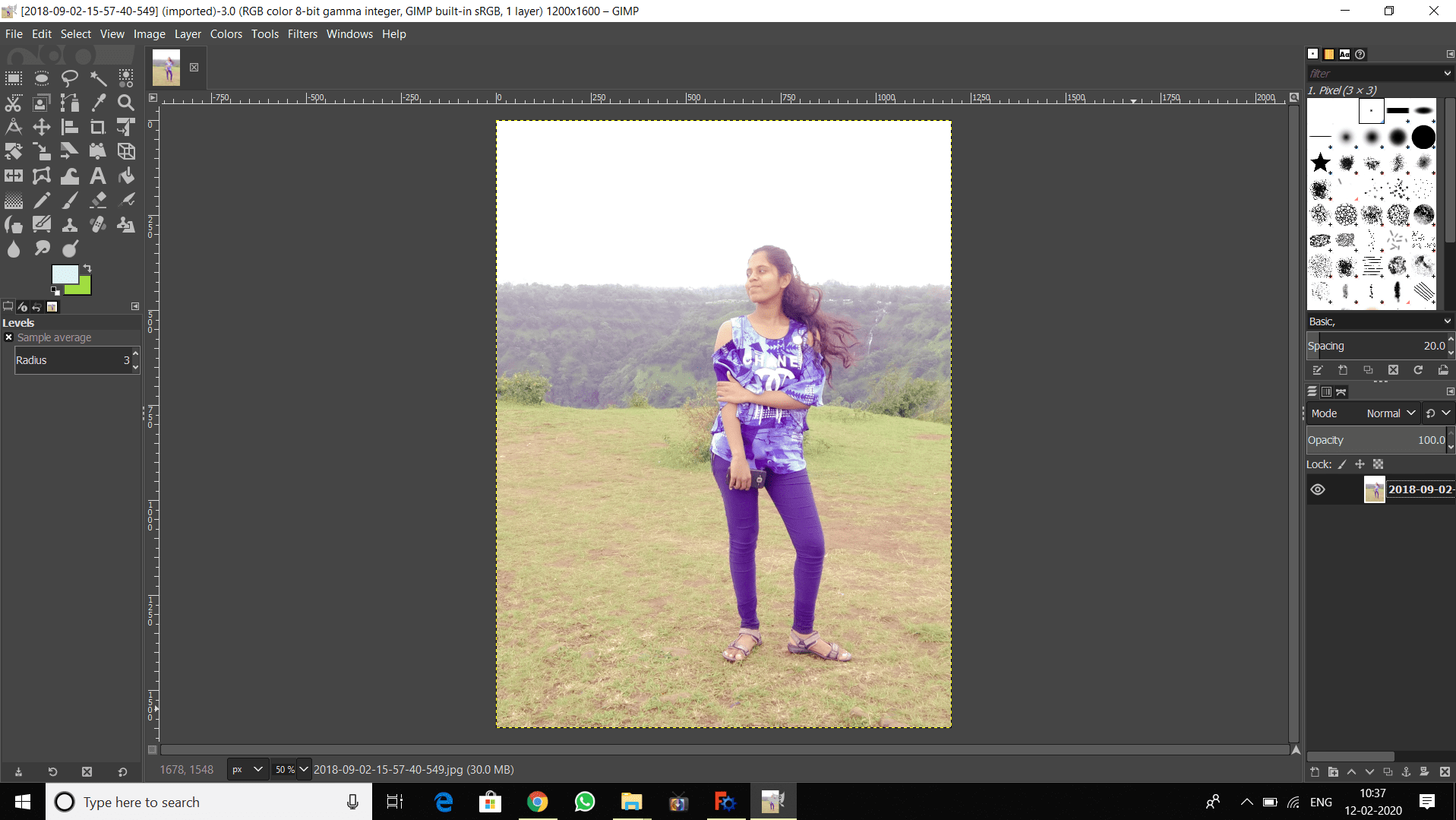
2. GIMP Software
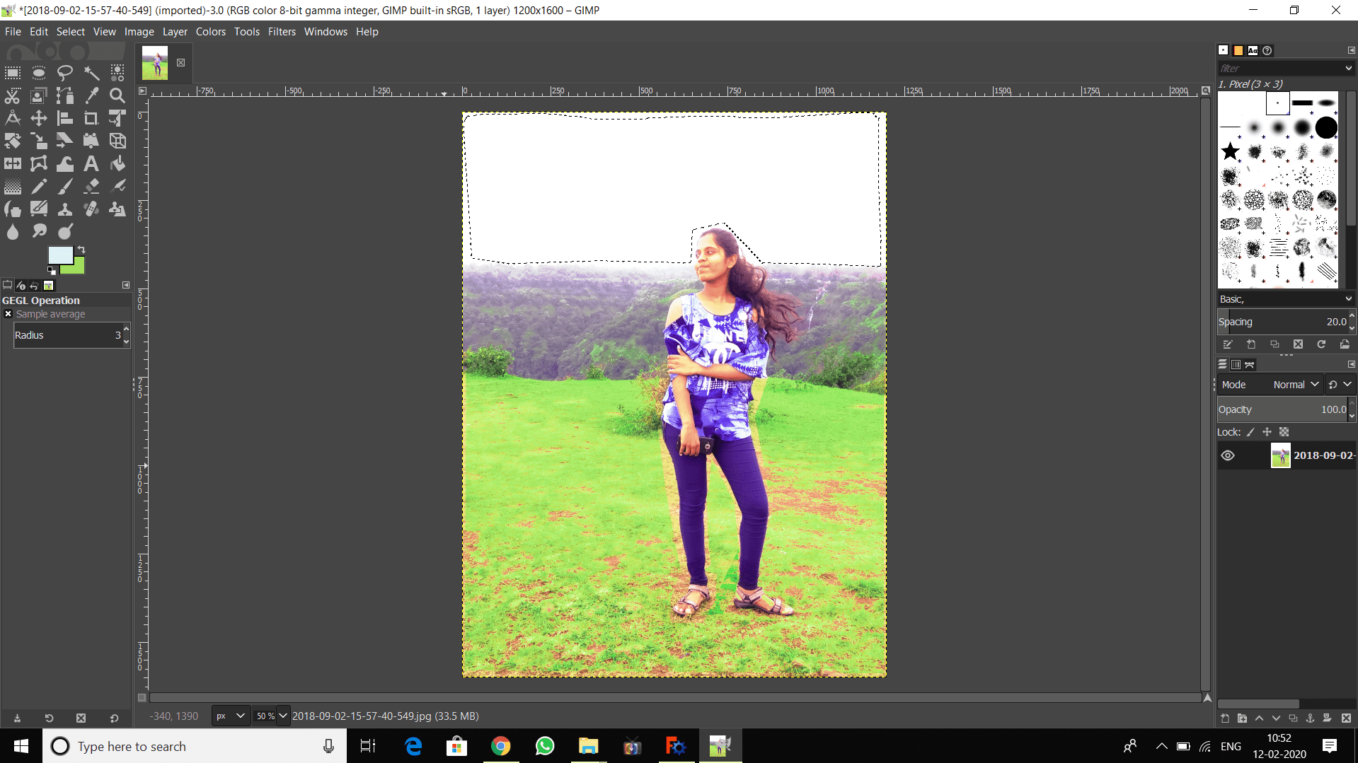
It is a GNU Image Manipulation Program. It is used for photo retouching, image composition and image authoring. I have installed GIMP 2.10.14 software. Here i have editing the picture of my sister by using ajust color curve, brightness and contrast, hue saturation command.
Before
After
Vector 2D Design
It is defined in terms of 2D points, which are connected by lines and curves to form polygons and other shapes. Each point has a defined position on x axis and y axis of the work plane.Coreldraw, Inkscape,FreeCAD such software is used for vector 2D design. In this assignment. I have tried all this for to draw given diagram.
1.Inkscape Software
It is a professional vector graphics editor. Inkscape is free and open source software.
It is generally used for illustrations, icons, logos, diagrams,maps and web graphics.
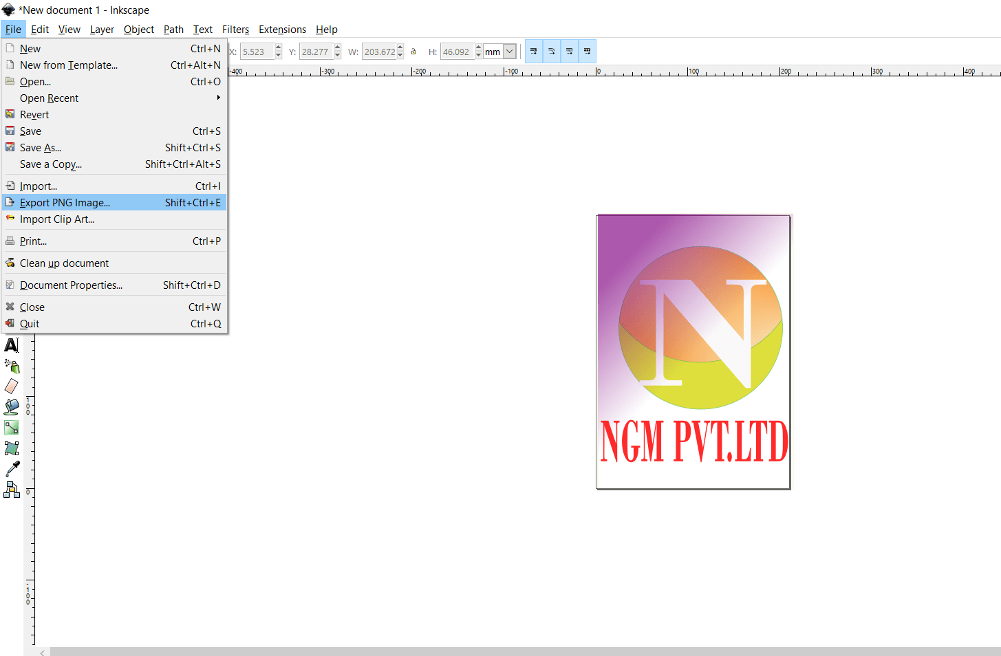
Here i created flex with LOGO.
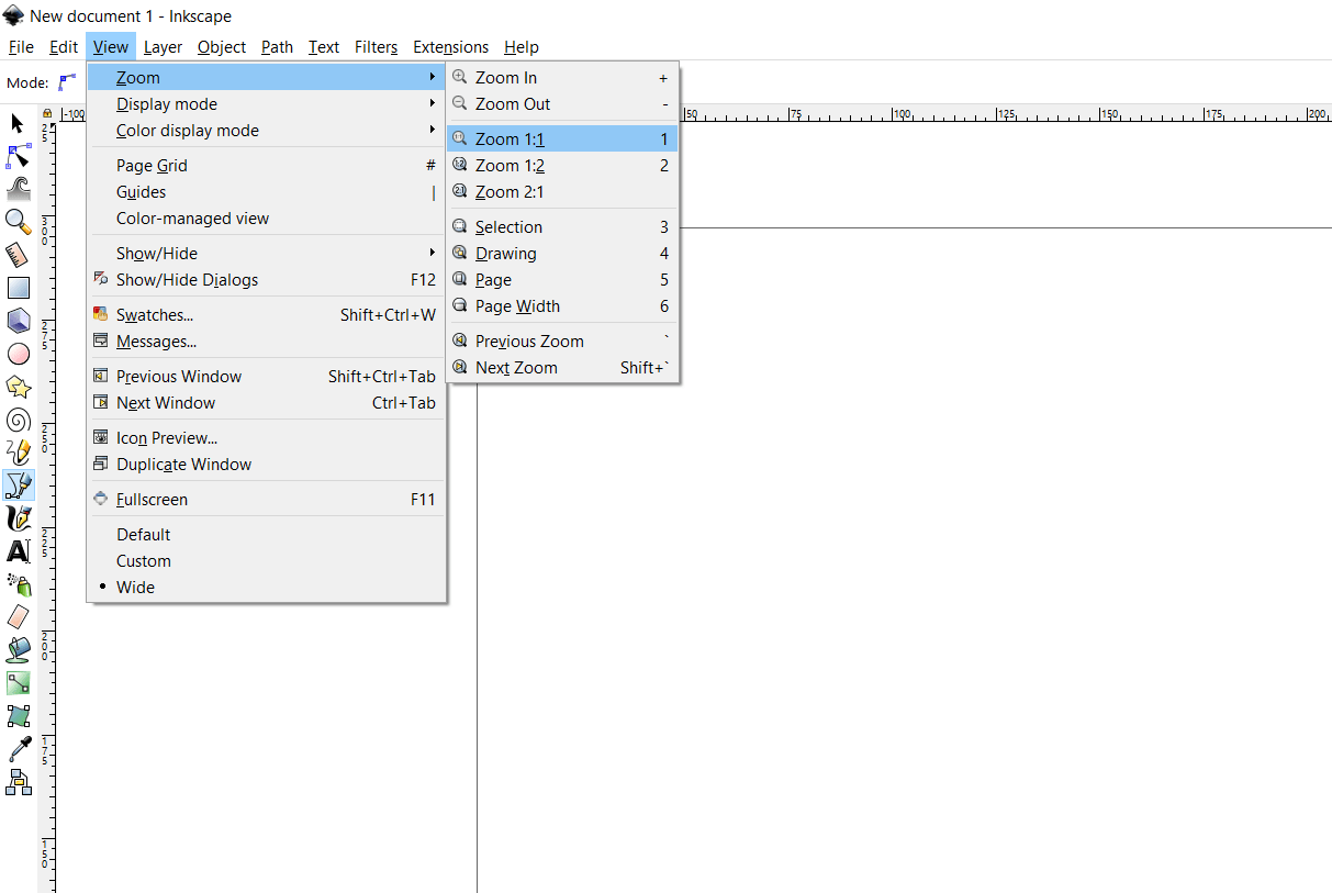
Select New document>select View>Zoom>different zoom option are given, according to our requirement, we will select it
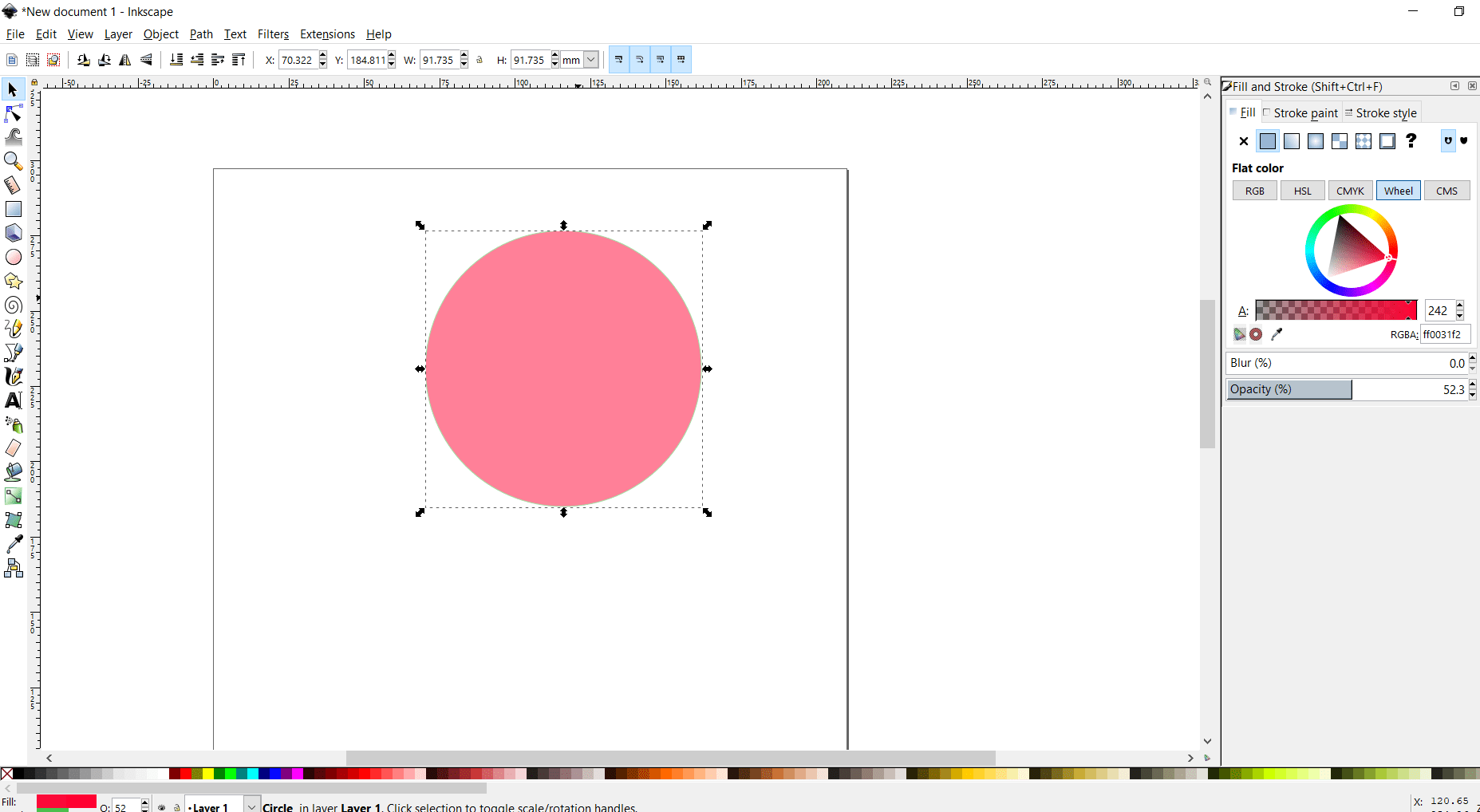
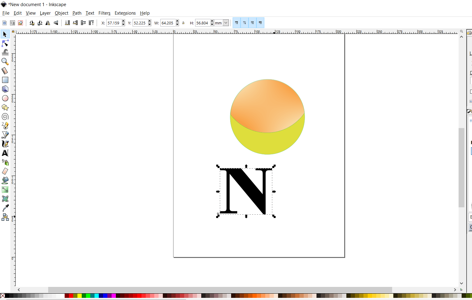
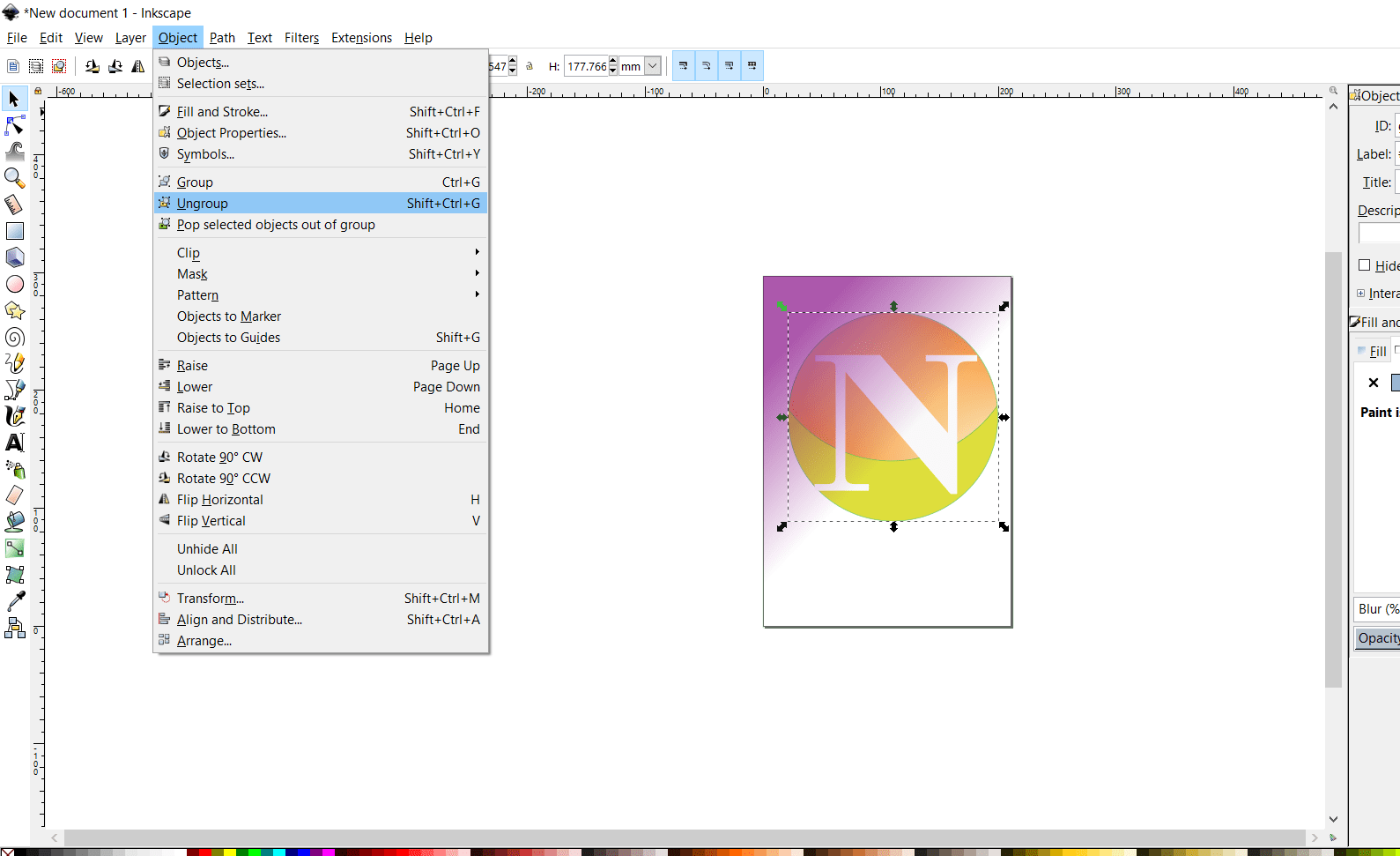
creted circle, by selecting draw circle option from left side, fill the color, by selecting color from bottom
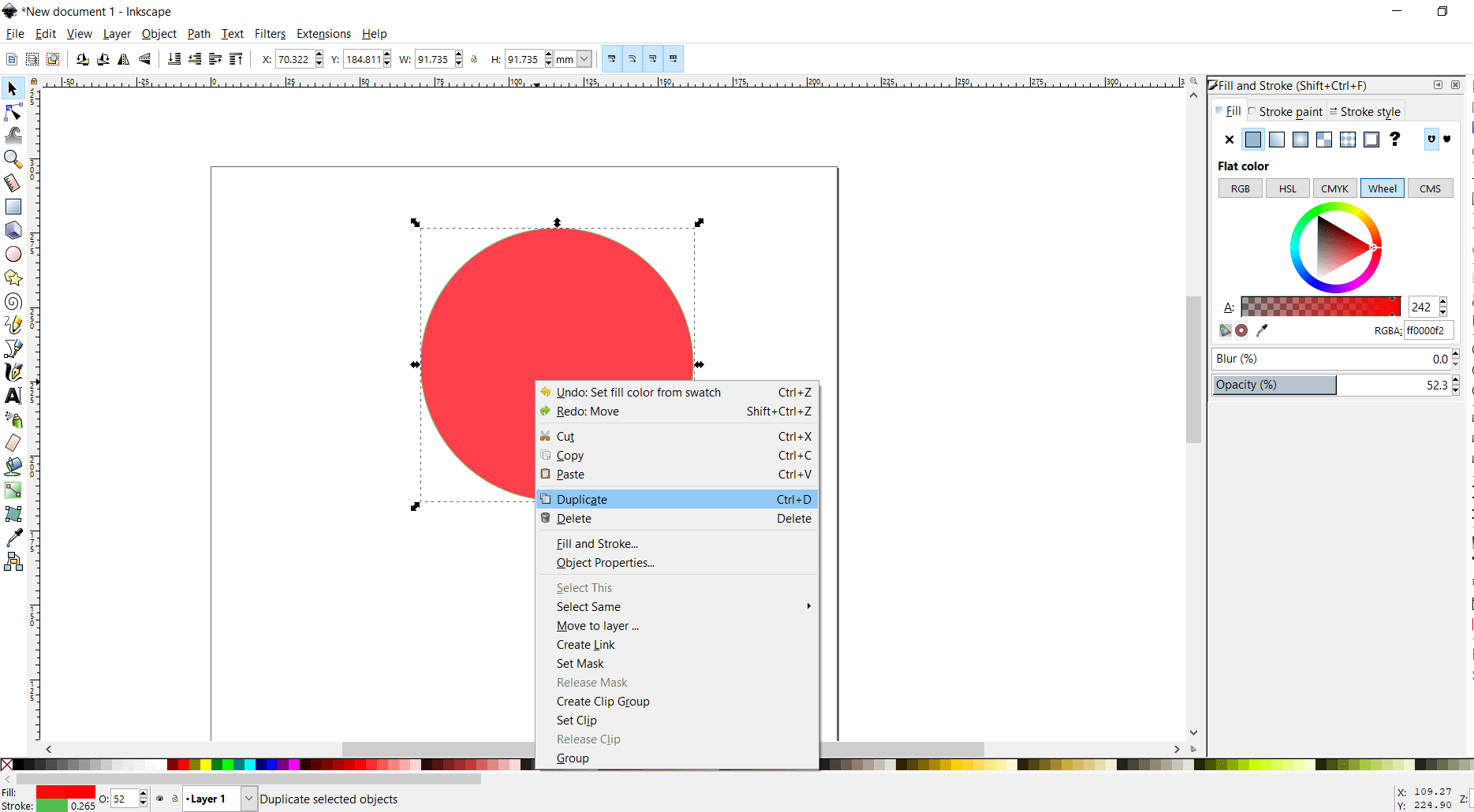
creted duplicate of the same object, by right clicking
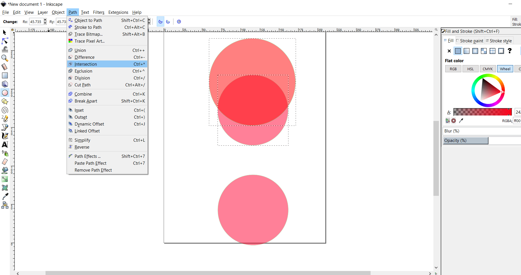
The dimeter of the duplicate circle is increased little bit>drag move to the top>intersect both the object
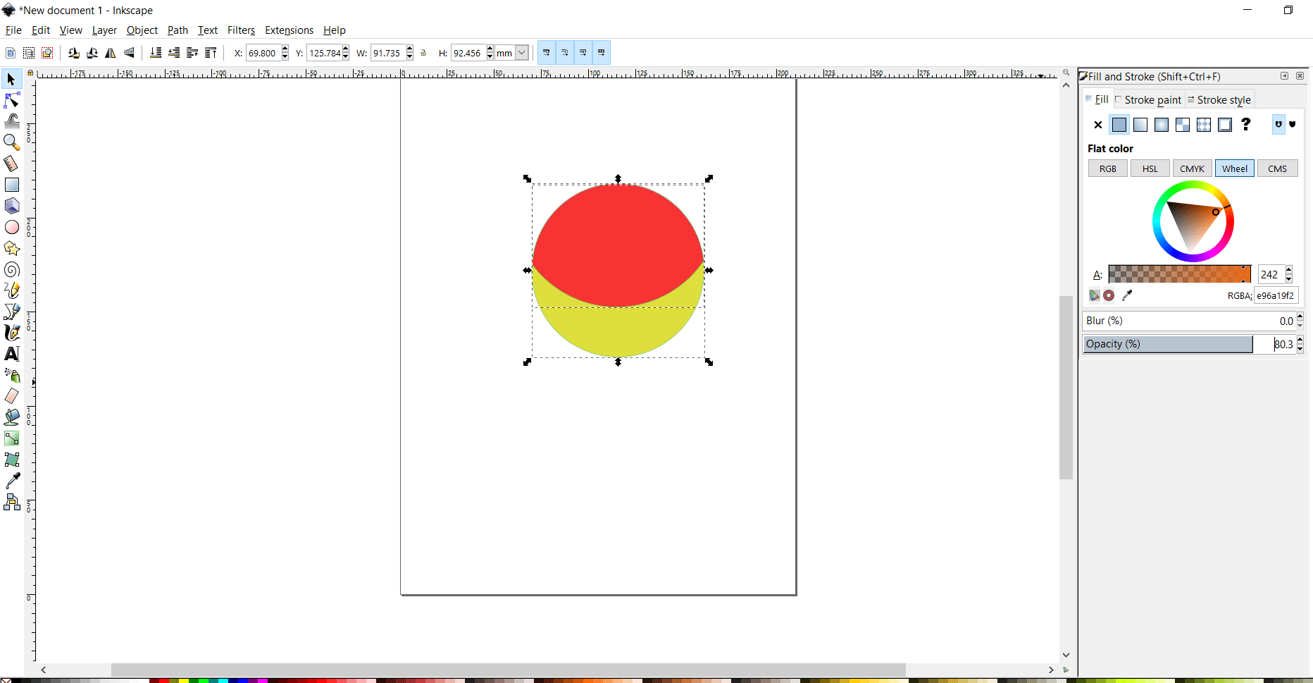
The color will changed and opacity is increased, option is given on right side
Write name by select text option>draged to logo>color is also change of the name
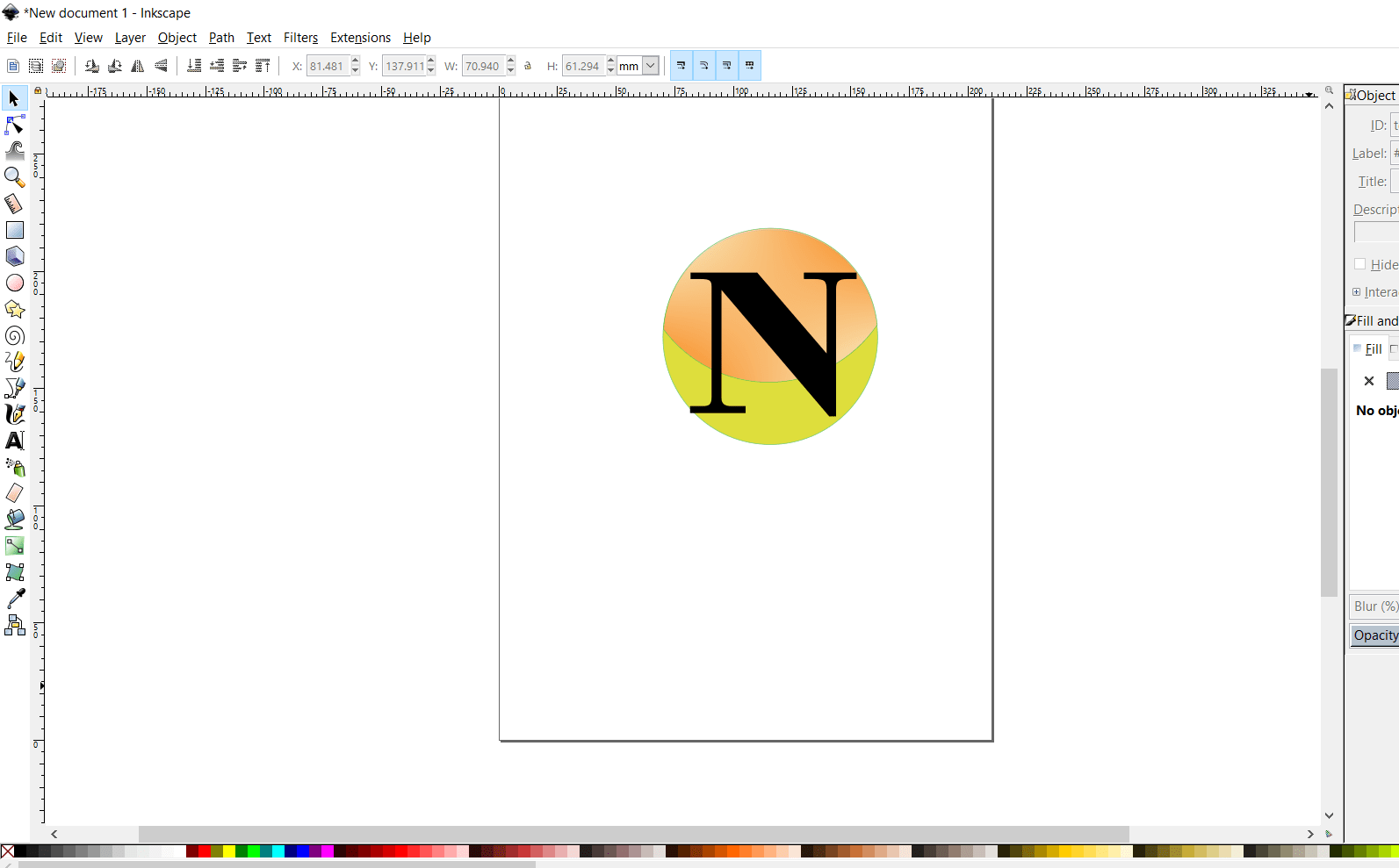
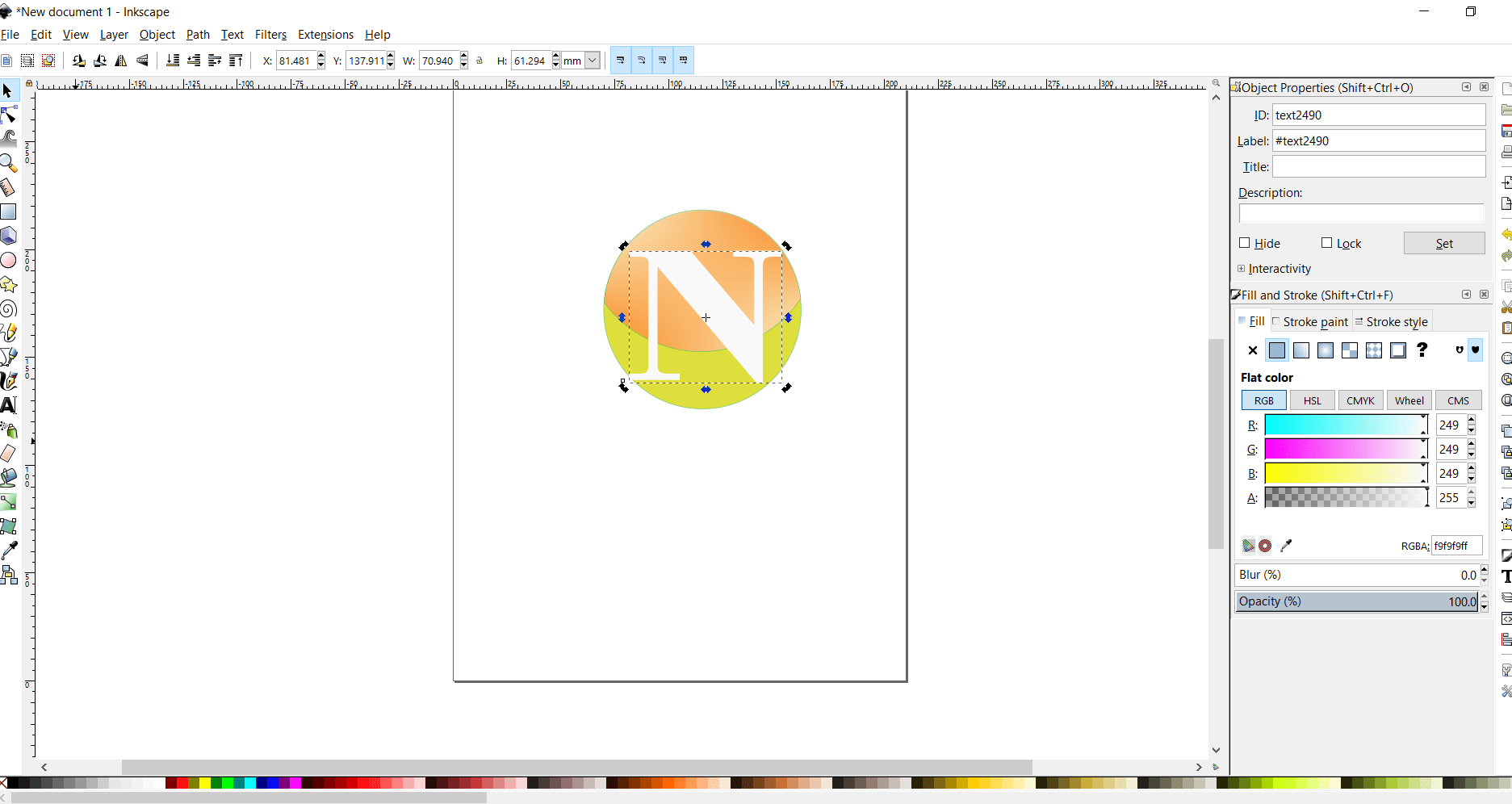
Created the box of page size> color of the page is changed>fill is also changed>option is given on right side
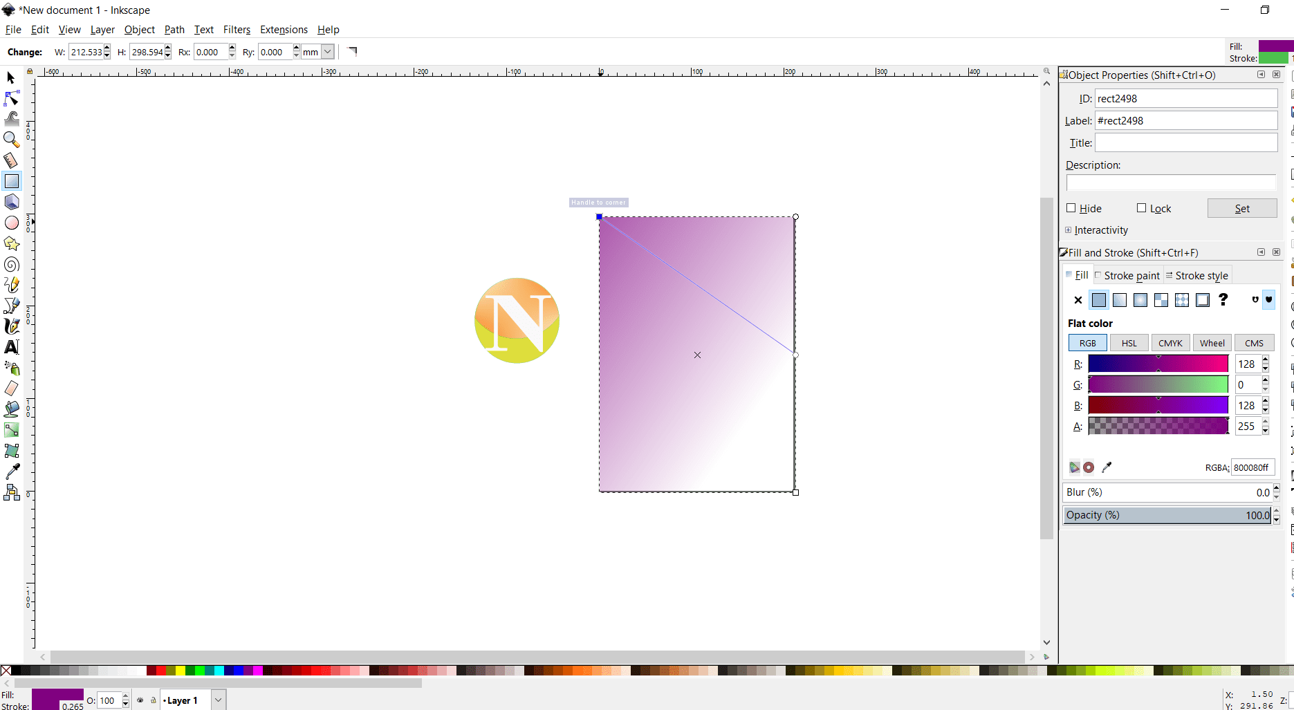
Ungrouped the images>that means the single image is create of this different object>export the png.
2.FreeCAD Software
FreeCAD is open source software which is used for 2D and 3D drawing. For vector 2D design, I have also tried a FreeCAD.
I tried a parametric design in FreeCAD, which is a part my Assignment 3
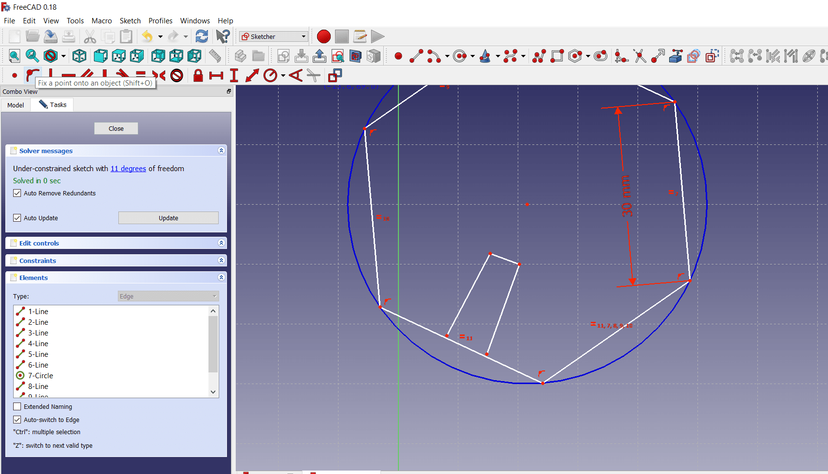
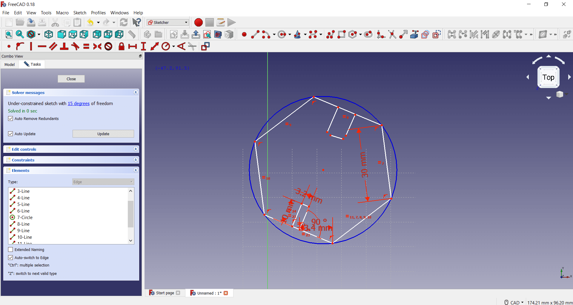
Open the software>select sketcher workbench in dropdown menu>draw any drawing here I have
drawn hexagon
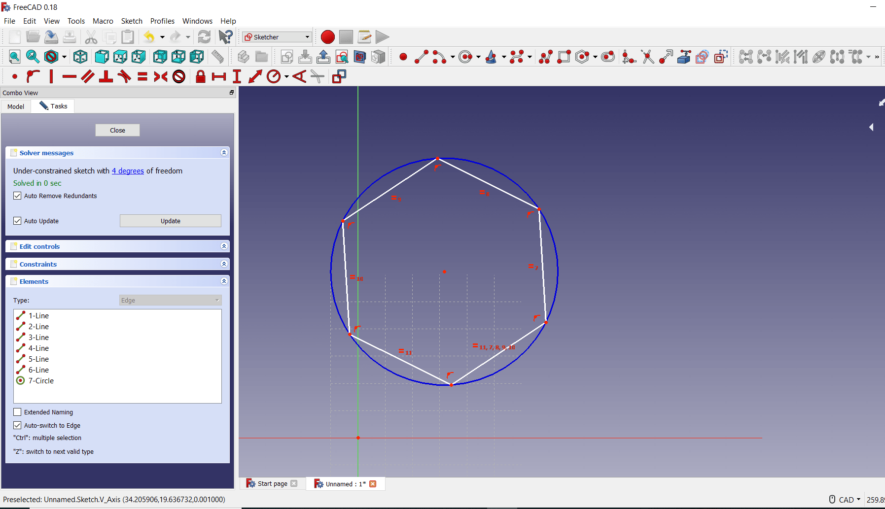
Noe give the dimesnion to the side by using the dimension menu on top bar
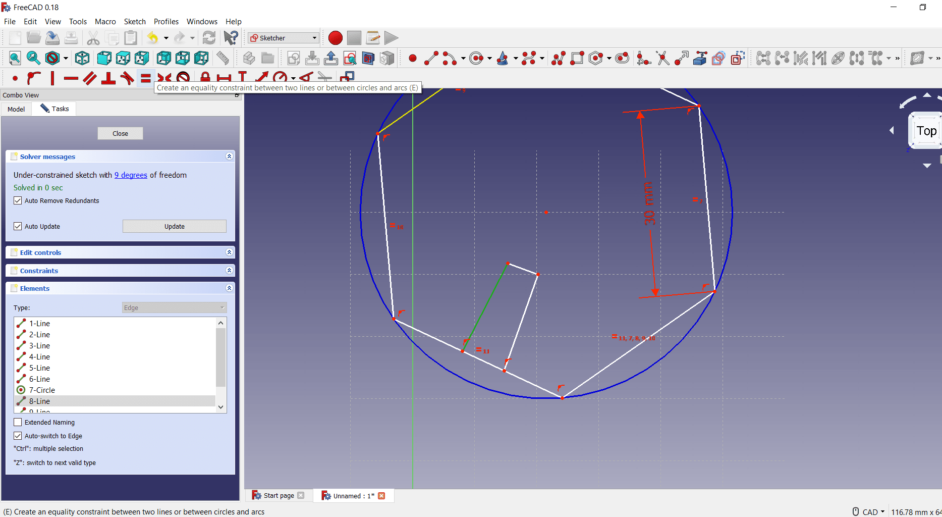
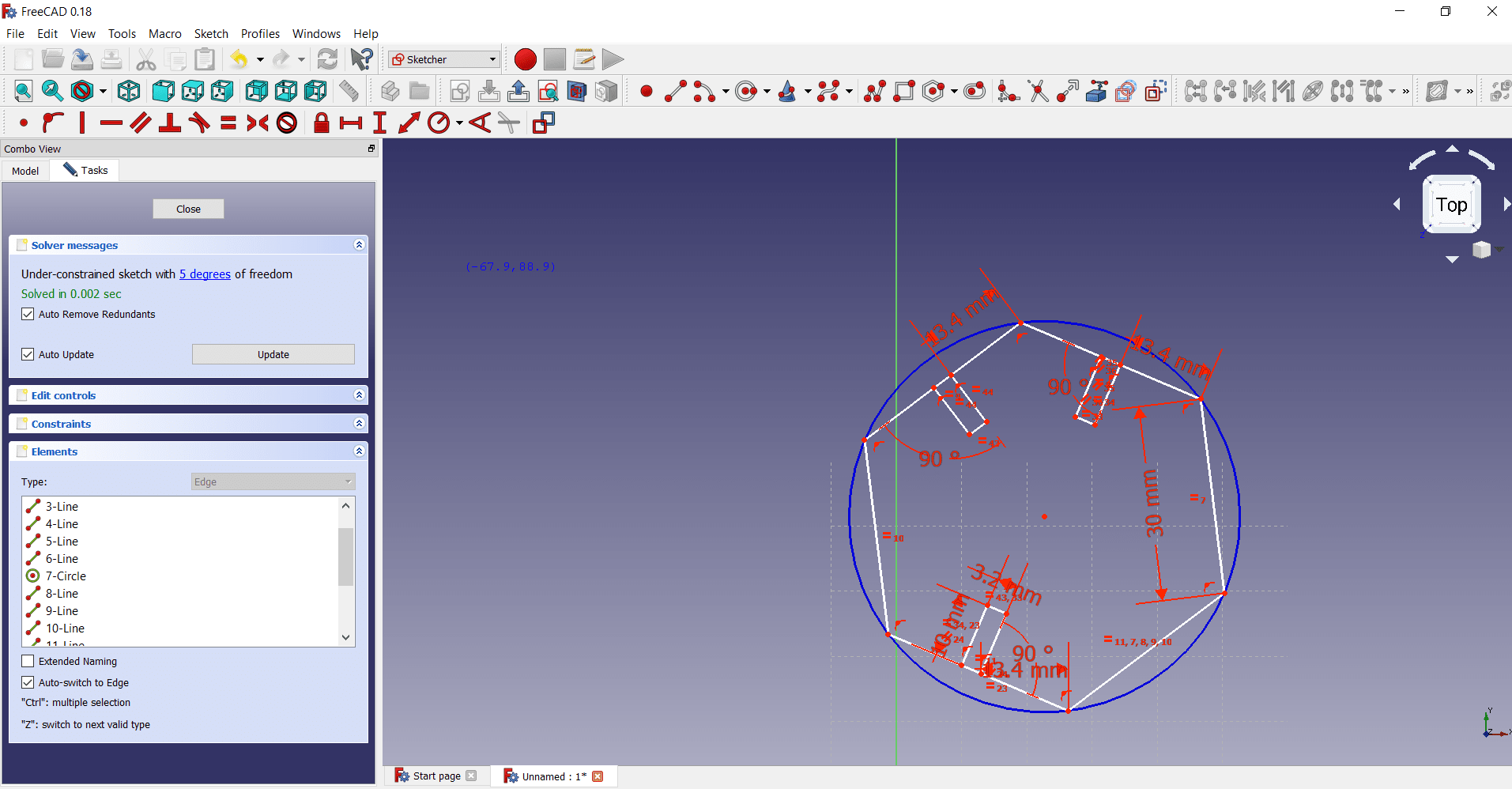
Draw the three different line>apply the constraints(option given in top bar) here i have applied equality, parallel, angle, equal distant constraints
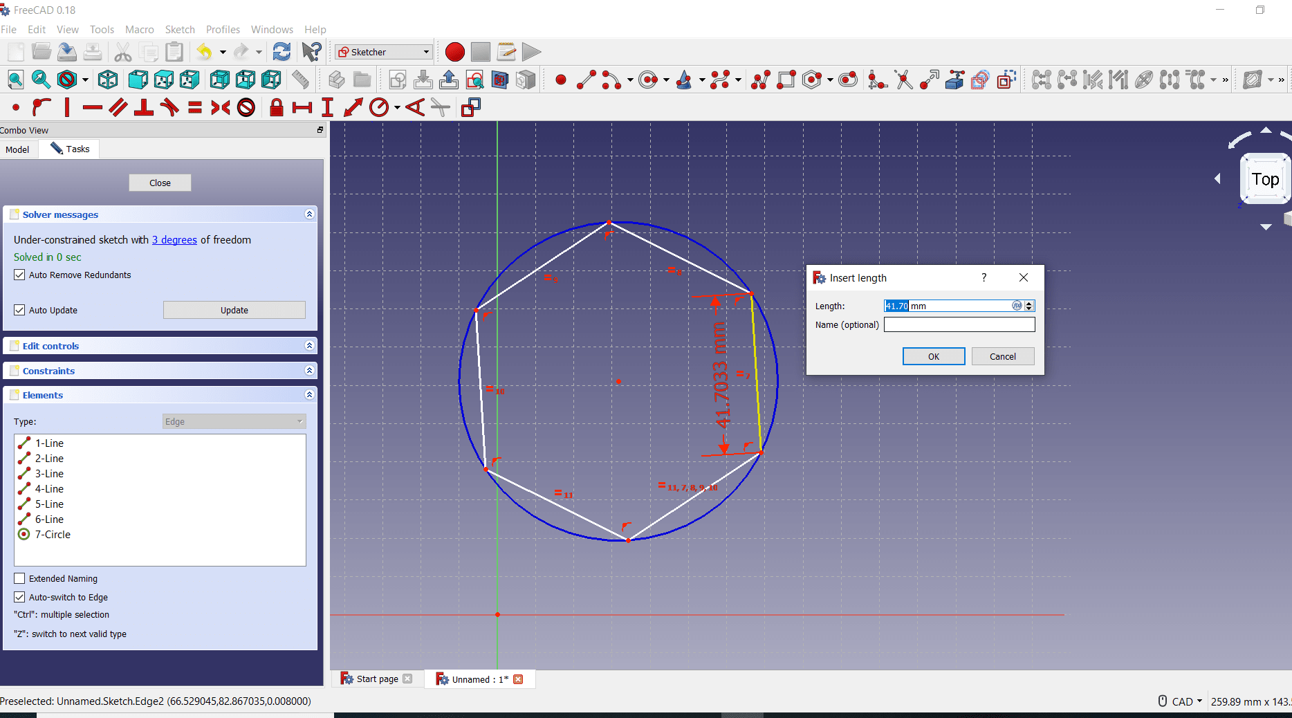
Put the required dimension to the side
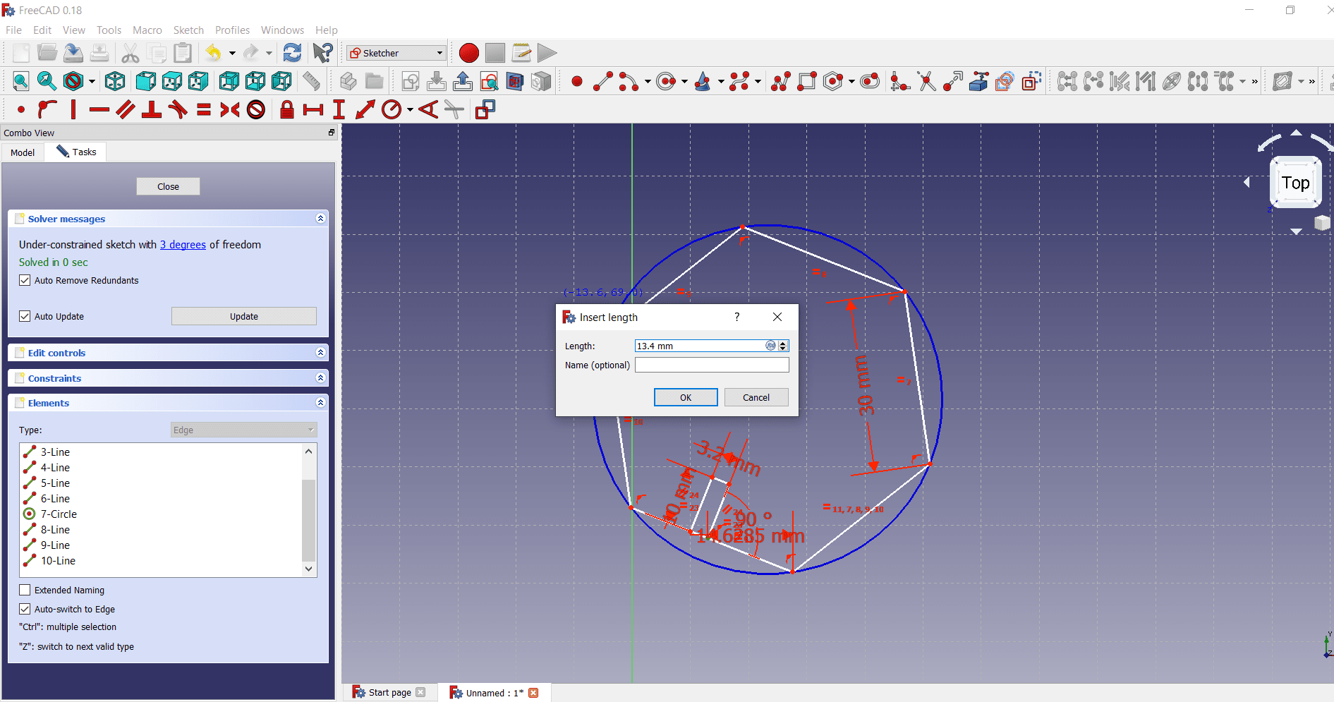
Give the required angle to the line , by using the angle menu from top. The first slot is ready now
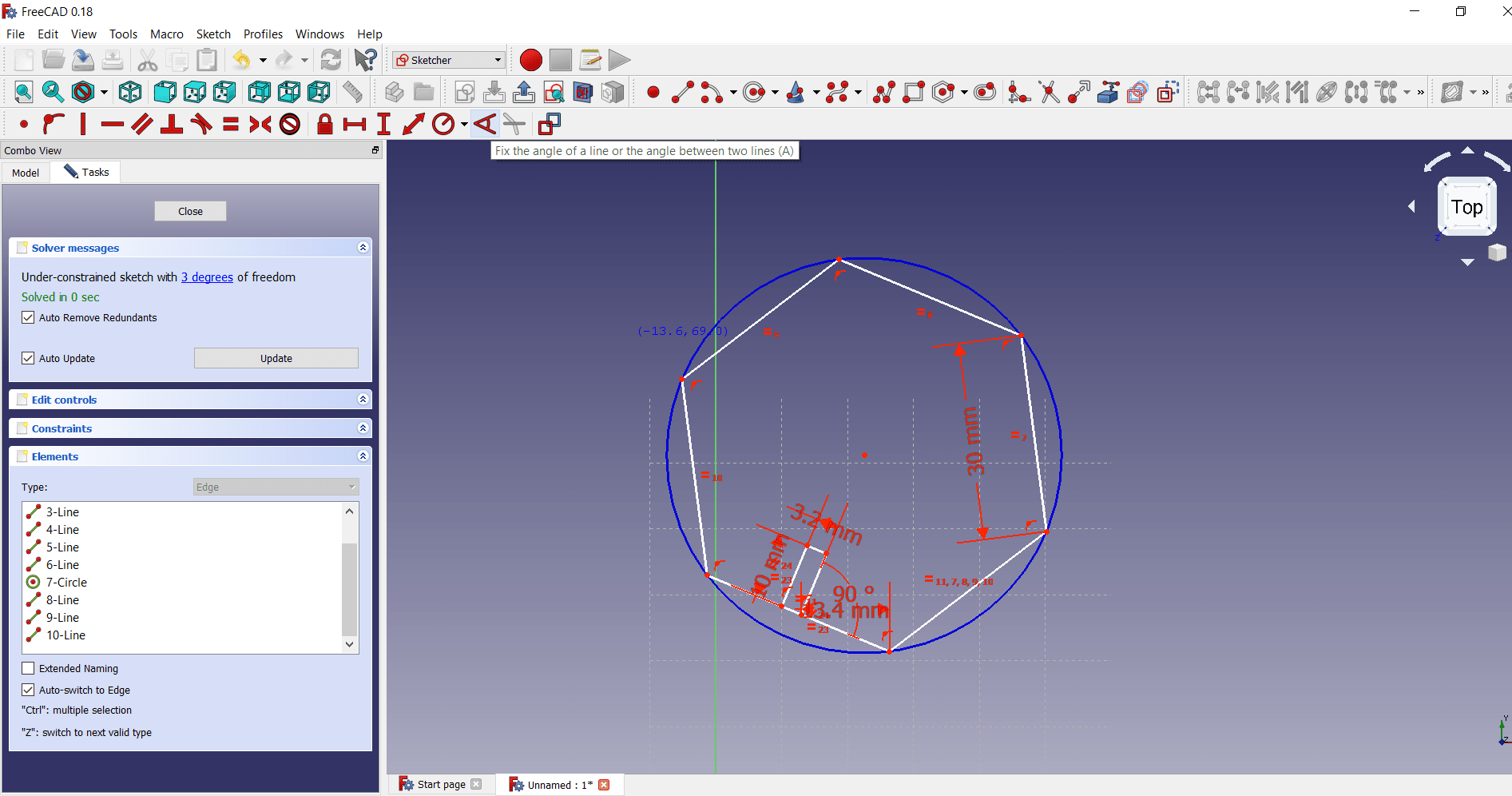
With reference to first slot applied on side, same slot we can draw on another side and applying the same constraints as like first slot
Similarly drawing the slot on next remaining side
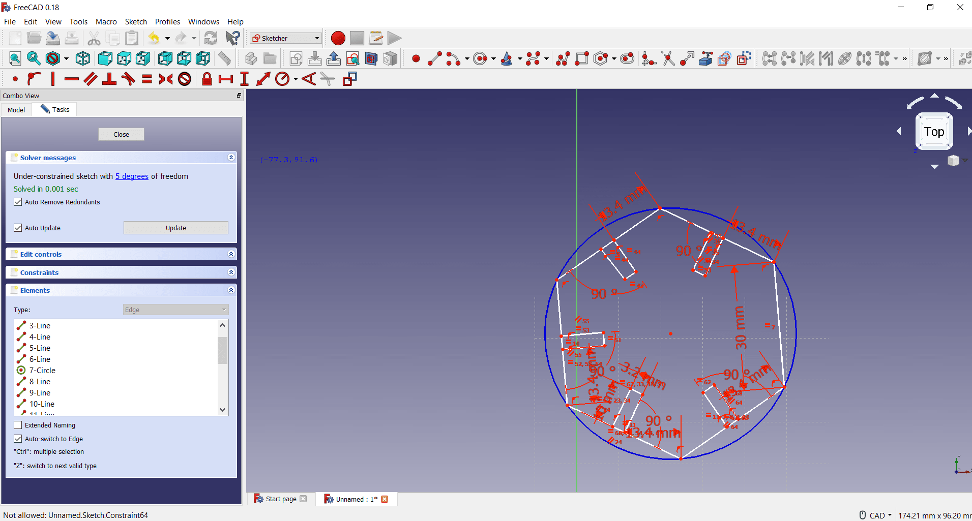
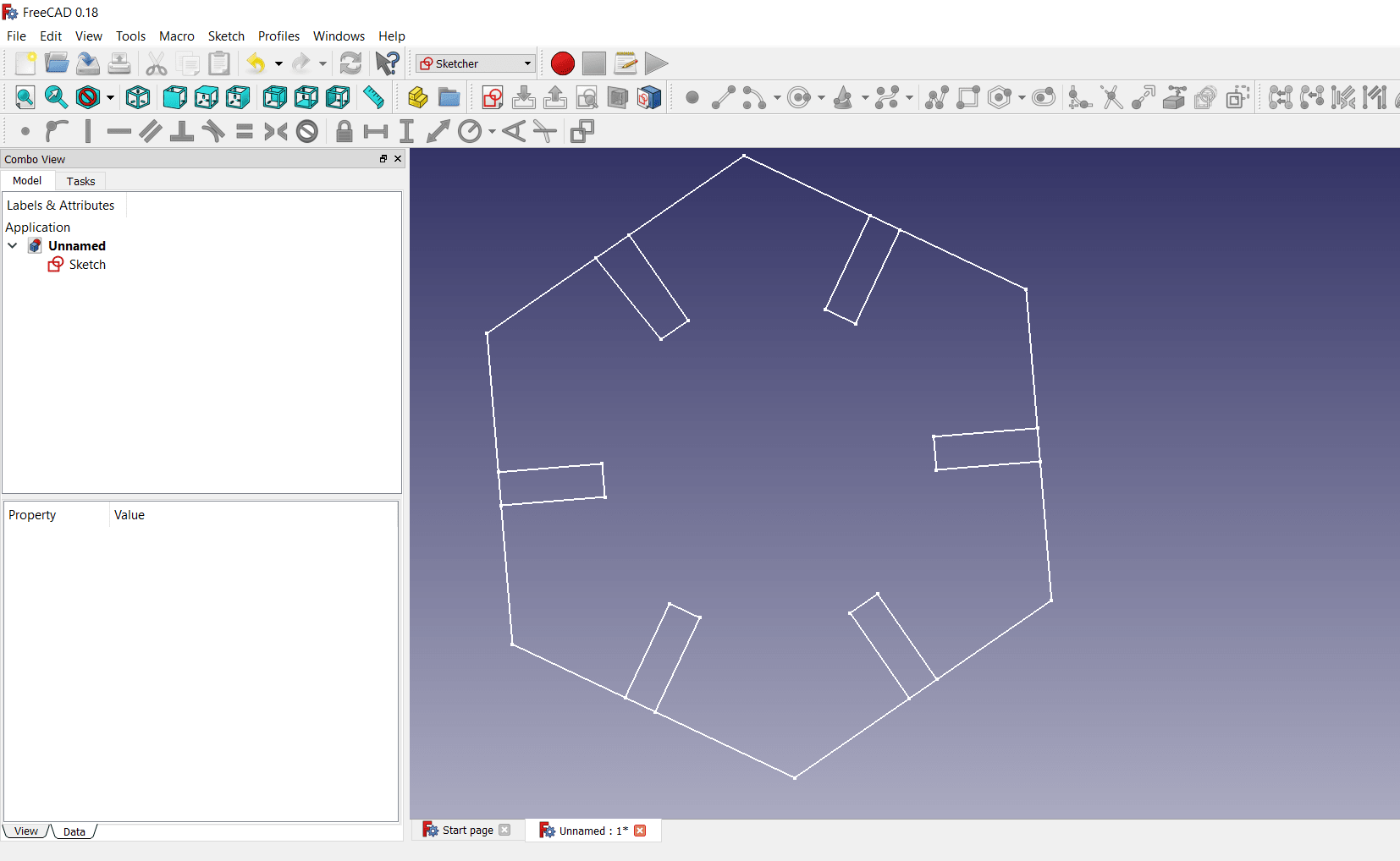
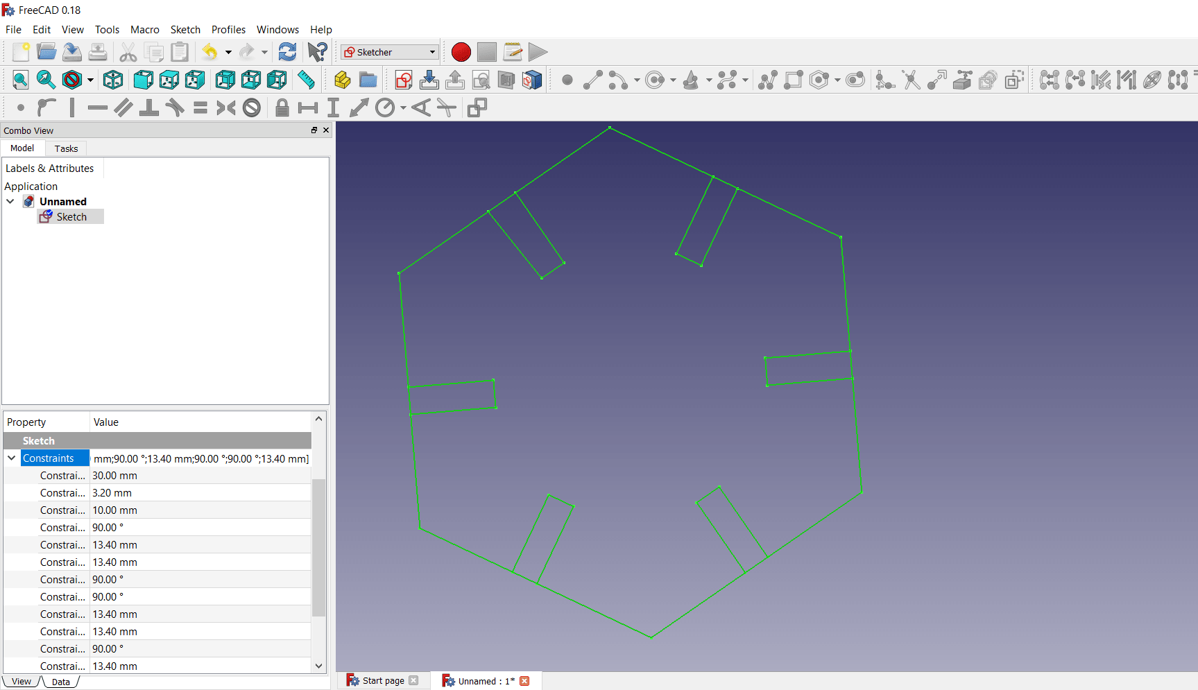
The final 2D sketch with dimension is ready now
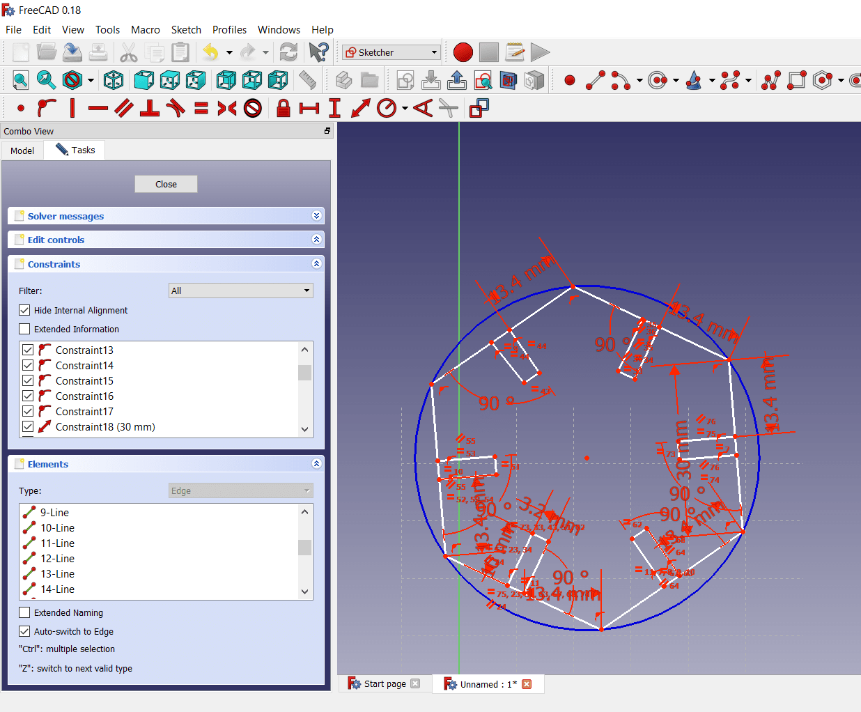
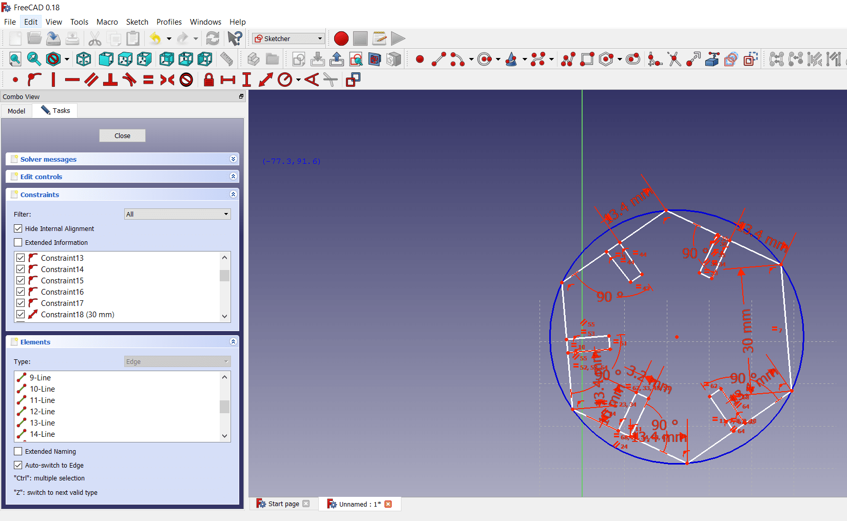
Press the esc button>the final sketch will be like this, here if i want change any one dimension, that will automatically applied to all i.e. known as parametric design. The number of constraints is shown on left side
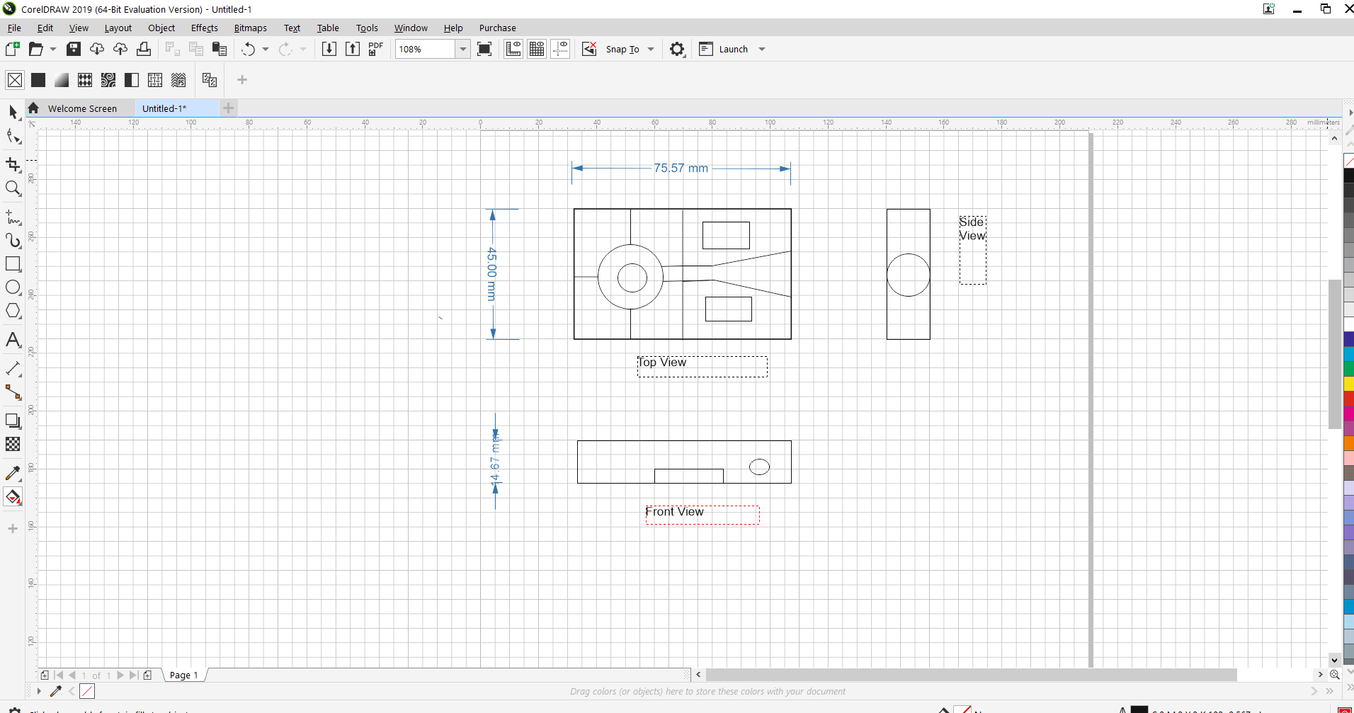
3.Coreldraw Software
It is a vector graphics editor developed and marked by Corel Corportion. It is used for
• New non-destructive effect for bitmap and vector object
• To control object, layers and pages
• To improve pixel workflow for pixel perfect documents
I have develop the front view, top view and side view of my project sketch using Coreldraw.
3D Design
The product has three dimension i.e. height, width and depth. 3D modelling is th process
of creating a 3D representation of any surface or object by using polygons, edges and vertices in simulated 3D spaces.
In 3D modelling movies animations and video gamesalso created.
Different tools are used for 3D design. In this assignment
I have tried to develop my project 3D model using FreeCAD and Solidwork.
1. FreeCAD Software
FreeCAD is a multiplatform (i.e. Windows, Mac OS and Linux platform) and it is open source software.
It is general purpose 3D CAD modelling applications made for to design real life object
FreeCAD also used for Parametric modelling which is a type of modelling where the shapes of the 3D object are controlled by parameters. This parameter has been modified
at any times even after the object has been created.
Open FreeCAD>create new file> by clicking on dropdown menu>select workbench sketcher menu for 2D design
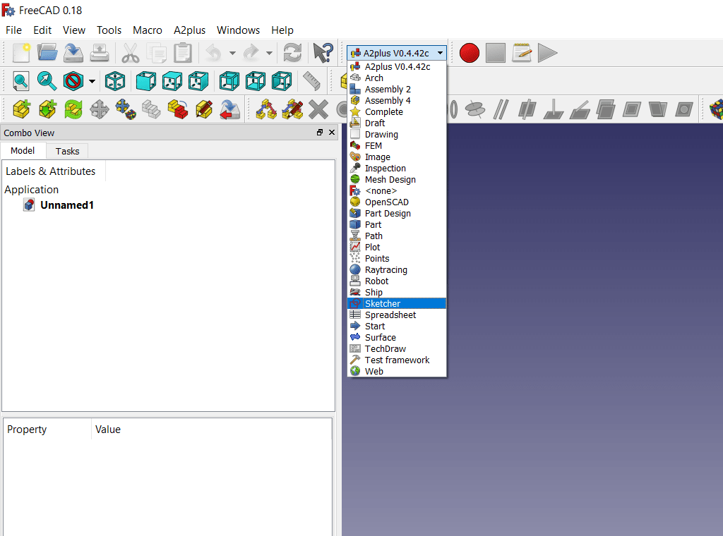
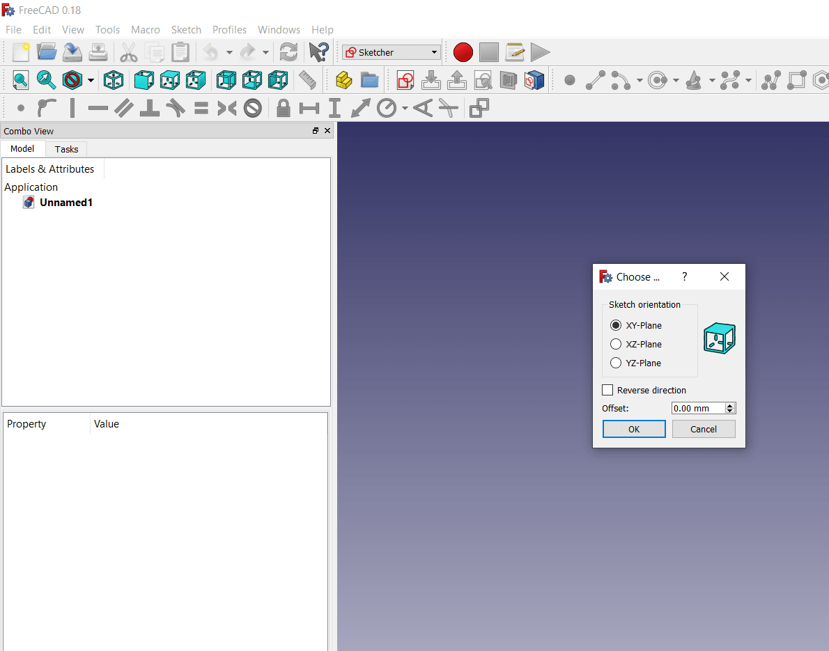
Below sketcher, there is create new sketch menu, click it and select XY plane
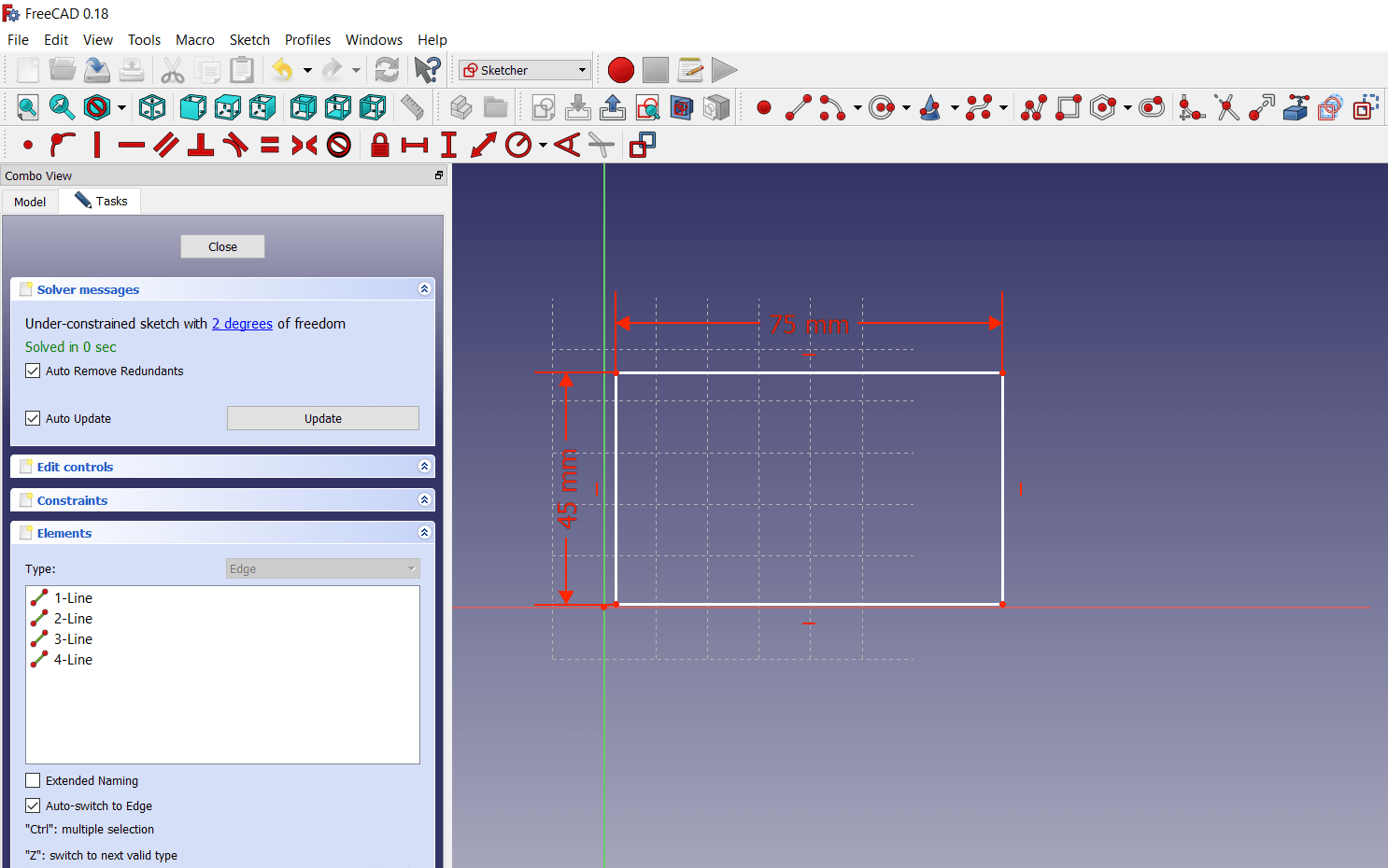
Draw the 2D sketch, give dimension, press esc.
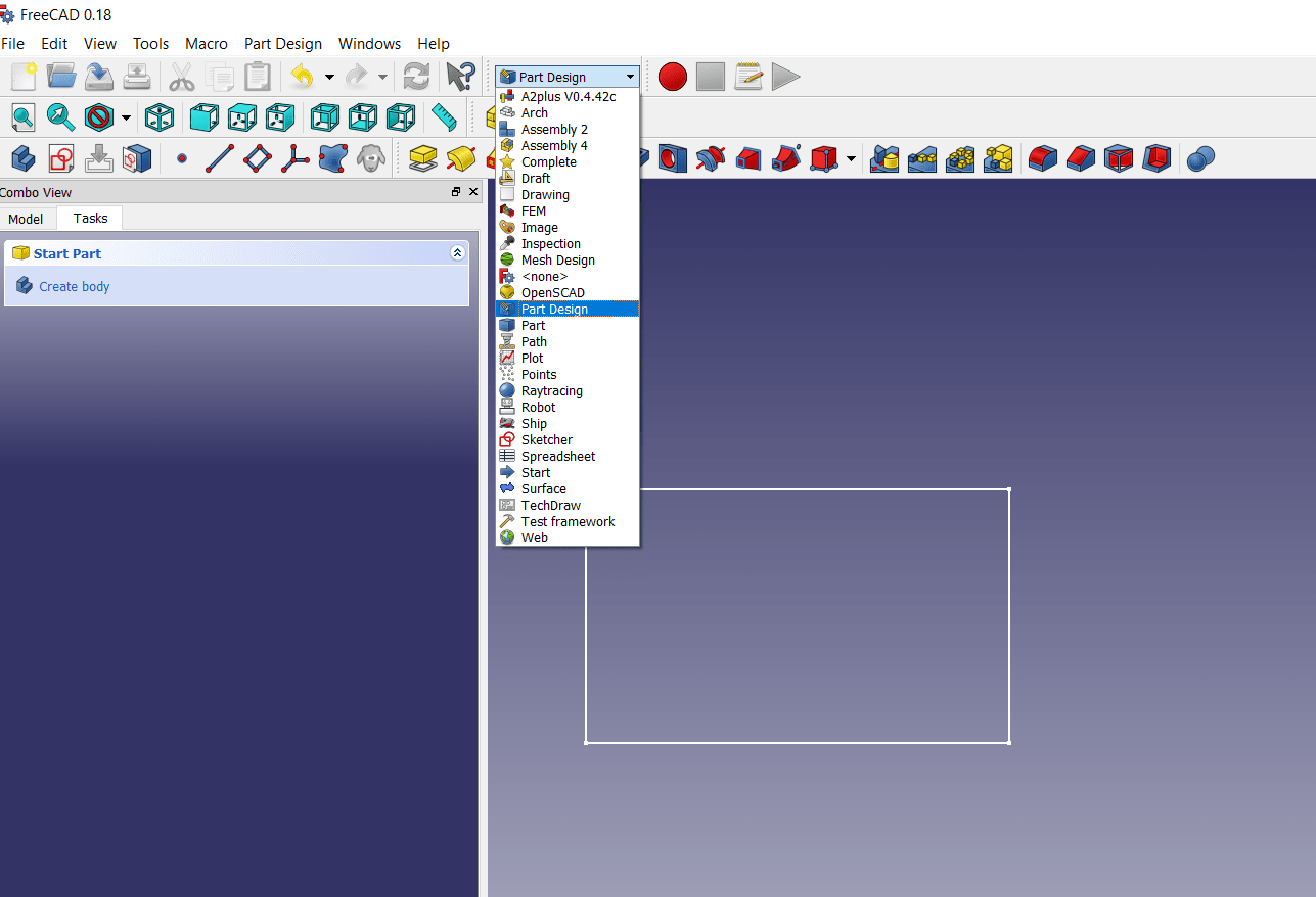
Select part design in dropdown menu
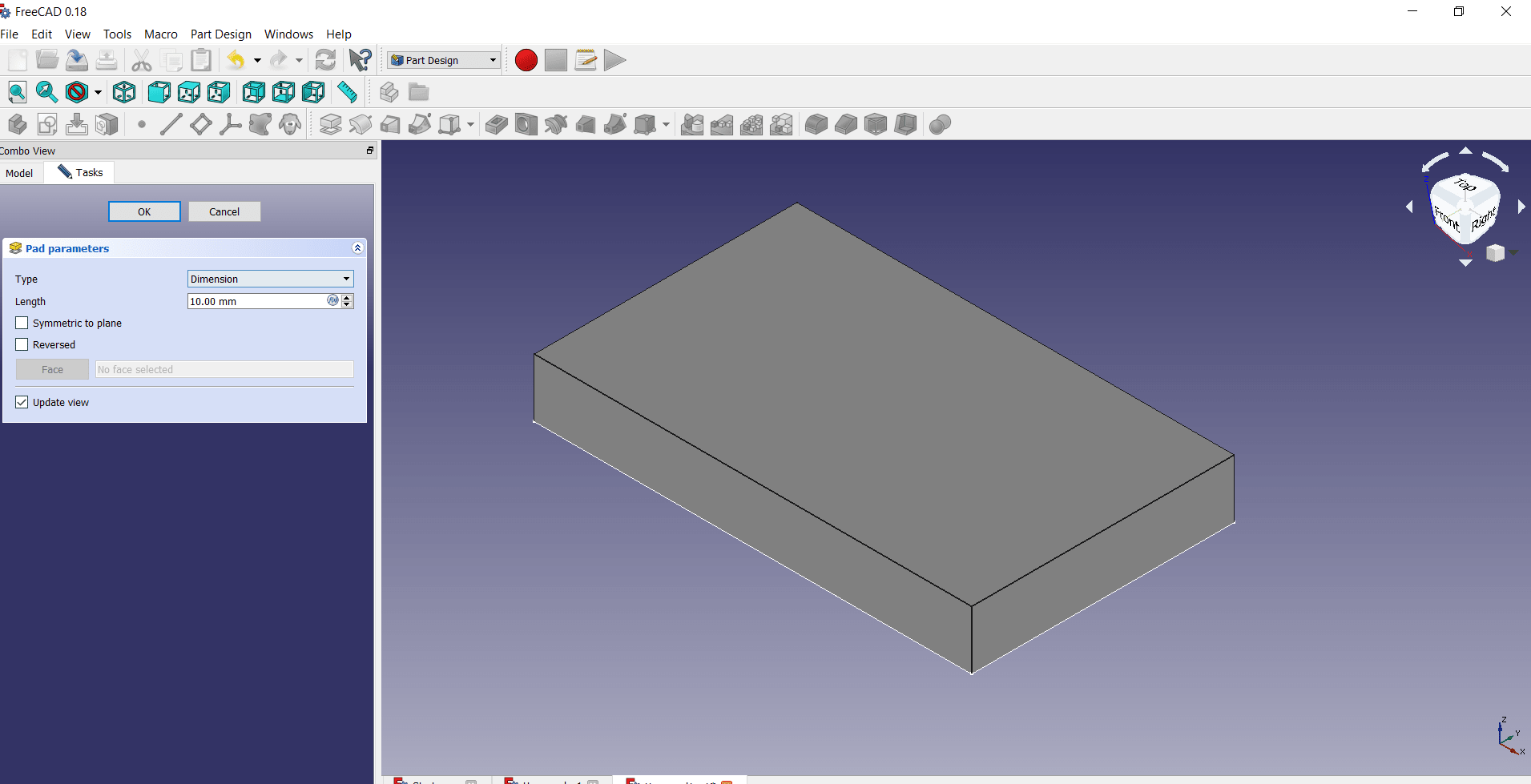
Create body>create pad>make independent copy>give the height as per requirement on left side
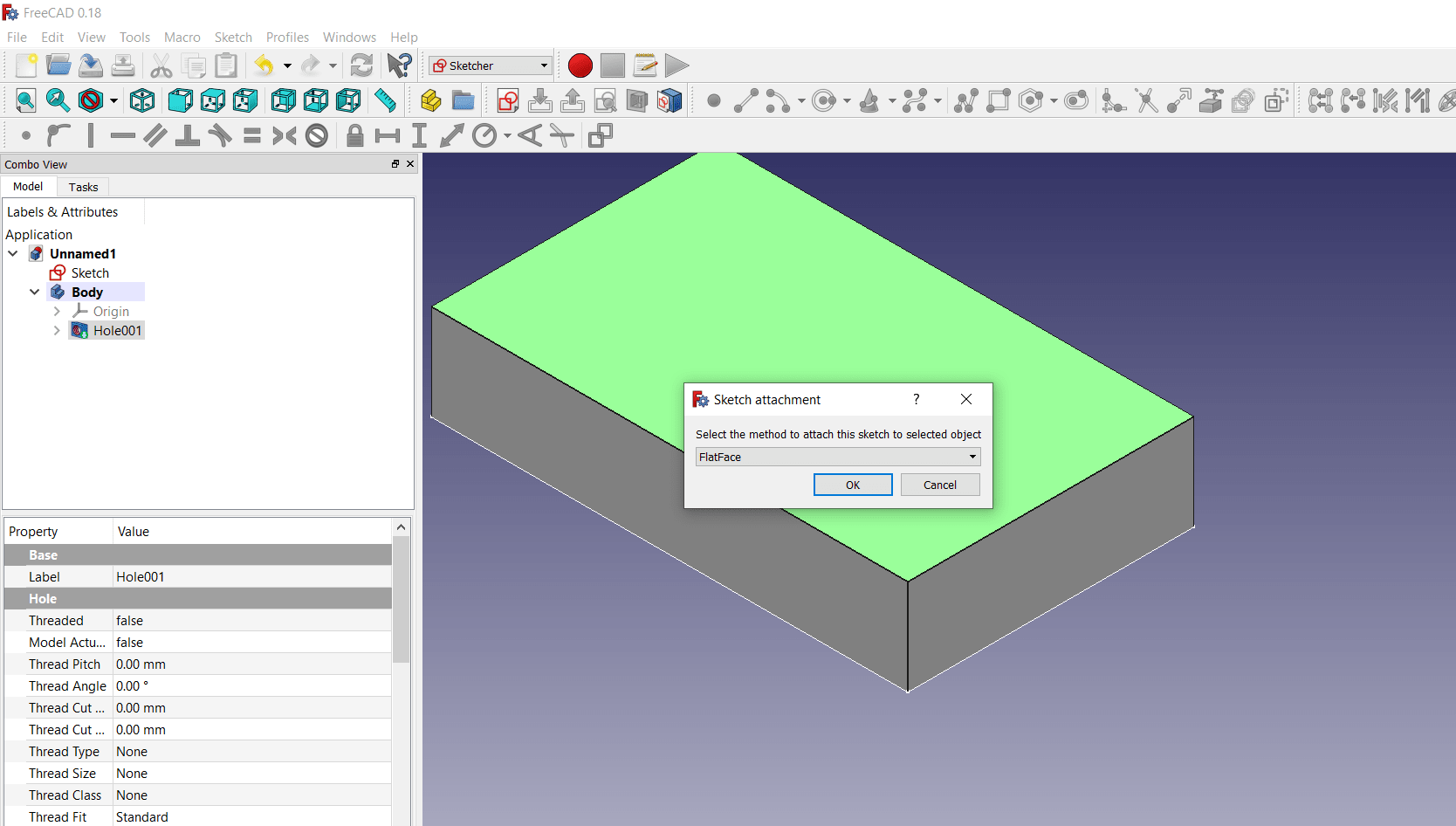
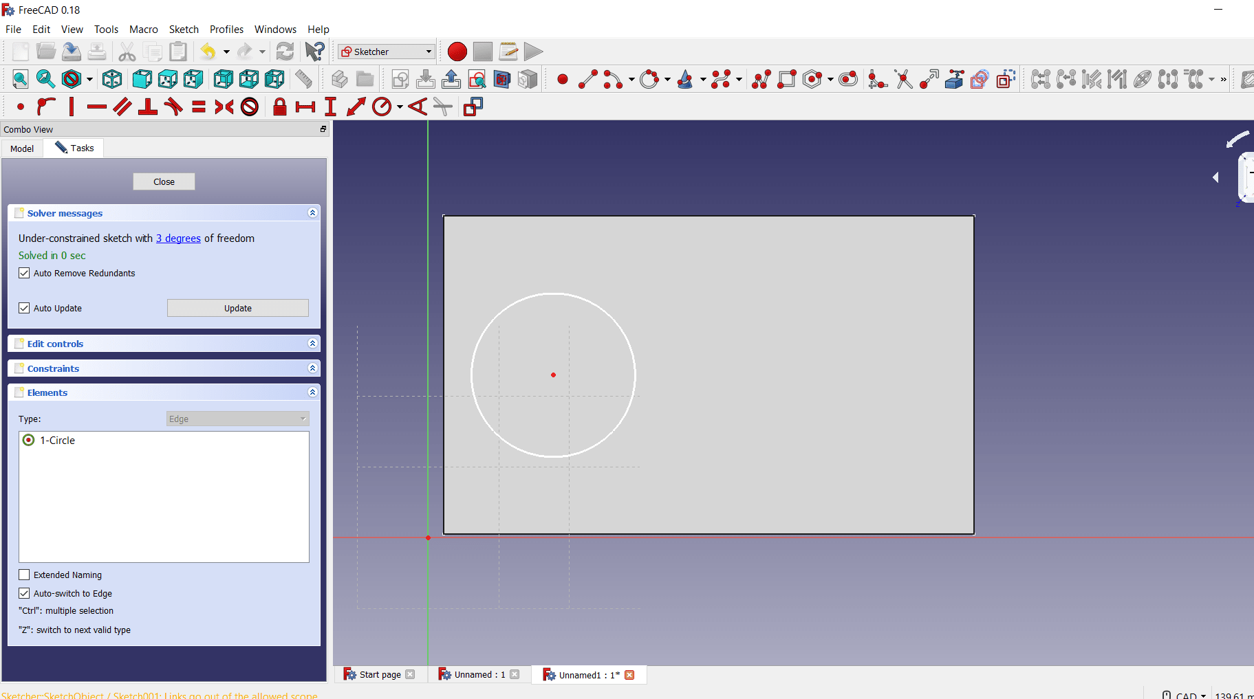
Then again back into the sketcher menu, select the flat surface on which we have create another design,suppose here i have to create hole and pocket on this side, the draw the sketch of hole and pocket with dimension
again go into part design>create body of the sketch> the hole and pocket will create> the final shape is like this
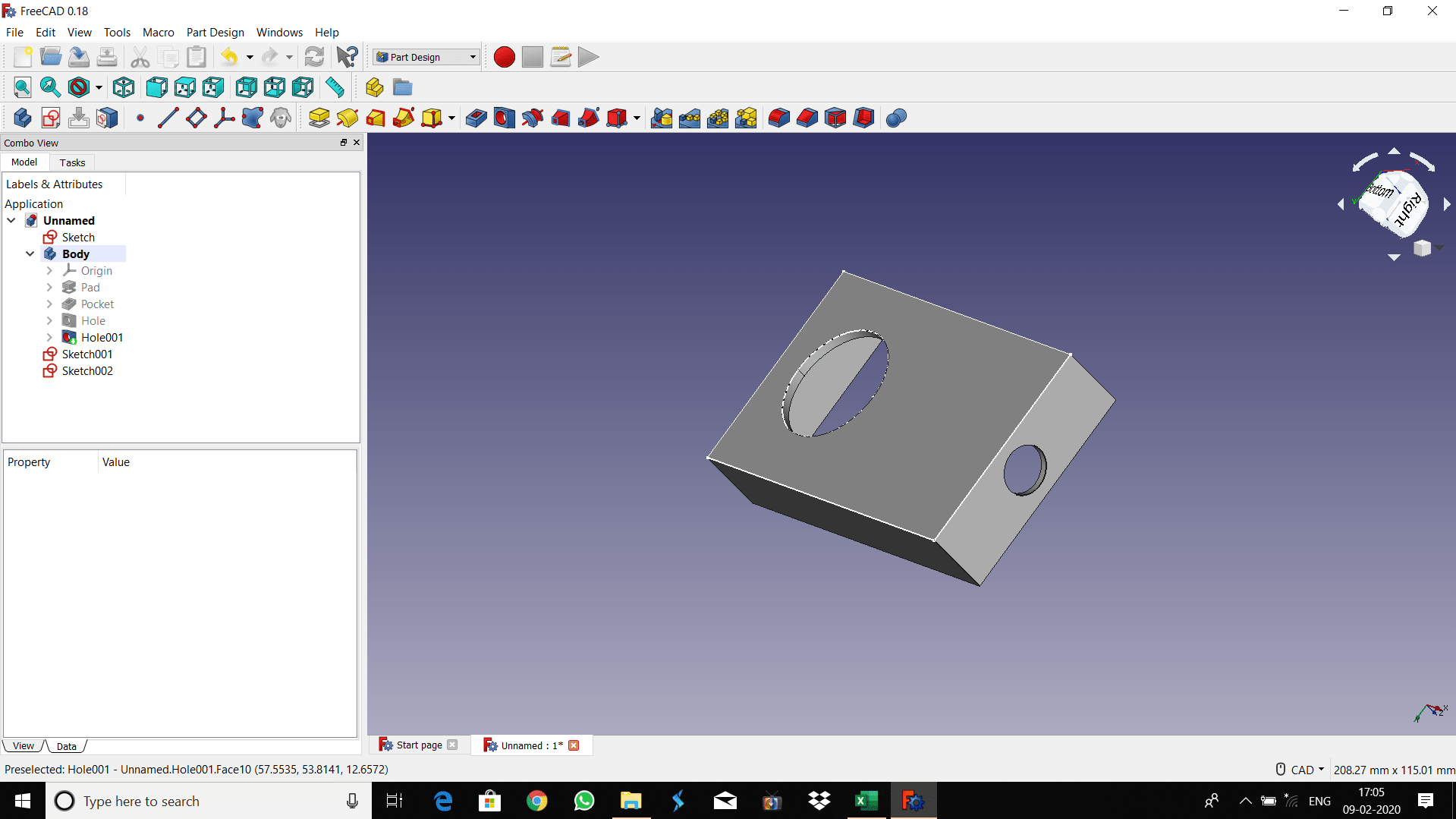
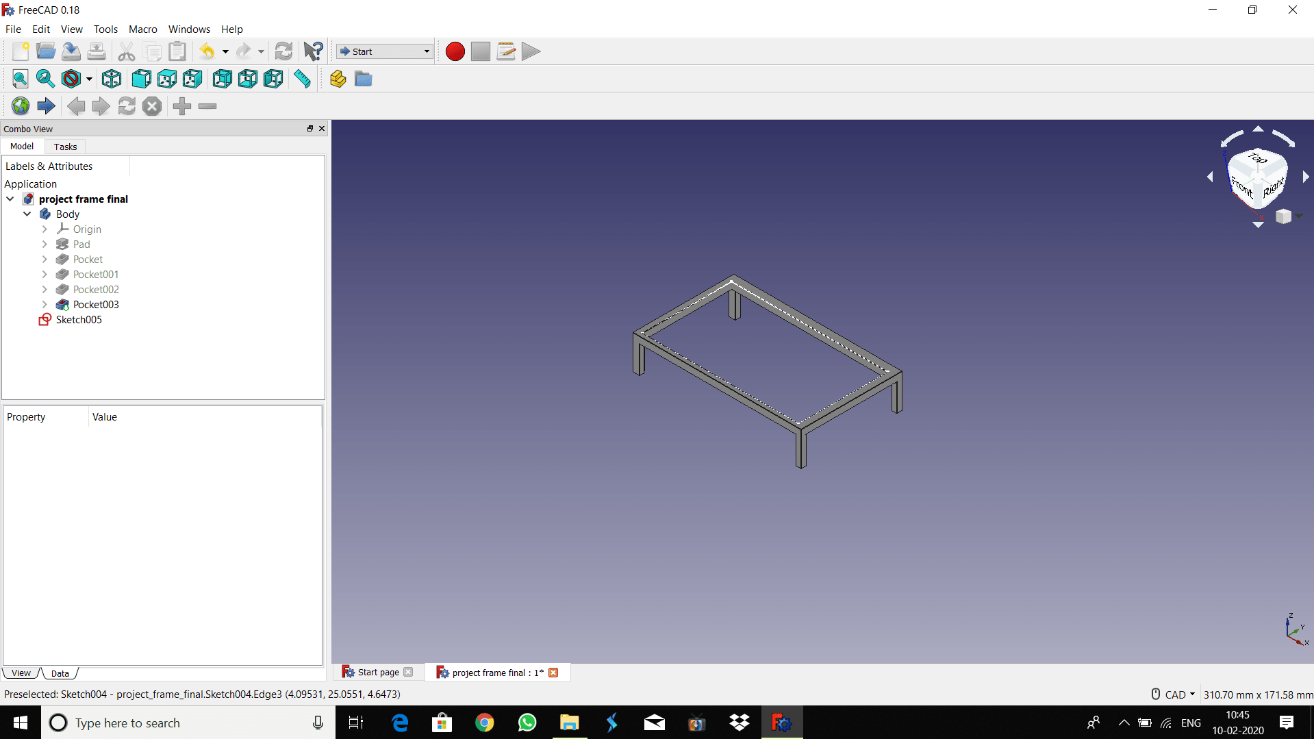
The following image shows the shape of M.S. frame required for project
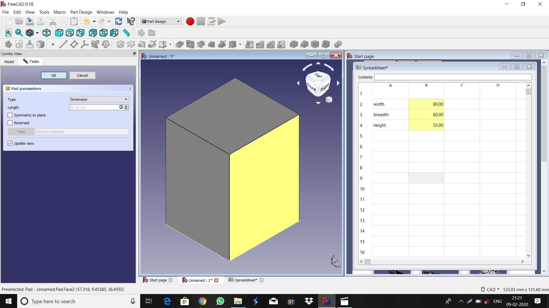
The parametric design using spredsheet is created in FreeCAD which shown in image below
2. Solidworks Software
The SOLIDWORKS CAD software is used for mechanical design automation application that lets
designers quickly sketch out ideas, experiment with features and dimensions, and produce models and detailed drawings.
SolidWorks allows users to create, simulate, publish, and manage 3D models. The technology intends
to make engineering processes more efficient with tools for conceptual design, product layout, strength and dynamics analysis, and more.
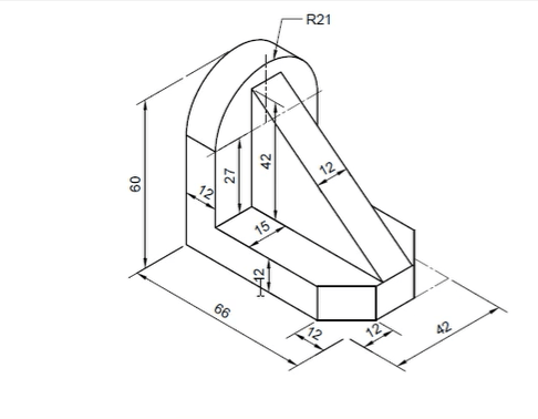
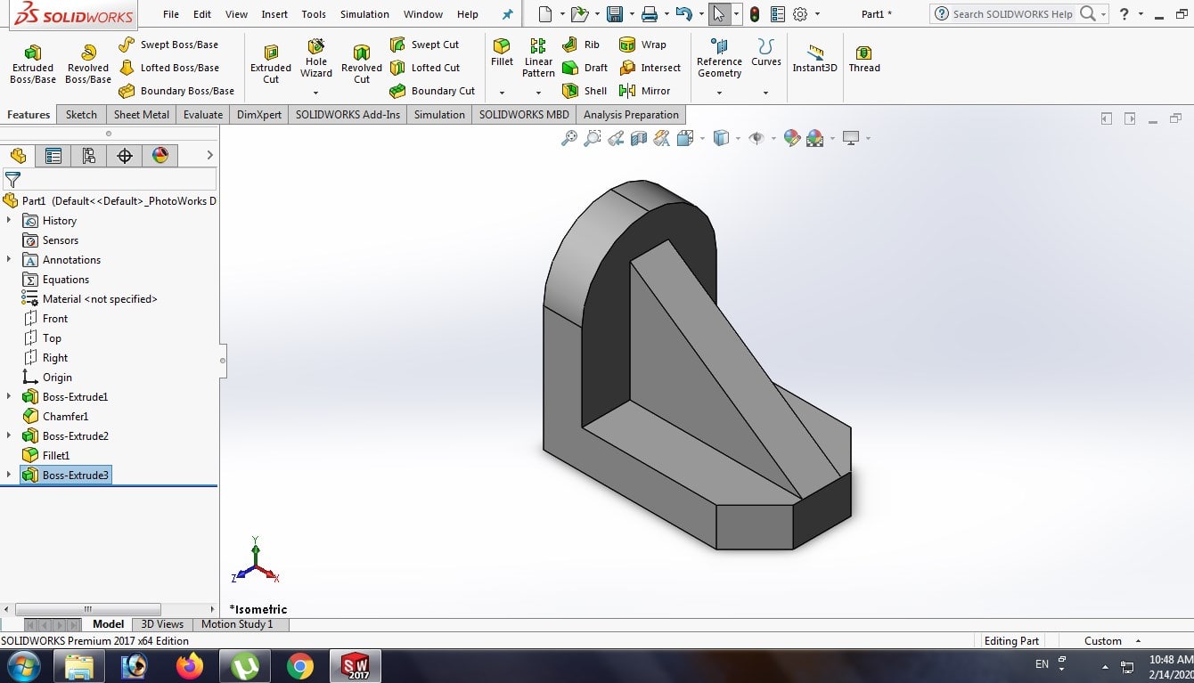
Here i have tried to develop 3D model from the given isometric sketch.
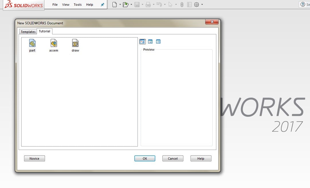
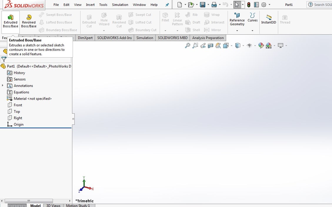
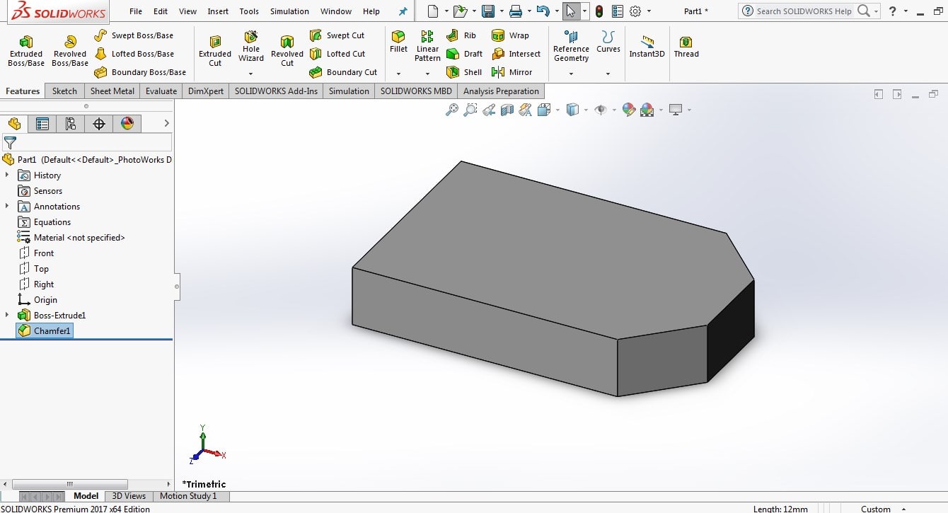
So first open the SOLIDWORKS>click on New>three menu open 1.Part 2. Assembly 3.Drawing>click on Part Menu
click on Extruded Boss/Base> select the plane.
Draw the reactangle>give the dimension by using smart dimension command.
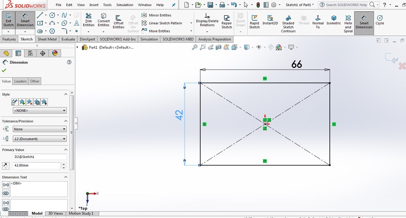
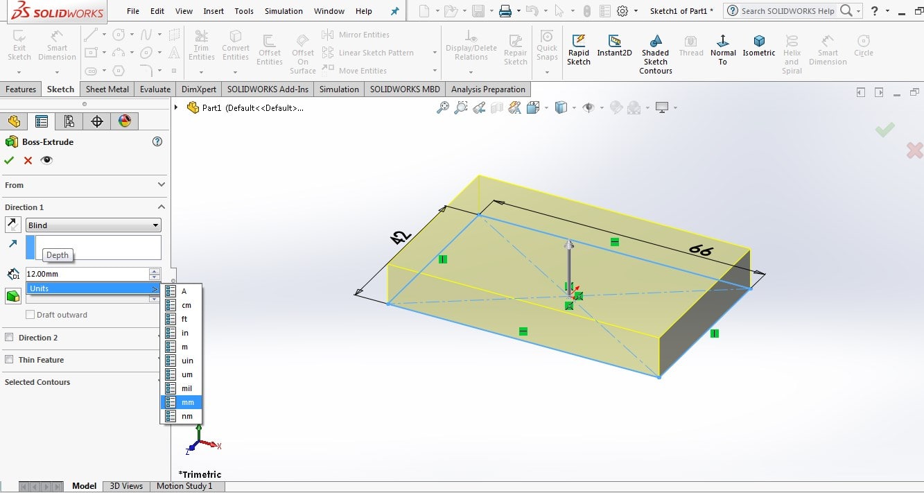
Then press ok>esc> then 3D model is created>put the required height to object>press ok
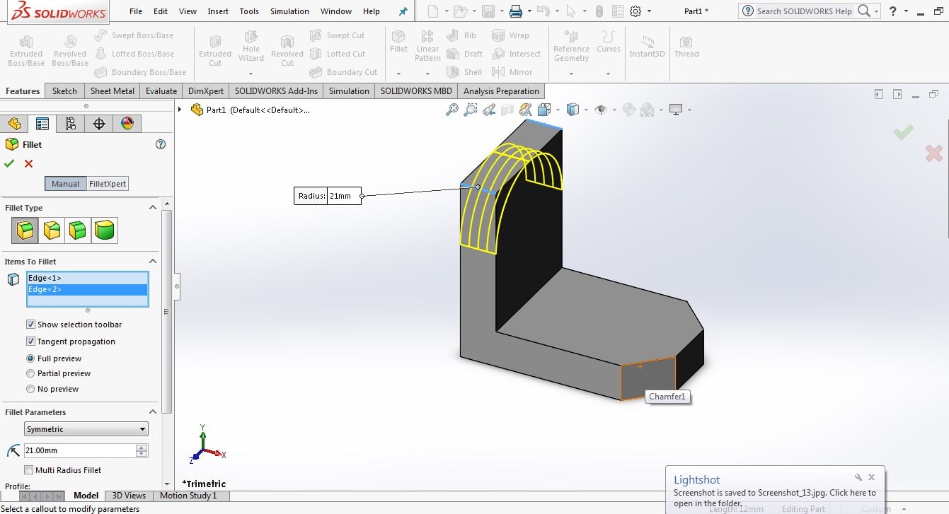
Then click om chmafer>select the edge>put the distant of chamfer
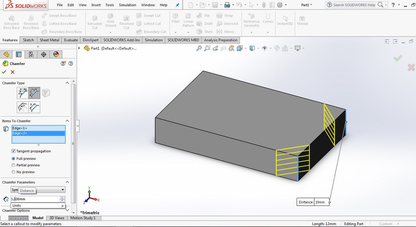
Then press ok>chamfer will created like this
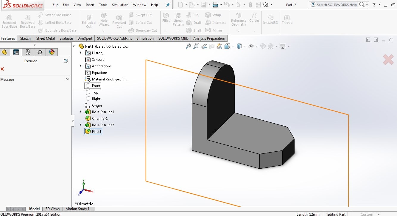
Now we have to draw a vertical plate with given dimension. so again press on Extruded Boss/Base>select surface>draw reactangle by using corner reactangle>give the dimension by using smart dimension.
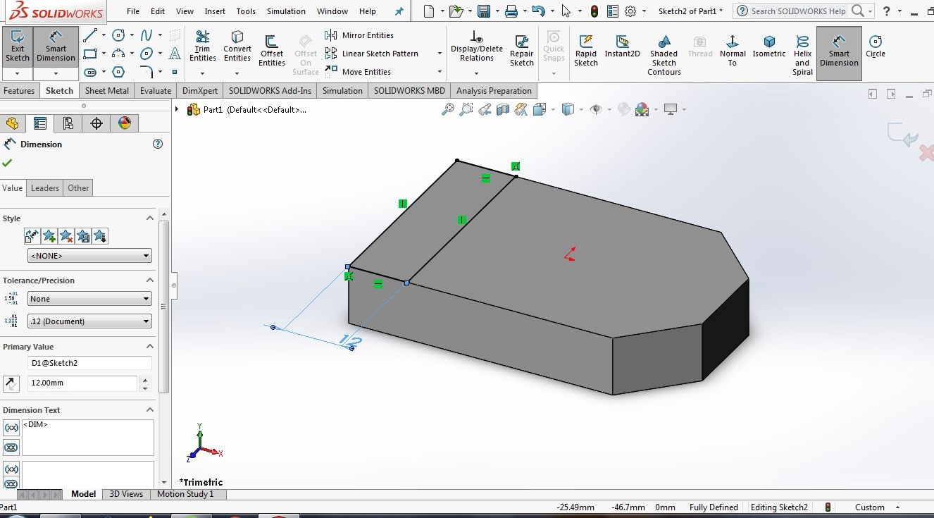
press ok> the object will created like this>put the required height
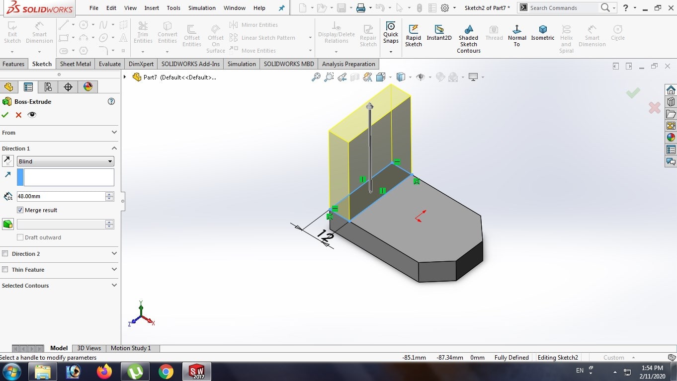
Now here we required fillet of 21 mm radius. so click on Fillet>select constant radius to left>select edge> put the value of radius>press ok>object will created like this
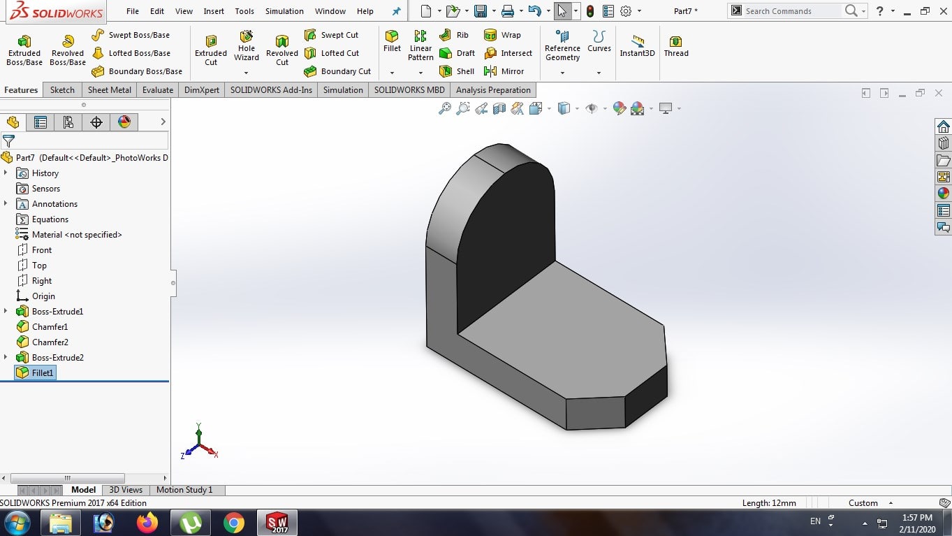
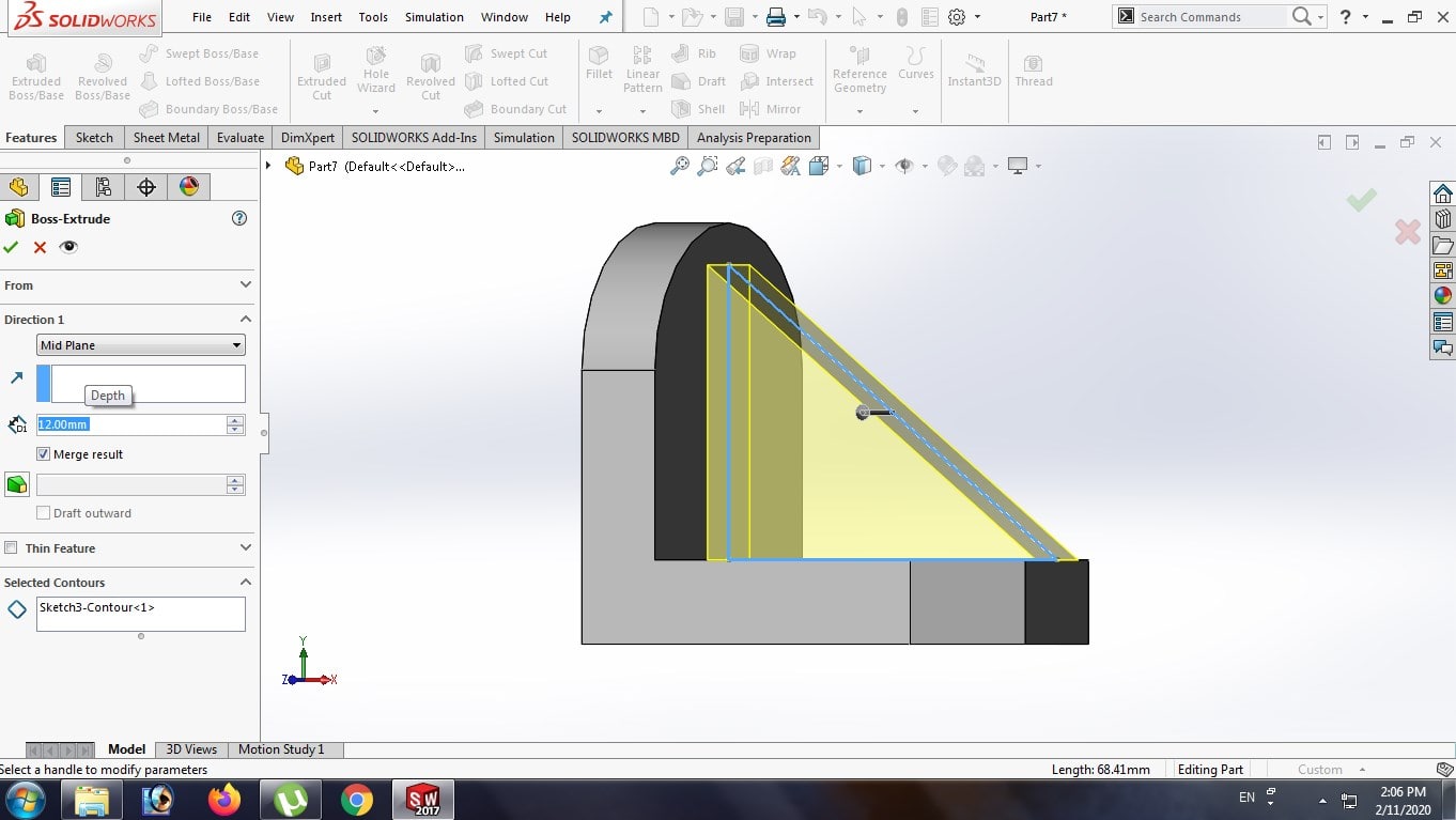
now we have draw a rib>so again select Extruded Boss/Base>select plane>draw a traingle>press ok
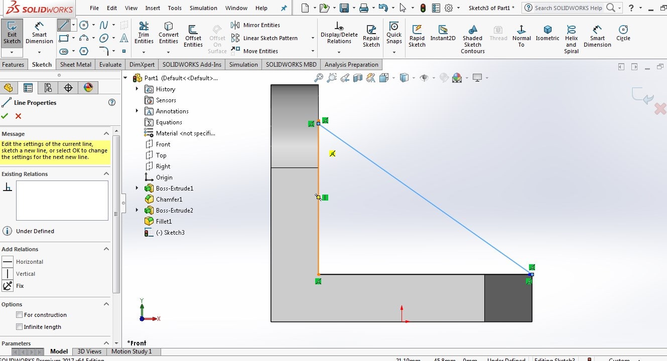
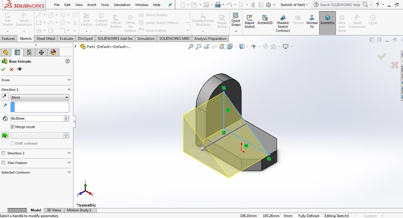
select the direction>mid plane>put the value of width of rib>press ok>final object will be created
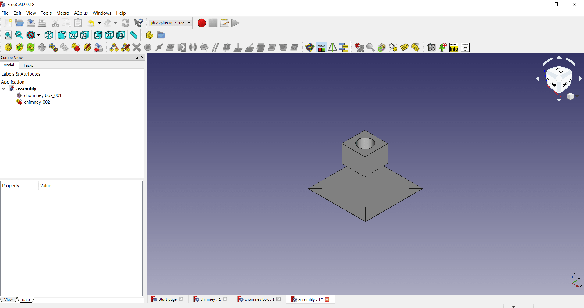
Assembly of Part
For the assembly of part, I have used FreeCAD software, here i tried to assemble
two parts of my second idea of project i.e. kitchen chemney.
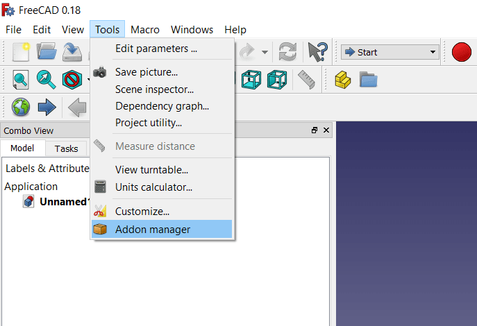
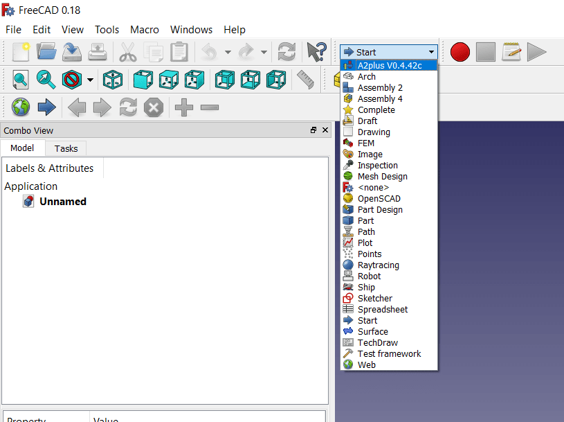
But when i see in workbench, ther is no workbench available for assembly, so it is required to add this extension file in Freecad.
Open Tools menu> Addon manager
Different workbench will get open, then click on A2plus> install> after installtion we get following message
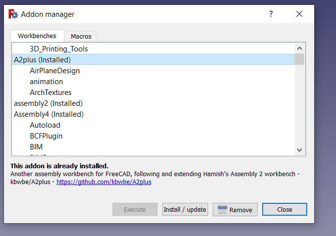
After installtion, restart the FreeCAD software, now A2plus is added in my dropdown menu, now click on this and create new file
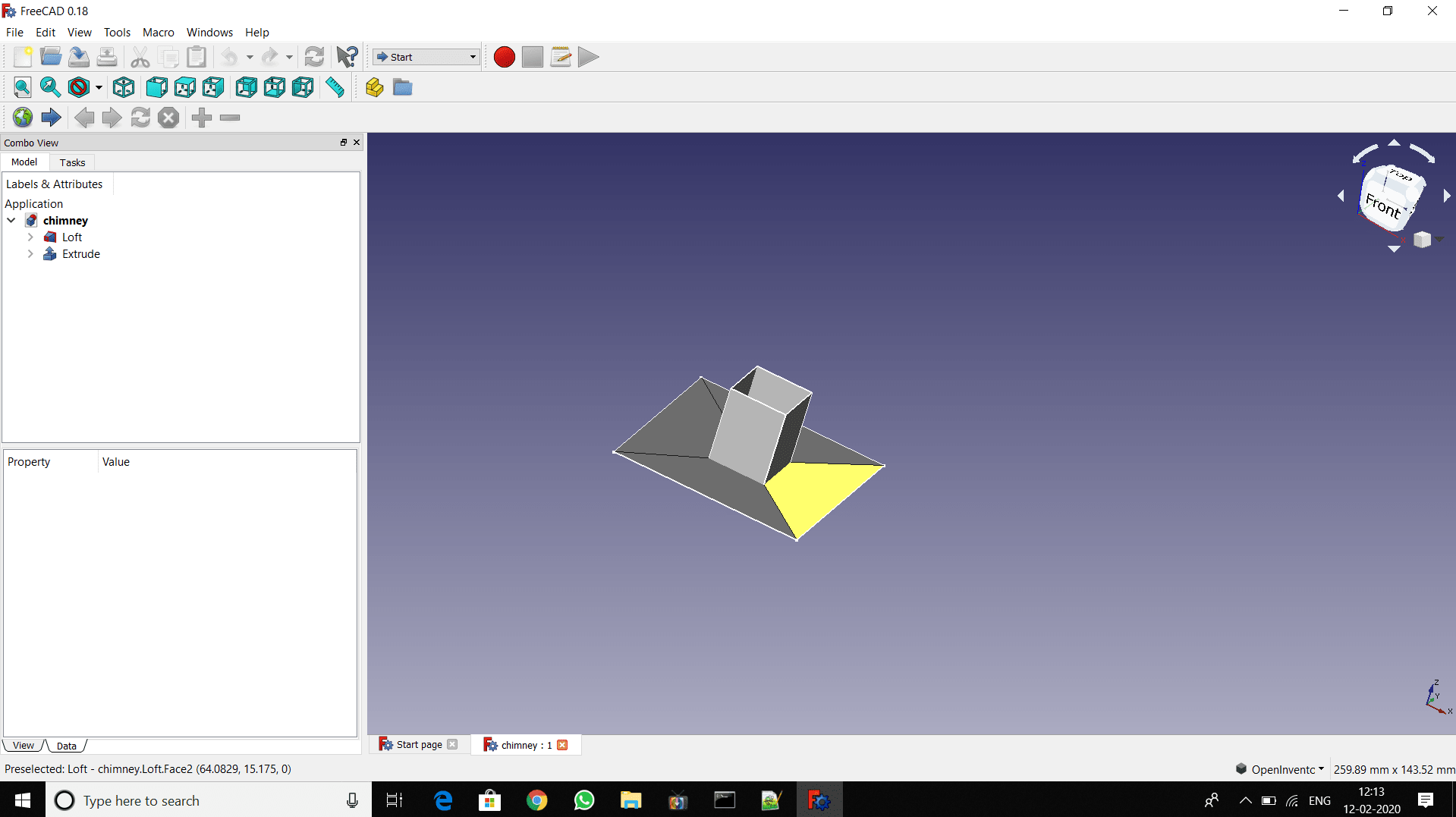
The first part of assembly
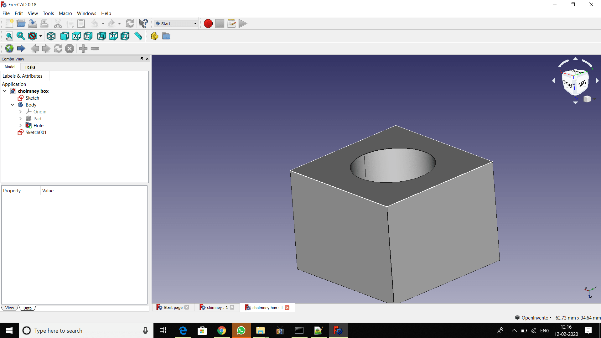
The second part of assembly
Now open the different file (i.e.part) that we have to assemble, by clicking on file menu. click on new file, select workbench A2plus, save the file and then import the part
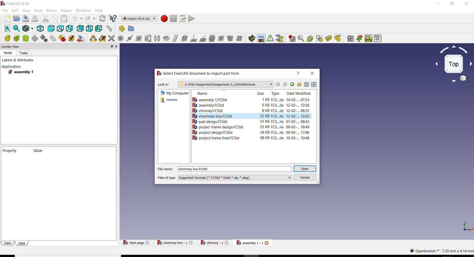
Now by right click, there is navigation style>CAD, so we can adjust the part, then assmble the part,the final assembly in FreeCAD is like this
What i learn?
1. Now I am able to draw and edit the Raster 2D images by using KRITA and GIMP.
2. GIMP is very comfortable for editing digital or photo/image/graphics. It is a free alternative to Photoshop.
Gimp has its roots more deeply rooted in that territory.
3. KRITA is more art (as in drawing, painting, etc.) focused. The layout is much less complex in KRITA compared to GIMP.
KRITA is comfortable for art related purposes, such as making comics, digital paintings, etc.
4. In short, think 1. GIMP- photography/image/graphic editing.2. KRITA- Comics/manga/drawings/paintings.
5. For Vector 2D design I have used Inkscape, FreeCAD and CorelDRAW software. Inkscape is free and open-source vector graphics
software that allows us to craft a range of graphic design such as logo, icon, illustrator, web graphics, and so on.
FreeCAD is also the opensource software. CorelDraw is a vectors graphics application by the Corel Corporation. It is commercial software. I feel more comfortable in Inkscape and FreeCAD.
6. For 3D design, I tried FreeCAD and Solidwork. FreeCAD is open source and Solidwork is commercial software.
FreeCAD is somewhat typical but as we make the practice, it will get easy. Solidwork is easier to operate,
the visual effect is also very best.
7. I feel more confirmable in FreeCAD now.
Download my original file here
Go to the top
Back
Assignment 4: Computer Controlled Cutting
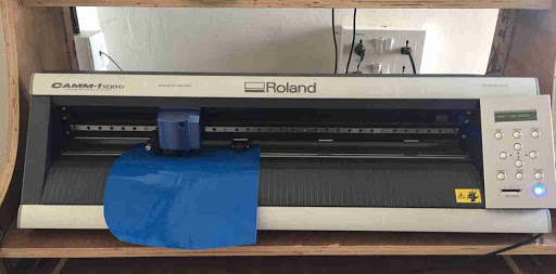
The Computer controlled machining is a subtractive manufacturing process which typically employs computerized controls and machine tools to remove layers of material from a stock piece—known as the blank or workpiece—and produces a custom-designed part..

Fab Academy Course on Digital Fabrication by Nikhilkumar More is licensed under a Creative Commons Attribution-NonCommercial 4.0 International License.
Based on a work at http://fabacademy.org/2020/labs/vigyanashram/students/nikhilkumar-more/.
Permissions beyond the scope of this license may be available at http://fabacademy.org/2020/labs/vigyanashram/students/nikhilkumar-more//contact.html