Electronic Production
Week Task
group assignment: characterize the design rules for your PCB production process
individual assignment: make an in-circuit programmer by milling and stuffing the PCB, test it, then optionally try other PCB processes
Introduction
The PCB manufacturing process is very important for anyone involved in the electronics industry. Printed circuit boards,
PCBs, are very widely used as the basis for electronic circuits. Printed circuit boards are used to provide the mechanical basis on which the circuit can be built.
Accordingly virtually all circuits use printed circuit boards and they are designed and used in quantities of millions.
In this week we have study the PCB production processes then we have to make an in-circuit programmer by milling and stuffing the PCB. After this we have to test this PCB.
The machine available for PCB milling in our Fab Lab has folowing specification:
Manufacturer: Roland
Model: SRM-20
Specifications: 203x152x60 mm, 1800 mm/min, 0.001 mm/step, 7,000 RPM
Applications: Precision three-axis machining, including PCBs down to 0.25 mm feature size, and machineable wax to make tooling for molding and casting
Group Assignment
In group assignment, the task for this week is to characterize the design rules for PCB production process.
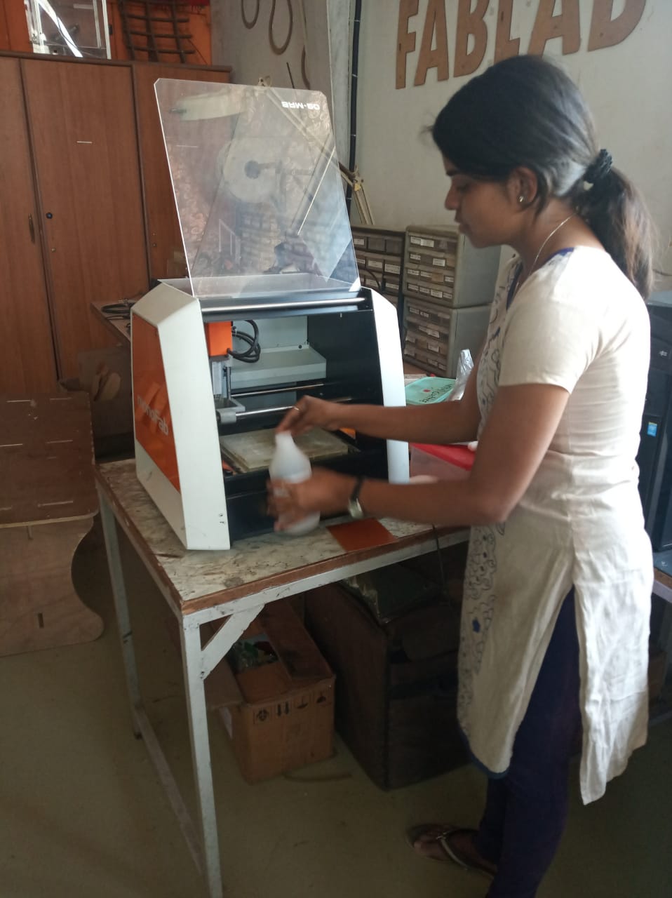
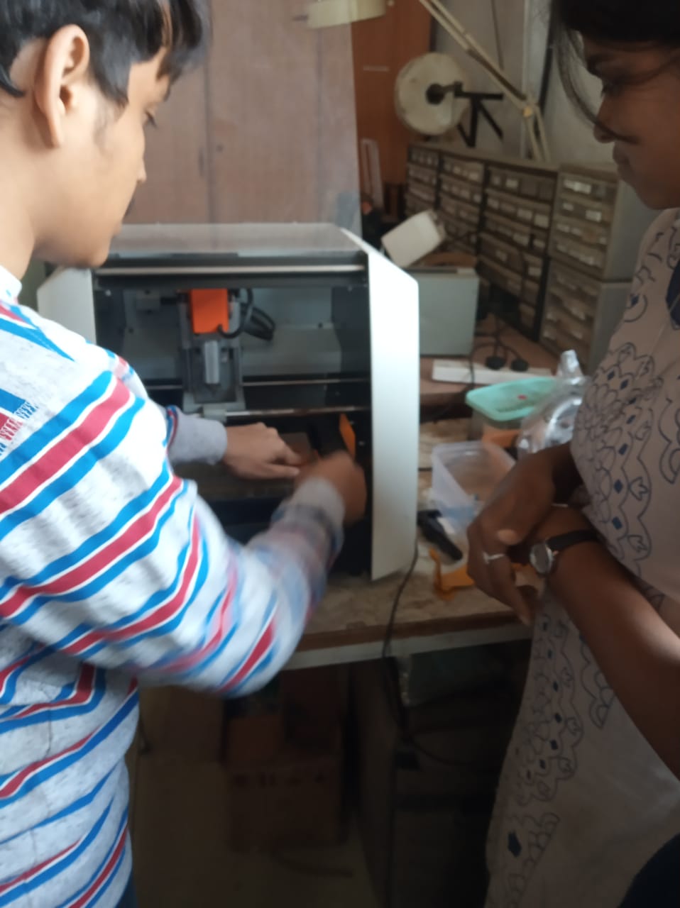
So we five member in group, trying to machining of PCB usign SRM-20 i.e. PCB milling machine available in our Fab Lab. So,lets see how we develop the PCB.
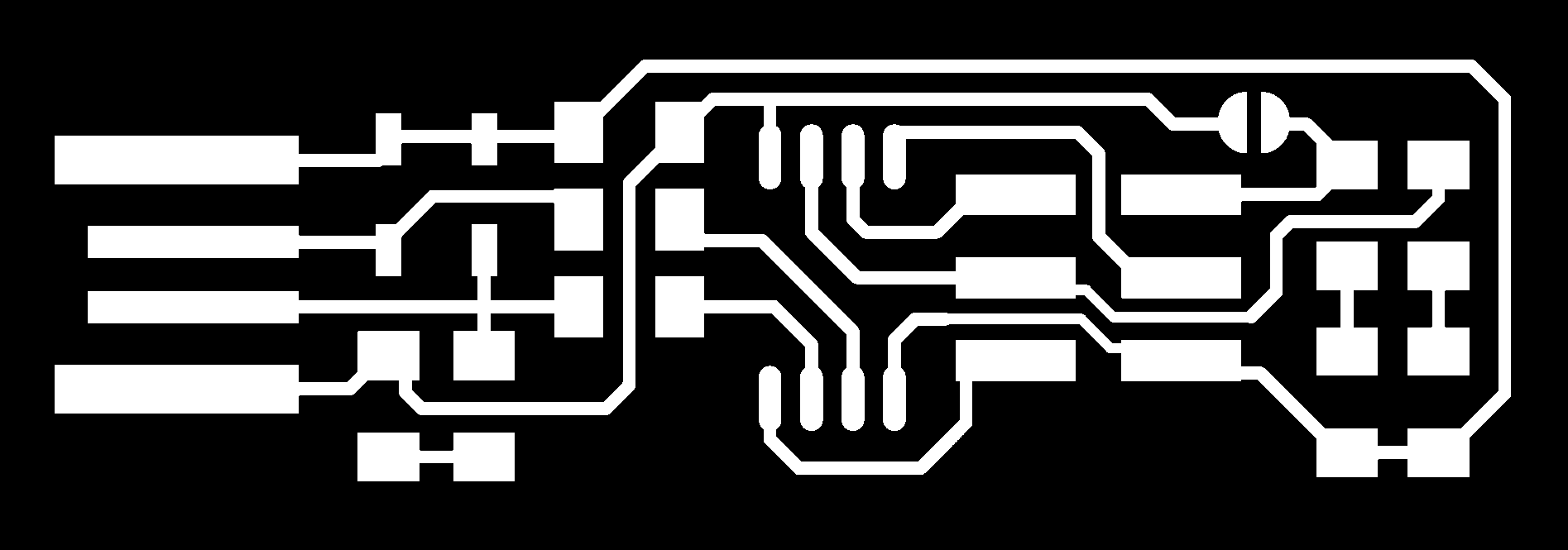
The given png image for trace and cut is shown below.

The file is converted into rml formatt by using the modes.How the modes are used, it is given in Individual
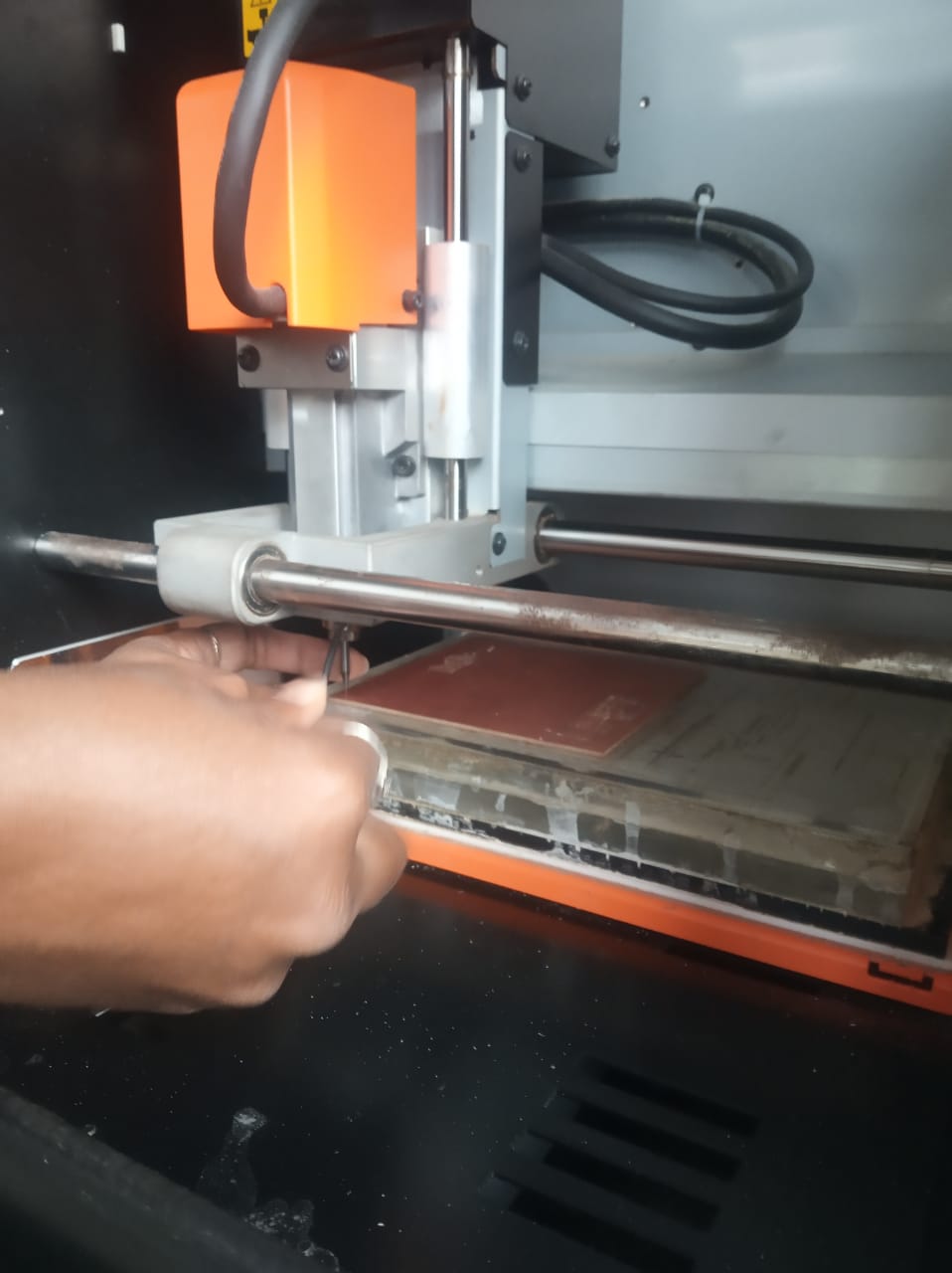
Assignment. For PCB trace operation we are use 1/64inch drill bit. The machine bed is cleaned by Acetone chemical.Then the PCB is pasted on bed of machine and started the machining.
After tracing next operation is cutting. The cutting file is selected for this opeartion. Drill bit changes, now 1/32 inch drill bit is used and cuted the PCB
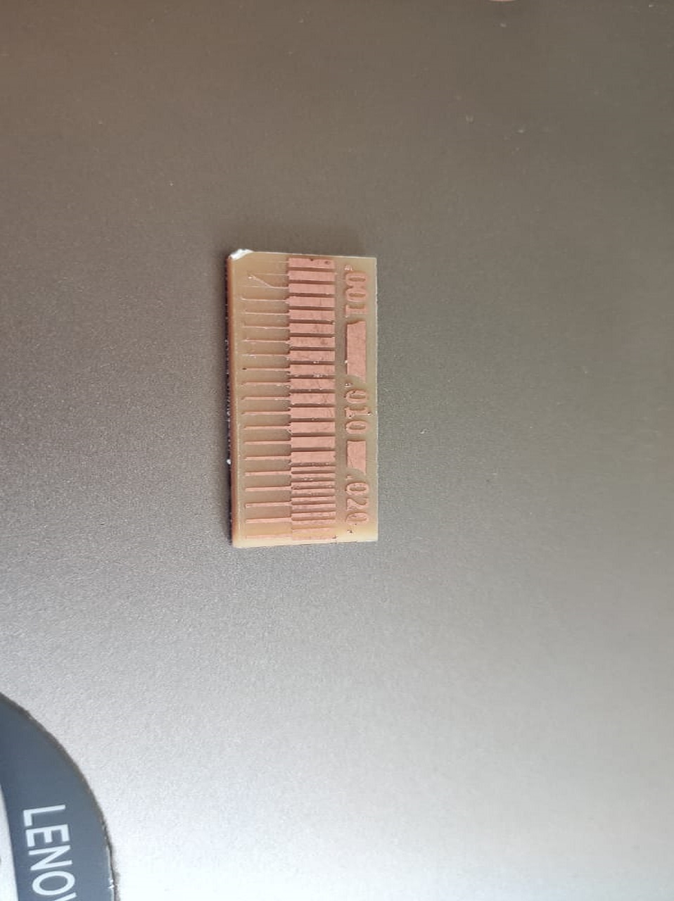
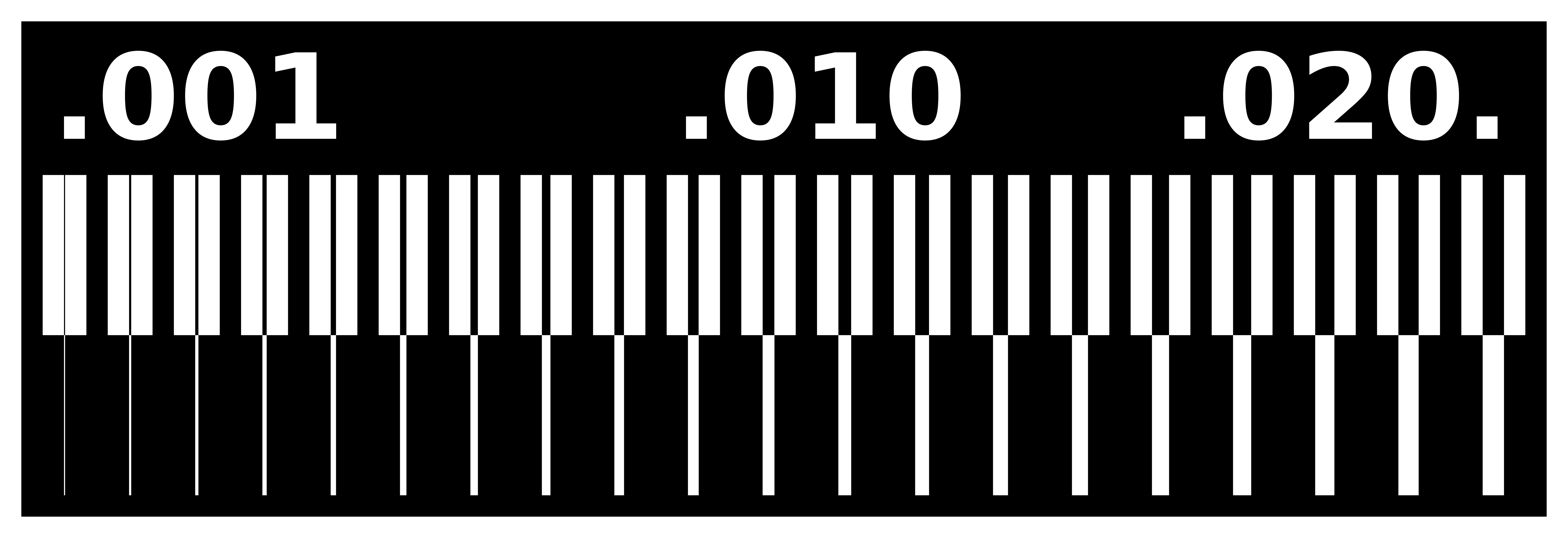
Here the line test is conducted between the 0.001 mil to 0.020 mil. The line widths around .001 mil are bit risky to mill, but the ones nearer to 0.01 mil are quite good and line around 0.020 are good to machining.
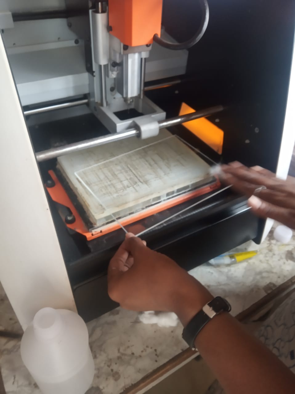
When you are fitting the board with double-side tape to the wooden surface be sure to press it really strongly! Sometimes it’s a good practice to clean the wooden plate from rests of the previous tapes, or even hardly visible glue. Due to uneven pasting, the bubble are form
to the back of PCB material, it will affect to machining, sometiomes it fails to machining also. Also its also need to check the bed level, its also affect on machining. The bed should be perfectly
horizontal. So this is our obseravation from Group Assignment
Click here for details about 4-Week Group Assignment
Individual Assignment
In this assignment, we have to make an in-circuit programmer by milling and stuffing the PCB, test it, then optionally try other PCB processes. So lets discuss, how the ISP is developed.
PCB Fabrication
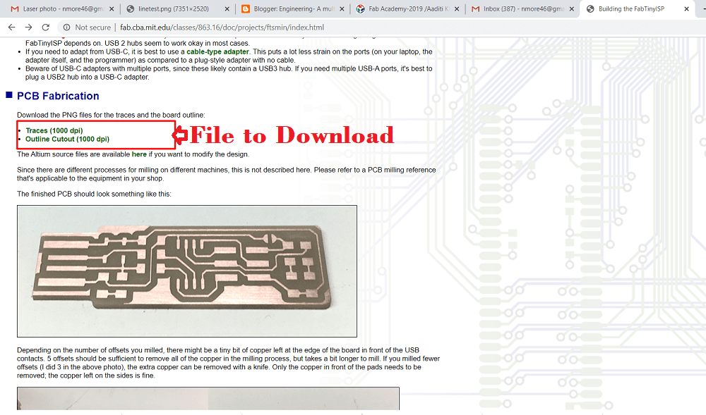
In this assignment, the design of the PCB is given by Fab Academy. The design is available in png formatt on the given website. I downloaded the file from here

Modes Selection
The machine software can read only rml file. so we used different modes to converts the file into rml formatt. This
modes are develop by Fab Academy. It is used for all cutting machine in Fab Lab. Lets see how we can used it step by step.
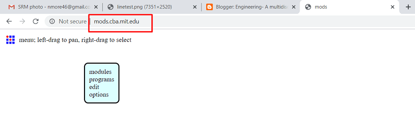
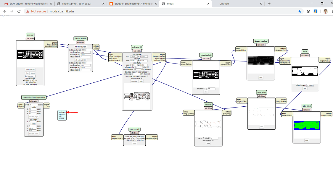
Step 1: Go through the following website for to open the modes
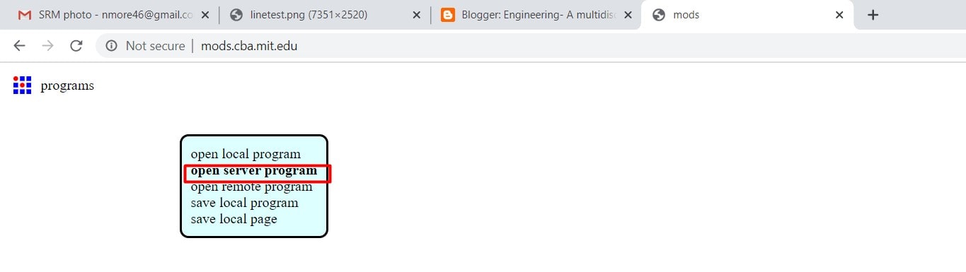
Step 2:Select the programm>open server programm
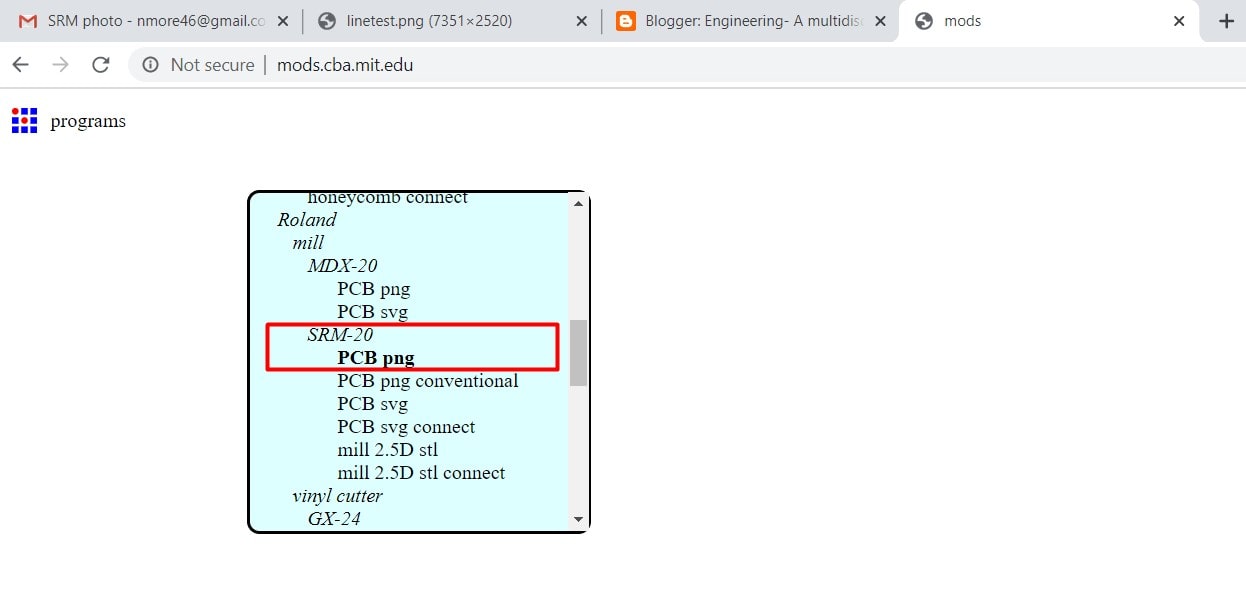
Step 3:Select the type of machine>the design file formatt
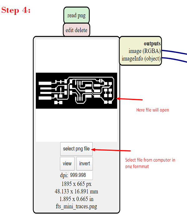
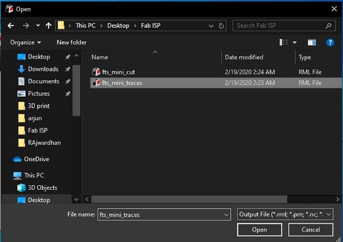
Step 4:Select the png file from our computer
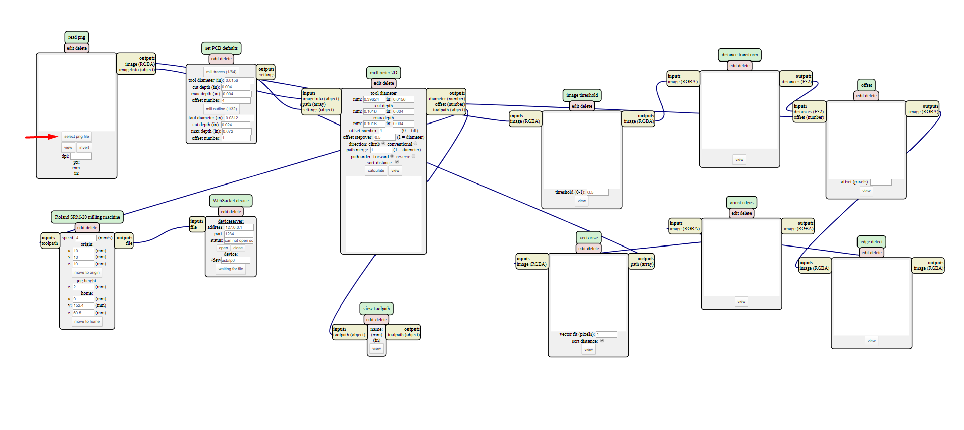
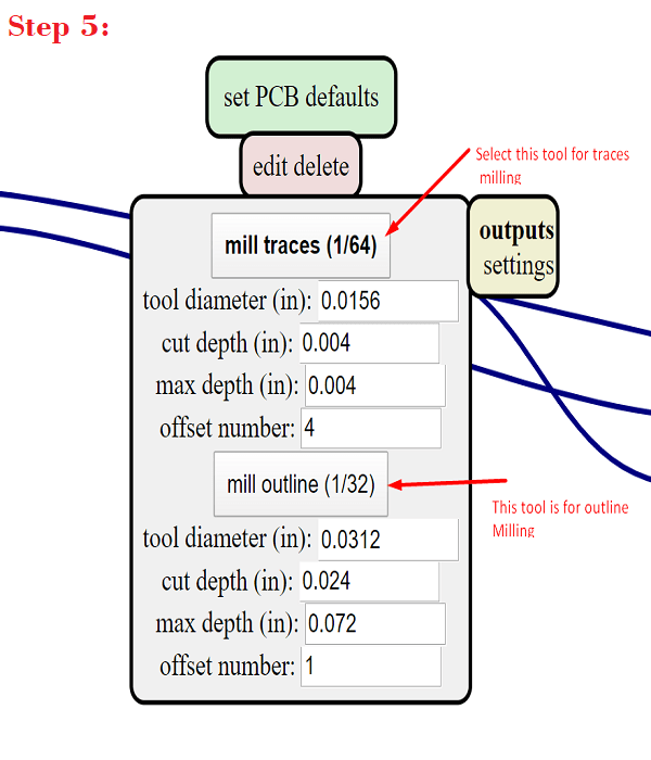
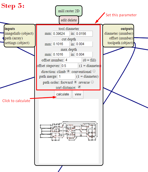
Step 5:Select the tool> for trace operation, tool is 1/64 inch>then click on calculate opetion.
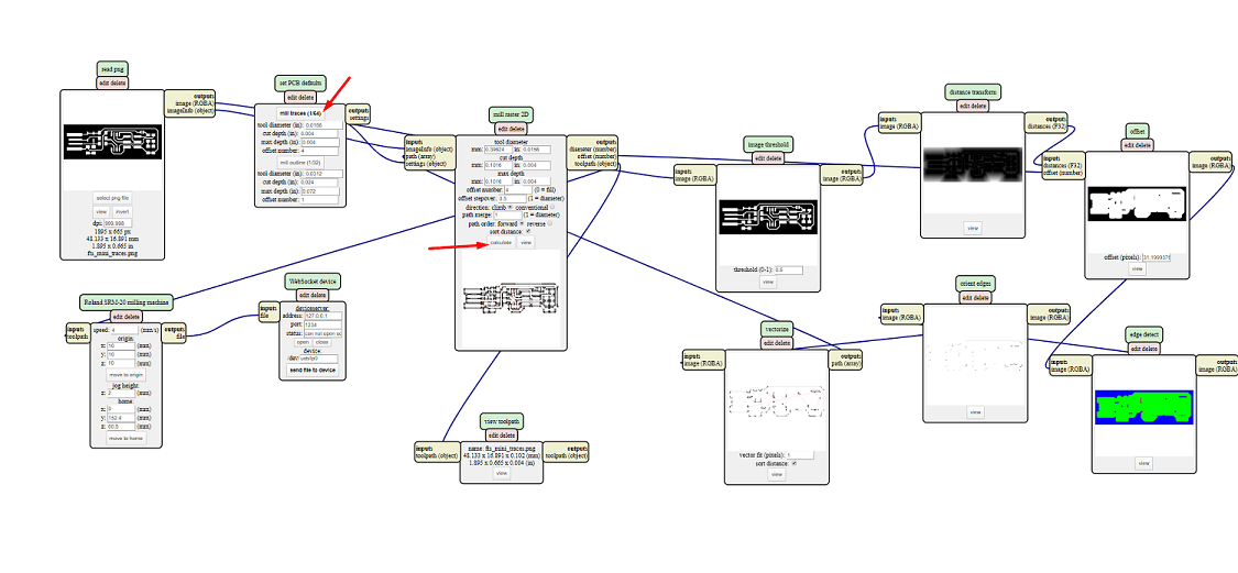
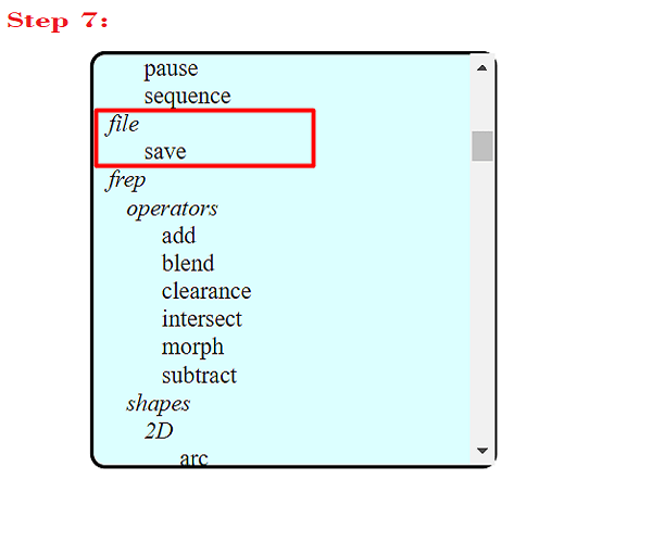
Step6: Now we have to save the file in rml formatt>for this purpose add the new module in the programm i.e. file>save
Step 7: Then click on file>save module for to save the rml file.
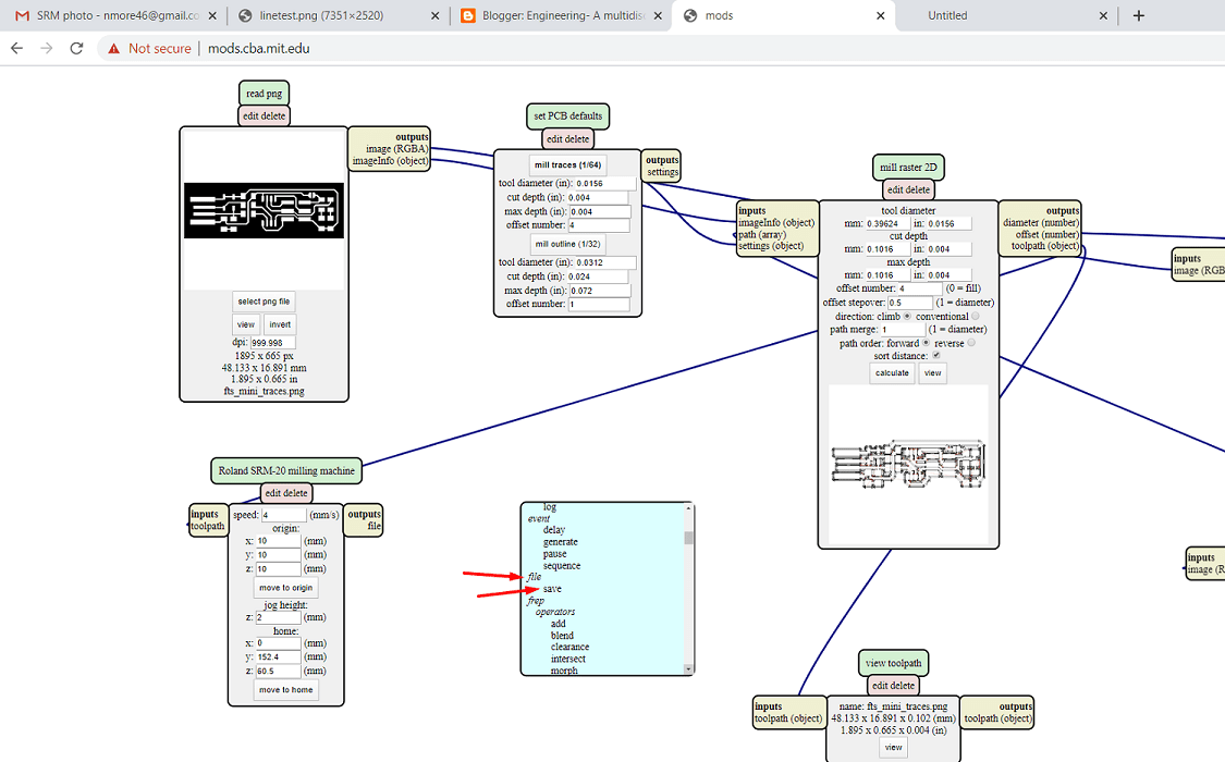
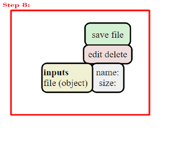
Step 8: After clicking on file module> the following module will get open.
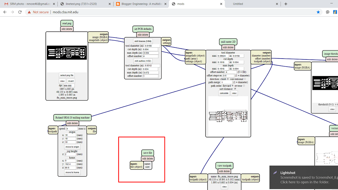
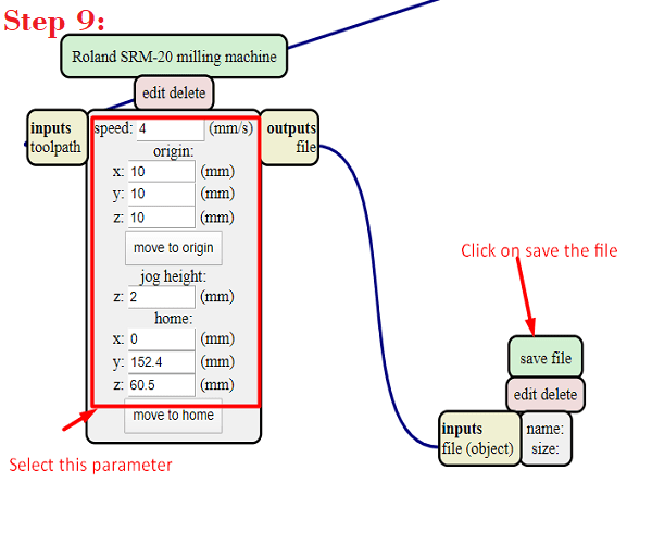
Step9: Then connect the output of milling machine to input of file>also set the origin of tool i.e. x,y,z direction,jog height, speed etc.
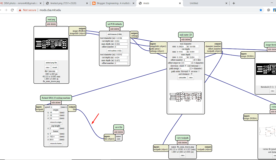
Step 10: Then click on Save the file>file will get download
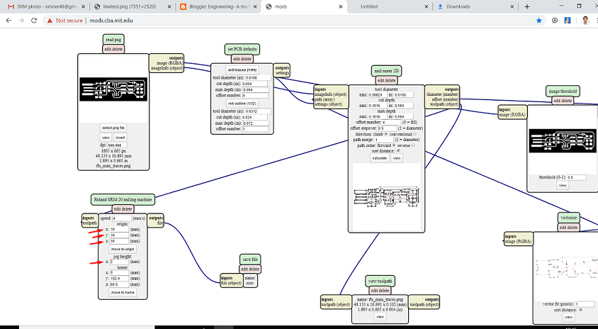
The zoom image of above step is shown below:
PCB Machining
On machine we have to do the two operation, first one is to make trace on PCB and second one is cutting of PCB.Fab academy
also provide two file to us. One for trace and one for cut.so in modes we have converts this two files in rml formatt. But one thing is important. There
are two different tool is used for this. 1/64 inch drill bit tool is used for trace and 1/32 inch tool is used for cut.So during modes select this tools also. So
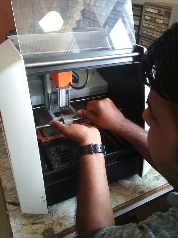
firstly we are doing the trace operation and then cut operation. So attch the 1/32 inch drill bit to the machine. It is very carefull operation.Handle the bit very carefullu
because if the knife of the bit will get damage, then we have to replace the bit.so take care during this.
Material Used: FR-1, Tool Used: 1/64, 1/32 inch drill bit.
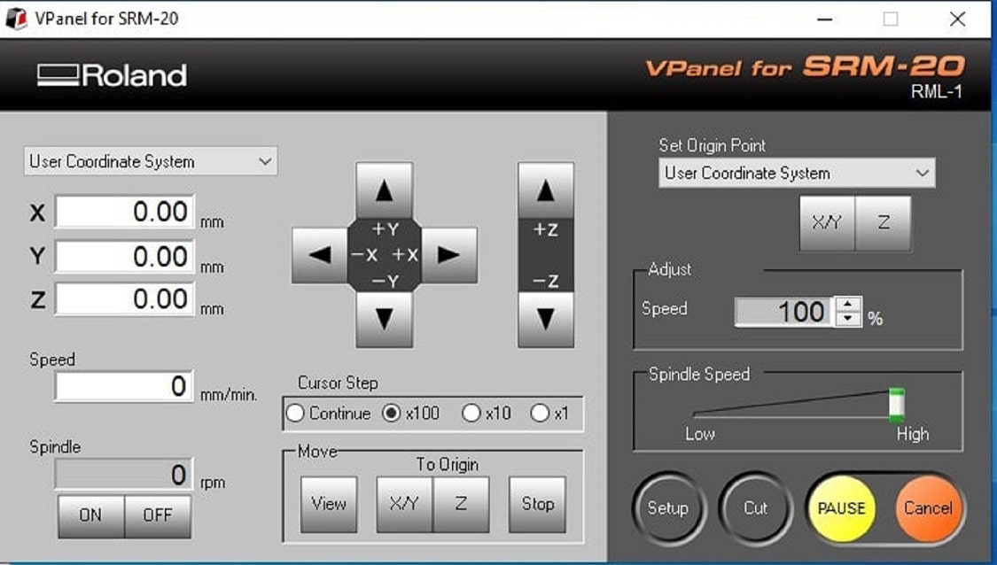
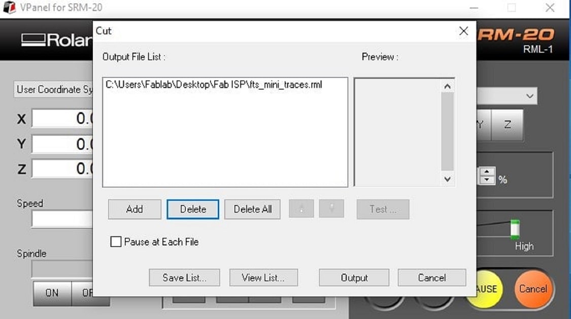
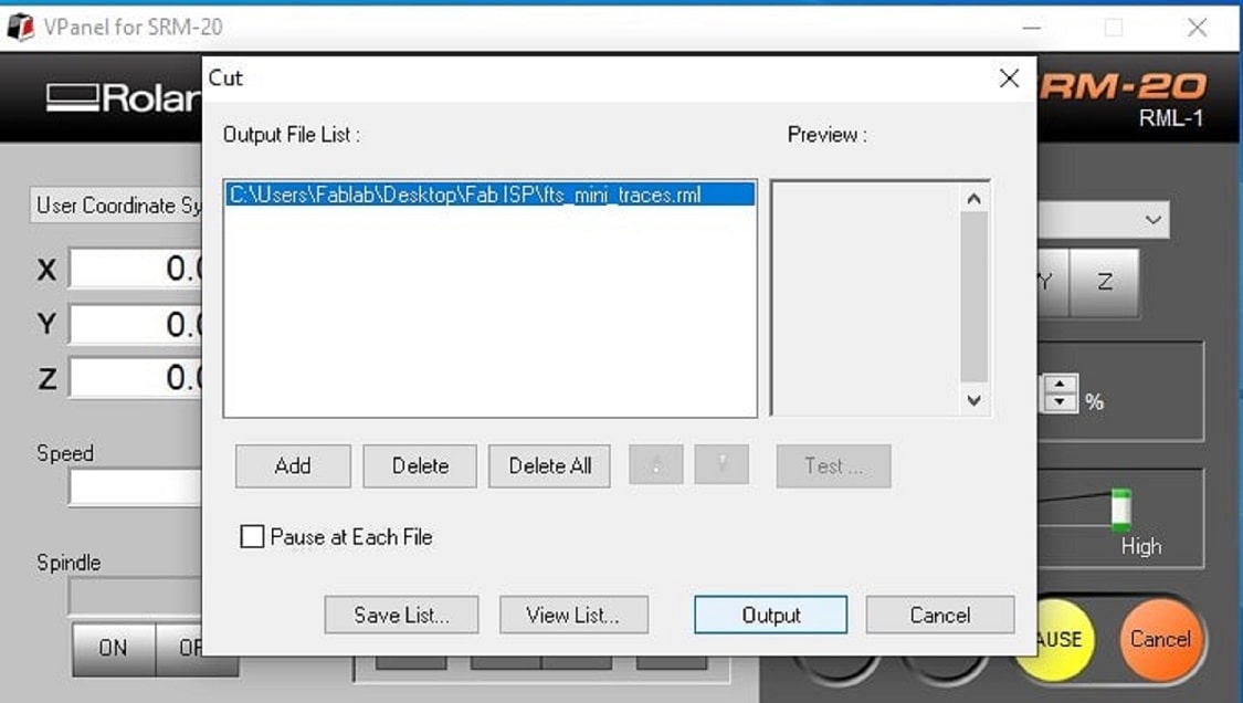
So now open the Computer which is connected to SRM-20 machine>open the V panel for SRM-20 software >select the X,Y and Z coordinates for tool>set the origin>select cut button>Add file>delect if any existing file is there>select output>trace operation will start
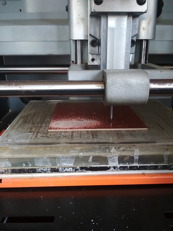
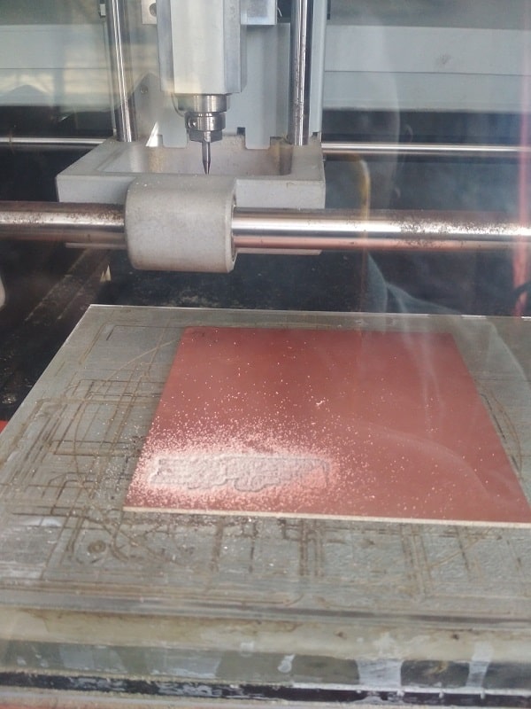
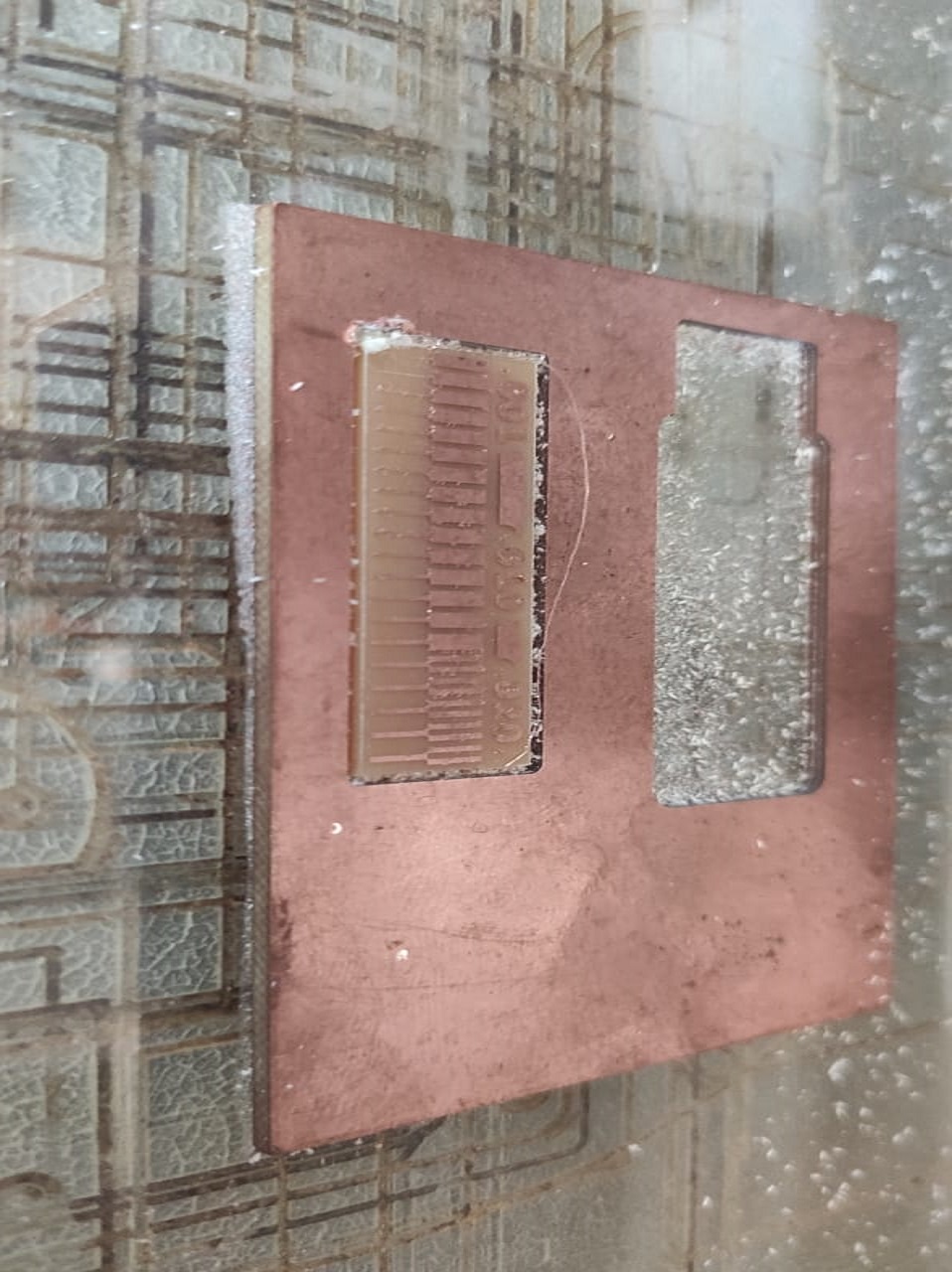
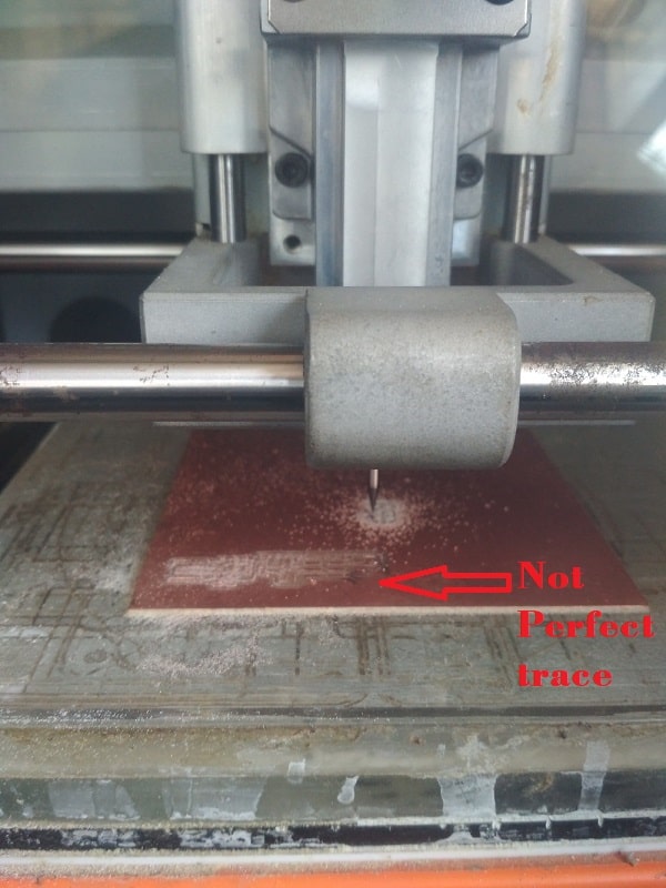
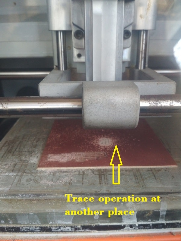
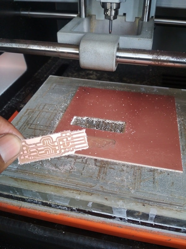
Trace operation is now finished, let's check the whether the operation is perfect or not? after cleaning the PCB, it is observe that, the trace is not perfect, i think there is bubble, below the PCB or bed is not completely flat. Lets change the position on PCB and try at another place.
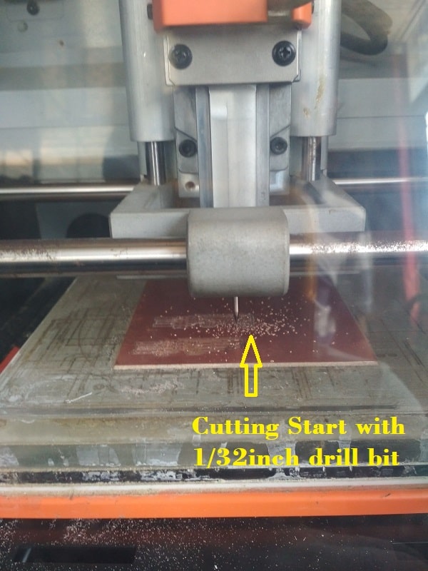
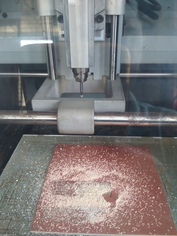
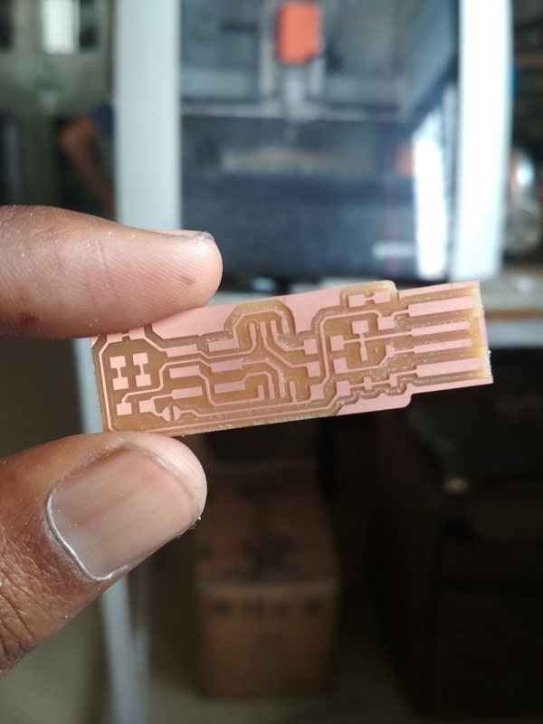
Now the trace operation is perfect>now lets move for cutting operation>change the bit>use 1/32 inch drill bit>select the another rml file for cut>start cutting
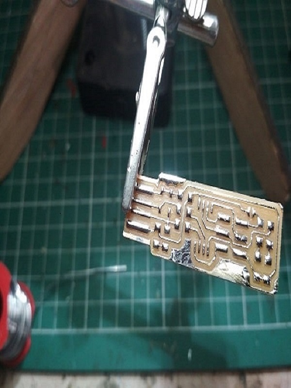
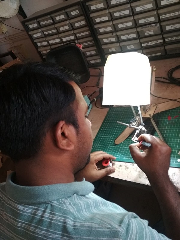
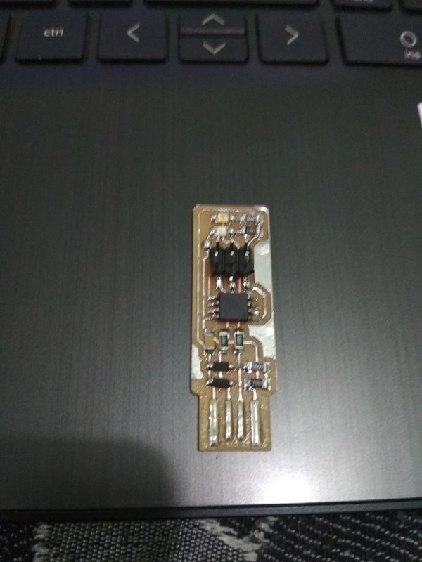
Assembling the PCB
After the machining, its time to component mounting, I have refer the image given Fab Academy, according to that, I have solder a component.
The following is list of component that i have solder:
1x ATtiny45 or ATtiny85
2x 1kΩ resistors
2x 499Ω resistors
2x 49Ω resistors
2x 3.3v zener diodes
1x red LED
1x green LED
1x 100nF capacitor
1x 2x3 pin header
Software Installation using Windows10
Fab Academy provides a instruction for software installation in PCB. The instruction is chategories according to operating system.
For group assignment, we use Linux operating system of center computer of our Fab Lab. But in my laptop, there is Windows OS, so for personal assignment, I tried Windows OS.
Linux is quite easy as compared to Windows.
so lets discusss what step i am following for this.
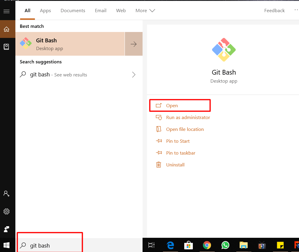
Step 1:Firstly its need to install Git, we have alredy Git Bash. so click on start menu,search "Git Bash" it will get open.
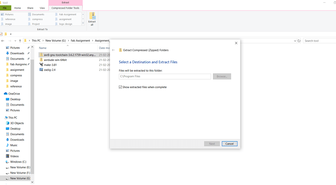
Step 2:Download the Atmel AVR Toolchain for Windows from Atmel's site and run the installer. Extract the file in C:\Program Files.
Step 3:Download Gnu Make and launch the installer.
Step 4:Download avrdude.Unzip the archive, and copy the archive inside to C:\Program Files.
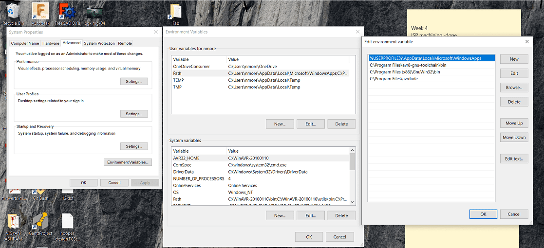
Step 5:Then go to the Start menu and search "Advanced System Settings". Under the Advanced tab, click the "Environment Variables" button.
Step 6:Under User variables, select "Path" and click the Edit button. If you don't already have a variable called "Path", click the New button to create it, enter "Path" without the name,
and fill out the value as described below.
The three values to add are:
C:\Program Files\avr8-gnu-toolchain\bin
C:\Program Files (x86)\GnuWin32\bin
C:\Program Files\avrdude
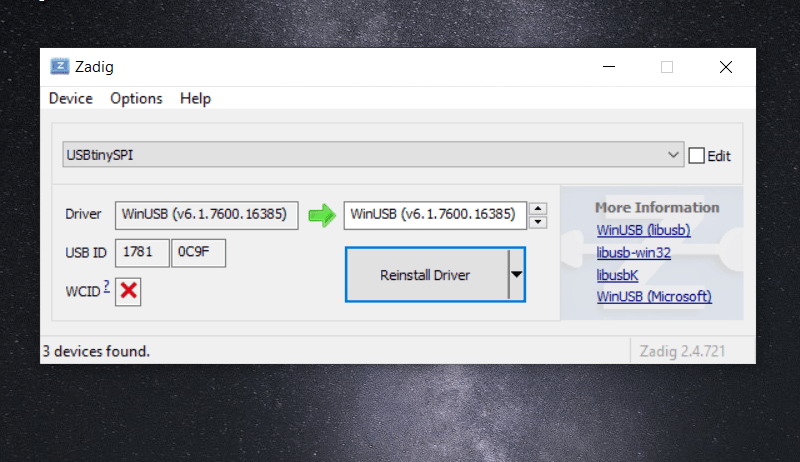
Step 7: Download Zadig and launch it. Plug in programmer to laptop, and select the "USBasp" device in the list. Download the driver for this.
Sanity Check
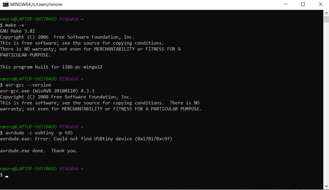
Now all software is installed, lets check whether all are working or not?open the "Git Bash" from Start Menu>apply the commande>type "make -v" and press enter>this command is OK.
Then in Git Bash type "avr-gcc --version" and press enter>ohh its also OK
Then connect the programmer to Laptop>Type avrdude -c usbtiny -p t45>press enter>Error:could not find USBtiny devise
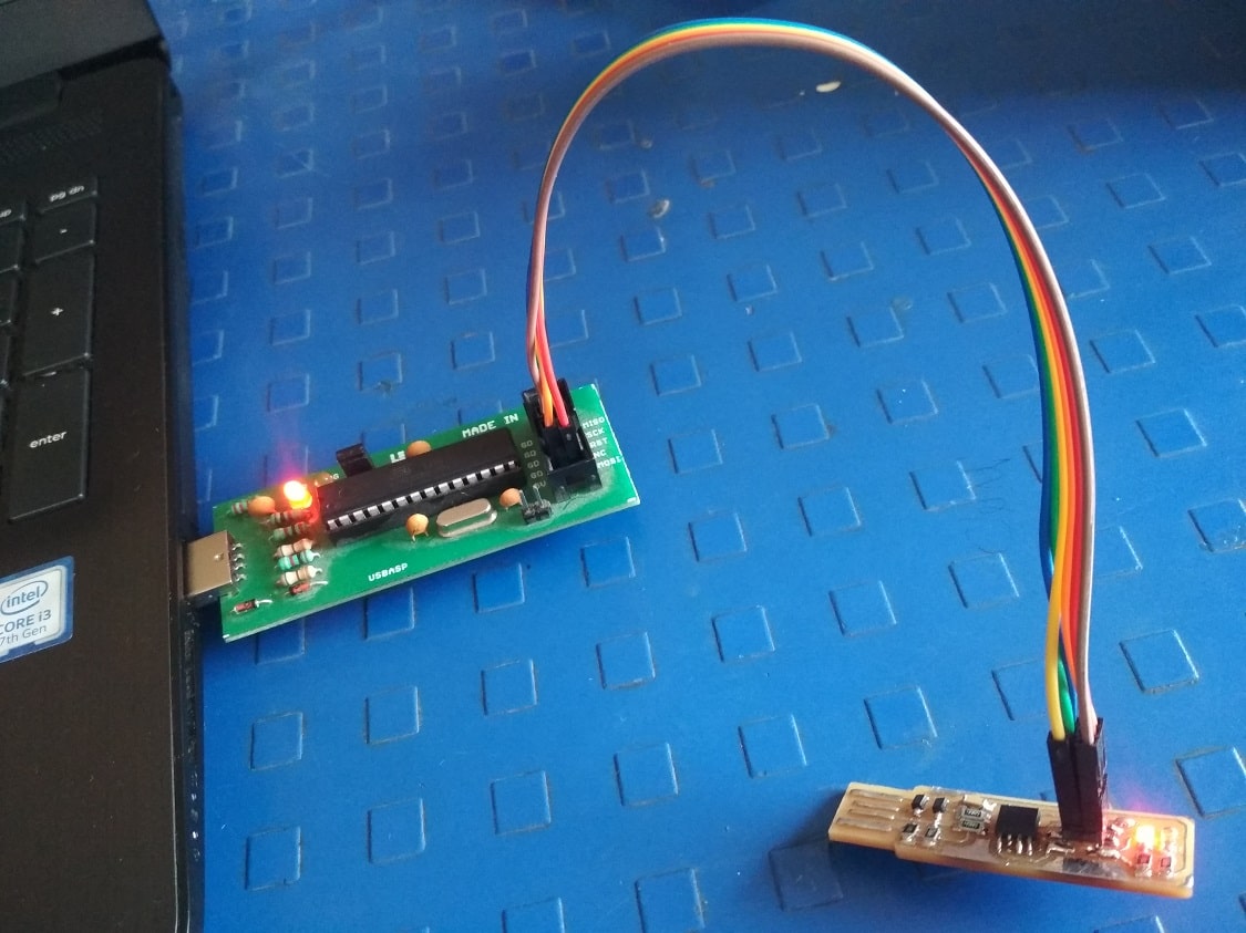
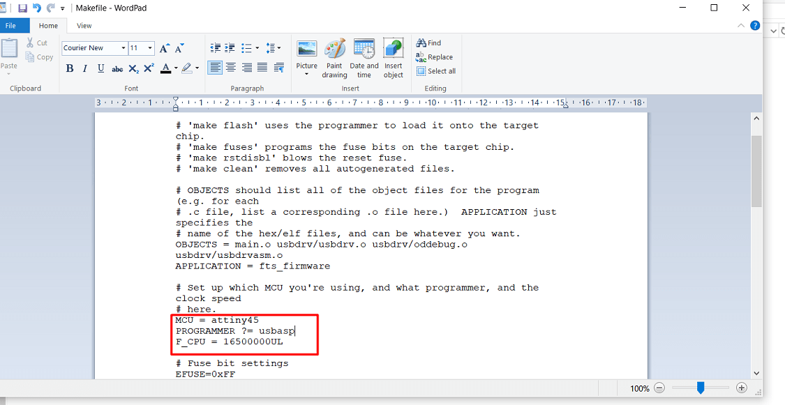
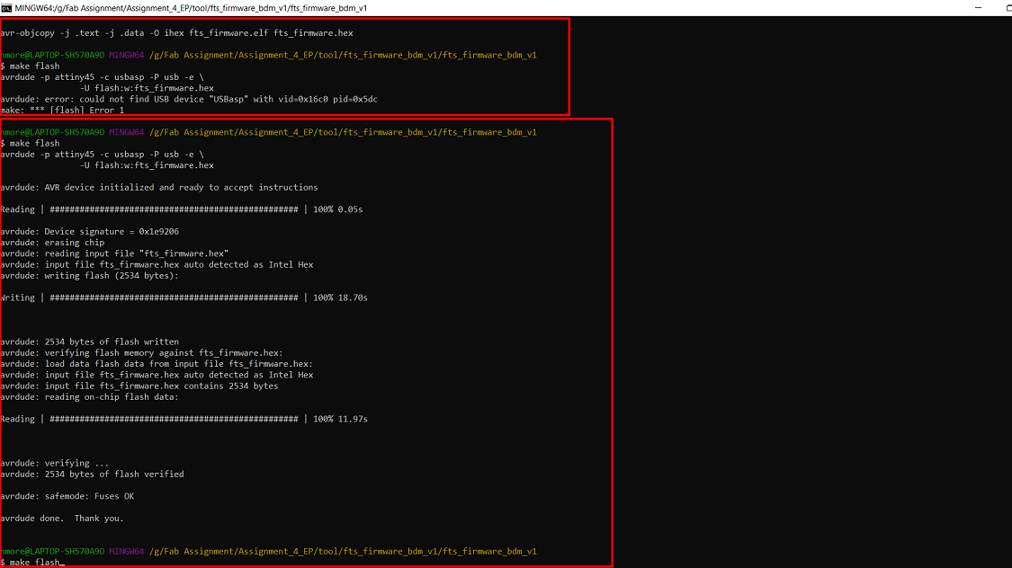
Then type "make flash">again there is error>need to change the name of the programmer in make file>again press "make flash"> ohh programm is installed succesfully
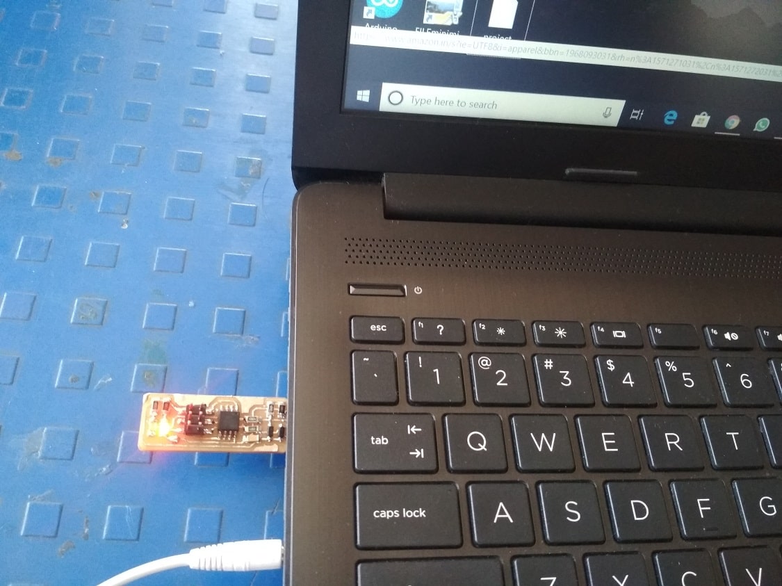
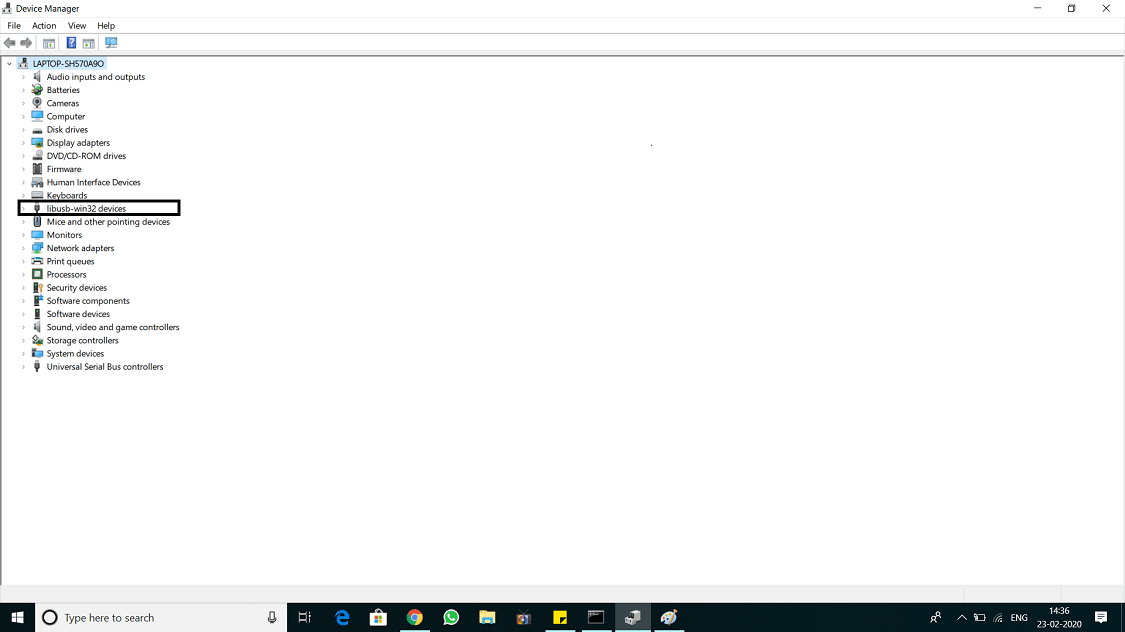
Lets check whether the programm is sucessfull or not>directly attach the ISP to laptop>the laptop shows the USB device is connected
What I learn?
1. Charaterize the design rule for PCB production process by using SRM-20 milling machine.
2. How to use "mode" for conversion of png file to rml file.
3. Machining of PCB on SRM-20 milling machine.
4. PCB soldering, component anode and cathod point indetificaton, conductivity testing etc.
5. ISP programming using Windows10 system.
Download original file here
Go to the top
Back
Assignment 6:3D Scanning and Printing
3D scanning is the process of analyzing and capturing a real object or environment and creating a virtual 3D model with the help of the collected data. 3D printing is a process of making three dimensional solid objects from a digital file.

Fab Academy Course on Digital Fabrication by Nikhilkumar More is licensed under a Creative Commons Attribution-NonCommercial 4.0 International License.
Based on a work at http://fabacademy.org/2020/labs/vigyanashram/students/nikhilkumar-more/.
Permissions beyond the scope of this license may be available at http://fabacademy.org/2020/labs/vigyanashram/students/nikhilkumar-more//contact.html