Output Devices
Week Task
Individual assignment:add an output device to a microcontroller board you've designed and program it to do something
Group assignment:measure the power consumption of an output device
Introduction
An Electronic System or circuit must be able or capable to “do” something and Sensors and Transducers are the perfect components for doing this. Devices which perform an “Input” function are commonly called Sensors because they “sense” a physical change in some characteristic that changes in response to some excitation, for example heat or force and covert that into an electrical signal. Devices which perform an “Output” function are generally called Actuators and are used to control some external device, for example movement or sound.
Different Output Devices
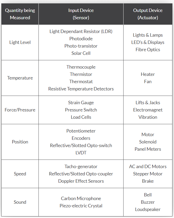
Following are the some input and output devices use in electronics circuit:
Group Assignment
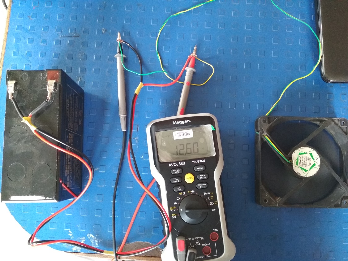
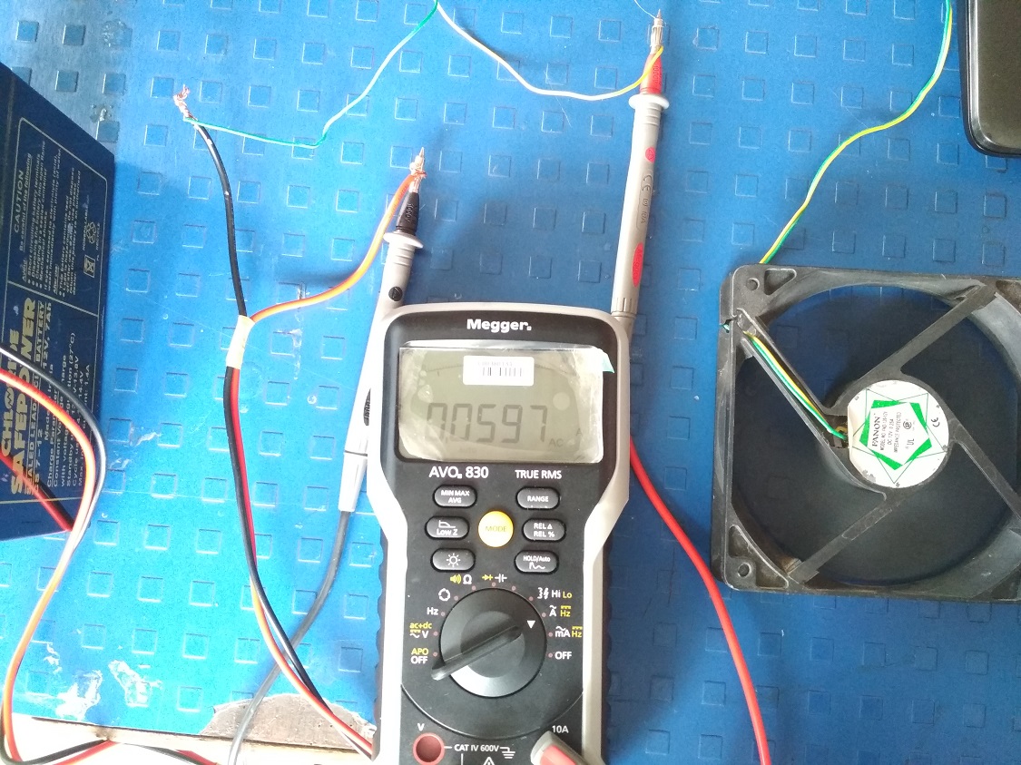
The task for the week is to measure the power consumption of an output device. During the group task, we measure the power consumption of a LCD display. For more details click here. I am also measure the current and voltage of DC fan because I have to use the DC fan for project purpose. The multimeter is used for volatage and current measurement. It is make by Megger, model AVO 830. For more technical details, click here. Fanon make computer fan is used as a output device for measurement. The manufacture specificaton fan is DC 12V, 0.25A.The measured voltage for the fan is 12.60V and current is 59.7 mA.The measured required for the fan is less than the manufacture specification.
Individual Assignment
The task for the week is to add an output device to a microcontroller board we have designed and program it to do something Due to COVID-19, Govt. of India announced the Lockdown from 22 March 2020 to 3 May 2020. The end date is also depends on the position of COVID-19. So this assignment is in between this period. Currentlly i dont have lab acess right now. So i am trying this assignment using TinkerCAD software. The board is also i have design in Eagle software. The machining i will do when i will be Lab.
1. DC Servo Motor with Arduino Board
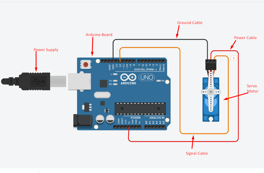
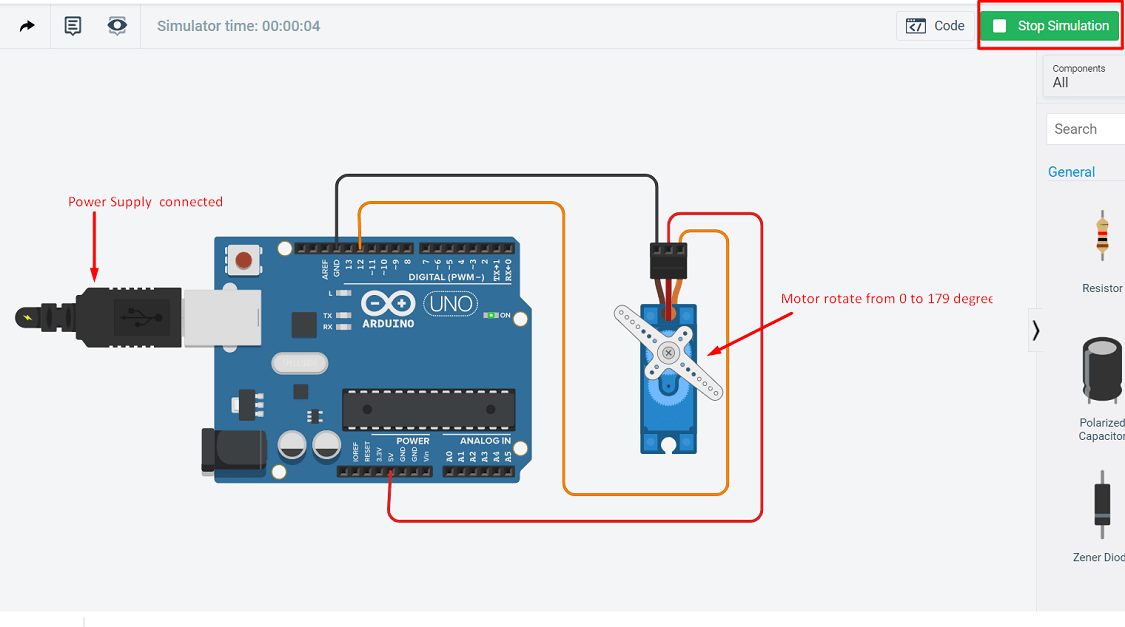
Any electrical motor can be utilized as servo motor if it is controlled by servomechanism. Likewise, if we control a DC motor by means of servomechanism, it would be referred as DC servo motor. Servo motor is a type of motors whose output shaft can be moved to a specific angular position by sending it a coded signal. The servo motor will maintain the position of the shaft as long as you keep applying the coded signal. When you change the coded signal, the angular position of the shaft will change.Here i have connected this motor to arduino board for the rotation of shaft in between 1 to 179 degree angular rotation.There are three pin for connection 1. Ground 2. Power 3. Signal. Following image shows the connection.
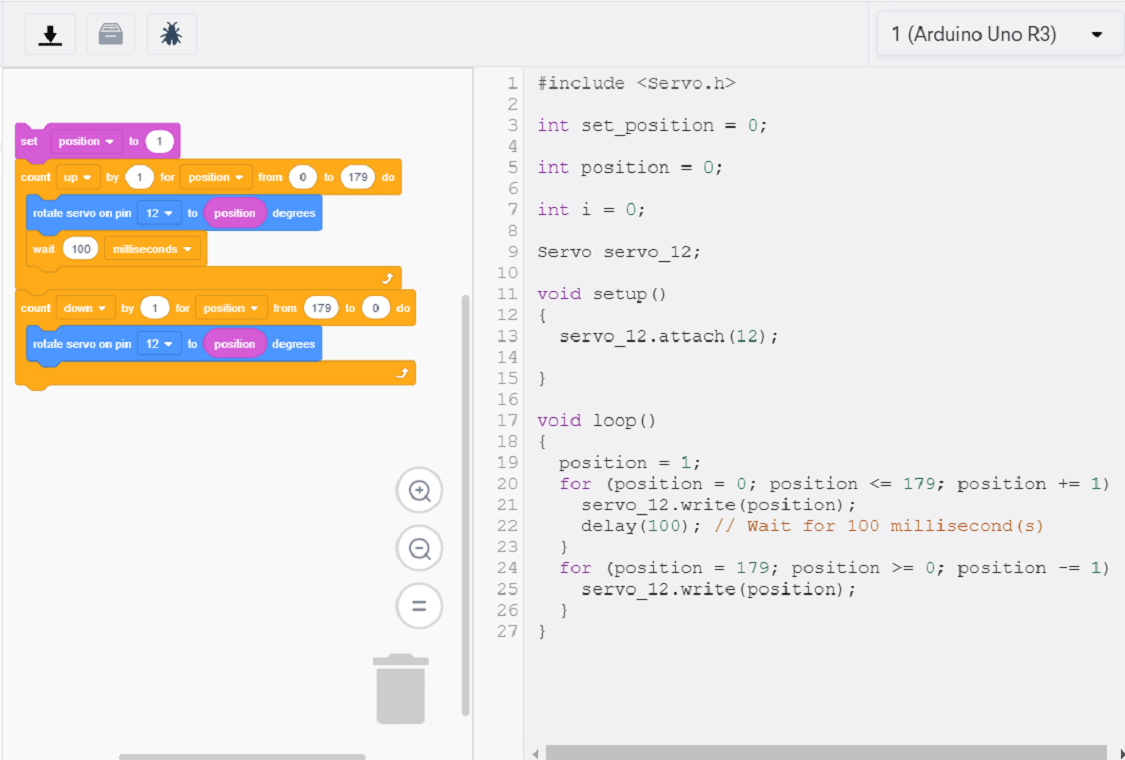
The programm for the motor rotation is develope with the help of block. The angular position of rotation in block is shown in between 1 to 179 degree, then delay of 100 millisecond and again reverse rotation from 179 to 1 degree. Here we can set any angular degree of rotation in 360 degree, just by changing the angle of rotation from and to. The signal pin of servo motor is connected to the digital pin 12 number on arduino board. We can connect the signal pin to any digital pin. That pin number we have to mention in code.Here we are using TinkerCAD simulation software. so it has may inbuilt diffrent liabrary for different devices.so there is no need to load specific liabrary for servo motor. The code is as follows
Now start the simulation, the motor is start to rotate.
Here is the video of connection and simulation.
2. 7-Segement Display with Arduino Board
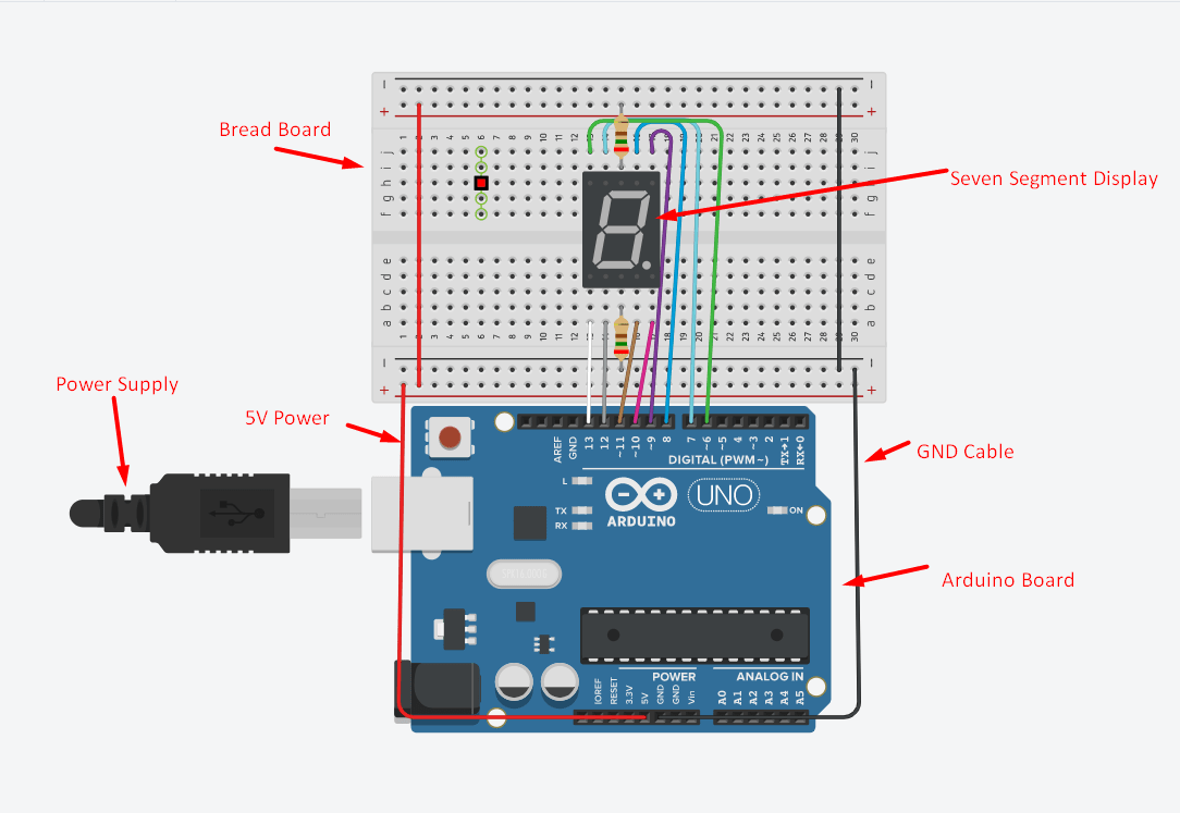
The seven segment display consists of seven LEDs arranged in a rectangular fashion as shown. Each of the seven LEDs is called a segment because when illuminated the segment forms part of a numerical digit (both Decimal and Hex) to be displayed. An additional 8th LED is sometimes used within the same package thus allowing the indication of a decimal point, (DP) when two or more 7-segment displays are connected together to display numbers greater than ten.
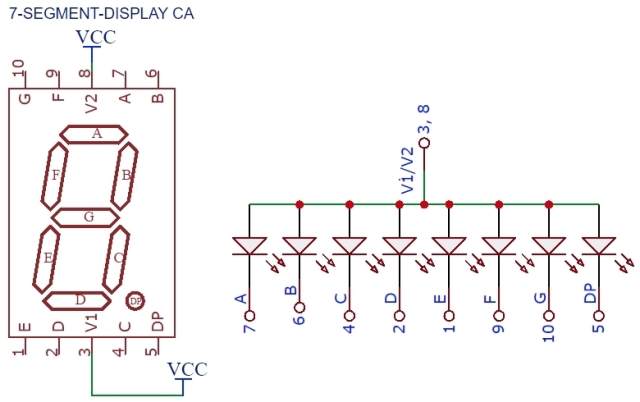
Depending upon the decimal digit to be displayed, the particular set of LEDs is forward biased. For instance, to display the numerical digit 0, we will need to light up six of the LED segments corresponding to a, b, c, d, e and f. Thus the various digits from 0 through 9 can be displayed using a 7-segment display as shown.
How to interface the seven segment display with Arduino: Here, the 7-Segment display is driven directly by Arduino. Resistors need to be connected between the display and the Arduino UNO board. Depending on which number or alphabet is to be displayed, control signals are applied.We have used common anode display, hence the common pin is connected to 5V. If common cathode display is used, the common pin needs to be connected to ground. For common anode display, drive pin LOW to turn on corresponding LED segment.For common cathode display, drive pin HIGH to turn on the corresponding LED segment.
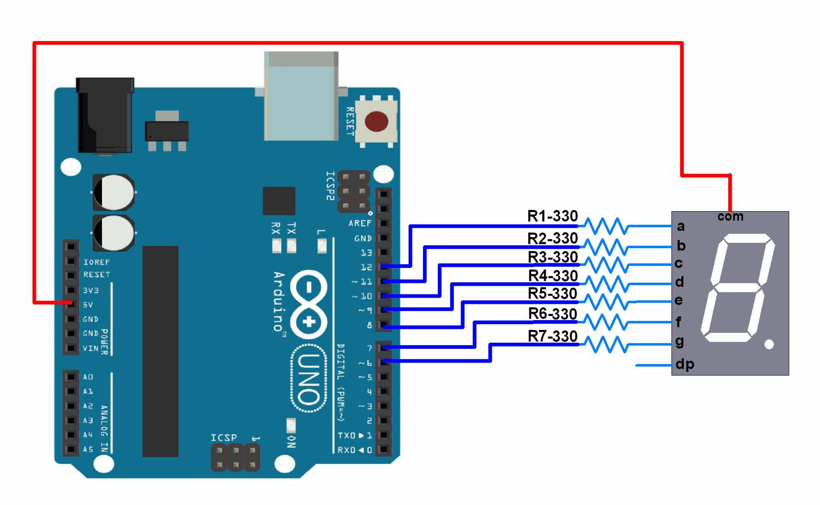
This means then that an LEDs light intensity increases in an approximately linear manner with an increasing current. So this forward current must be controlled and limited to a safe value by an external resistor to prevent damage to the LED segments. Here i have make the connection with Arduino board using TinkerCAD. A 7-segment display can be thought of as a single display, it is still seven individual LEDs within a single package and as such these LEDs need protection from over current. The voltage drop for the LED is around 2 to 2.2 volt. The supply voltage through the arduino is 5 volt. The LED segement can draw around 15mA current. The value of current limiting resistor required is R=V/I=5V-2V/15mA=200ohm. Two LED connected parallery of 0.20 Kohm. LEDs produce light only when it is forward biased with the amount of light emitted being proportional to the forward current.
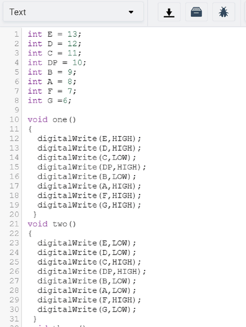
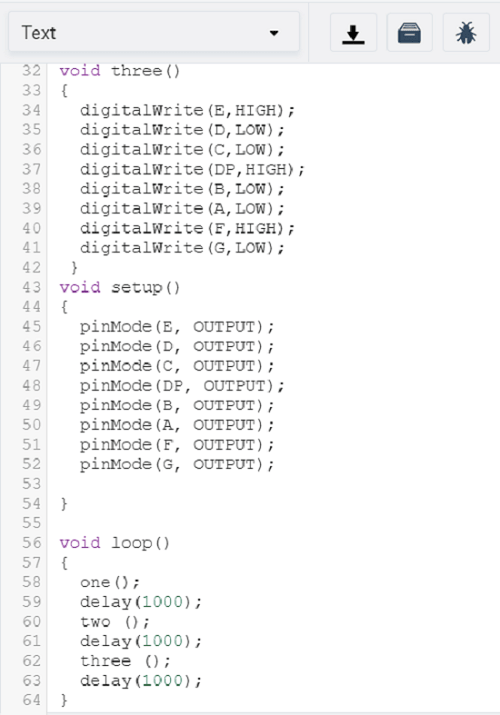
The programm for to display 1 to 3 digit is write here.
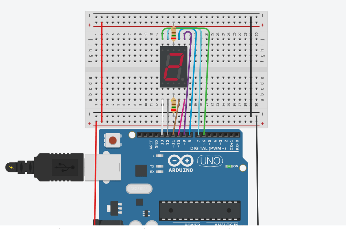
Now start the simulation, the display shows 1 to 3 digit.
3. DC Motor and LED as a Output Device with Arduino Board
Basically in my final project, i have to use two dc motor and two LED as a output device for working smart kitchen chimney. Smoke sensor is taken as a input device in that case. So here i am trying to develope this board using TinkerCAD software. When i will be in lab, then i will use microcontroller ATtiny 44 IC for the same input and output device. Lets see the connection made here
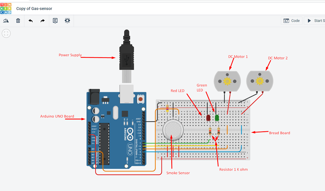
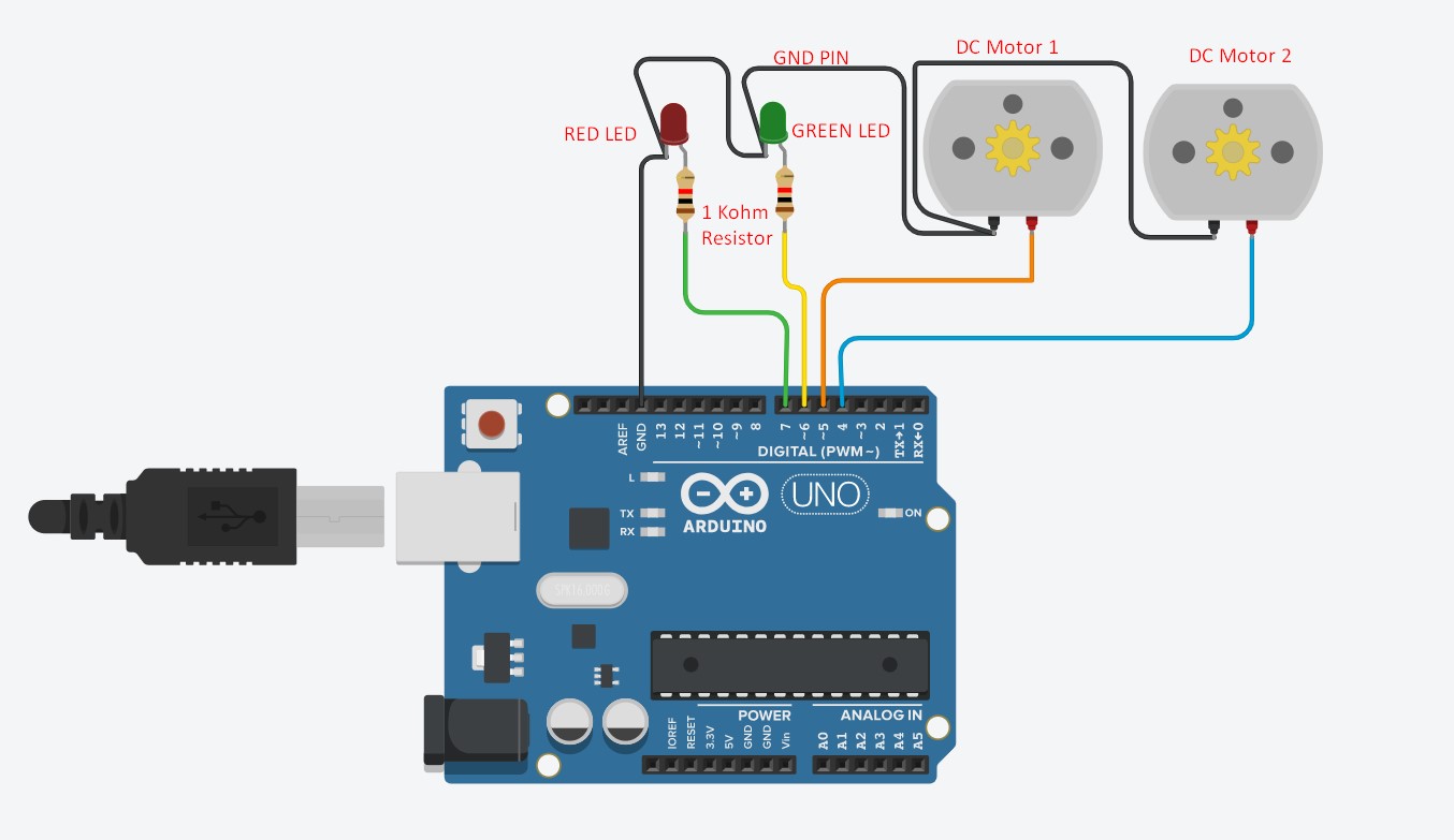
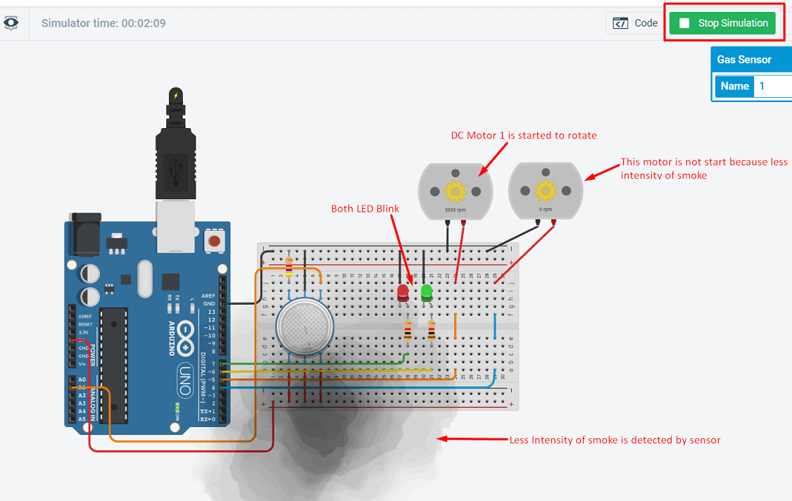
How to interface the DC motor and LED with Arduino Uno: Two DC motor and two LED (Red and Green) is connected to arduino board. Resistors of 1 Kohm for each LED is connected on anode side in between LED and Arduino. Red LED is connected to the digital pin 7 and green LED to the pin 6 of arduino board. The two DC motor is also connected to the arduino board. There is also two pin. Ground pin is commonlly connected GND pin arduino and DC motor1 signal pin is connected to the pin number 5 and DC motor 2 signal pin is connected to the pin number 4 of arduino. The wiring diagram shows the connection.
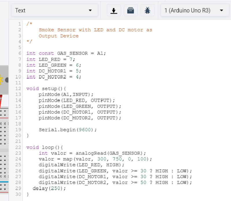
Here i am trying to develope the program directly using text.
Now start the simulation, there is a two LED is used, Red LED shows the power supply is "ON" and sensor is detecting the smoke
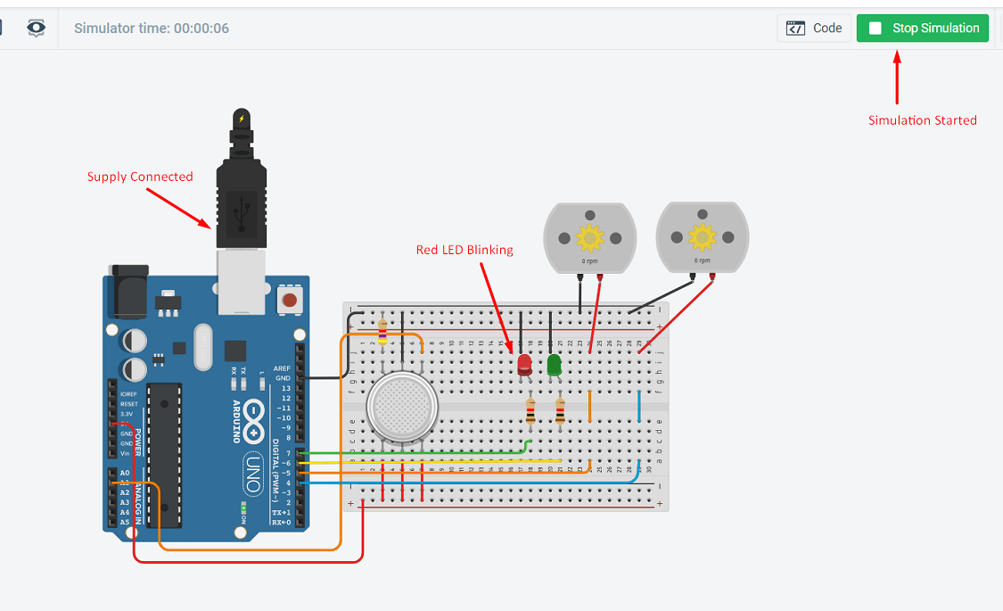
As the smoke is detected by the sensor, the First DC motor will get start and green LED will blink In this case the smoke intensity is less so only one motor is getting start.
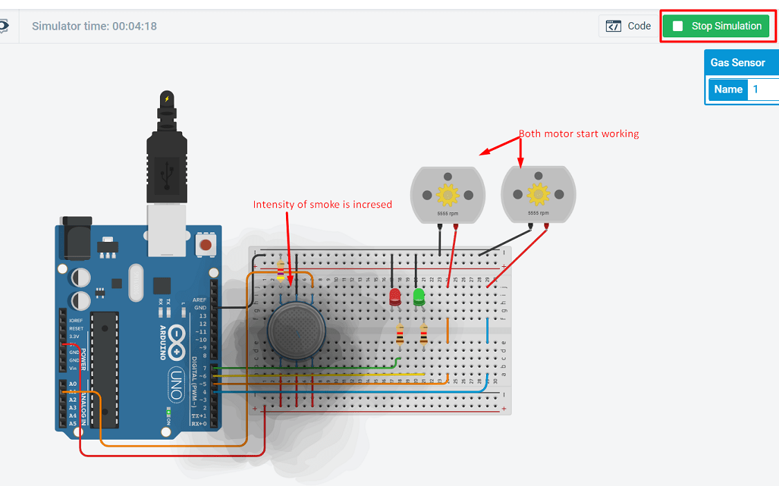
As the smoke intensity is increased, the second motor is getting start. Both motor are now running
Here is the video of connection and simulation.
Board Design using Input and Output Devices for final project
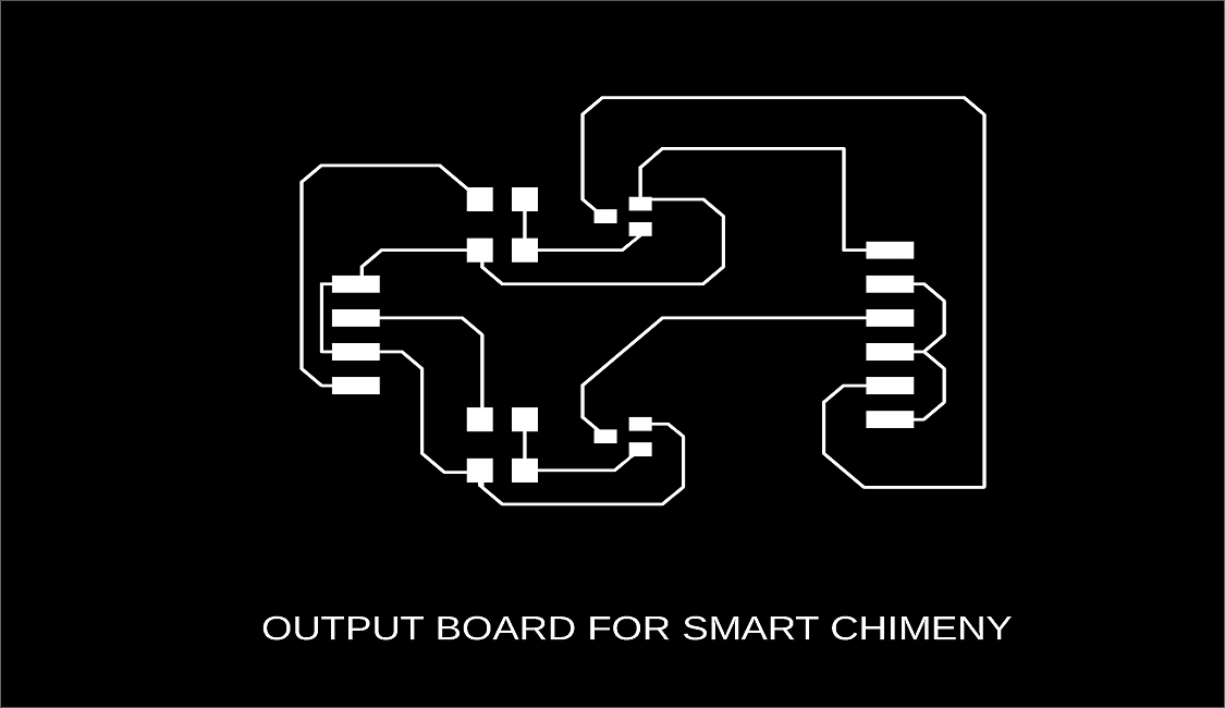
As shown in above simulation, this all devices I am going to use in my final project. So here i have develope the board in Eagle software. There is two DC motor are using to run a fan in kitchen chimney. The motor is around 5W rating, so i will use PNP MSFET to controll the motor, because if I will directly connect thic motor on the board, due to high current the microcontroller may get damage. PNP MOSFET is connected with the microcontroller i.e. ATtiny-44.Now I have come to the lab on 23 June and start working. Firstly I discuss with my instructor and make the necessary changes in this board. The final I have put here. The schematic design is as follows:
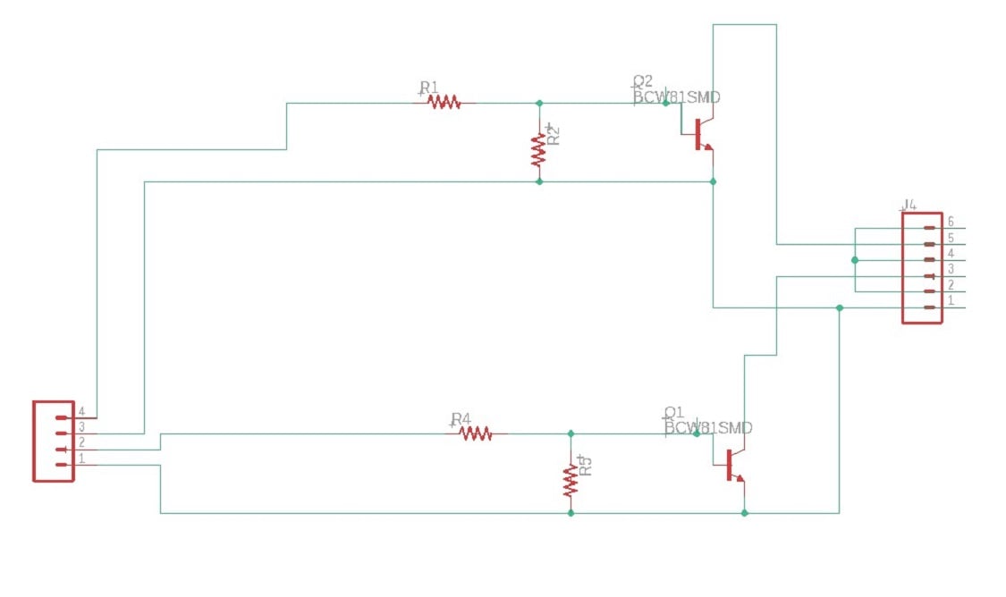
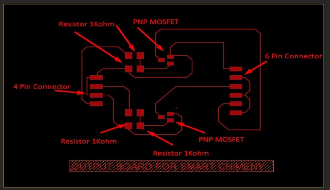
The board design is as follows:
Why PNP MOSFET?
The PNP transistor has a Positive-Negative-Positive type of configuration, with the arrow which also defines the Emitter terminal this time pointing inwards in the transistor symbol. Also, all the polarities for a PNP transistor are reversed which means that it “sinks” current into its Base as opposed to the NPN transistor which “sources” current through its Base. The main difference between the two types of transistors is that holes are the more important carriers for PNP transistors, whereas electrons are the important carriers for NPN transistors So here I am selected PNP MOSFET because the load is connected to ground (0v) and the PNP transistor switches the power to it. To turn the PNP transistor operating as a switch “ON”, the Base terminal is connected to ground or zero volts (LOW)
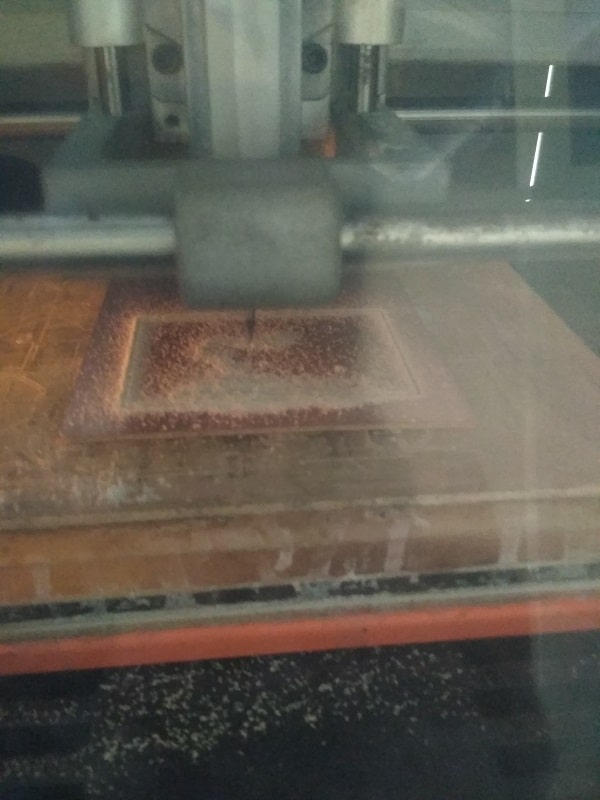
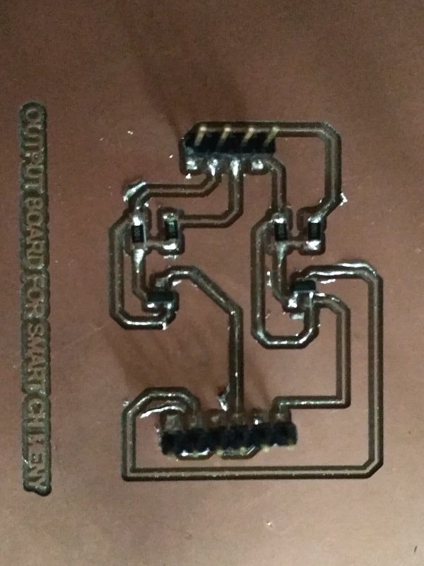
PCB Milling and Soldering
Firslty the image is exported as a png file from the Eagle software. Then this file is converted into the rml file. Two file is created one for trace and other for cut. Then file is loaded on SRM-20 PCB milling machine.(For more details refer my Assignment 5 and 7). After milling the component is soldered on the PCB. and finally conductivity is tested. Now the Output board is ready.