Week Task
Design and produce something with a digital fabrication process (incorporating computer-aided design and manufacturing) not covered in another assignment, documenting the requirements that your assignment meets, and including everything necessary to reproduce it.
Introduction
The task for the week is to design and produce something with a digital fabrication process. Our college have developed the Sant Gajanan Tool Room. It is a advanced tool room having number of CNC machine for training and production purpose. So I have decided to completed this assignment in the tool room using Vertical Milling Machine. I have developed one of the design in FreeCAD software and try to machining this object on the machine. There is no specific obejective behind design the object. Just I have include different profile in the design to characterise the machine. In the design there is bore, pocket, round surface, plane surface etc. type profile. So lets discuss the procedure of machining using CNC Vertical Milling Machine.
Design of object
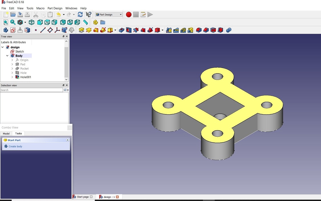
The design is created usign FreeCAD-2D, 3D design software. Here is the isometric view of the object.
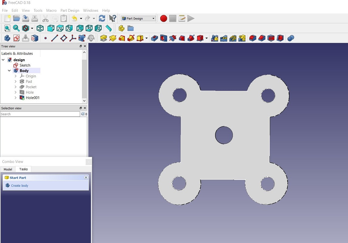
Following is the backside view of the object. Where it shows the bore on the object.
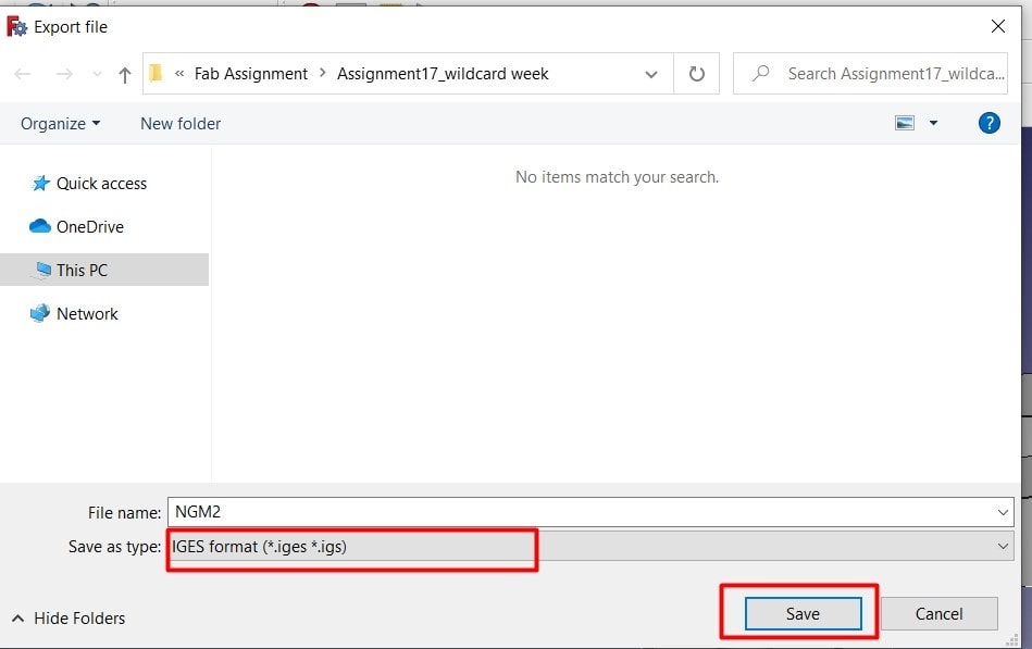
After complete design of the object, the design is exported from the design software and saved in IGES Formatt. Click on file>export>save as type: .iges
Toolpath Creation
After the design, the next part is toolpath creation using CAM software. For the purpose NX-3 softwar is used to create the G-Code and M-code of the machining
process. The design is imported in the software. Three operation is created for complete machining of the object.
1. Outer Surface Milling 2. Cavity milling 3. Drilling operation.
Firstly create the operation. The following opetion will open. By selecting particular geomtry the NC_programm we have to create, this is our operation.
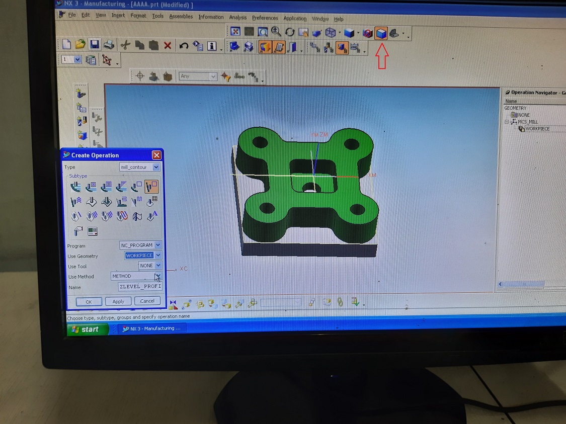
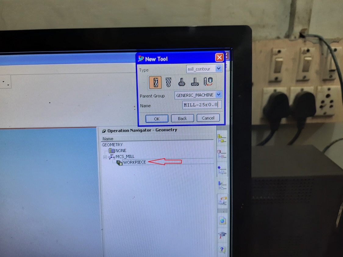
By clicking on the workpiece, the different opeartion will be created. so firstly we will create the code for Outer Surface Milling. Firstly select the tool for the opeartion, here it is 25 mm we will used. put the value there and click OK.
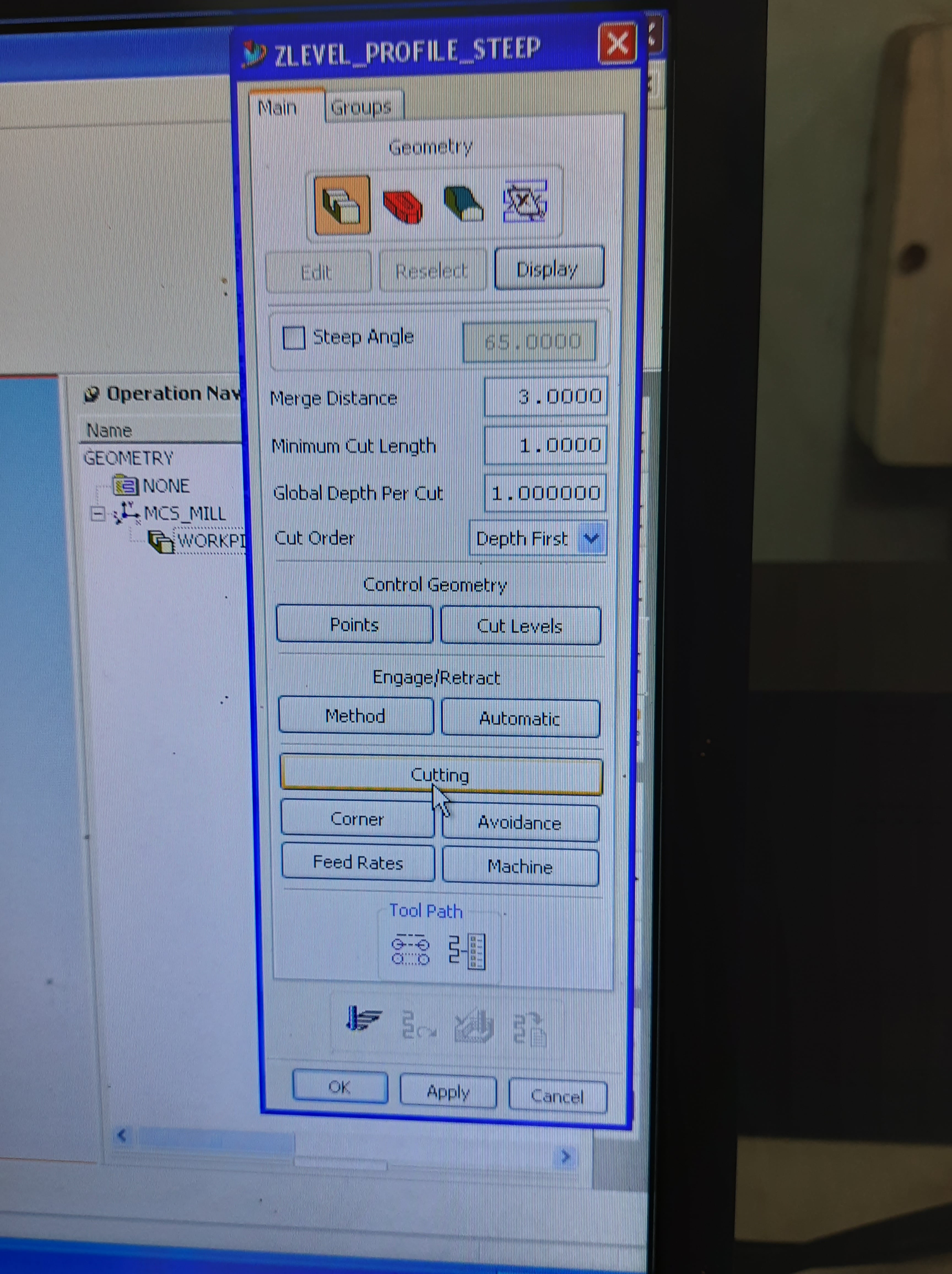
The next window will open for the particular opration. Then select the merge distance, minimum cut length, global depthe per cut, cut order. Then click on "Cutting" for speed and feed selection.
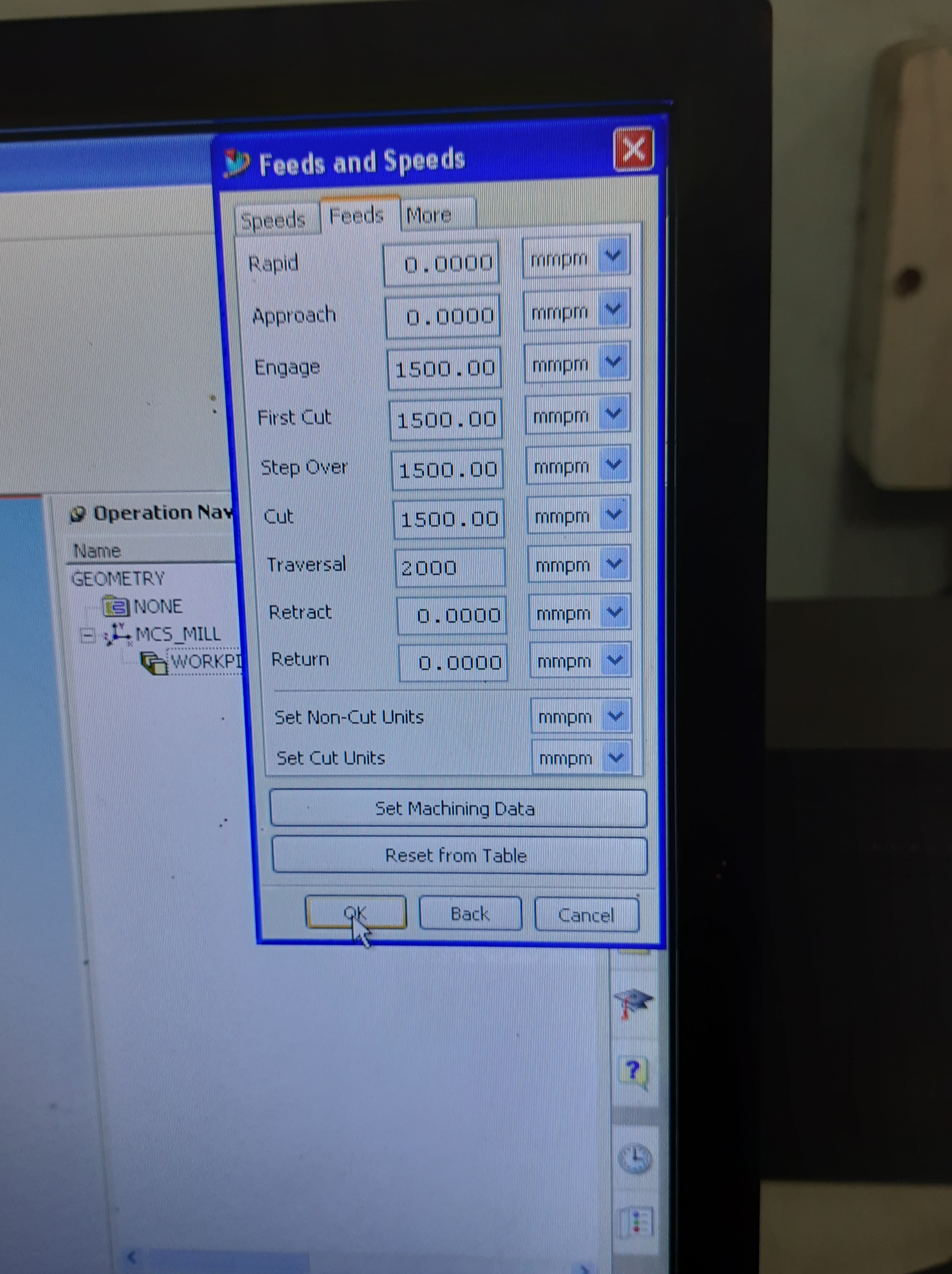
Put the different value for different feed and click OK.
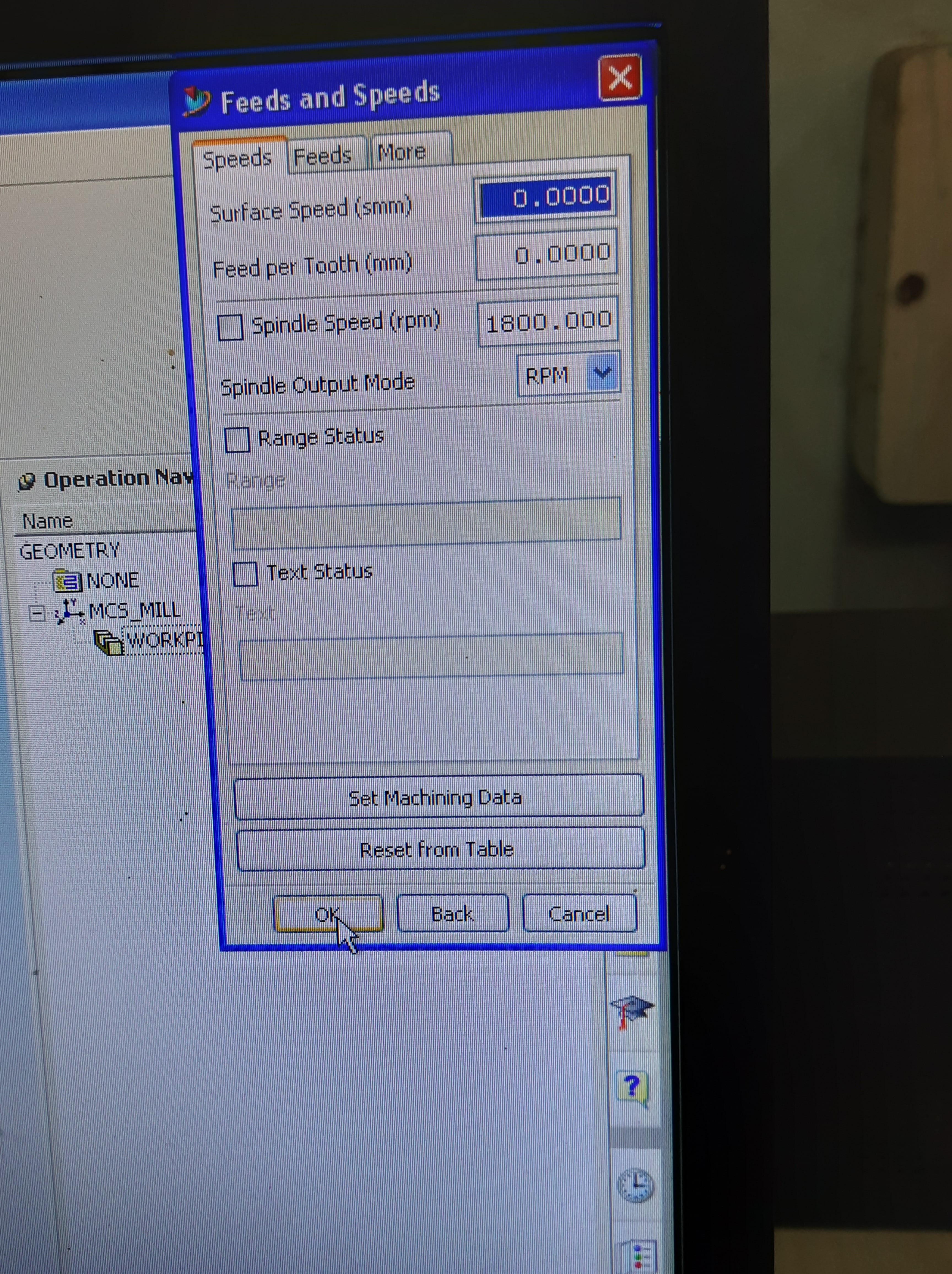
The select the spindle speeds in rpm and click OK.
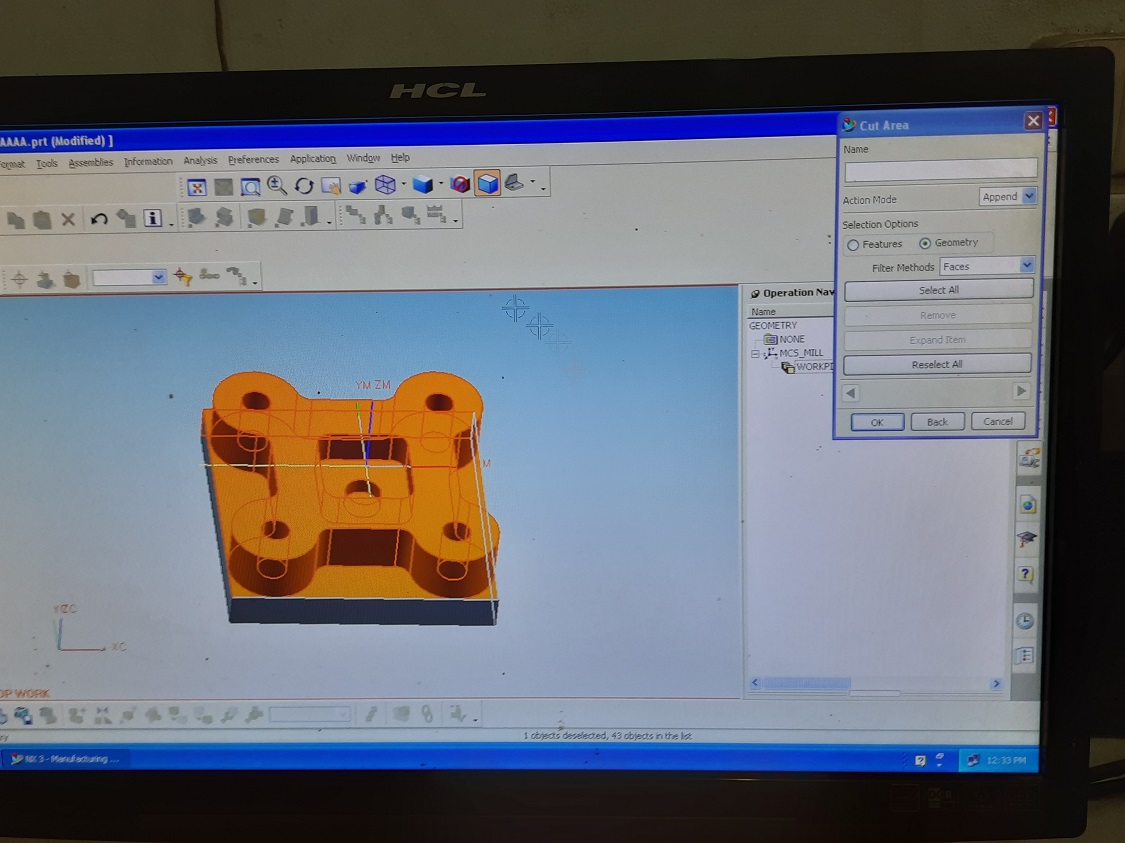
Then select cut area and click ok. The operation will be created now.
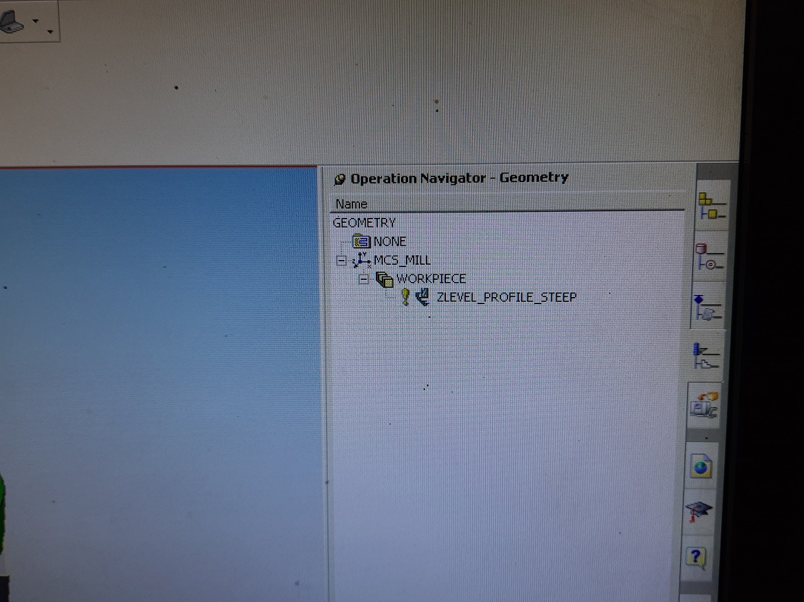
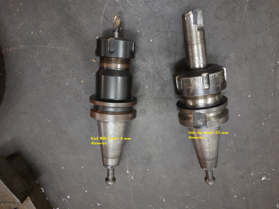
Now the code is created for zlevel profile steep i.e. for outer surface milling. It is a rough milling operation. After the cavity milling, we will again create the code for finishing cut. For rough machining, here we will used 25 mm side lip cutter and for finish machining 8 mm end mill cutter is used.
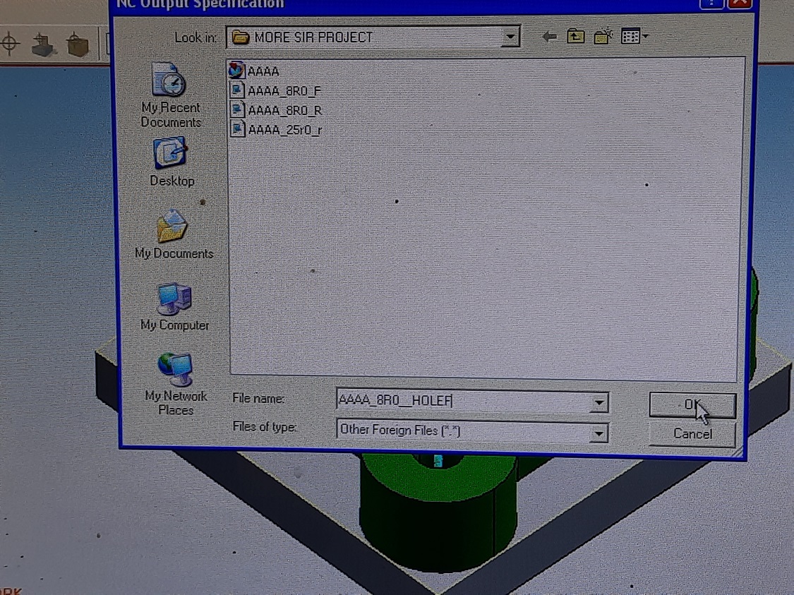
Simillarly we have create code for cavity milling and next code for boring. After creation of toolpath, the file is exported from this software and saved in USB drive for to connect with machine.
Machining using Vertical Machining Center
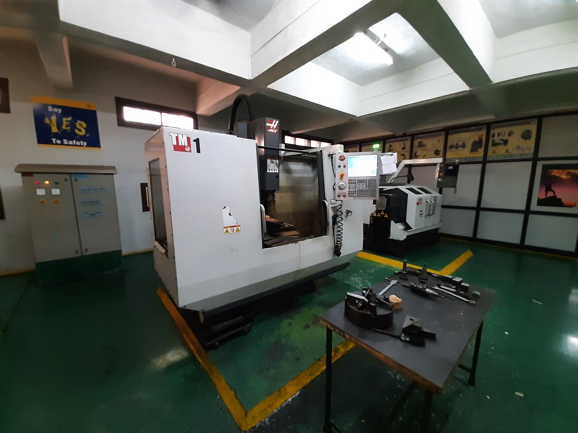
After succesfulll creation of the toolpath for the design, now the next part is machining.The machine used for the purpose is HAAS make CNC Controll Vertical Milling Machine of TM series. The TM Series Toolroom Mills are affordable, easy to use, and offer the precision control of the Haas CNC system. They use standard 40-taper tooling, and are very easy to learn and operate – even without knowing G-code. Click here for Technical specification of the machine.
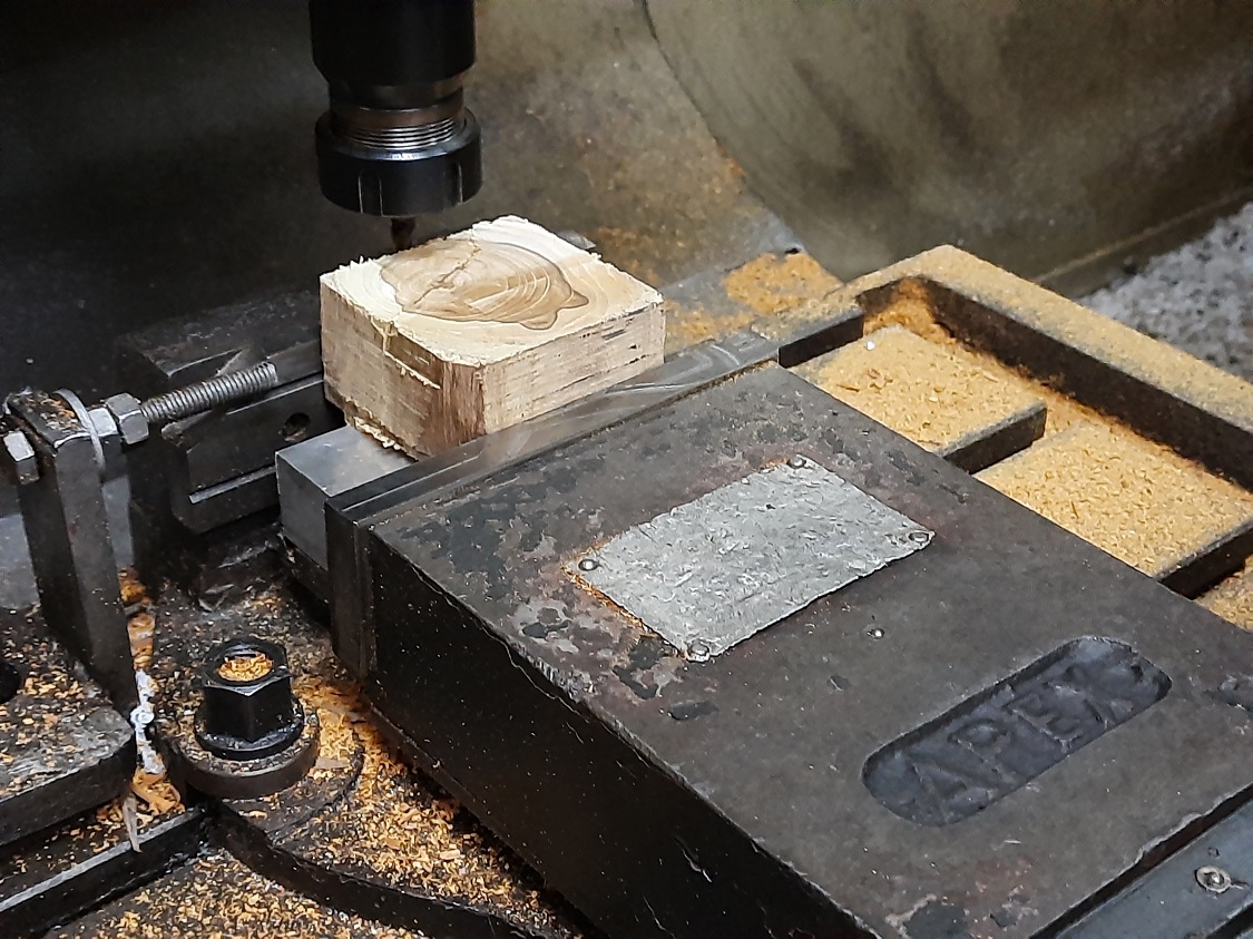
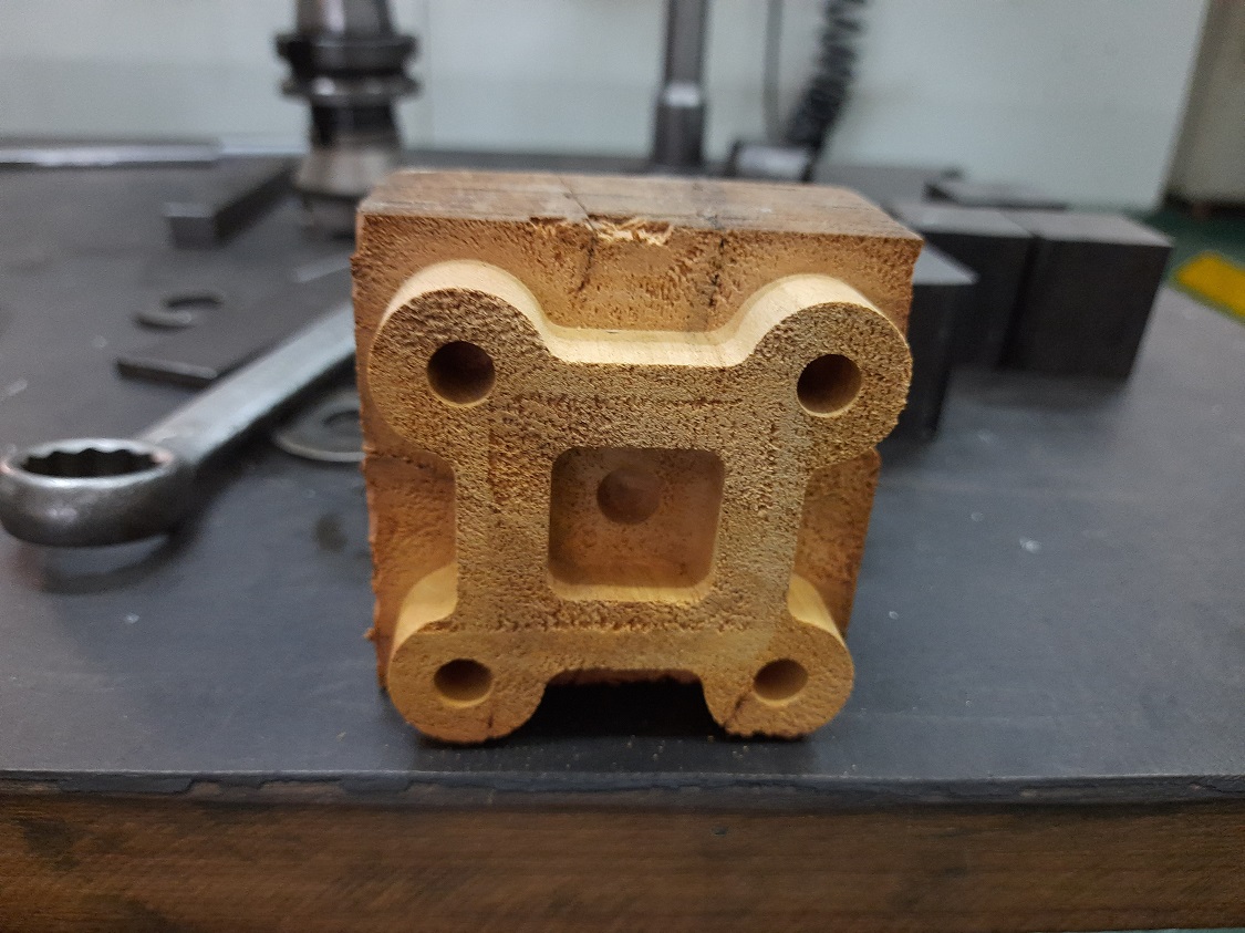
Currently wood material is available. The wood block of 80 mm (L)x 80 mm (W)x 50 mm (H) is fitted on the work table. Now the main task is to set the x & y axis of the tool
For the purpose, we have done the mannual setting through controll pannel.
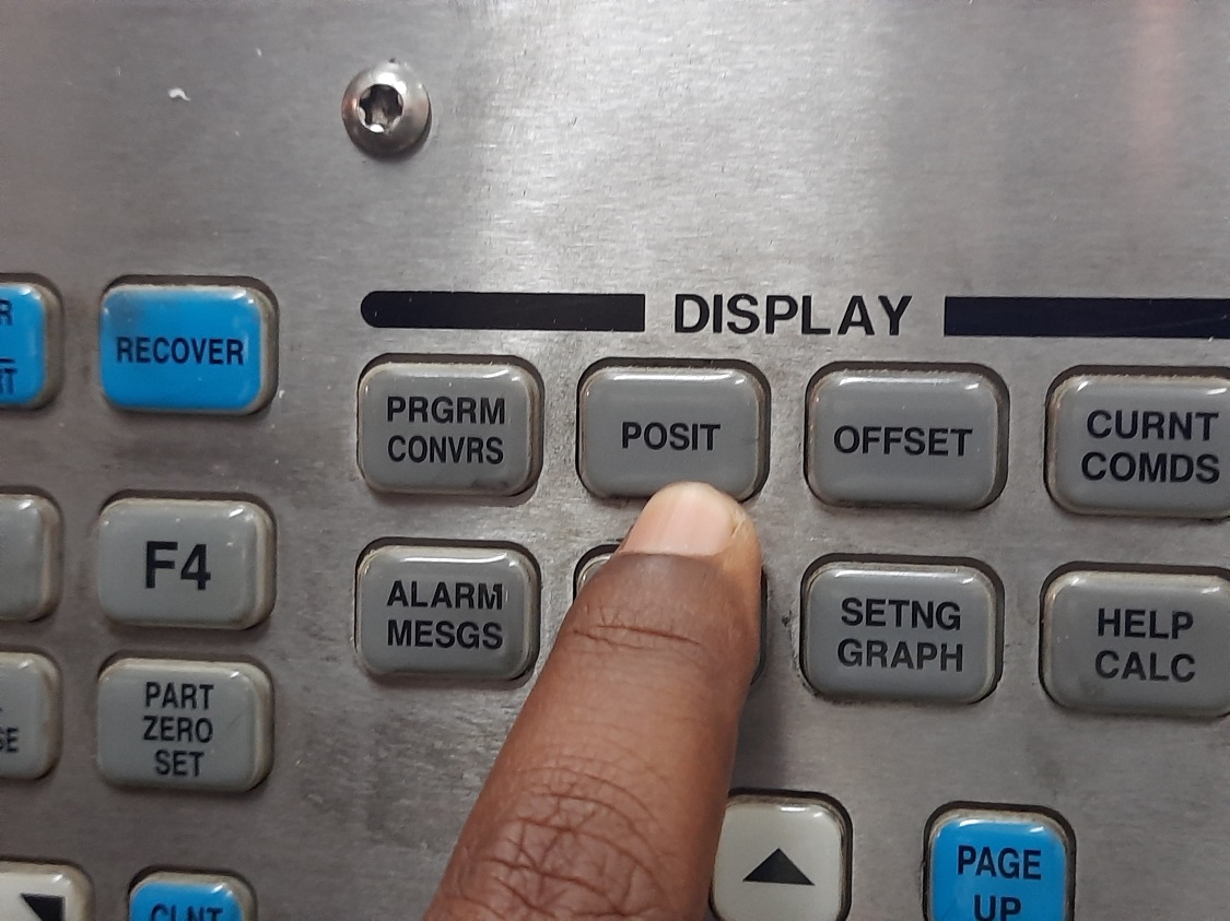
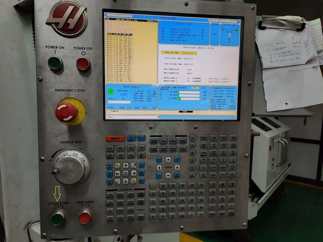
Fistrly press [POSIT] on the controll pannel
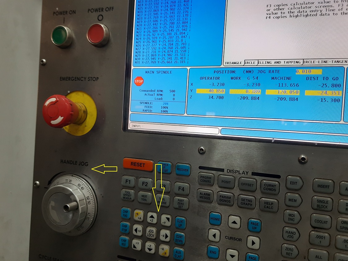
Then move the tool at the required position. For the direction of movement of the tool press the button, in which direction the movement is required.By using handle jog, the tool is move in the set direction.
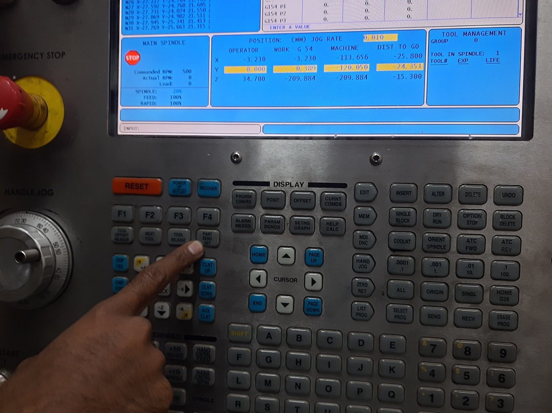
The orgin is set at the conter of the object not at the corner of the object. The press [PART ZERO SET] to confirm the orgin. The position of the origin is displayed on the screen.
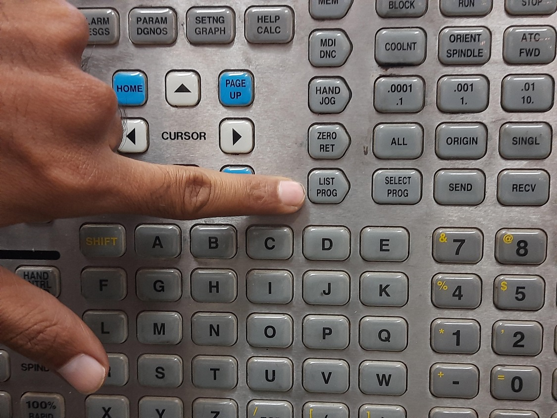
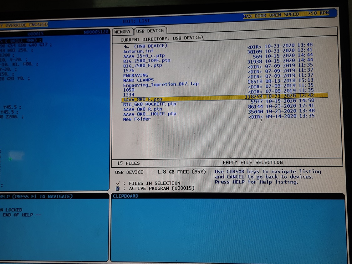
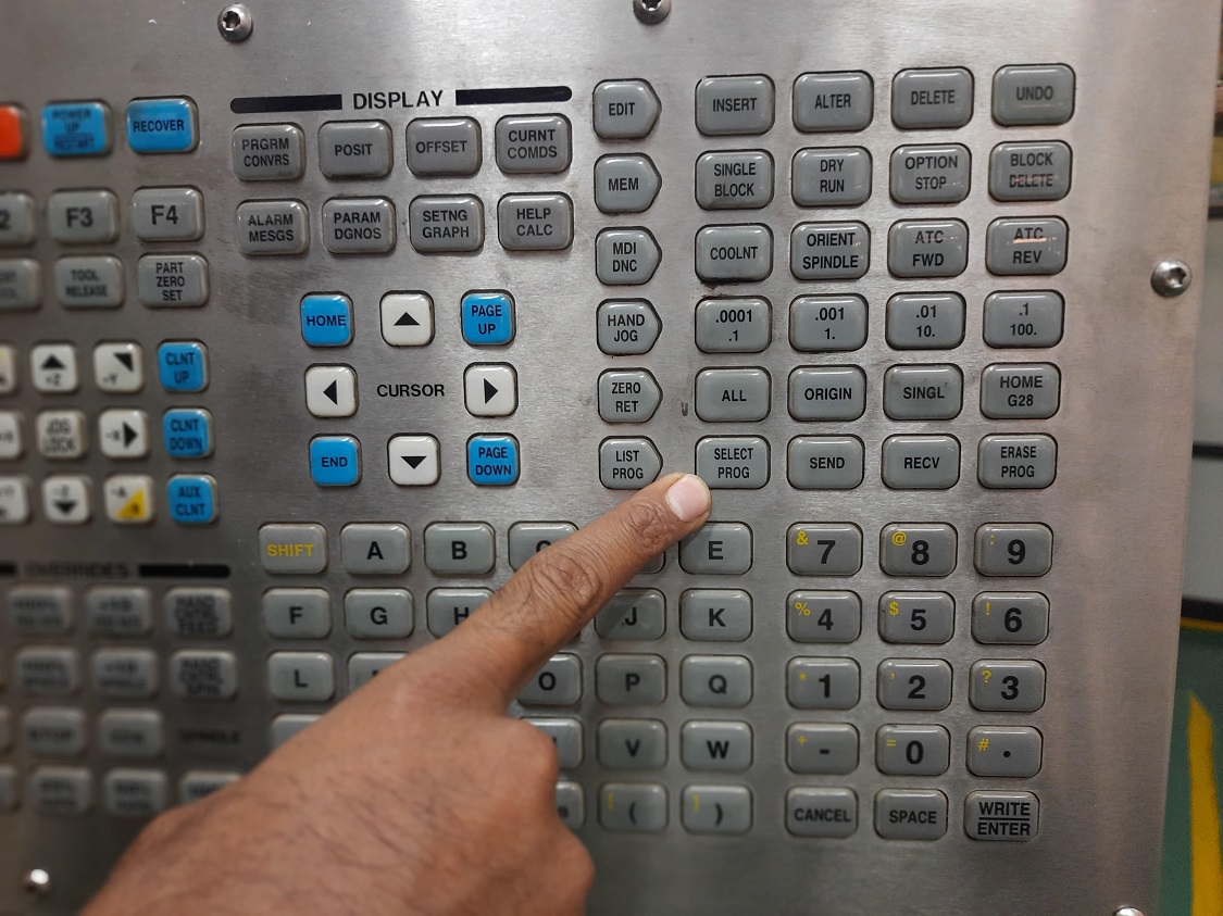
Connect the USB to the machine, press [LIST PROG] to open the list of the programm.Move the cursor on the required programm. Then select the particular programm that we have to run first by press [SELECT PROG].
Graphic Mode: A safe way to troubleshoot a program is to press [GRAPHICS] to run it in graphics mode. No movement occurs on the machine, instead the movement is illustrated on the screen.
The tool tool used for the purpose is side lip cutter of 25 mm diameter. For pocket milling,surface finishing and drilling the tool used is end mill cutter of 8mm diameter
Then press [CYCLE START] to start the machining. Here the first programm is outer surface rough milling
The machining is start now.
Simillarly the second programm is load for the pocket milling. Tool is changed, end mill cutter is used now.
Then the next programm is load for finish cut using end mill cutter
Final operation is boring. The programming is load for boring operation.
The finished part is here. The machining is completed in very short time. Because it is a mass production machines
What you have learned?
I am learn about
1. Part design using FreeCAD Software
2. CAM programming for Vertical Milling machine using CAM Software
3. Loading the part and programm for machining
4. Characteristics of the machine
Go to the top
Download original file hereBack
Assignment 18:Mechanical Design, Machine Design
The task for the week is to develope the mchines that include mechanism, actuation and automation

Fab Academy Course on Digital Fabrication by Nikhilkumar More is licensed under a Creative Commons Attribution-NonCommercial 4.0 International License.
Based on a work at http://fabacademy.org/2020/labs/vigyanashram/students/nikhilkumar-more/.
Permissions beyond the scope of this license may be available at http://fabacademy.org/2020/labs/vigyanashram/students/nikhilkumar-more//contact.html