Electronics Design
Week Task
group project:use the test equipment in your lab to observe the operation of a microcontroller circuit board
individual project: redraw an echo hello-world board, add (at least) a button and LED (with current-limiting resistor), check the design rules, make it, and test it
extra credit: simulate its operation
Introduction
An electronic circuit consists of various electronic components like resistors, capacitor, diodes and transistors connected by a wire,
through which current flows in the circuit. Nowadays, instead of connecting the components through a wire, components are soldered to the interconnections which are created on the printed
circuit board (PCB) to form a finished circuit. A schematic circuit diagram is the representation of components and interconnections in a circuit using standardised symbols without using the
actual image of the component. Circuit diagrams are used for design, construction and maintenance of the electrical and electronic equipment.
Individual Assignment
The task for the week is to redraw an echo hello-world board, provided by Fab Academy and add (at least) a button and LED (with current-limiting resistor), check the design rules, make it, and test it. So to redraw the echo hello-world, I used Eagle software and also i am tried Easy Eda software.
Redrawing of Echo Hello-World Board
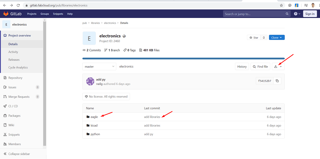
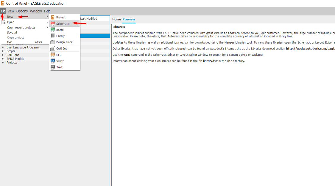
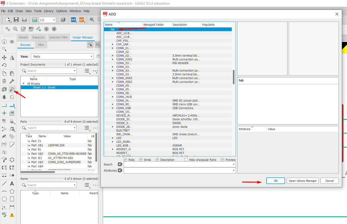
Firstly i downloaded the Eagle software and installed it. Then i have download the Fab libraries from the given link. Extracted the folder in a my documents folder.
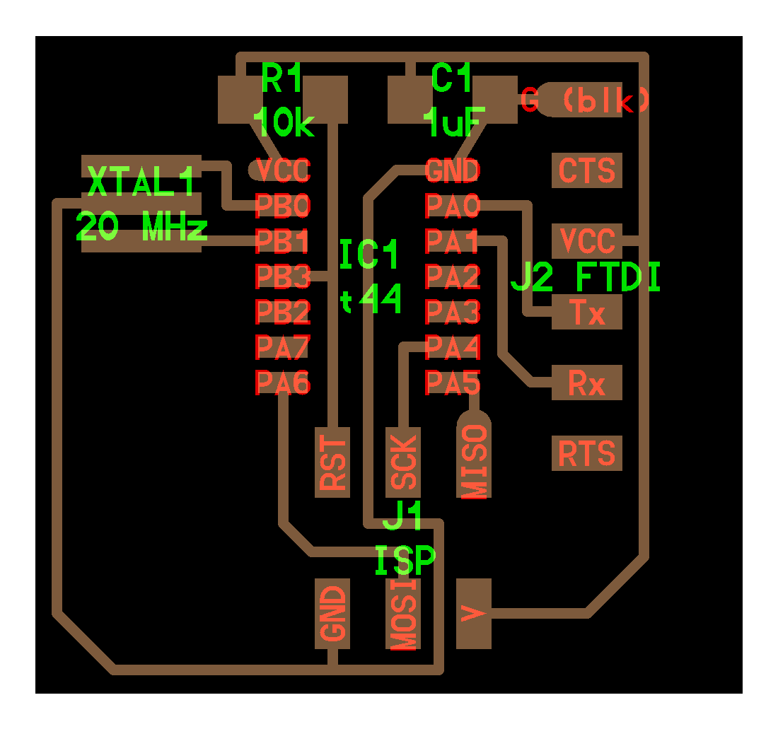
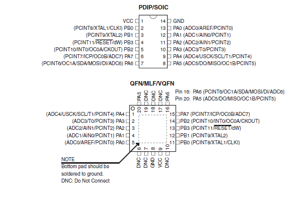
Now i refer the list of microcontroller, given by Fab Academy, searched its details, The ATtiny44 microcontroller has 14 pins, which is suitable for my project work. So i choose ATtiny44 microcontroller for my Echo hello-world board. I refered the this png image.
Now i opened the Eagle software, installed the Fab libraries in the software.
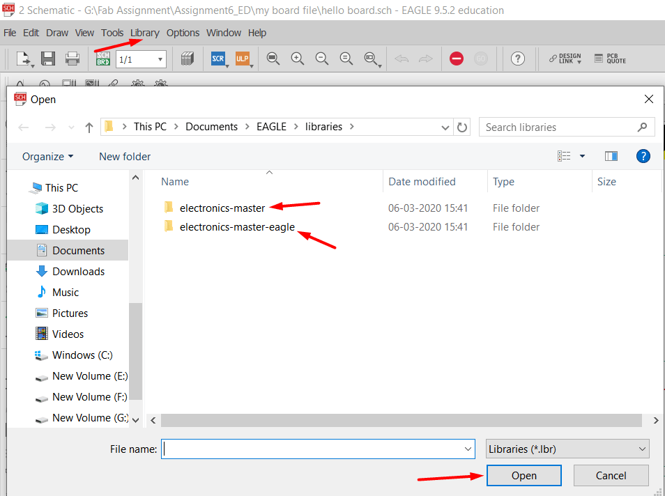
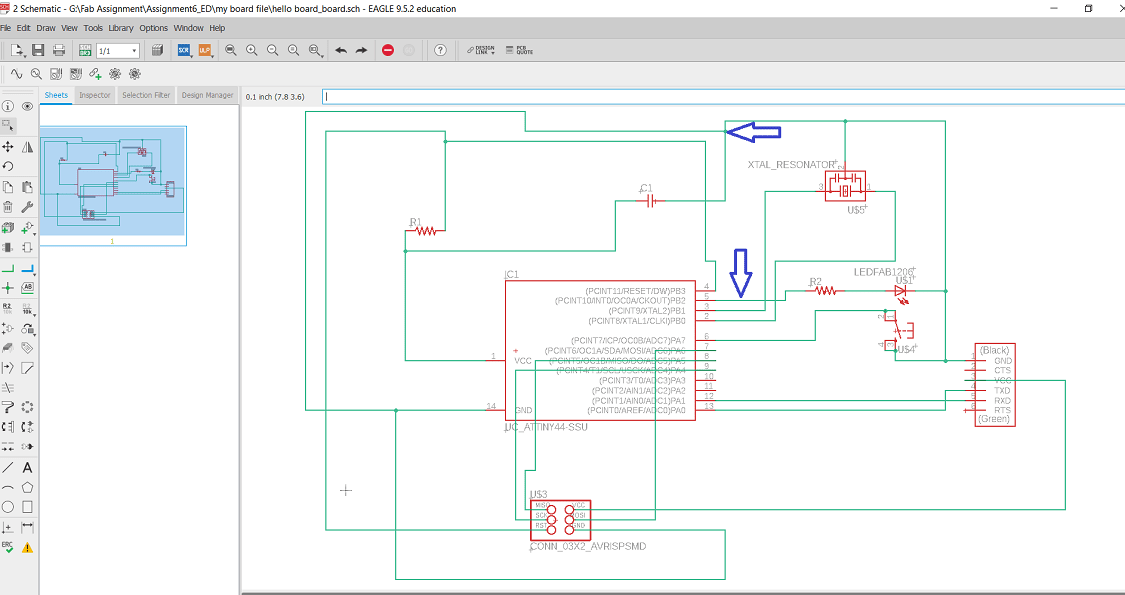
For schematic diagram, i have taken the components, required for circuit from the Fab Library.
Now connected all the components as per the given diagram. I have extra added one button and one LED with resistor, it is connected to microcontroller. Before the connection i have refer the pin diagram of IC, which is the I/O port and other.
List of the components used in my Echo Hello-World board is 1. A capacitor-01 Nos. 2. A resistor-03 Nos. 3. A resonator-01 Nos. 4. A LED- 01 Nos. 5. Pin Header- 01 Nos. 6. A switch -01 Nos. 7. ATtiny44 microcontroller
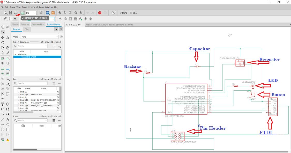
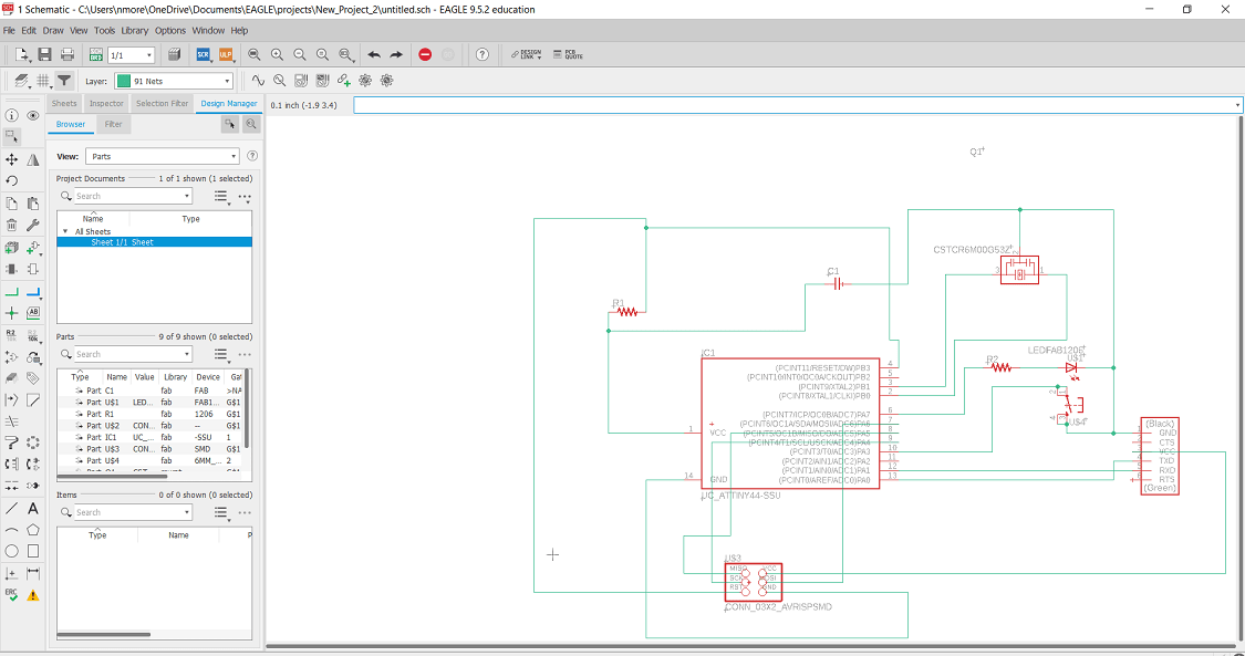
For schematic diagram, i have taken the components, required for circuit from the Fab Library. Connected all the components as per the given diagram.
After this, now its time to create the board and arrange all the components properly. So i click at "Genearte/switch to board". Now the board is created like this.
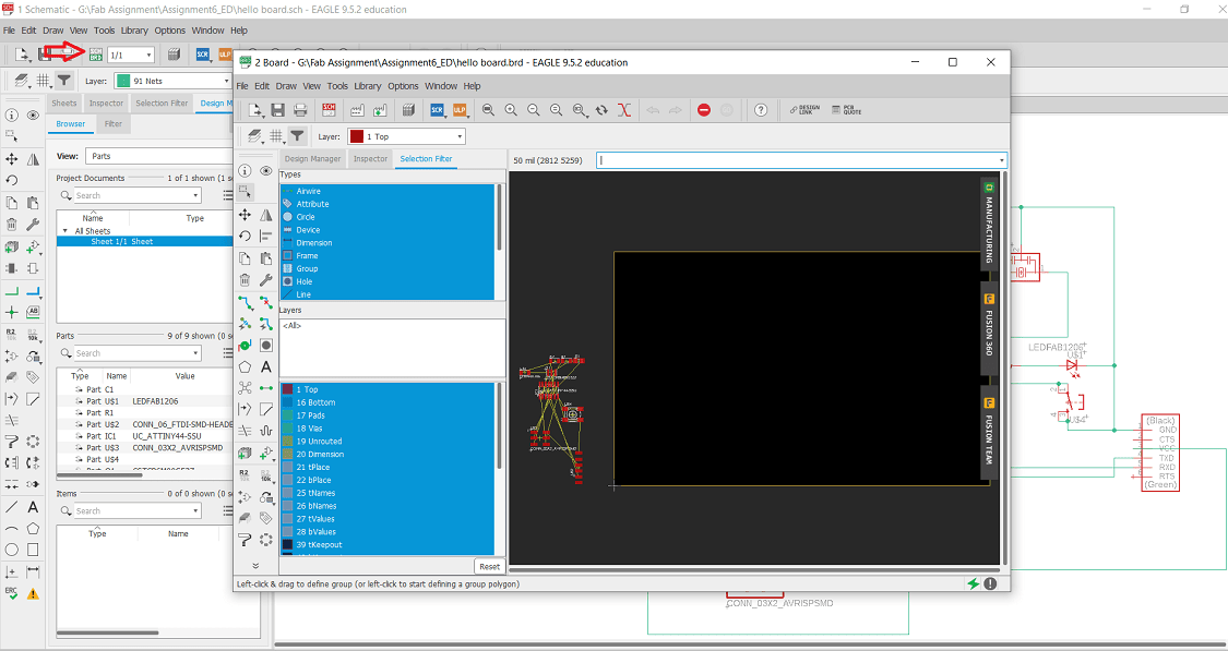
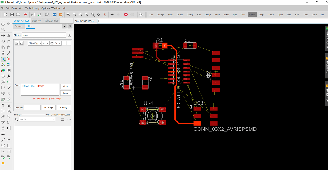
Now moved the circuit on board and arranging the components properly so that the track can not be overlap each other.
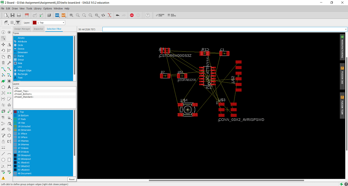
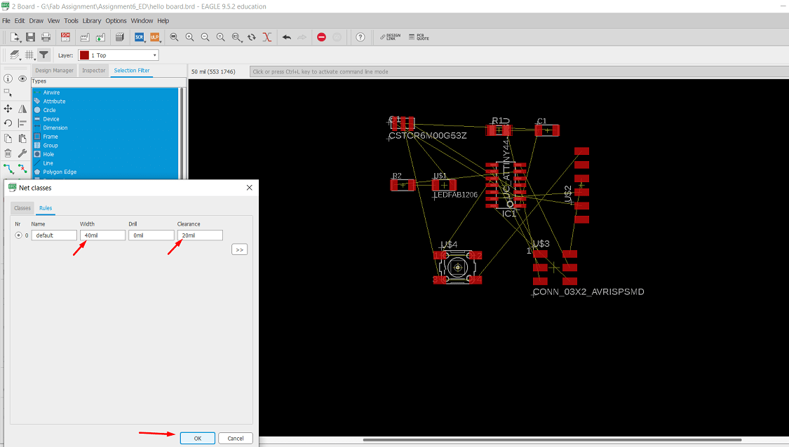
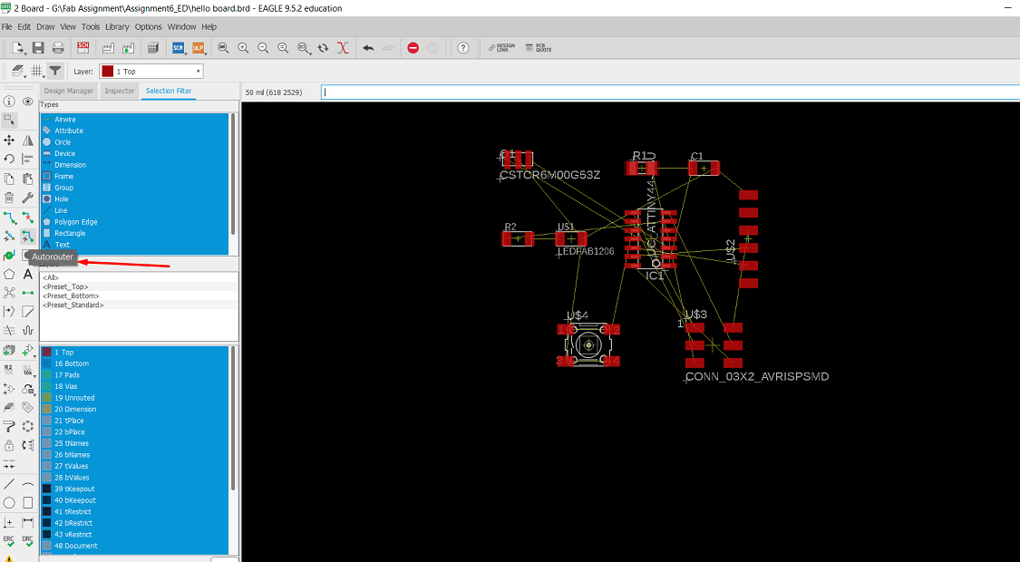
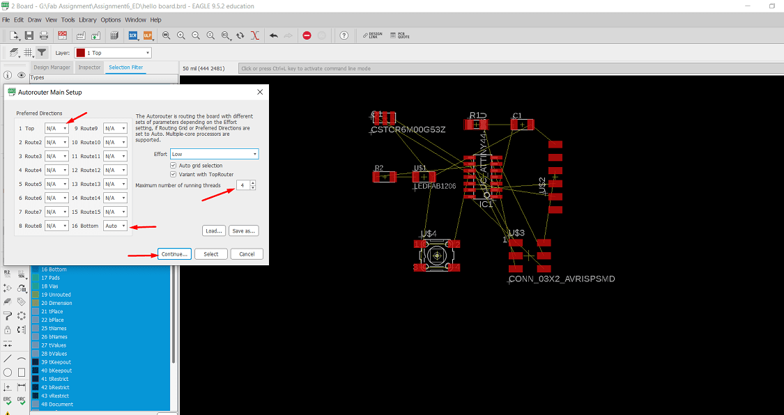
Now I am trying to create the path by using "autorouter" option. For that i am set width of path and width of clearance. Firstly click on Edit>Net classes>rules>width and clearance.
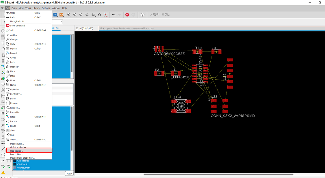
Then click on Autorouter option.
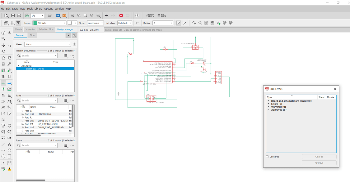
But the Autorouter is not functioning, So now click on tool>ERC>the ERC errors will get open> resolve the errors>in my case power pin is not connected to VCC and GND is also not connected. so i reconect this all one
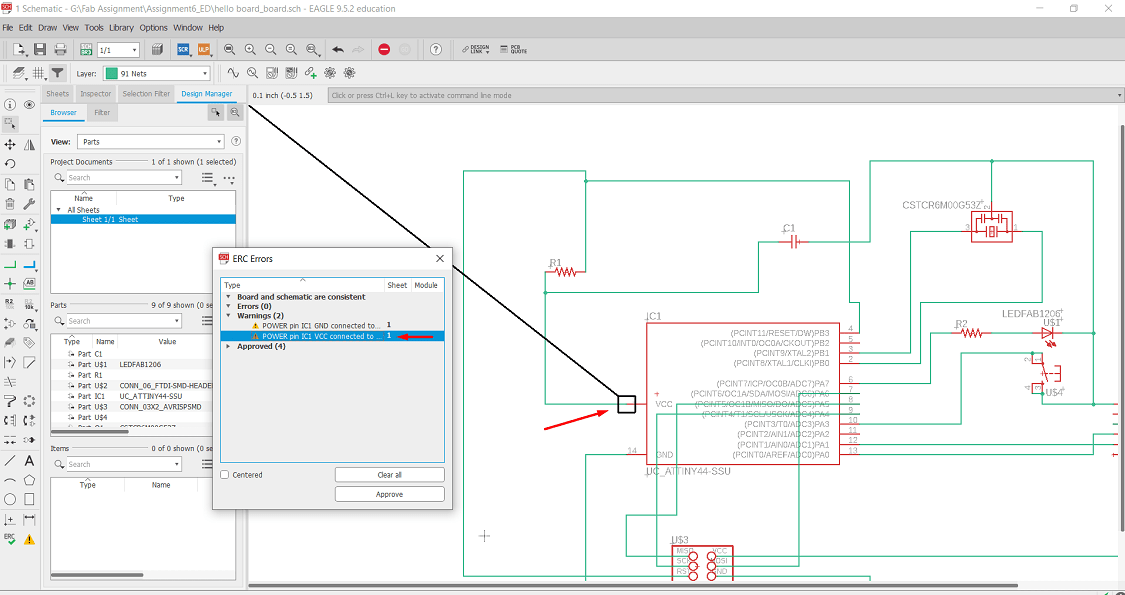
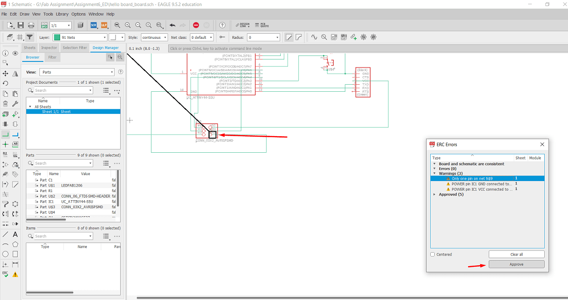
Now all the errors are resolved.
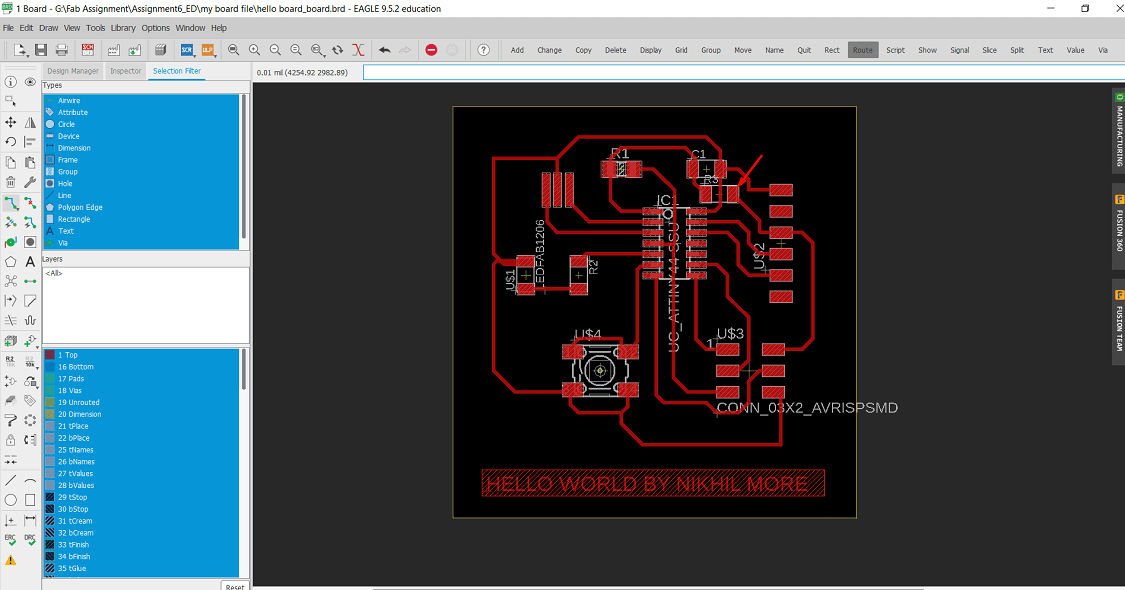
Again i have tried for autorounting. But its not functioning. I have tried to resolve this issue but did not resolved. Then i decided to go for manual rounting. Now i start manual rounting
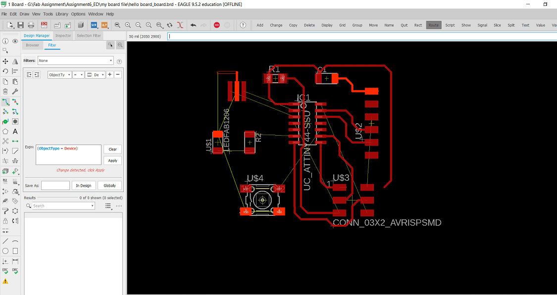
There is issue of way for one path. so i made small changes in schematic diagram. In ATtiny44 IC the PA and PB ports are input/output so its possible to change the pin in between this ports. Also the resonator is connected GND(Ground) of IC.
The board is ready now. I am adjusting the border of the board by clicking the move button on left side.
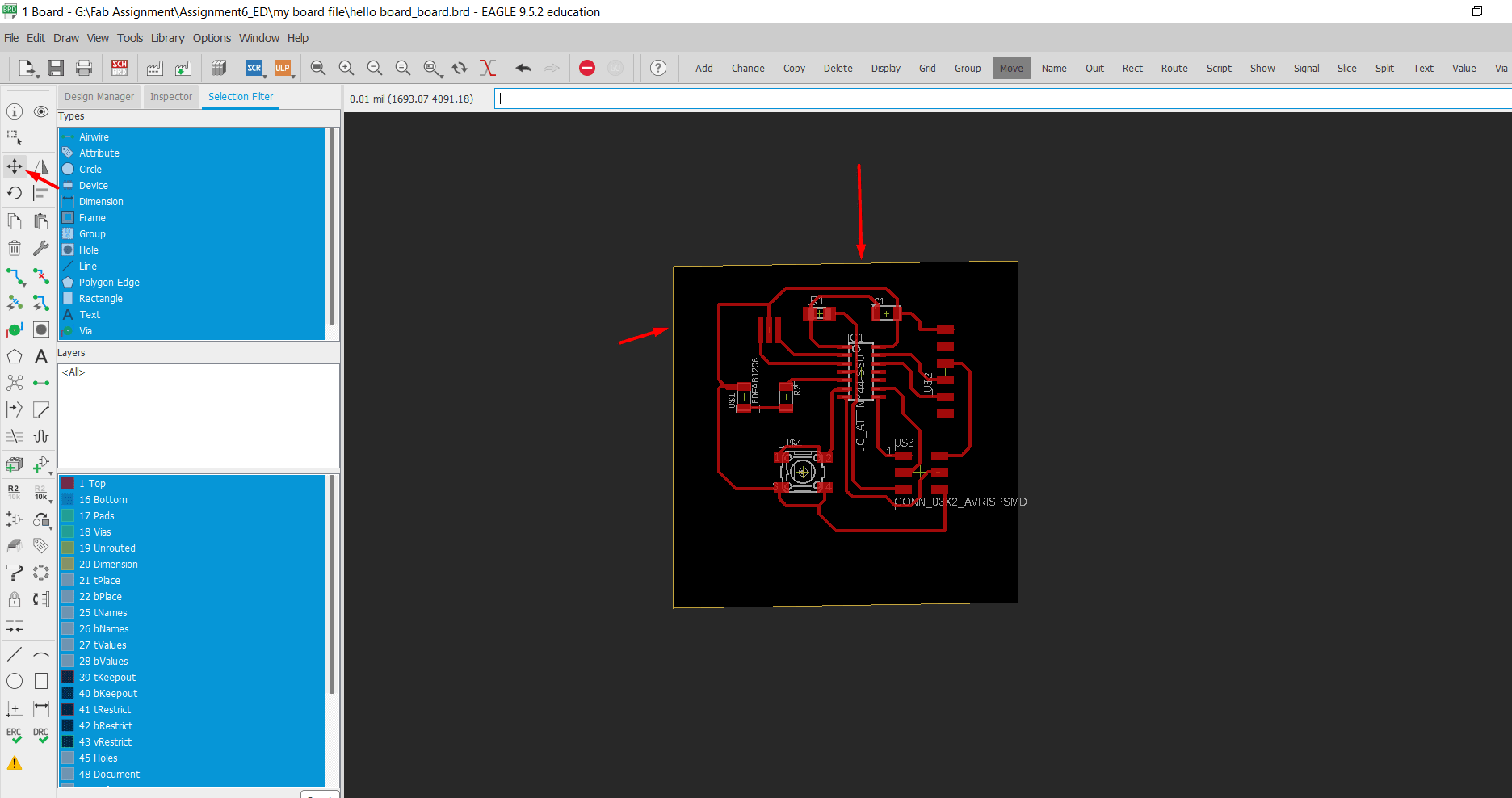
Added my name and board name by clicking on text option on the left side.
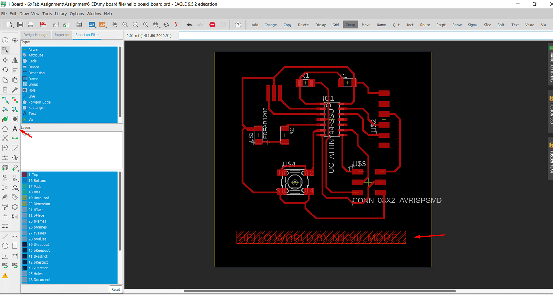
After brainstorming for long time still there is one jumper in the circuit, there is a need of wire to connect. so i talk with my instructor about this issue He suggest me to use 0 ohm resistor, so added this one in schematic diagram and make this changes on board.
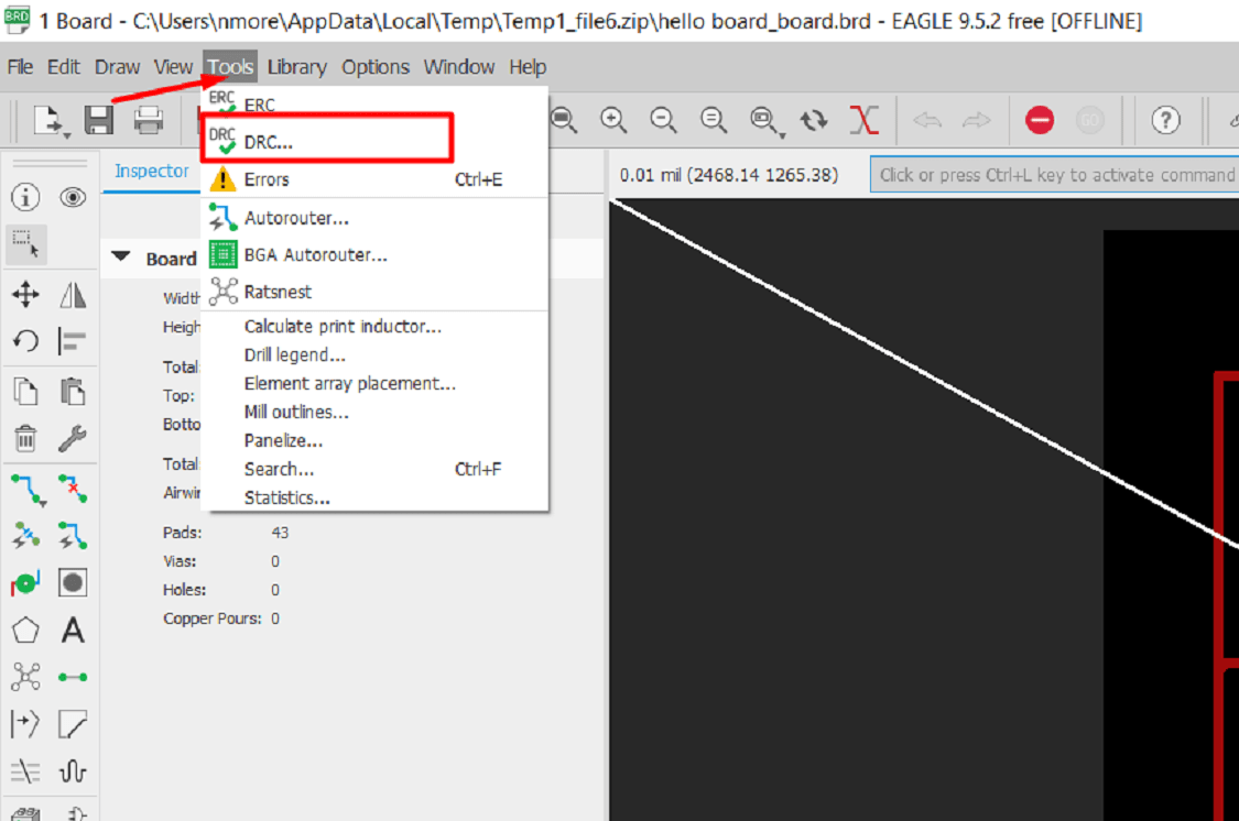
Before to export the design, we have to run a Design Rule Check (DRC). Design Rule Check allows us to establish a set of boundaries for trace widths, component spacing, via diameters, etc.
It’s only after you have all of these rules set up that we can then go about completing our design process, knowing that any issue with these manufacturing-specific constraints will be flagged in Autodesk EAGLE when we run our DRC.Lets go through this step.
Step 1: Select the DRC tool on the left-hand side of our interface to open the DRC Setup dialog.
The DRC windows will get open.
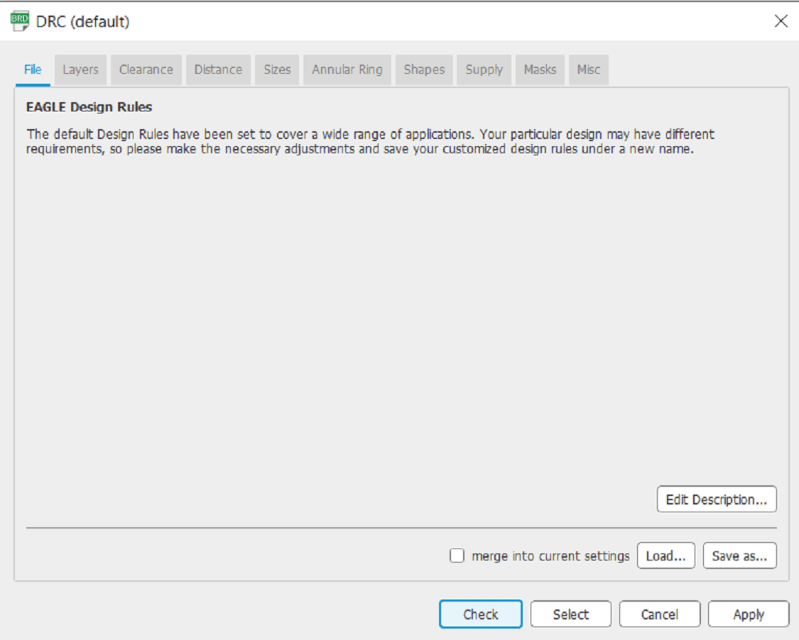
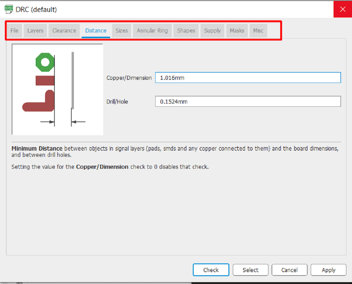
Now there are the two way, whether to go with default setting or change it as per requirement. Here we go with default setting. Lets check all the specificatio once.
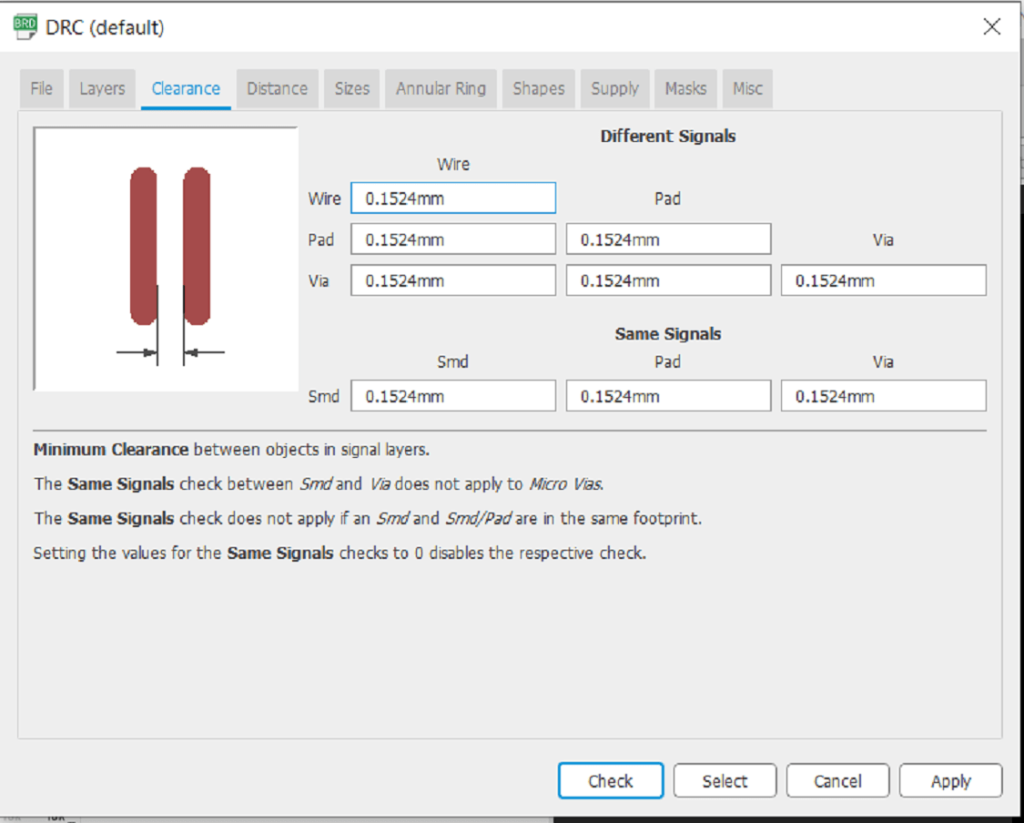
Take a minute to check out the default rules set here in all of the available tabs. When it done, then select the Check button to run our Design Rule Check.
Then click on check button. Its show 9 error and 2 warning. lets check this error and warning,by clicking on it.
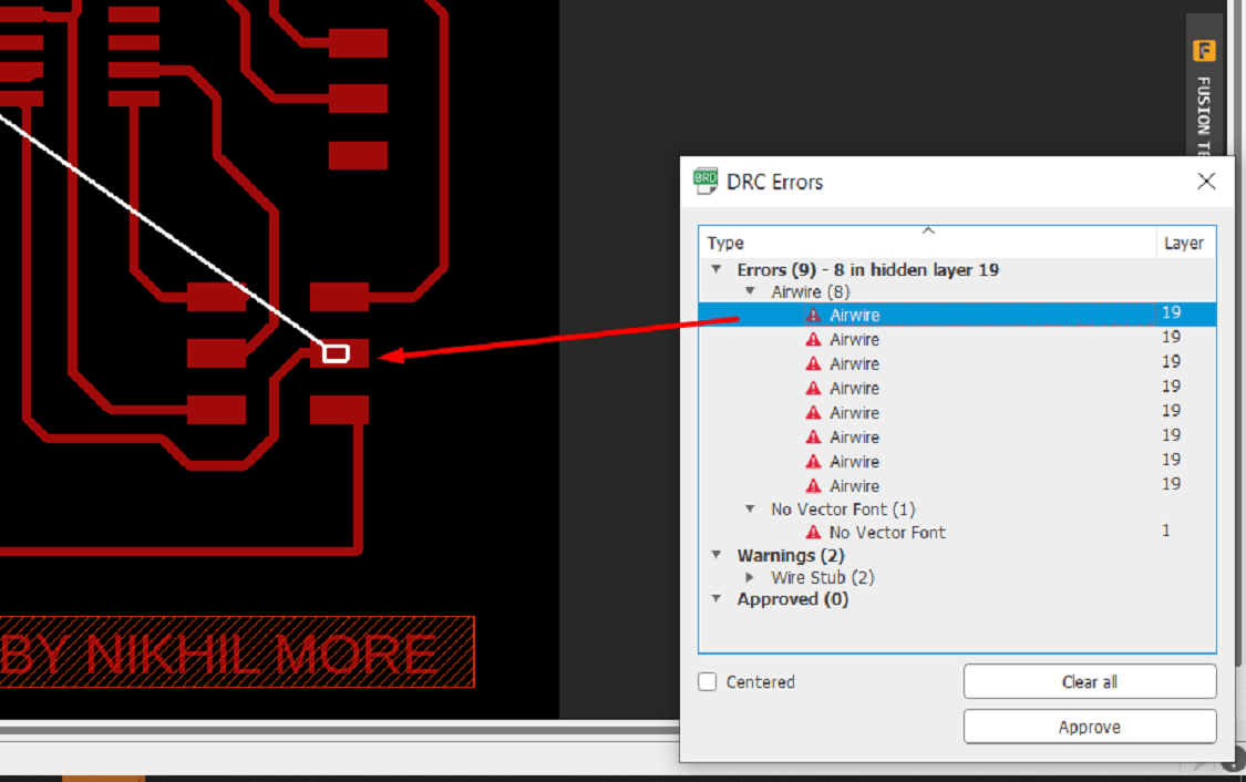
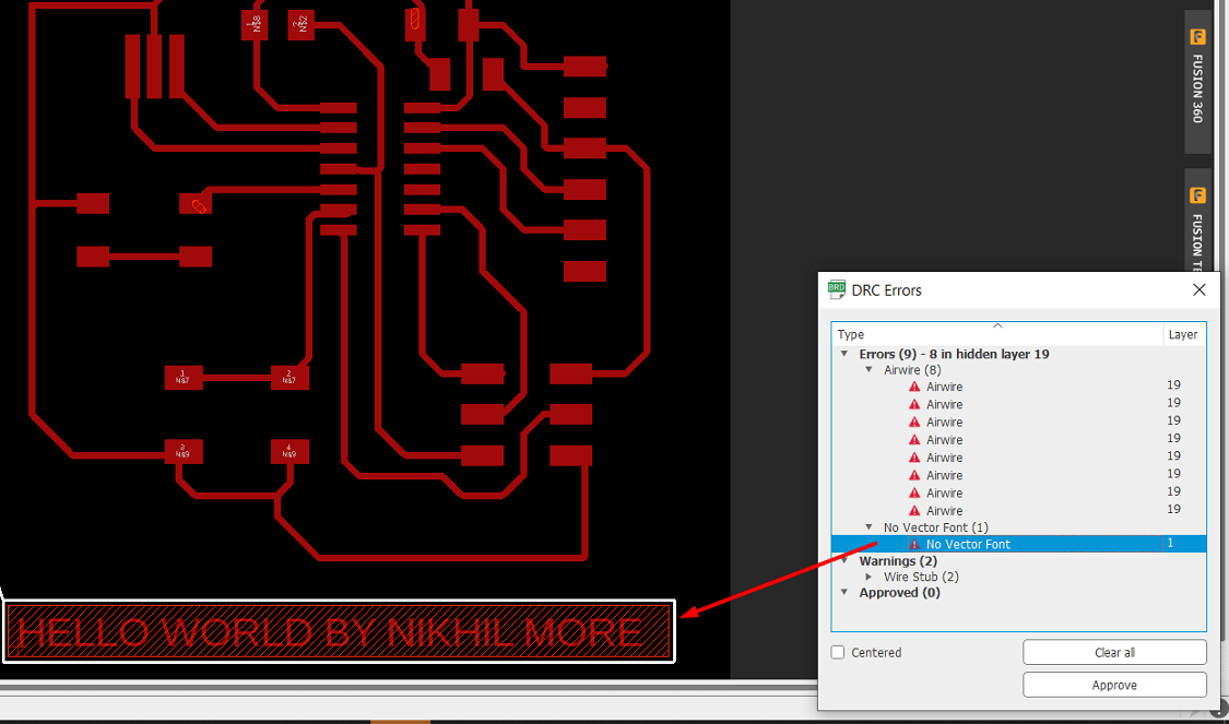
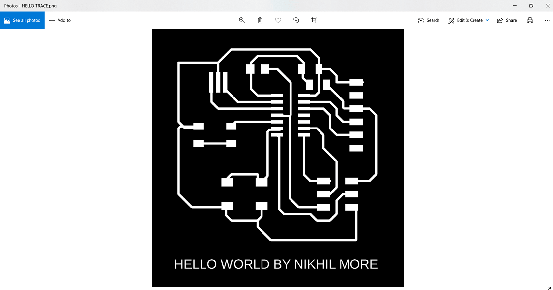
When I have zoom the image, it shows the airwire, which is drawn mistakely, so I have remove it, by cliking on it and aprrove the "No vector font".Now its time to export the image, so I have made layer setting to erase the name of components from the top of PCB
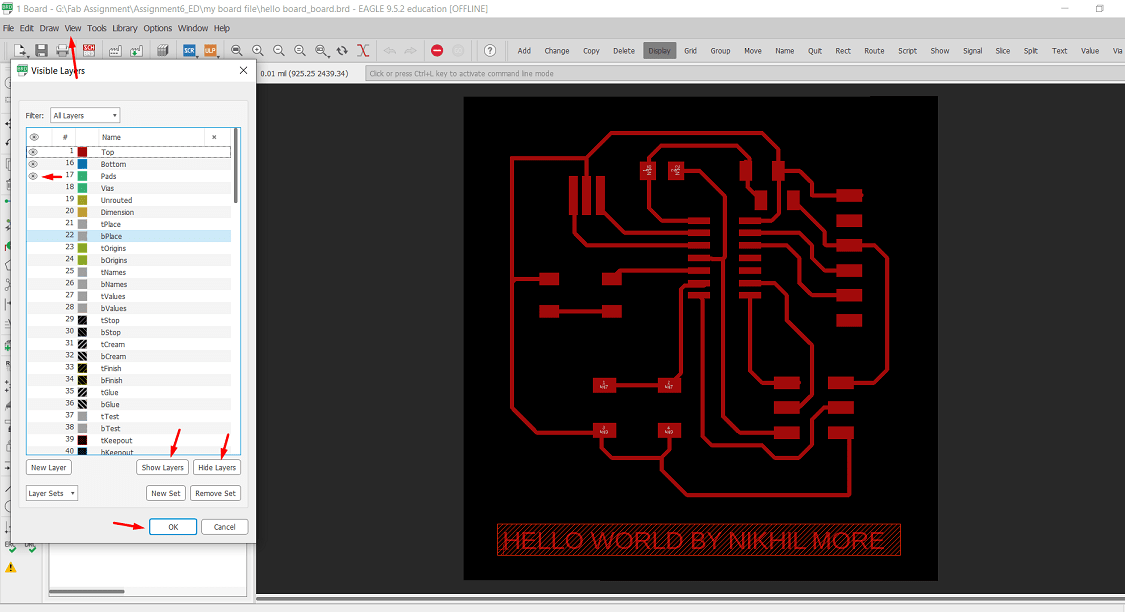
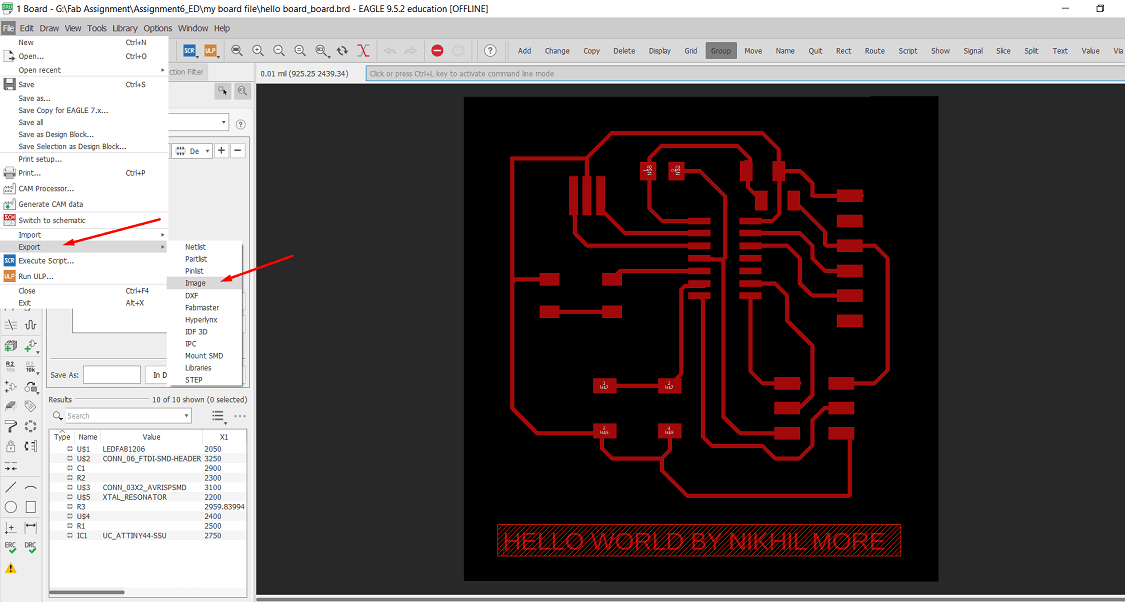
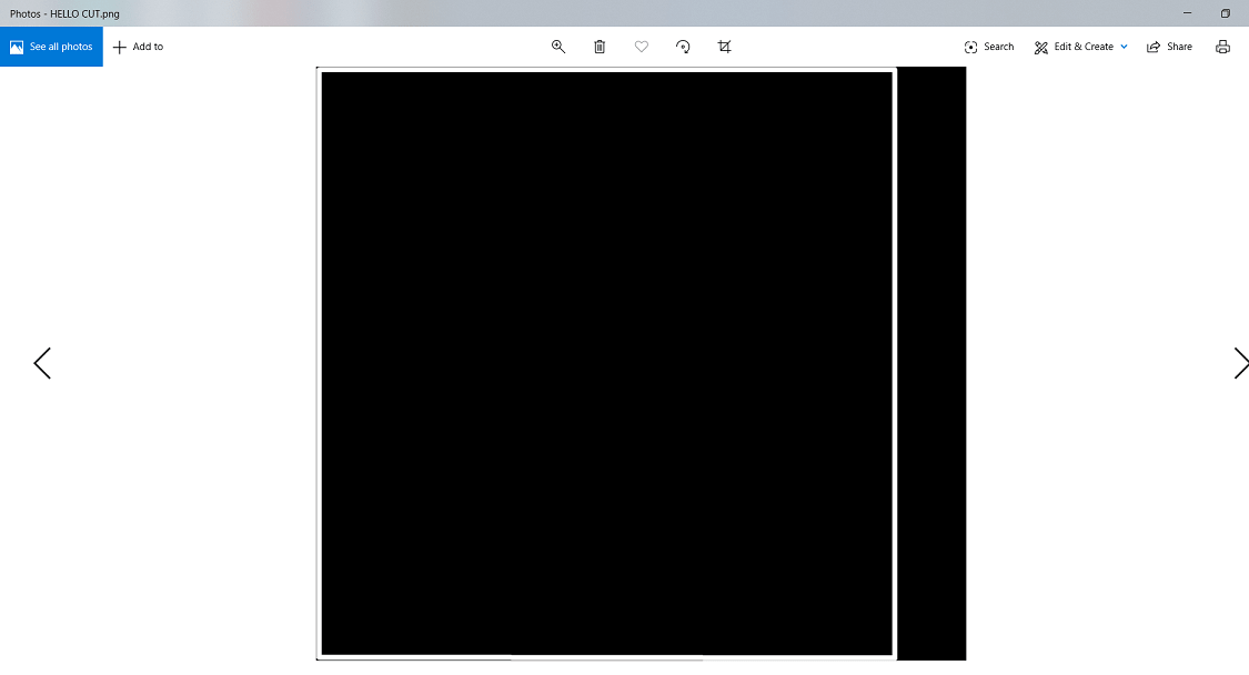
Click file menu>export>image>image setting>ok. Same i have exported the png image of border also.By doing changes in layer i have exported the image for cut also.
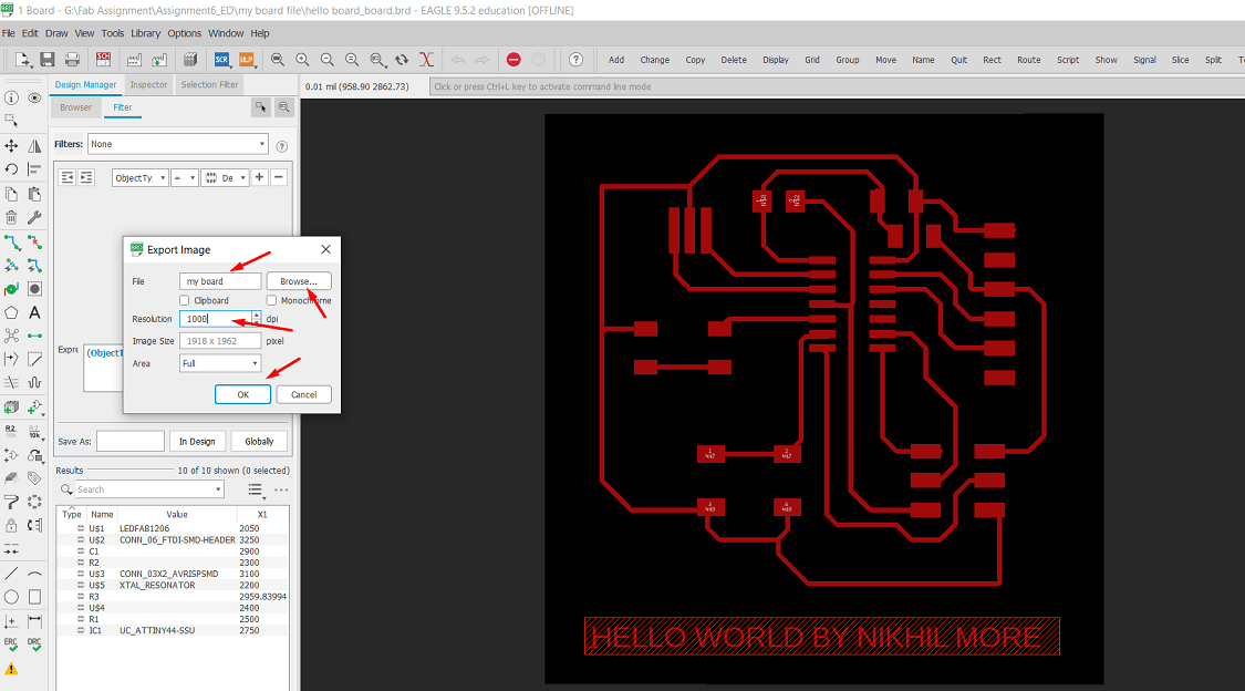
The final png image for milling is this.
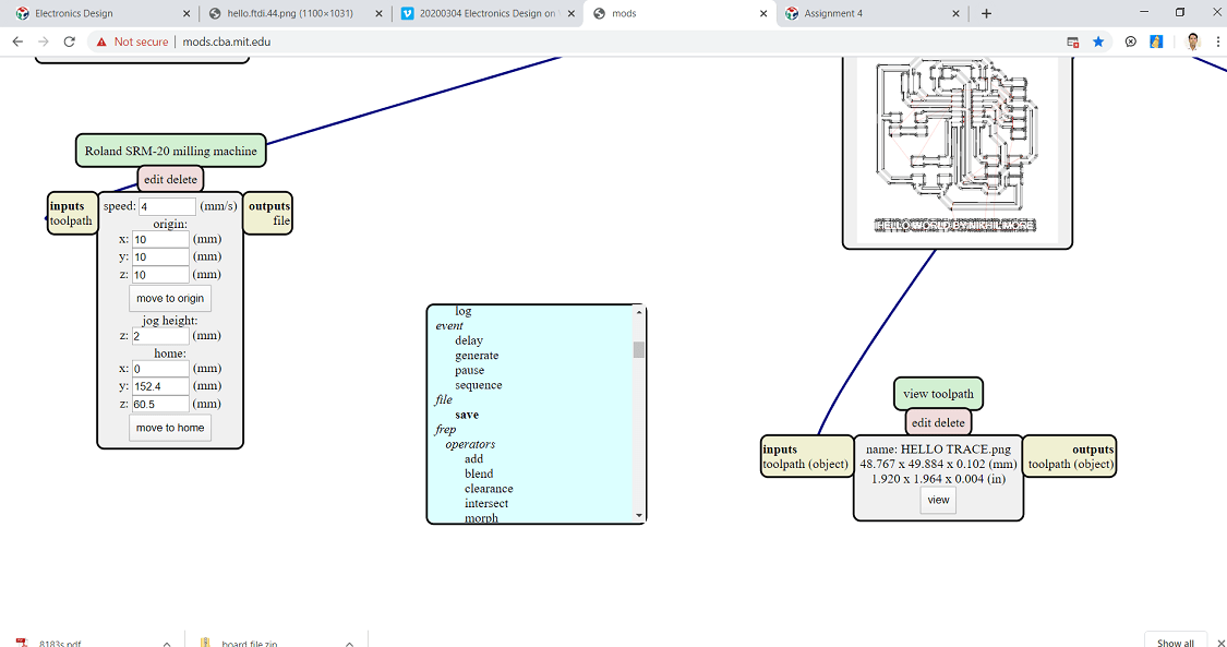
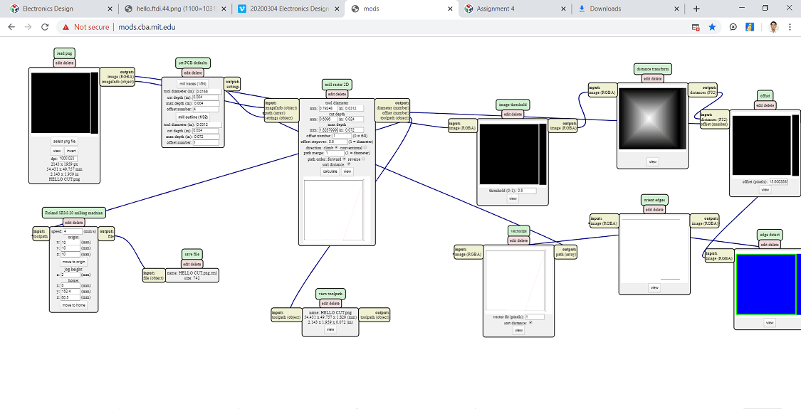
The SRM-20, milling machine read the rml file. so i have to convert the png image into rml file. so i used modes provided by Fab Academy
The details of "how to use the modes" that i have explained in Assignment4.
Open the modes>select the png file.
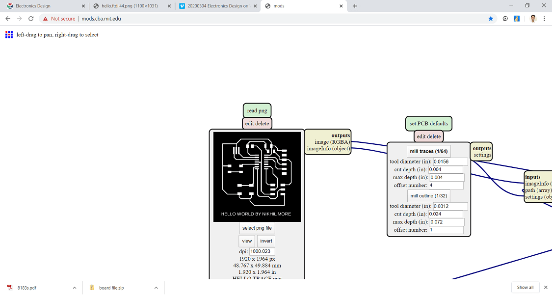
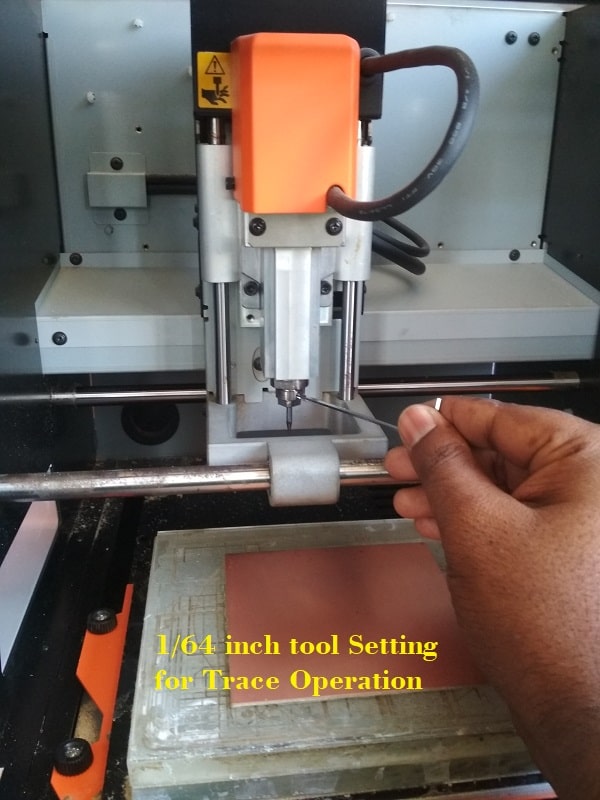
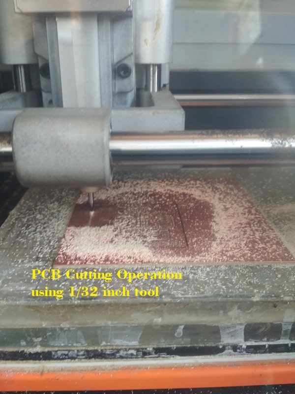
Select the tools (For trace 1/64 inch tool and for cut 1/32 inch tool) and click on calculate
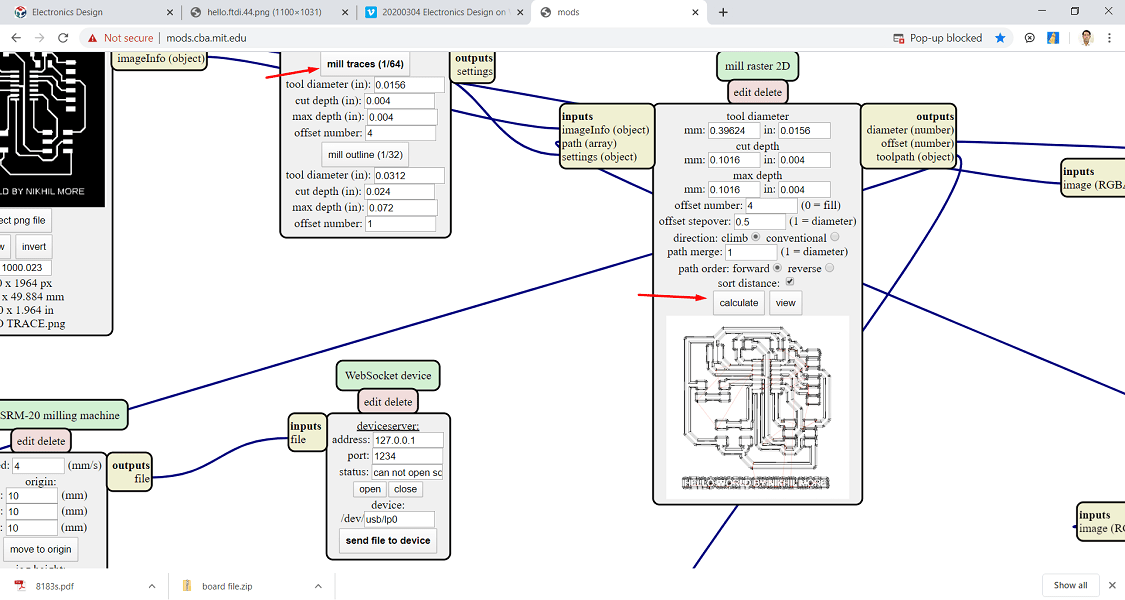
Add new model for save the file>connect the input of this model to output of milling machine>save the file
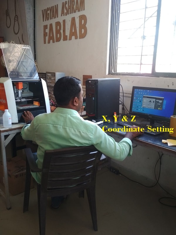
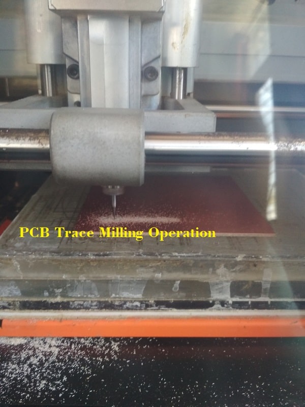
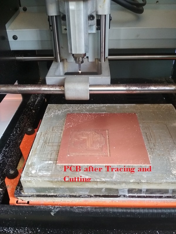
PCB Milling
The PCB milling is done on the SRM-20 milling machine. The following images shows the different process during PCB milling
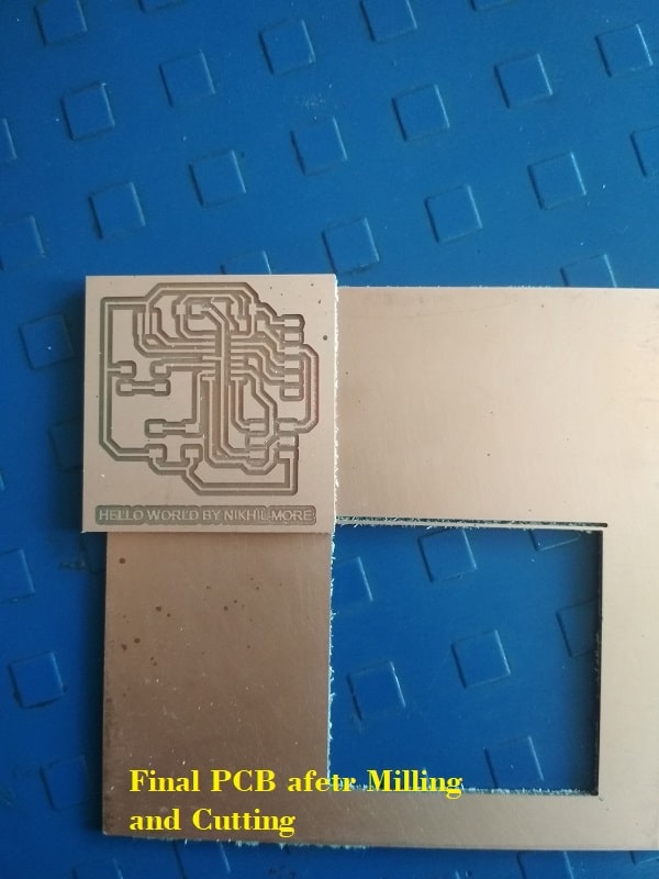
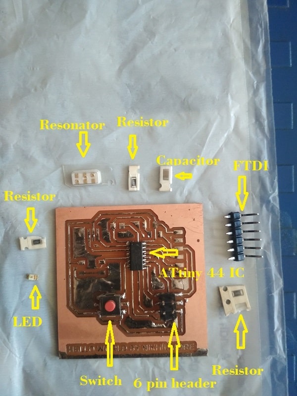
Components Selection and Soldering
For component selection i refer the Fab Academy Board. The following components i have taken
1. ATtiny44 IC - 01 Nos.
2. Resonator 20M - 01 Nos.
3. FTDI 06 Pin - 01 Nos.
4. 6 pin header - 01 Nos.
5. Capacitor - 01 Nos.
6. Resistor (For capacitor)100 Ohm - 01 Nos.
7. Green LED (25mA) - 01 Nos.
8. Resistor (For LED) 5V/0.025A=200 Ohm But in 499 Ohm resisitor is available - 01 Nos.
9. Button (4pin) - 01 Nos.
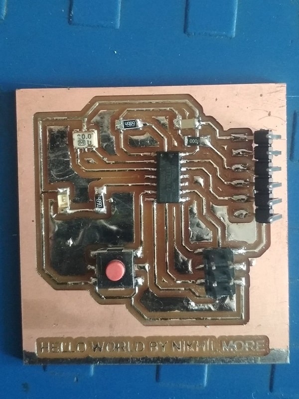
This components is soldered on the PCB.
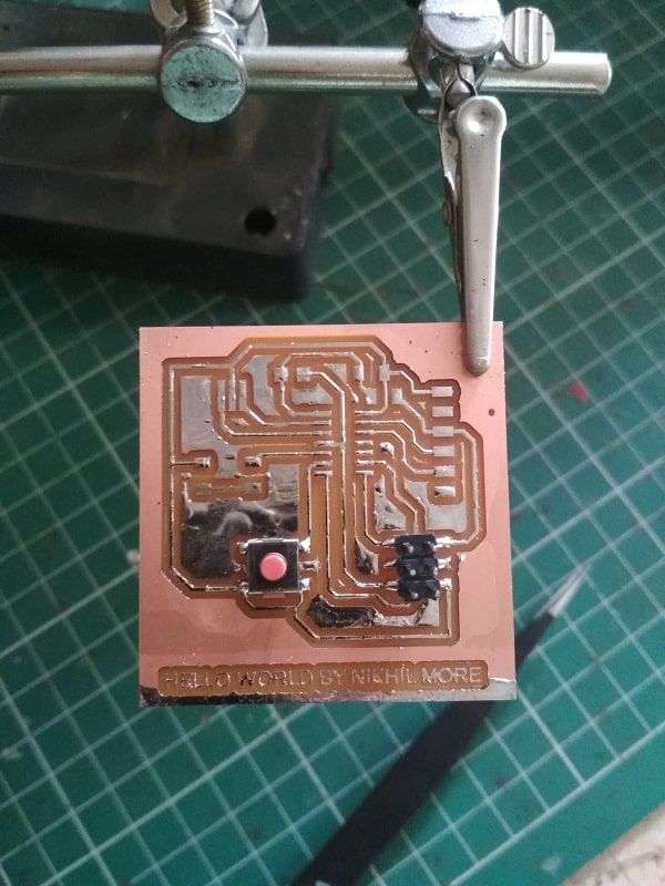
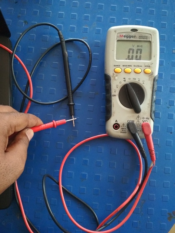
Connections and Conductivity Testing
The conductivity of the board is tested with help of Megger make Multimeter. Everything is fine
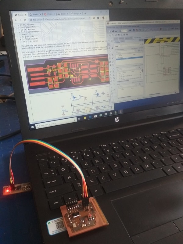
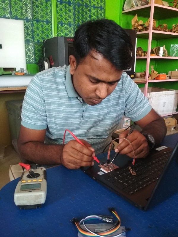
Programming and Testing of Board
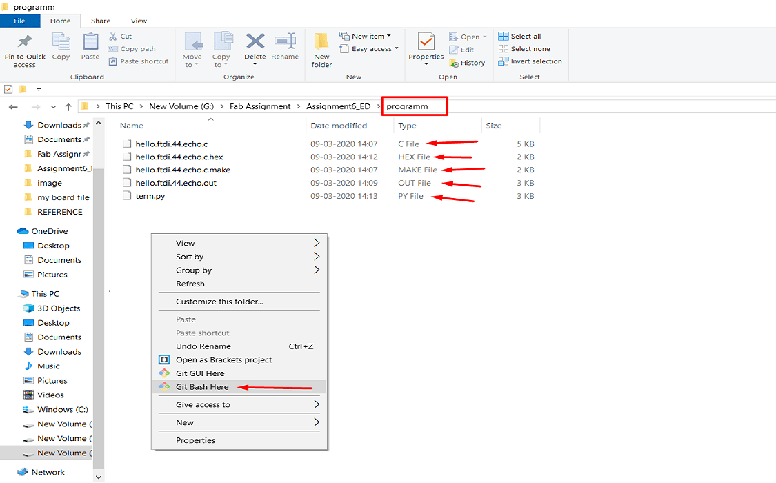
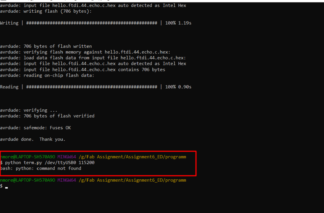
For programming firstly download the c file and make file from the page of embedded programming of Fab Academy. With ATtiny44 the programming file is given This file is downloaded in a separate folder.
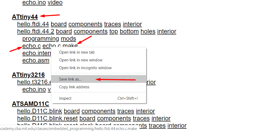
Now i have open the GitBash at there. so this file will get open in Git Bash
Then applying this command in Git bash given on the following page
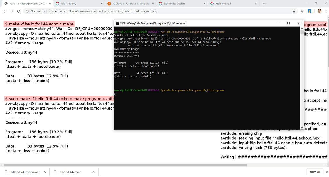
So when i am applying second and third command, one errors is showing on Git Bash, which is off connections error. Now i have to check all the connections double.
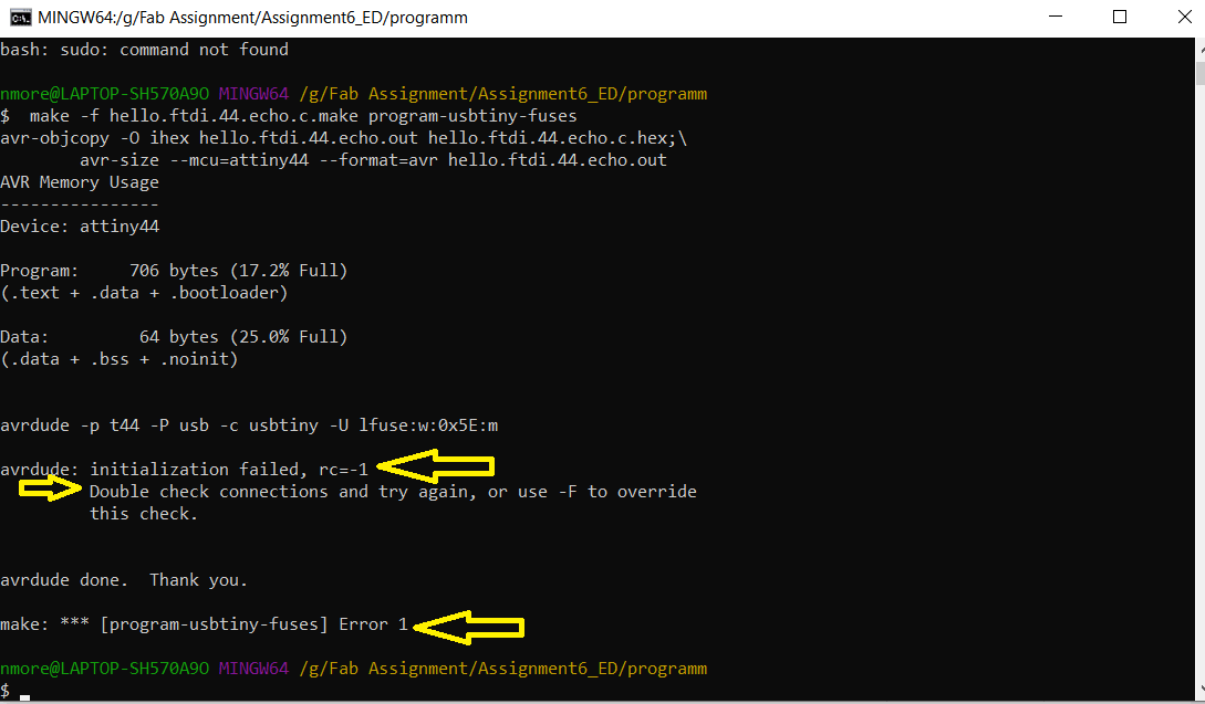
My instructor Mr. Suhas Sir help me to solve this issue, he found one mistake of components in my board, At the time soldering, i have wrong resistor, actually it required of 100 ohm and i used 499 ohm. so i replace it. Then i have doing the finishing again on soldering. Then again connected and started programming
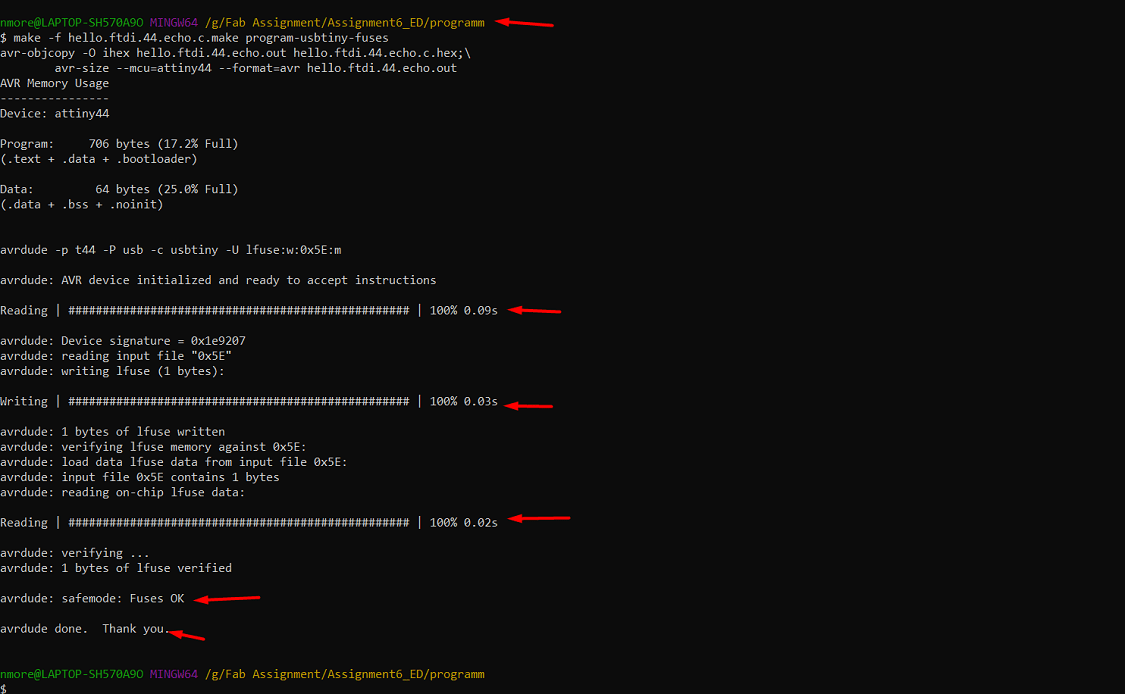
The first command is running ok, now the applying second and third command. It is also ok
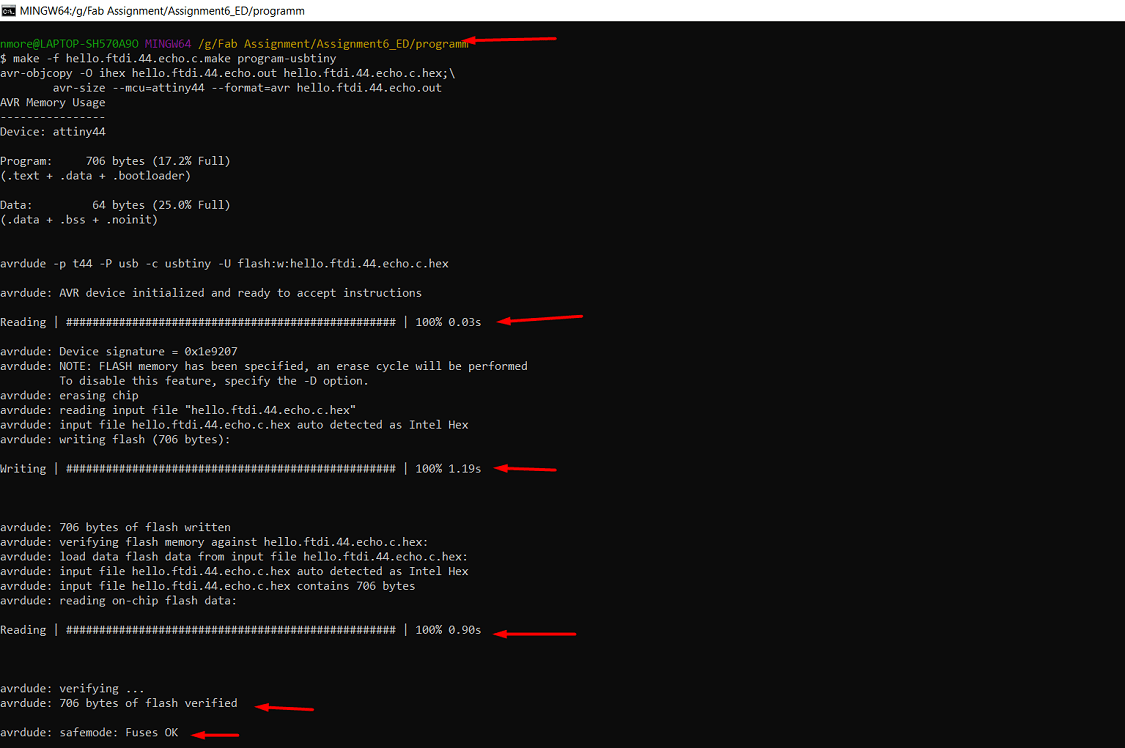
The Green LED is blinking after succesfull programming.

What problem i have faced?
1. At the time of board design, at one place for one path has no way to draw. I tried number of ways to draw it, but not
posible by me. so i used zero ohm resistor at there. It was taking long time to solve this issue.
2. At the time of programming, it will shows one error of connections, so here again i have made connections.
3. Also by mistakely i have soldered one wrong resisitor, that i have to replace
Group Assignment
The task for group assignment is to use the test equipment in our lab to observe the operation of a microcontroller circuit board. The test equipment available in our lab is regulated power supply, digital multimeter and oscilloscope. Here we test our group member Snehal microcontroller and observe its operation. The more details about group assignment is available on our group member (Tejaswini) website. So lets click on the give link for more details. Electronics Design Group Assignment
What i learn?
I am learn about
1. To use the Eagle Software for circuit board design
2. Different components use in Electronics Circuit
3. Specification and selection of components for circuit
4. Microcontroller and its pin configurations.
5. Machining, soldering and conductivity testing of board
6. Programming and testing of board from given program
7. To test the microcontroller using different test equipment such as regulated power supply, digital multimeter and oscilloscope etc.
Go to the top
Back
Assignment 8: Computer-Controlled Machining
Computer-Controlled Machining is the use of software and machinery to automate a manufacturing process.

Fab Academy Course on Digital Fabrication by Nikhilkumar More is licensed under a Creative Commons Attribution-NonCommercial 4.0 International License.
Based on a work at http://fabacademy.org/2020/labs/vigyanashram/students/nikhilkumar-more/.
Permissions beyond the scope of this license may be available at http://fabacademy.org/2020/labs/vigyanashram/students/nikhilkumar-more//contact.html