Computer Controlled Cutting
Week Task
group assignment:characterize your lasercutter's focus, power, speed, rate, kerf, and joint clearance
individual assignment:cut something on the vinylcutter design, lasercut, and document a parametric construction kit,accounting for the lasercutter kerf,
which can be assembled in multiple ways, and for extra credit include elements that aren't flat
Introduction
The Computer controlled machining is a subtractive manufacturing process which typically employs computerized controls and
machine tools to remove layers of material from a stock piece—known as the blank or workpiece—and produces a custom-designed part.This process is suitable for a wide range
of materials, including metals, plastics, wood, glass, foam, and composites, and finds application in a variety of industries
In the last assignment, the different tools are used for 2D and 3D design. In this assignment, we have to cut this 2D design by using different cutting tools.
The commonly used tools for cutting are knife, laser, plasma,waterjet,hotwire,wireEDM etc.So in this assignment particullary we are studied lasser cutter and vinylcutter. In laser cutting
we have conduted one group assignment and one individual assignment. In group assignment, we have studied about lasercutter's focus, power, speed, rate, kerf, and joint clearance.
Group Assignment
In this week, in group assignment, we have to characterize the lasercutters focus, power, speed, rate, kerf
and joint clearance. We cut different pieces of cardboard by using different speed and power, then optimize the proper speed and power for cardboard.
Then by measuring the cutting dimension, compared it with design dimension, we calculte kerf. The details about Group Assignment is given on our Fab Lab, Vigyan Ashram page
Click here for details about 3-Week Group Assignment
Individual Assignment
In the individual assignment, we have to cut something on Vinyl cutter and make a parametric construction kit by using laser cut machine. So below i have explained this assignment, so,lets see
Laser Cutting
The term LASER is known as Light Amplification by Stimulated Emission of Radiation i.e. device that generates an intense beam of coherent monochromatic
light (or other electromagnetic radiation) by stimulated emission of photons from excited atoms or molecules. Lasers are used
in drilling and cutting, alignment and guidance, and in surgery; the optical properties are exploited in holography, reading barcodes, and in recording and playing compact discs.
The different gases CO2 (10.6 u), fiber (1-2 u), InGaAsP (1-2 u),AlGaAs (600-900 nm), Nd:YAG (1064, 532 nm), Ti:sapphire (650-1100 nm) are used in Laser Machine.
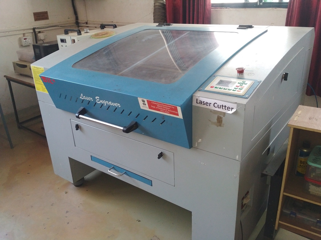
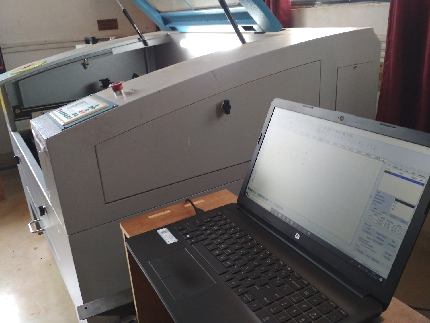
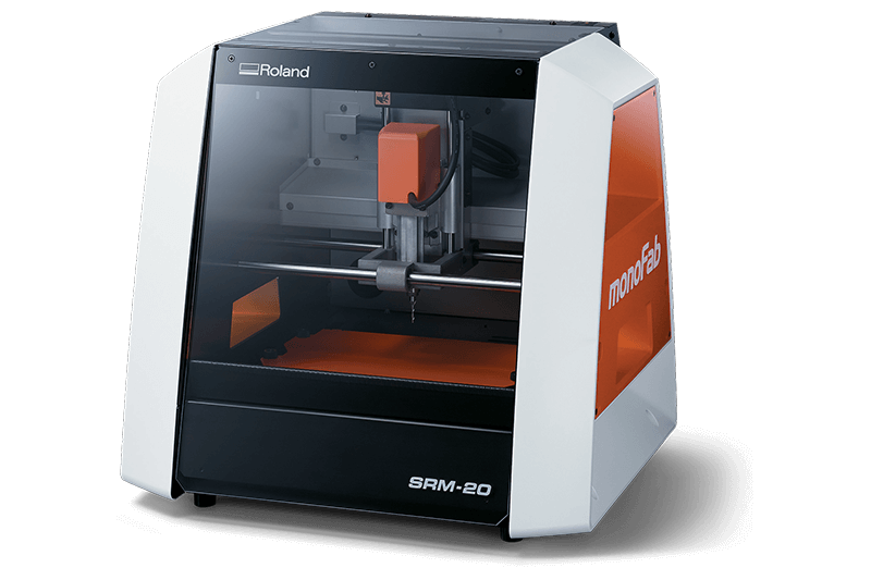
The machine available in our Fab Lab has following specification:
• Model No:1325 – 1318
• Laser Type:Co2 DC Glass laser Tube
• Laser Power:80 Watt
• Processing Area(Bed size):900 x 600 mm
• Working Speed :Adjustable
• Power Supply: Single Phasehase AC 230V, 50HZ
• Software: RDWorksV8
• File Format Supported: .dxf .obj .svg
Parametric Design
The parametric design is created in FreeCAD by using the spreadsheet.The Spreadsheet Workbench allows you to create and edit spreadsheets, use data from the spreadsheet
as parameters in a model,fill the spreadsheet with data retrieved from a model, perform calculations, and export the data to other spreadsheet applications such as LibreOffice or Microsoft Excel. If i want to change the dimension
of the design, then directly i will change it in spreadsheet, the changes will automaticall get active.
The following image shows hows the design of parametric kit is done by using spreadsheet.
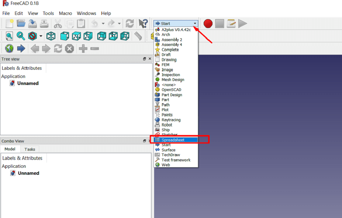
To get started, go to the Spreadsheet workbench>create new spreadsheet
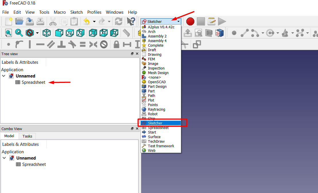
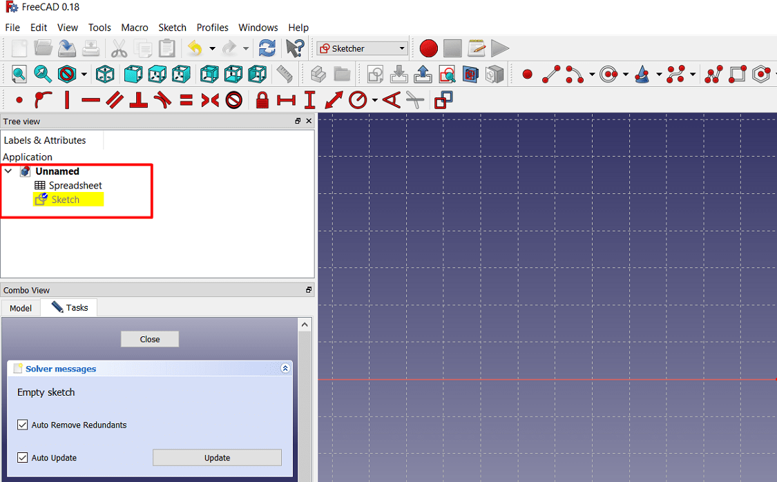
Then select the sketcher workbench and create the new sketch
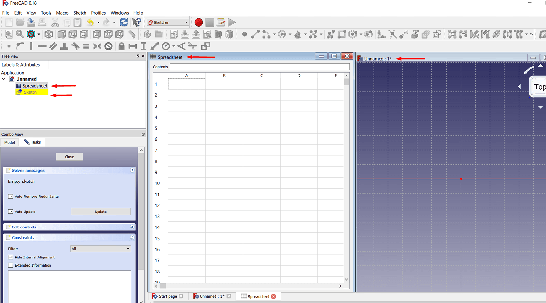
Then open the windows menu>select Tile
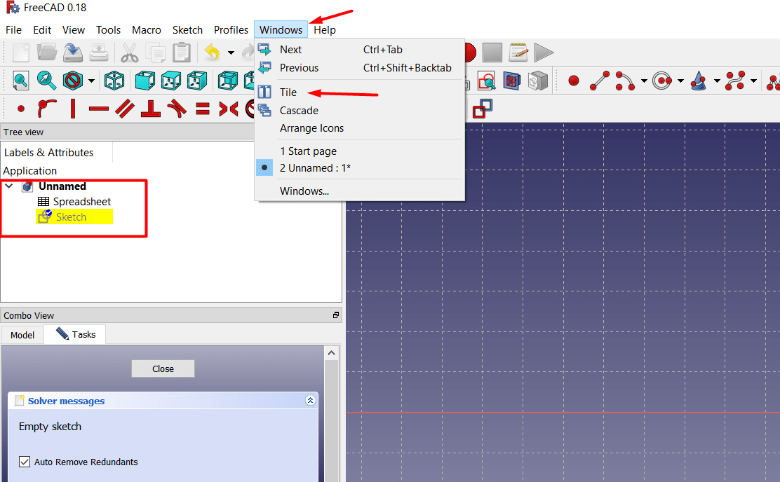
Then Tile menu open the both workbench in a single screen, so that we will used both the workbench at the same time
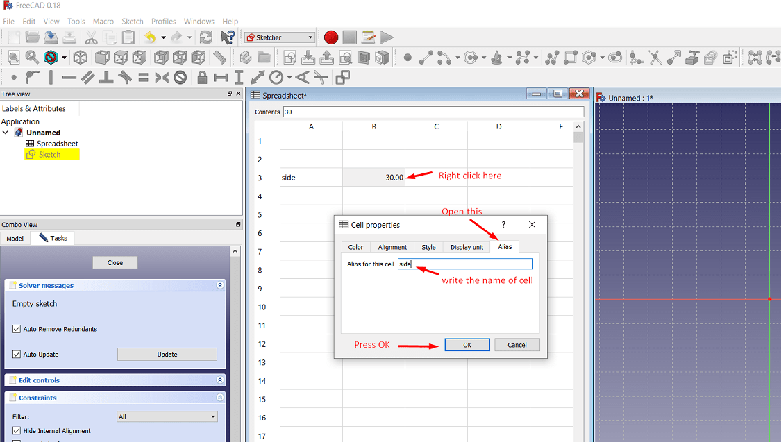
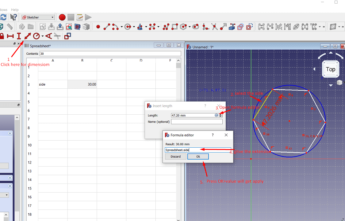
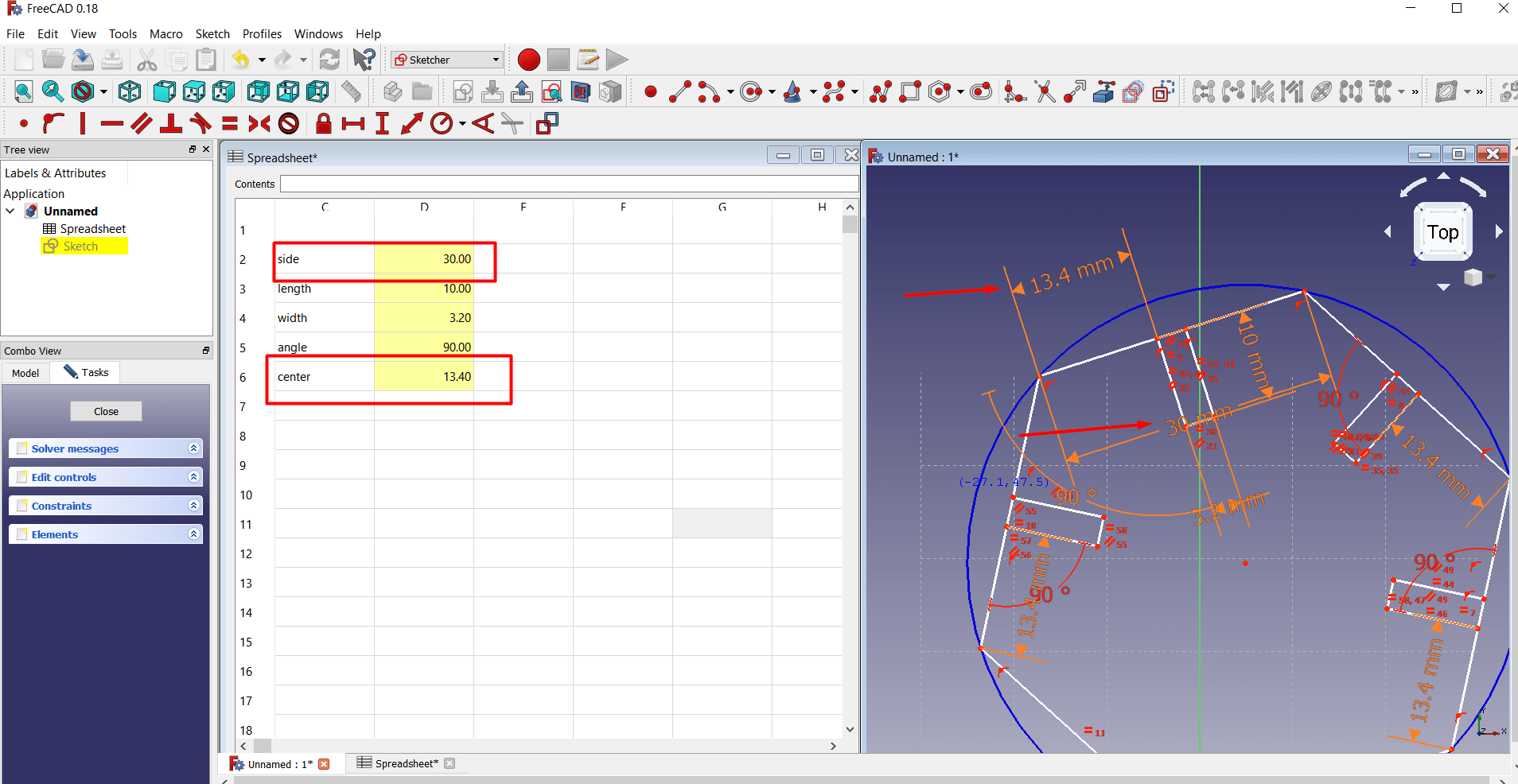
Then put the dimension for the side of hexagon>click right on the value>gove the cell property>i.e. "side" here>then press OK
Then in sketcher workbench, draw the hexagon>give the dimension to the side using the value from the spreadsheet
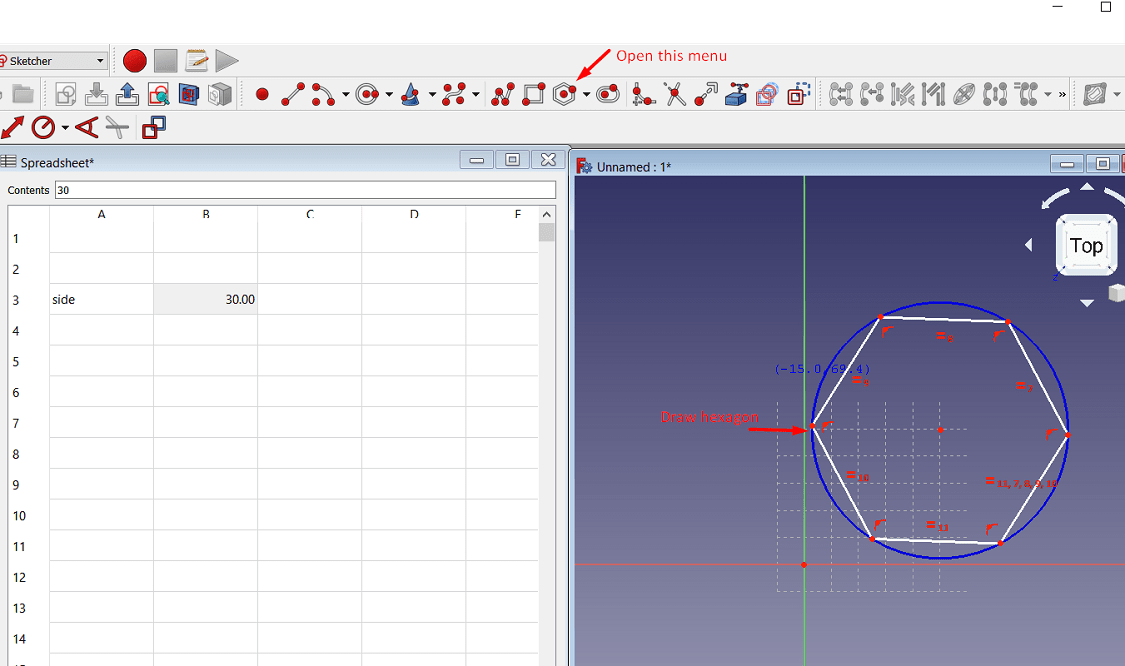
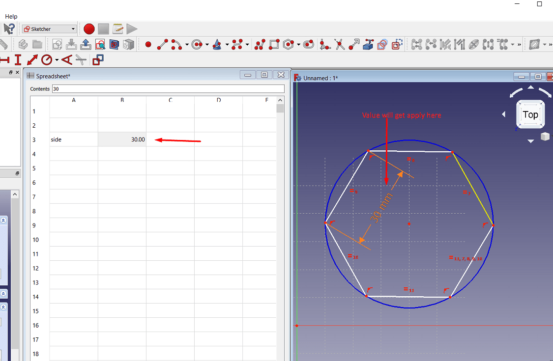
The value will get apply to the side of hexagon. If I need to change the dimesion of side>then change the value in spreadsheet>it will automatically get apply to the skecth.
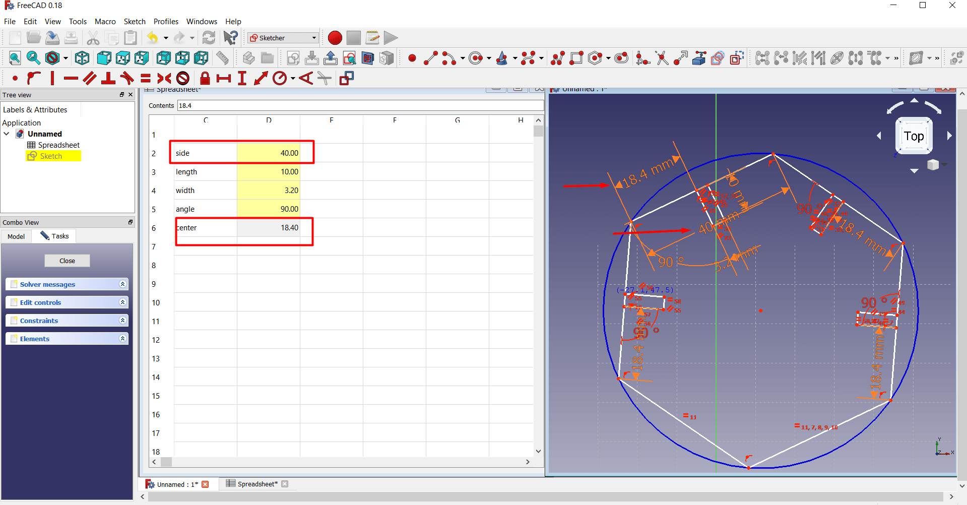
Simillarly put the value of other dimension for the sketch> use the same method to apply the dimension from spreadsheet
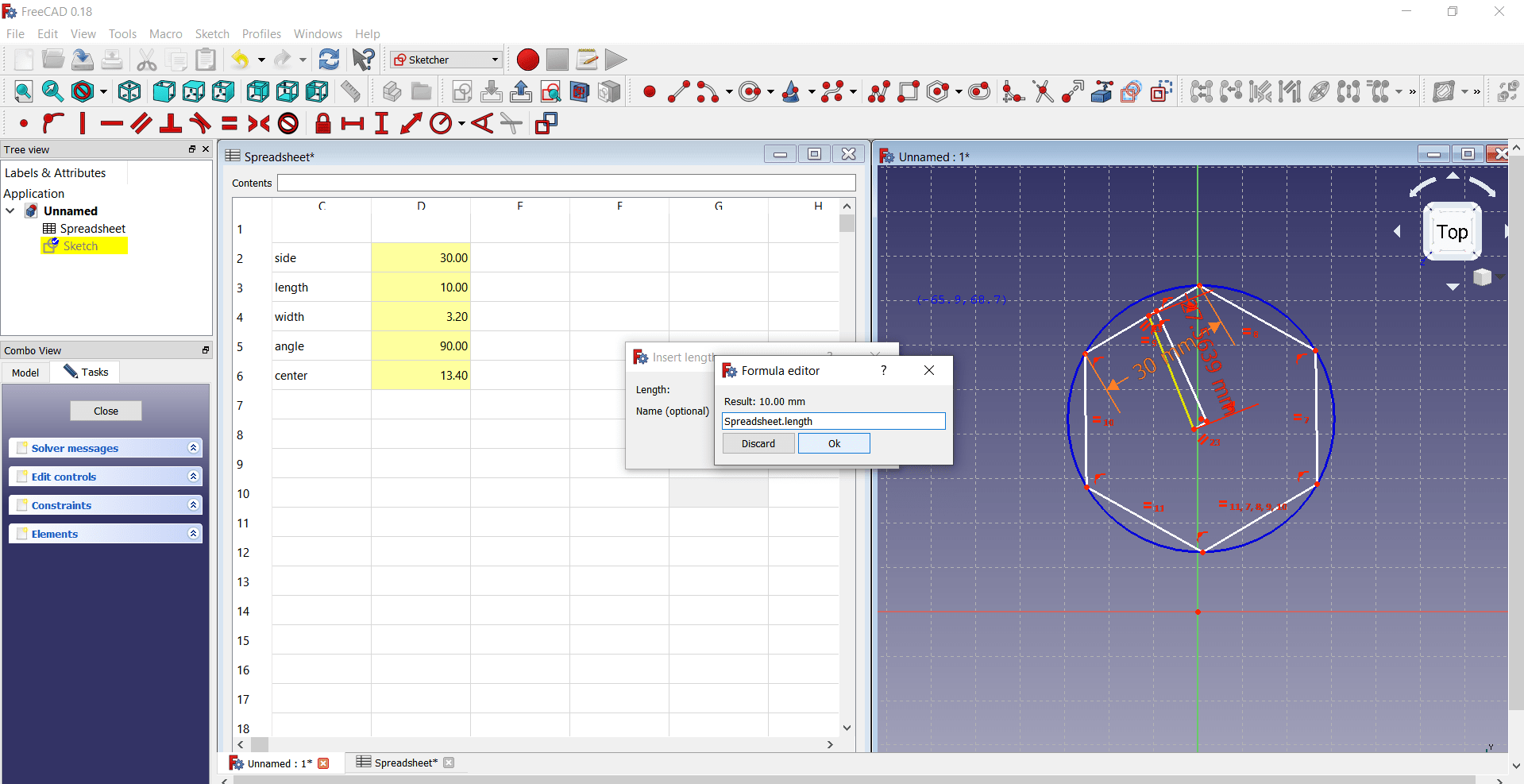
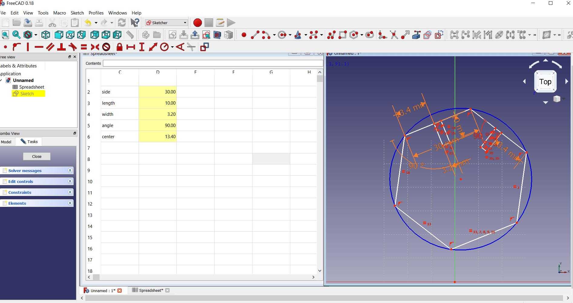
Following image shows hows the changes in dimesion will be done in spreadsheet and how it is activated
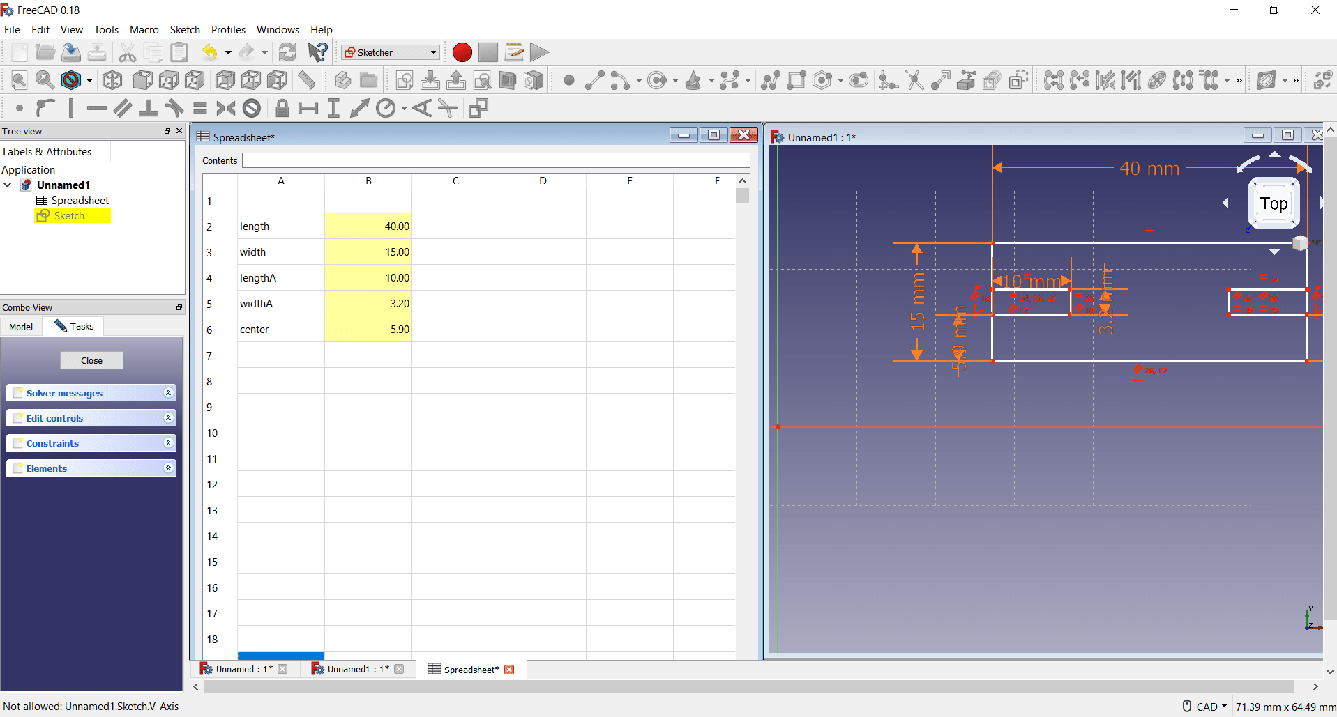
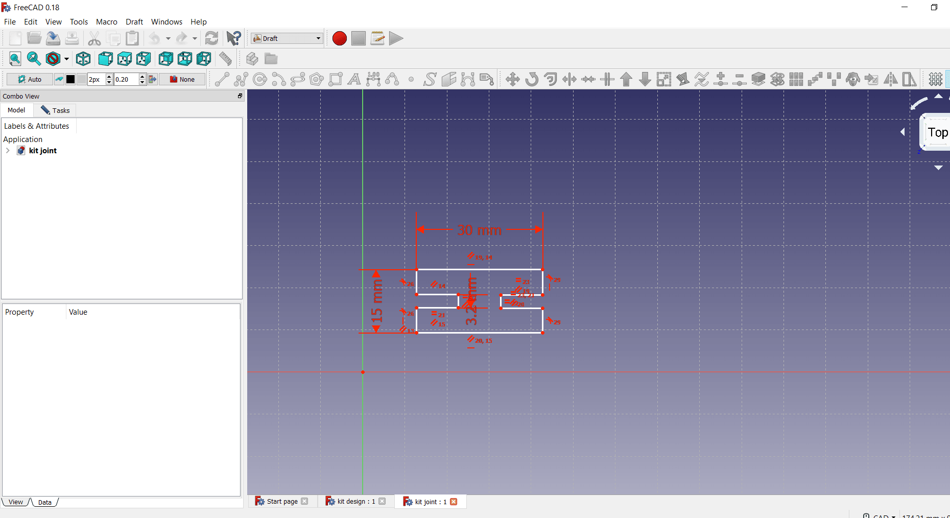
This is a joint in parametric kit designed by using spreadsheet.
Now this design is imported in Laser machine software i.e. RDWorksV8. so lets see how it is imported from FreeCAD
Software
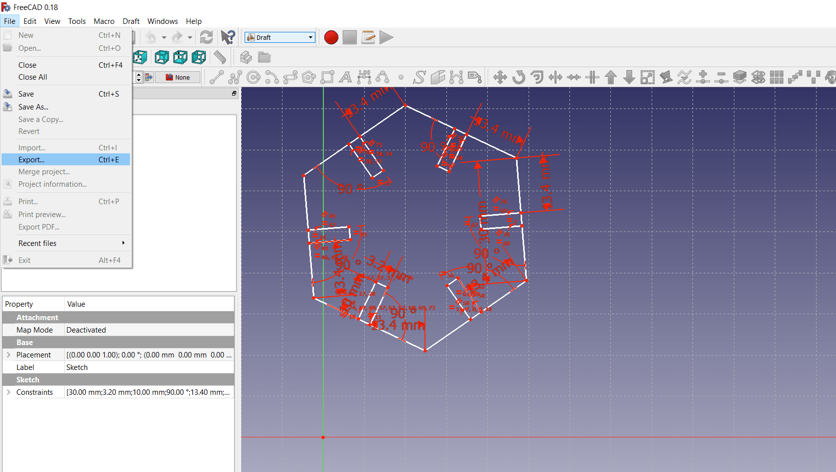
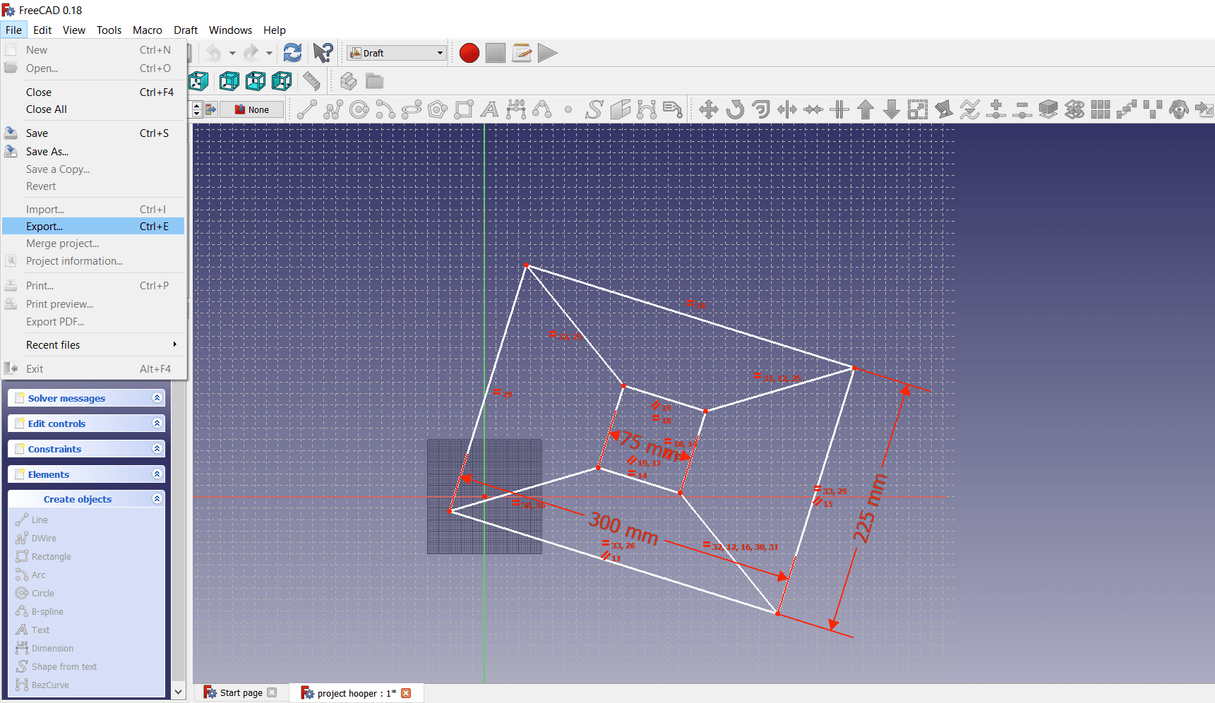
Firstly select the Draft workbench in dropdown menu
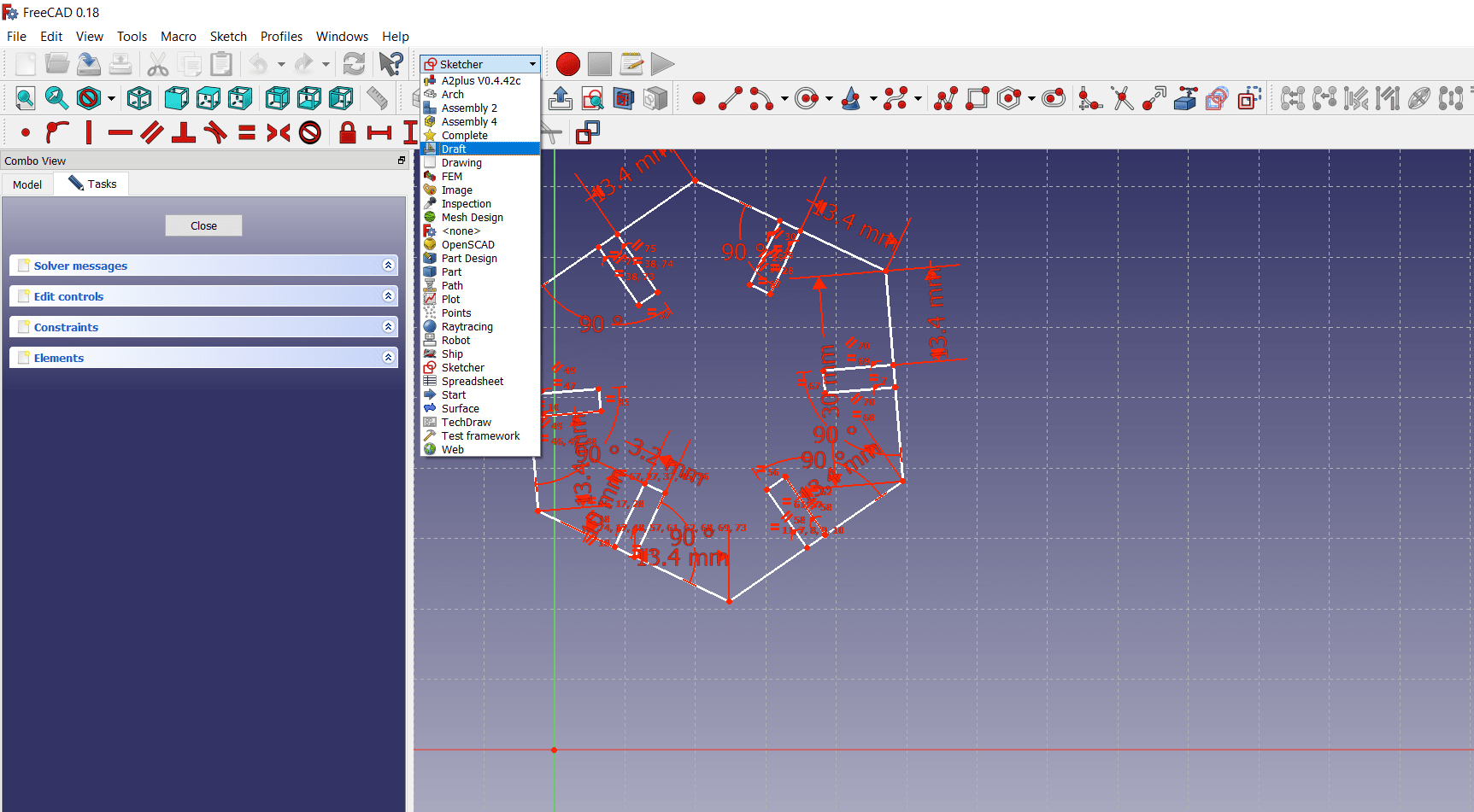
Then export the image, save the image in .dxf formatt at anywhere
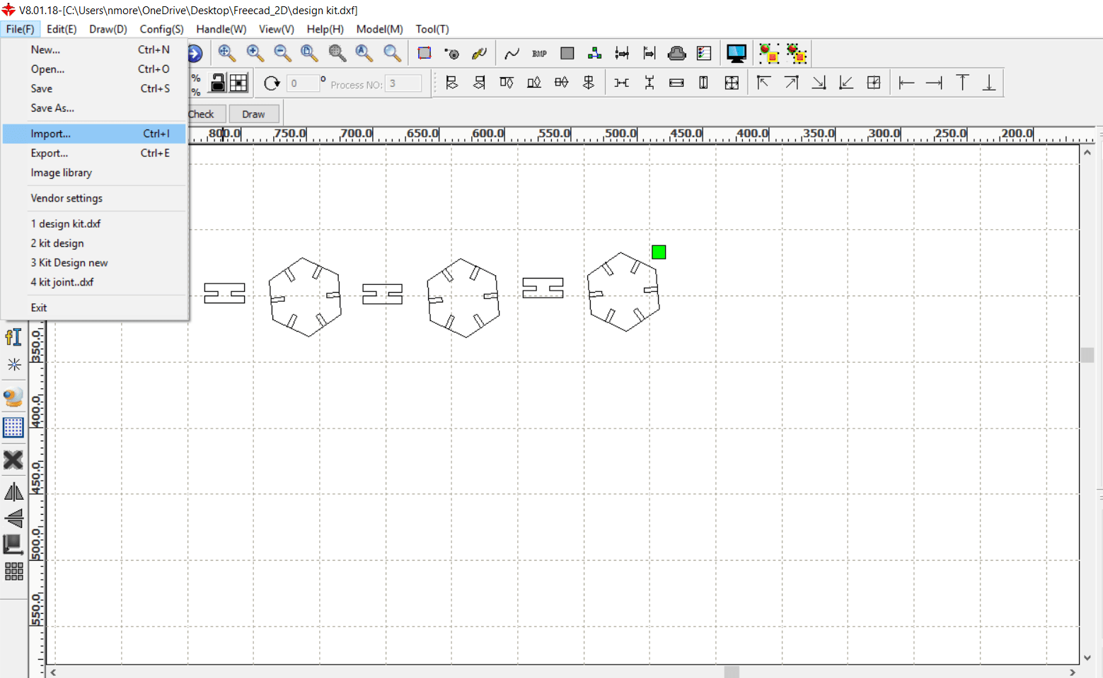
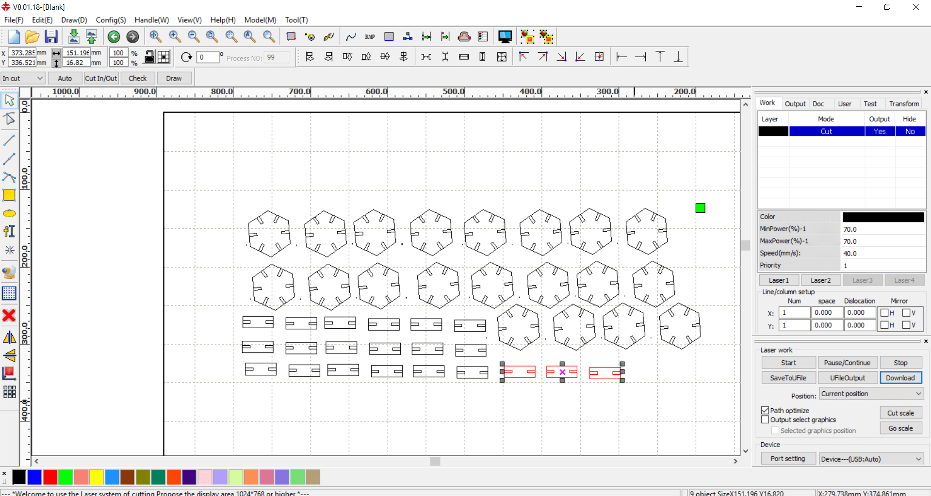
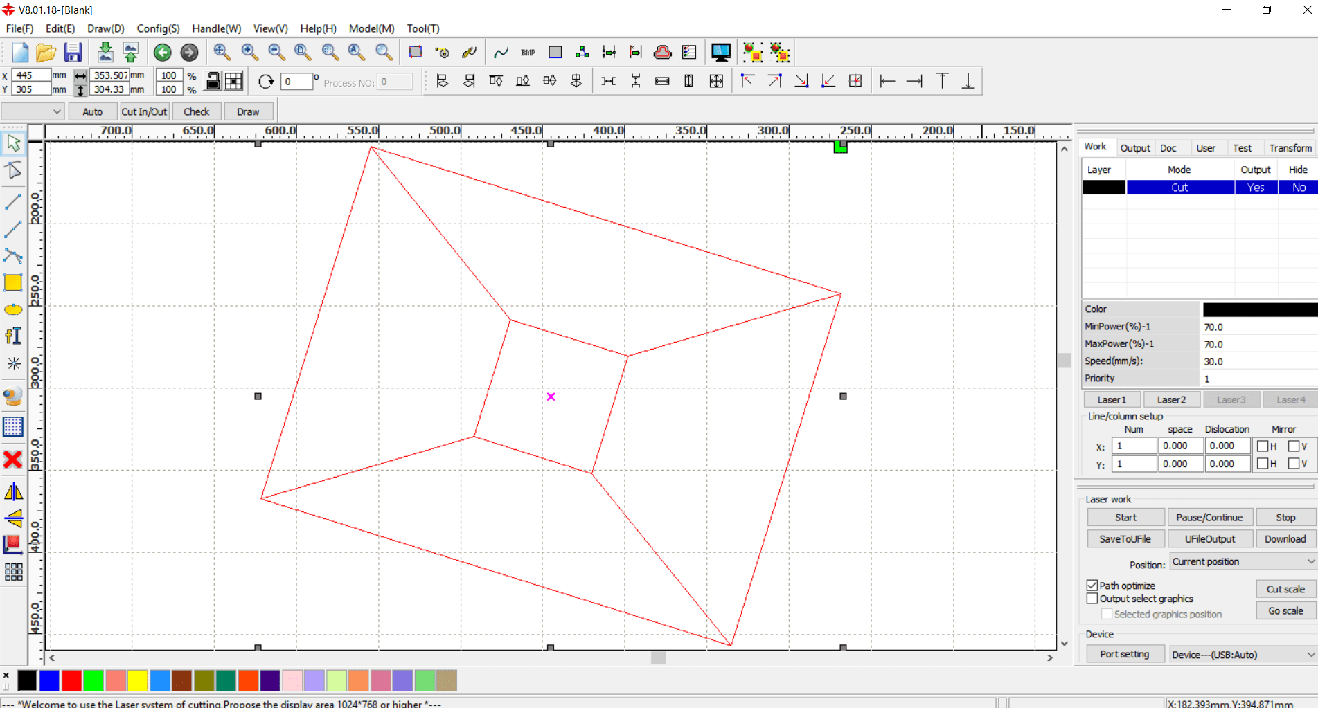
Then open the RDWorksV8 software>file menu>import>select the exported file of FreeCAD>it will get open here
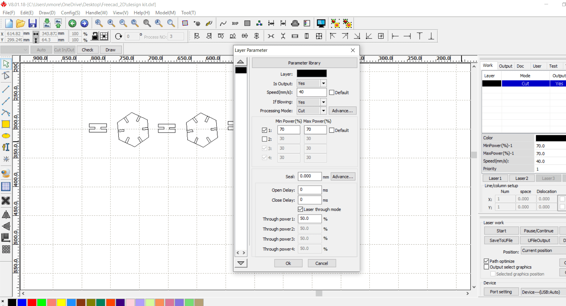
Right side>mode>cut>select the speed and power >here i choose Speed:40 mm/sec and Power:70% of Max. Power
Then arrange the images on worksheet so that will be minimum wastage on material
Cutting and Assemblly
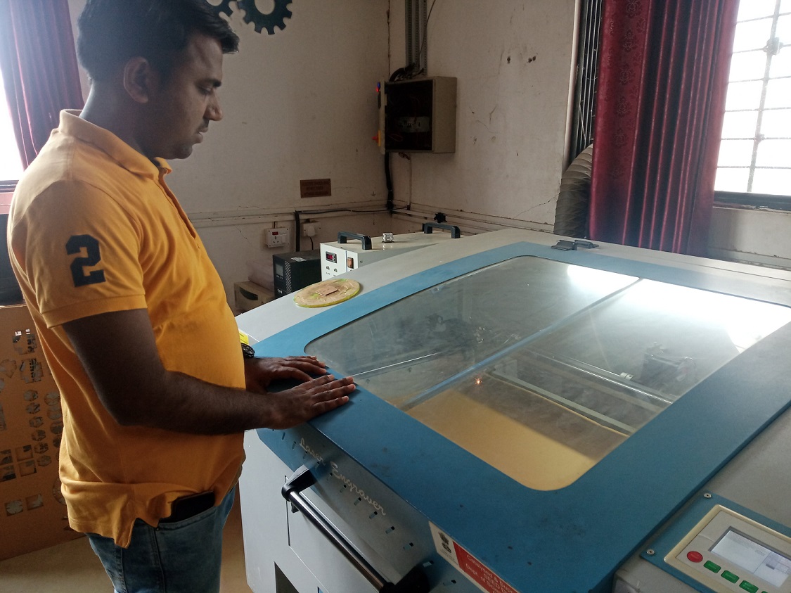
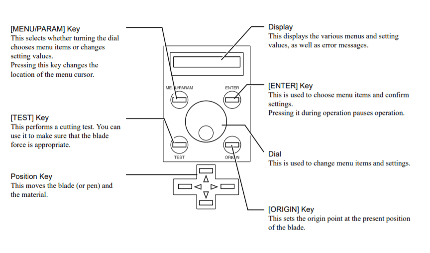
Now start the Laser Cutting Machine by following this steps
Mains(Power Supply)→Isolation transformer→UPS→Air compresser→cooler→mains(laser)→Laser on→Exhaust on→Lamp→redbeam on→Interface
with computer→download the file→start →
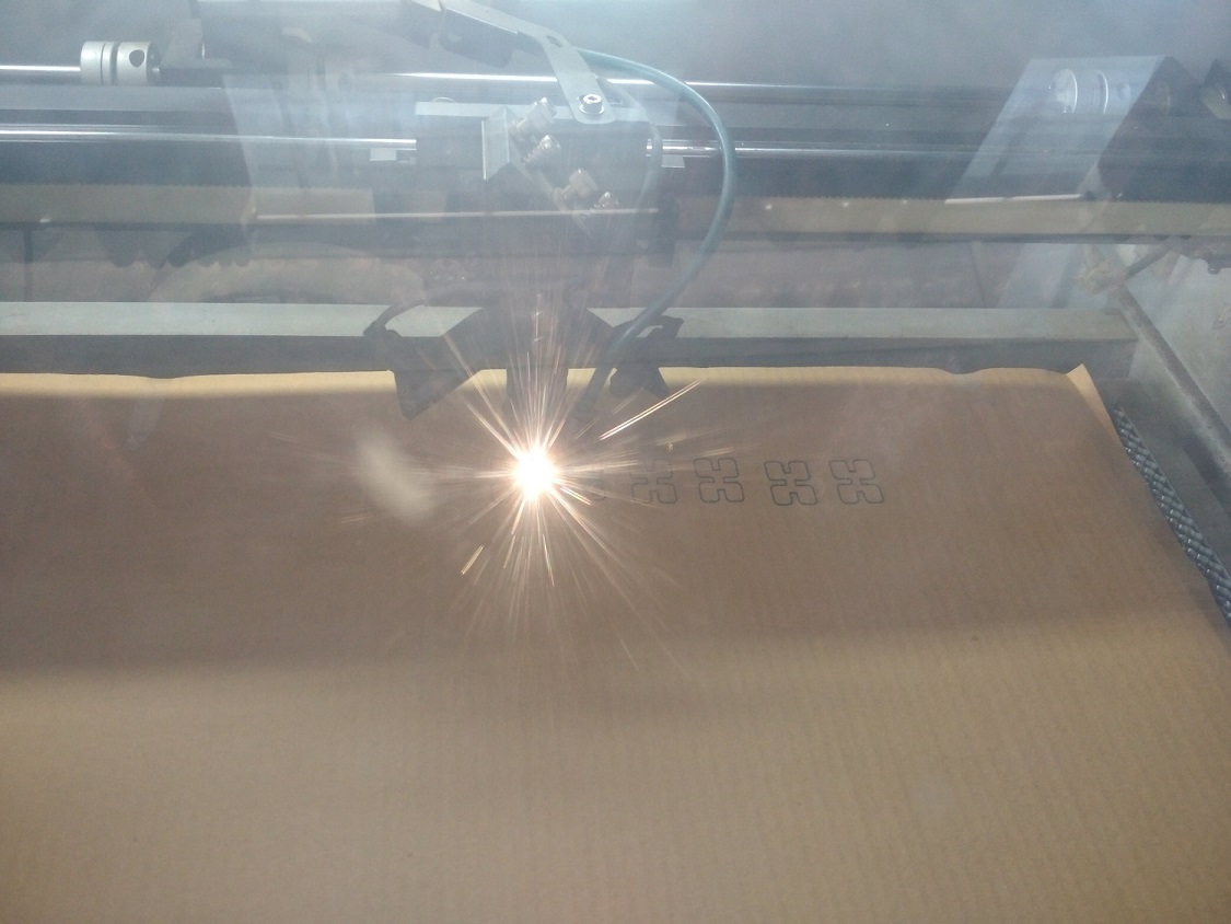
Set the X,Y & Z direction of Laser Beam>after setting press Origin>select the file, in File menu, press Enter> press Frame, just the check the cutting area (if the cutting outside the material adjust it, again press origin)> press Start/Pause button> cutting will get start.

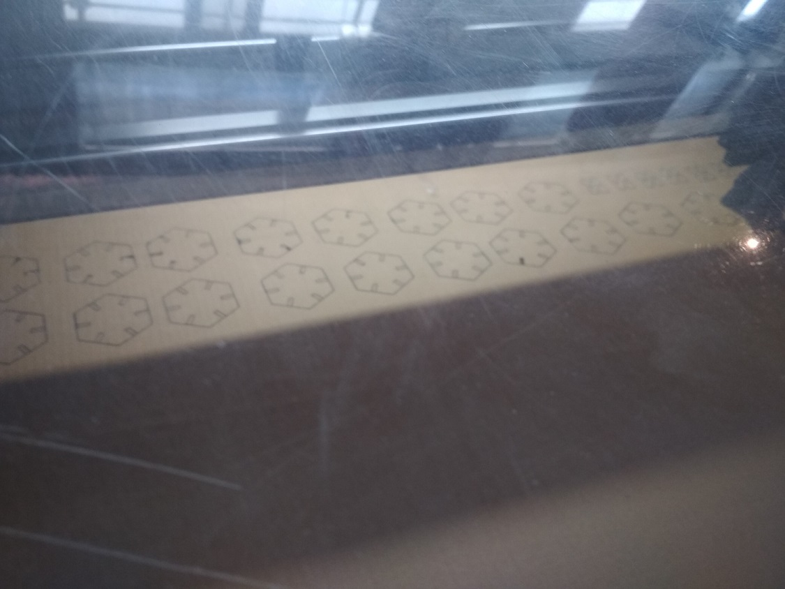
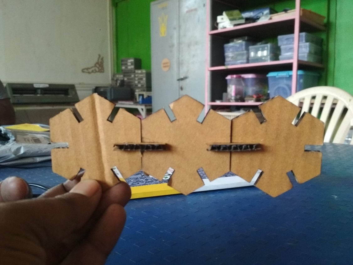
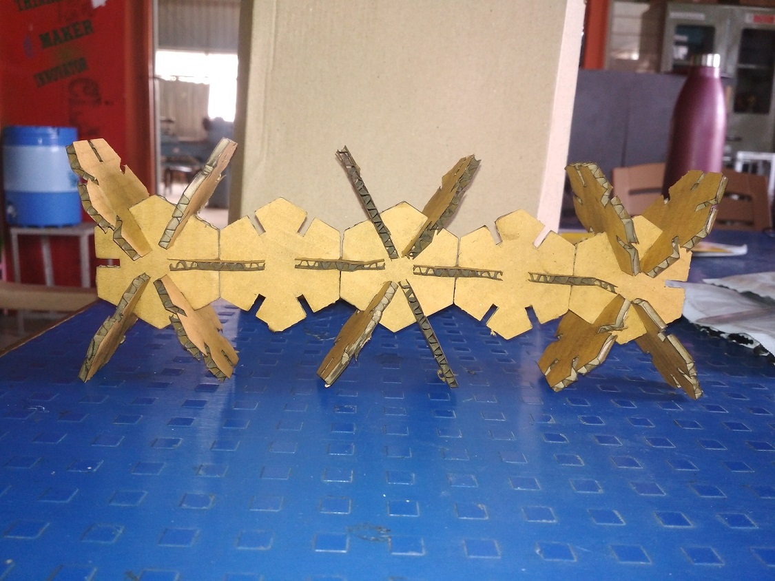
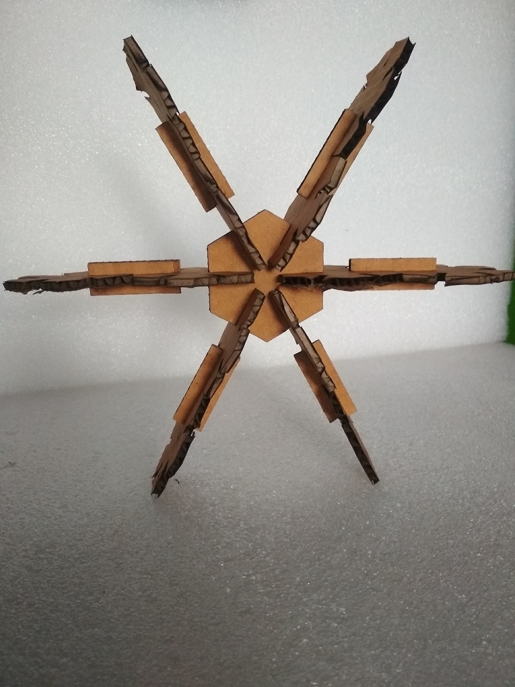
After cutting the object, i tried to assembled the object in different ways
ohh its nice!
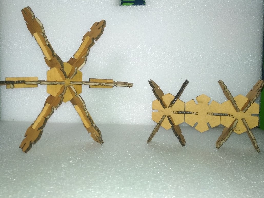
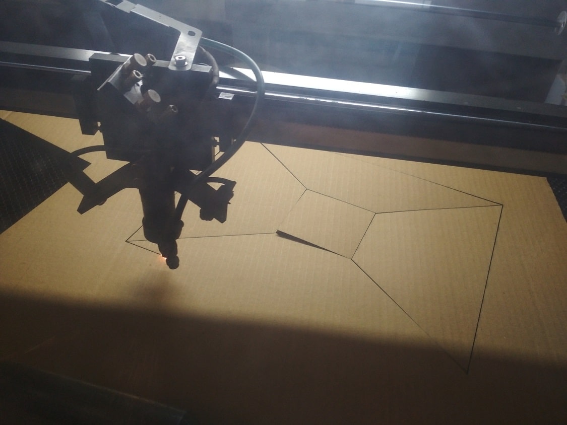
Now i am trying to cut the following prototype object from project i.e. Hooper of chimeny on Laser cutter by using cardboard matrial. Actually i have to cut GI sheet on plasma cutter. so i am trying its prototype here
Now the image is imported in Laser Machine Software i.e. RDWorksV8,Now the cutting is start
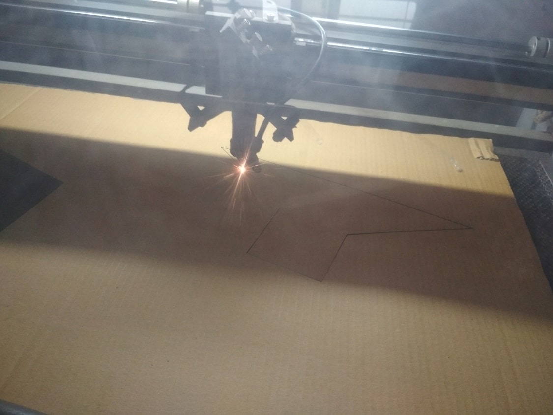
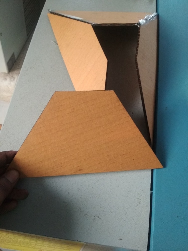
After cutting, I am trying to maake the hooper, but it is not possible, the area for last plane is very less, so there is error in design, now i have to try another method of design I eneginnering i learn about development of plane, i think that i have to try
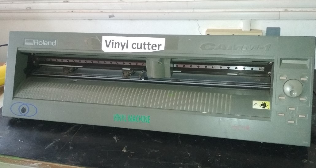
Vinyl Cutting
A vinyl cutter is a type of computer-controlled cutting machine.
Small vinyl cutters look like a desktop printer. Like a printer controls a nozzle, the computer controls the movement of a sharp blade over the surface of the material.
This blade is used to cut out shapes and letters from sheets of thin self-adhesive plastic (vinyl).
The vinyl can then be stuck to a variety of surfaces depending on the adhesive and type of material.
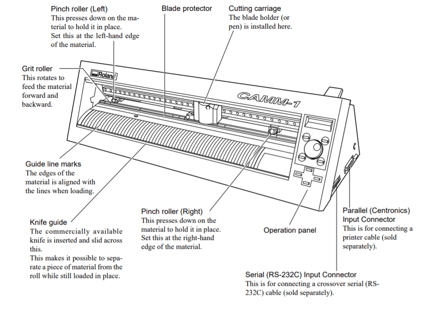
The Vinyl cutter availble in our Fab Lab have the following specification
Driving Method: Media-movement method Stepping motor (Micro-step)
Maximum cutting area: Width:584 mm Length: 24998 mm
Tools:Cutters: Special cutter for CAMM-1 series, Pens: Water-based fiber-tipped pens
Max. cutting speed: During cutting: 400 mm/sec.
Blade force: 30 to 200 gf
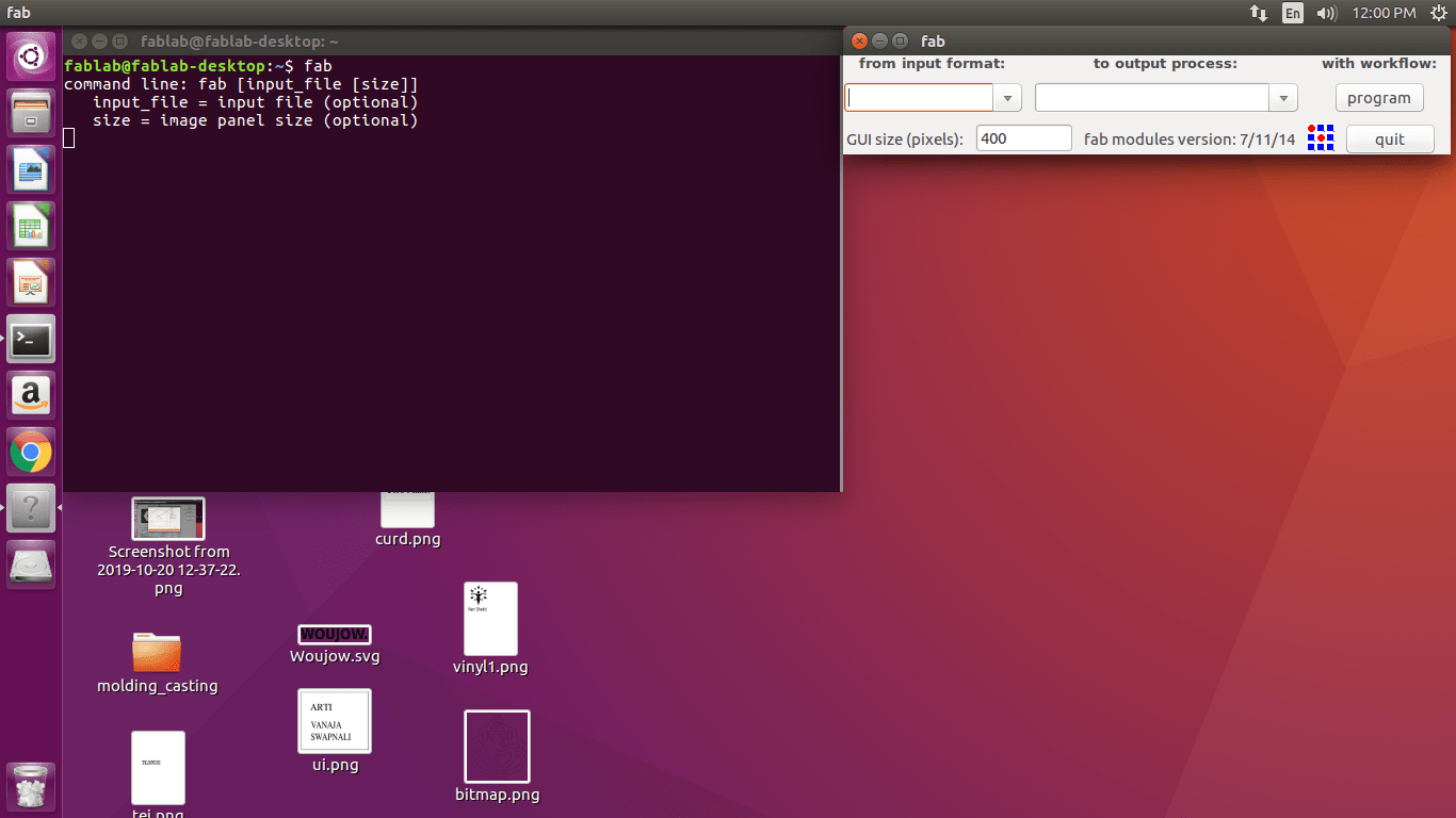
Then open the image in Fab Mode Software for Vinyl Cutter>finally make the path>but the path is not generated for the given image so i have to try another image
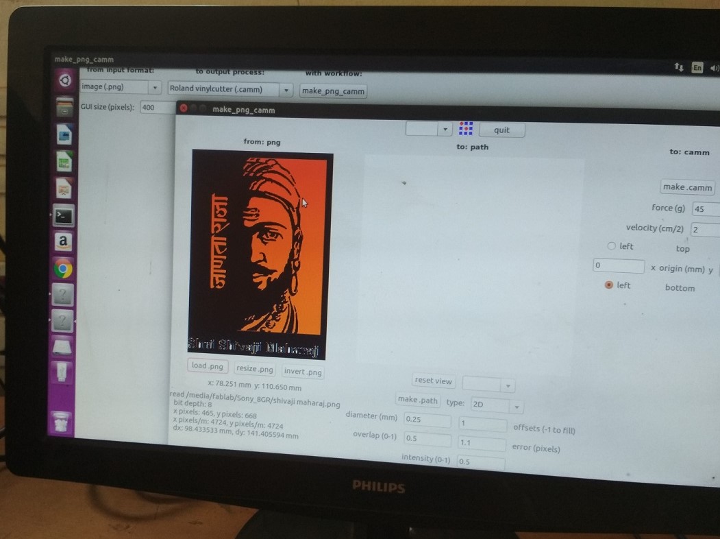
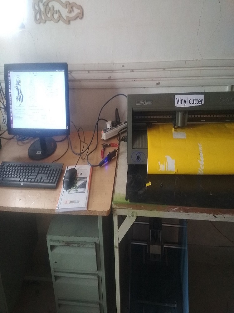
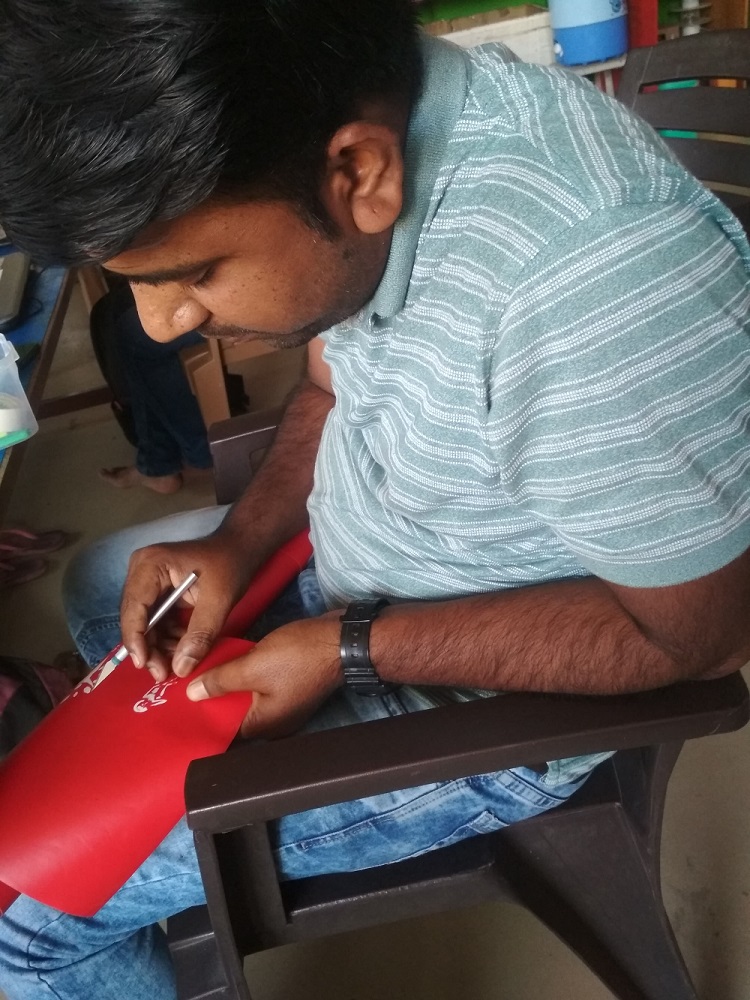
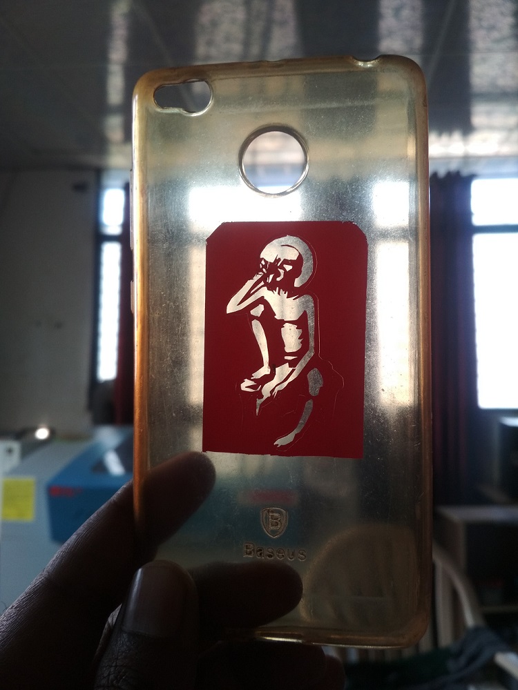
Now the another png is loaded on machine>start cutting>removed unwanted material>final image is pasted on mobile cover
What i learn?
I am learn about
1. Laser cutter's focus, power, speed,rate,kerf and joint clearance.
2. Important of kerf for press fit.
3. Different processes involved in Laser Cutter Machine.
4. Development, evaluation and construction of parametric construction kit.
5. How to use the Fab Mode and other modes for Vinyl Cutter and other machine of Fab Lab.
6. Different process of Vinyl Cutters Machine.
Go to the top
Back
Assignment 5:Electronics Production
The PCB manufacturing process is very important for anyone involved in the electronics industry. Printed circuit boards, PCBs, are very widely used as the basis for electronic circuits.

Fab Academy Course on Digital Fabrication by Nikhilkumar More is licensed under a Creative Commons Attribution-NonCommercial 4.0 International License.
Based on a work at http://fabacademy.org/2020/labs/vigyanashram/students/nikhilkumar-more/.
Permissions beyond the scope of this license may be available at http://fabacademy.org/2020/labs/vigyanashram/students/nikhilkumar-more//contact.html