Objectives of the week
- Send a message between two projects .
- Design, build, and connect wired or wireless node(s) with network or bus addresses.
- Snehal:
- Tejswini:
- Vikram:Asynchronous Serial Communication With AT Commands
1. Group assignment
2. Individual assignment
Task assign to Group members
This week is all about networking and communication.In this week we have to study communication protocol like I2C,RS232 ,SPI .So I ,tejswini and vikram sir decided to study three different protocol.We used three protocols for communication.I have used I2C protocol for communicating between LCD and 328P board.I have used vikram sir's board./p>
I2C protocol:
I2C combines the best features of SPI and UARTs. With I2C, you can connect multiple slaves to a single master (like SPI) and you can have multiple masters controlling single, or multiple slaves. This is really useful when you want to have more than one microcontroller logging data to a single memory card or displaying text to a single LCD. Like UART communication, I2C only uses two wires to transmit data between devices:

SDA (Serial Data) – The line for the master and slave to send and receive data.
SCL (Serial Clock) – The line that carries the clock signal.
With I2C, data is transferred in messages. Messages are broken up into frames of data. Each message has an address frame that contains the binary address of the slave, and one or more data frames that contain the data being transmitted. The message also includes start and stop conditions, read/write bits, and ACK/NACK bits between each data frame:
To check the I2C protocol I have used Vikram Sir board. He used 328p controller IC.On this board I have checked my input and output device. In that I connected ultrasonic sensor as input and LCD as output.I have connected I2C module to LCD.
I have connected I2C module to LCD.SDA and SCL pin of I2C connected to SDA and SCL pin of 328p. Ultrasonic sensor pin trigger and echo connected to PC3 and PC2. After connecting all connections ,I started uploading code to board. For I2C you need to add I2C library in arduino.I have defined echo and trigger pin in code. When I completed all changes I uploaded code to my board and it working as per code.

|

|

This video will explain I2C protocol in detail.I am adding this video for reference.
★ I2C Bus Communications:
-
I2C is a serial protocol for a low-speed 2-wire interface.
-
Develop by Phillips in 1982 for the television manufacturing industry. It was a method to communicate different integrated circuit and television.
-
It is now used by every major semiconductor manufacturer.
-
I2C bus is suitable for use over short devices ~ 1 meter at the speed of 100 Kbaud.
-
The original I2C bus have clock speed of 100 KHz.
-
There is a I2C bus with fast mode up to 400 KHz.
-
There is also a high-speed mode up to 3.4 MHz and Ultra fast mode to 5 MHz.

|

|
To take trial of I2C bus communication between two board, I have connect two arduino with each other in which one acts as master and other act as slave. In which I have connect A4 and A5 pin of one board to another board to set the communication between them. Where A4 is SDA and A5 is SCL pin both pins are require for serial communication between more than one board.
Task3:
For this week group assignments Vikram is going to do communication with Atmega 328p with local webserver.Actually he want to learn this wireless communication for his project work as well.So we assign this task to him as part of group assignments.
Asynchronous Serial Communication With AT Commands
In this tutorial I am going to show you how to set up the ESP-01 Wi-Fi module, how to configure it, and then verify it.In short i want establish communication between the module and another board.
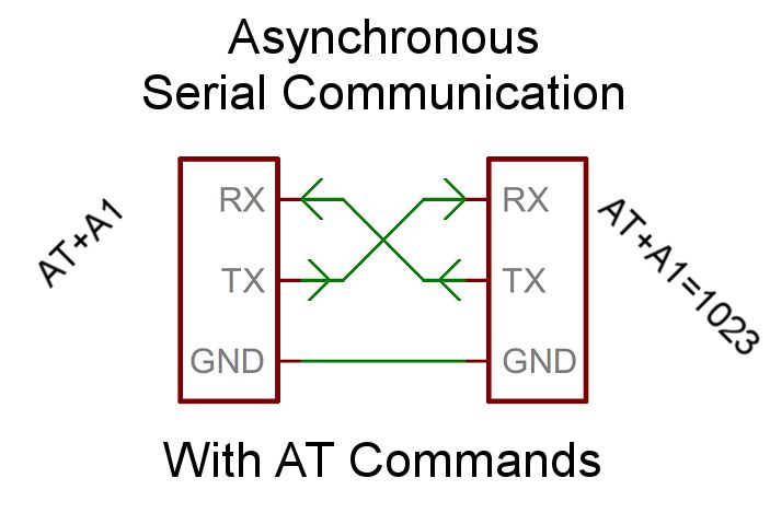
The advantage of Asynchronous Communication is that you don't need the communication being done in sequence, mainly when you define the request code but not the receiving code.Refer from:(https://www.instructables.com/id/Asynchronous-Serial-Communication-With-AT-Commands/)
In the first option, you’re using the Module as an add-on and writing code in the Arduino to talk to it. The other model is that you’re trying to work on the module directly to program it or upgrade it. For our final project here we will have code on the Arduino talking to the module, but to make sure everything is working we’ll be talking to the Module directly (kind of). More on that later.
About ESP 01
he ESP8266 ESP-01 is a Wi-Fi module that allows microcontrollers access to a Wi-Fi network. This module is a self-contained SOC (System On a Chip) that doesn’t necessarily need a microcontroller to manipulate inputs and outputs as you would normally do with an Arduino, for example, because the ESP-01 acts as a small computer. Depending on the version of the ESP8266, it is possible to have up to 9 GPIOs (General Purpose Input Output). Thus, we can give a microcontroller internet access like the Wi-Fi shield does to the Arduino, or we can simply program the ESP8266 to not only have access to a Wi-Fi network, but to act as a microcontroller as well. This makes the ESP8266 very versatile, and it can save you some money and space in your projects. In this tutorial we are going to show you how to set up the ESP-01 Wi-Fi module, configure it, and verify that there is communication established between the module and another device & talked to web server as well.
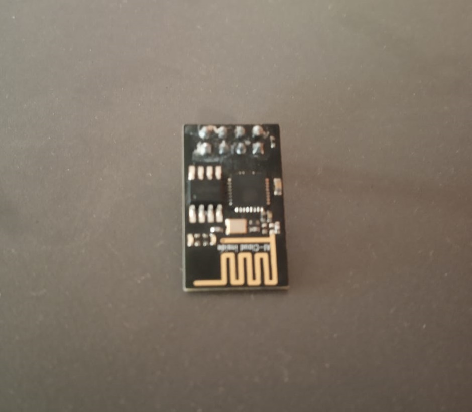
Pin configuration:

Next, we have the Pinout connections. Depending on the article you’re looking at the connections will change. It’s important to understand the pins and how they’re used. In general, you have a VCC for power and your common GND. You also have TX and RX to transmit and Receive. You have two GPIO pins, a reset pin, and a CH_PD pin. This board is designed to be an add-on to another micro-controller and offers a feature for being able to turn it on or off by setting the CH_PD pin from High to Low. In my case, I’m going to leave it on all the time so I’m just pulling high all the time.
CH_PD is a chip controlled power down and needs to pull high in order to run Speaking of voltage, all the articles I’ve seen warnings not to give it too much power, but mine seemed to need more than the 3.5v Arduino served up. In my tests, the module wouldn’t start up correctly with 3.5v which made it very difficult to debug early on. I ended up switching to the 5v pin and everything has been great.
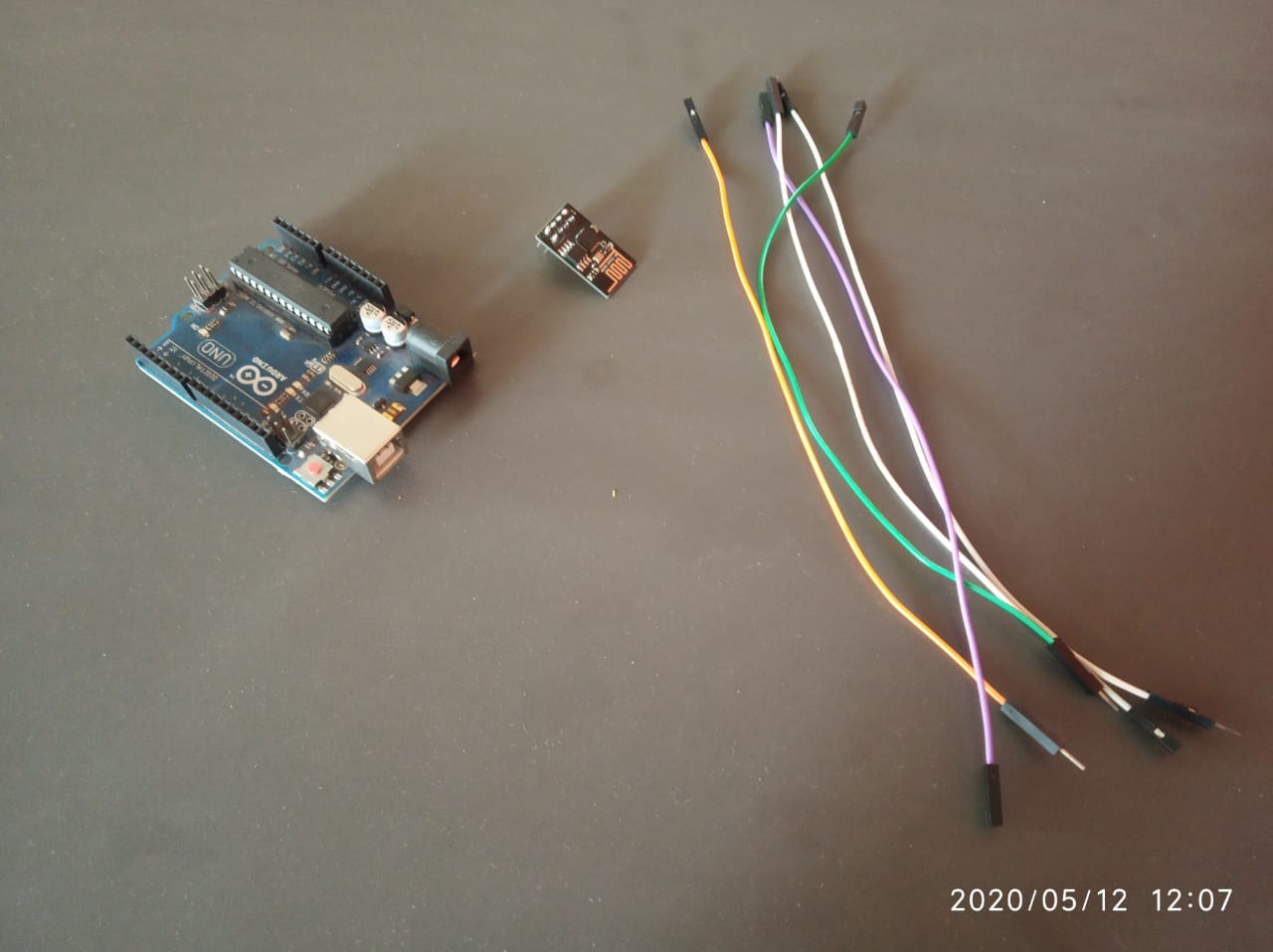
Hardware requirments
Interface Arduino with ESP 01
Arduino -- ESP-01
Note:Use the Uno as a bridge to talk to the module directly. Bypassing the Uno boot loader connecting RESET to GND.
Establish WI-Fi for Arduino through ESP -01
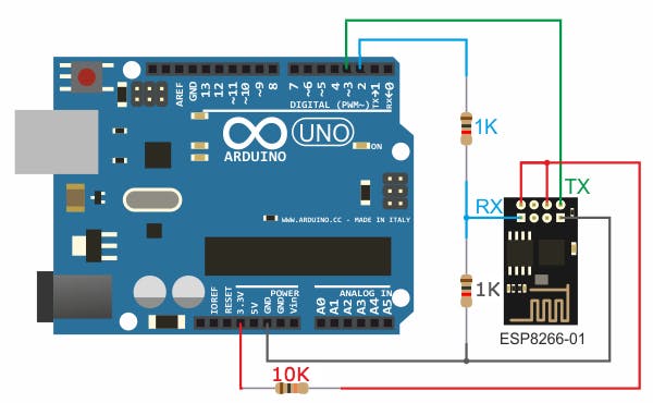
In the circuit there are 2 resistor one of 1k ohm and the other one of 2.2k ohm. The two resistors are used to step down the 5V which comes to arduino into about 3.43V which goes to the ESP-01 board (connected to RX pin of the ESP-01) because the ESP8266EX chip works with 3.3V only and applying a 5V directly may damage it. On the other hand, the TX pin of the ESP-01 is connected directly to the Arduino board without any voltage level converter because here the ESP-01 sends data (at 3.3V) to the Arduino board using this pin.
Note:There is other ways to build a programmer for the ESP-01 module for example by using FT232RL USB to serial converter from FTDI Chip
Run AT commands to establish a wi-fi environment for arduino
open the serial monitor and type the following command: You should get an “OK” response. This means that the module is working and that you are good to go. Now we are ready to test a two way communication between the module and another device.
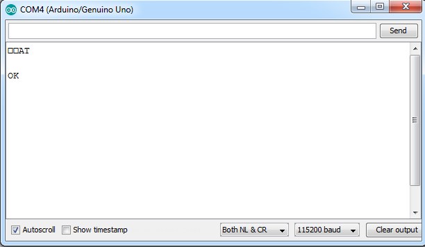
In this tutorial, we are going to set the module to operate in STA mode by typing the following command:
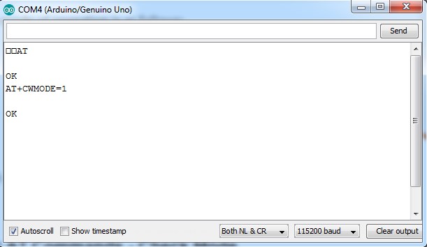
Once we have the ESP-01 operating in STA mode, we need to connect to a Wi-Fi network. First we can check if we are already connected to one by sending the command:
his will display the station IP address of our ESP-01 module.
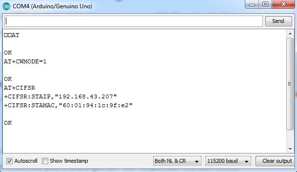
If you don’t get an IP address after entering the previous command, use the following command to connect to your network:
Type the name of your Wi-Fi network and the password to connect to it. Make sure you include the quotation marks. After a couple of seconds, you should get an "OK" response. >
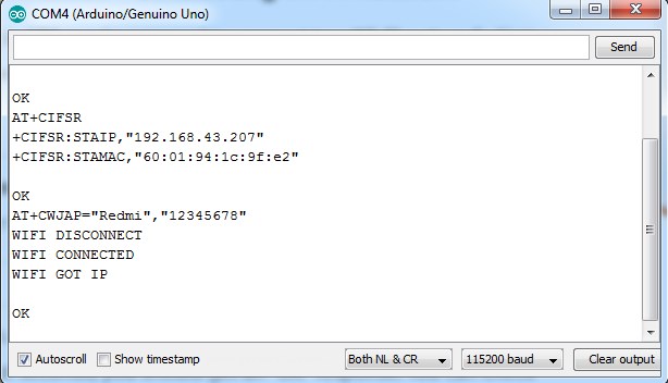
Then we need to enable multiple connections before we can configure the ESP8266 ESP-01 module as a server. Type the next command:
Once again, each number is associated with a type of connection: Single = 0 Multiple = 1
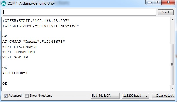
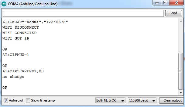
The following step is to start the server at port 80:
The first number is used to indicate whether we want to close server mode (0), or open server mode (1). The second number indicates the port that the client uses to connect to a server. We chose port 80 because this is the default port for HTTP protocol.
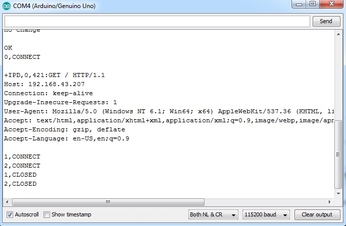
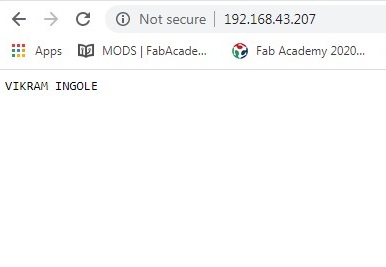
Now, when we open a web browser and type the IP address of our ESP module we get the following response as shown in the image above. This is the HTTP request that our computer sends to the server to fetch a file. It contains some interesting information such as what file you want to retrieve, name of the browser and version, what operating system you are using, what language you prefer to receive the file in, and more.
We can now use the following commands to send some data and display it in our web browser’s window:
The “0” indicates the channel through which the data is going to be transferred; while “15” represents the number of characters that are going to be sent. When we hit enter, the symbol “>” appears. This indicates that we can now type the characters that we want to send to the browser. In this example we chose “VIKRAM INGOLE.”
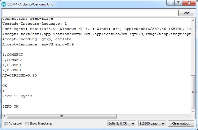
Once we hit enter, our message is displayed on the web browser’s window as shown in the image above.
★ Conclusion::
From this group assignment we have studied different communication protocols like I2C ,SPI.We understood how this protocols works.After finishing group assignment we did individual assignment.