Week 04 : Beginner's Guide to ISP Production
Assignment
Make the FabISP in-circuit programmer.
My Goals
- Make a working Fab ISP as instructed
What I Learned
- How to mill PCB
- How to use Fab Module
- How to change mill bits on the Model MDX20
- How to solder components to a circuit board
- How to test a circuit board with a multi-meter
- How to program an ISP
- How to troubleshoot a board
Tooling, Materials & Speeds
- Modela MDX20
- 1/64" mill bit for traces, 1/32" mill bit for cutting
- PCB
- Fab ISP parts from Fab inventory
Documentation
This week’s assignment was to mill and stuff the Fab ISP. This is an ongoing battle for me because I have no electronic’s experience and pretty much everything that could go wrong has gone wrong, and I have documented this experience with the purpose of helping future newbies like me.
First, I read the tutorial on Fab ISP production Fab ISP Production
STEP 1: Mill the Board
This part is easy. The traces and the interior files have already been created for us. Just follow the steps below.
Milling Fab ISP traces and interior on the Modela MDX-20
- 1. Tape the PCB with double-sided tape
- 2. Press down firmly on the sacrificial layer
- 3. Load Top File and Cut file to the computer
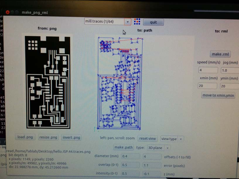
- 4. Open Fab module (type “fab”)
- 5. Set input to "Image.PNG"
- 6. Select appropriate machine (Modela MDX-20)
- 7. Load the PNG file of the traces or interior you want to mill
- 8. Set mill traces (choose 1/64 to engrave or 1/32 to cut)
- 9. Click “Make path"
- 10. Set starting point (example: 12mm x 12mm to start - each square is 5mm)
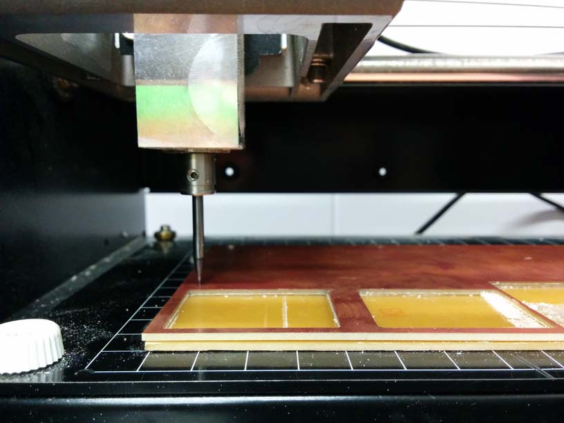
- 11. Add appropriate drill bit, as high as it will go on the machine arm (1/32 for cutting, 1/64 for engraving)
- 12. Lower the machine arm using the “Down” button on the Modela - leave a depth that is similar to the thickness of the PCB
- 13. Lower the drill bit down to sit comfortably against the PCB, tighten by holding the bit with fingers to keep it from sliding upwards
- 14. Start trace
- 15. Repeat steps 5-13 for the interior
What to do if...
- Traces are unevenly engraved
- When engraving traces, you might notice that the engraving may not be even across the whole board. Usually, half the trace looks ok with lots of burr, while the other half the drill seems to have barely touched the PCB.
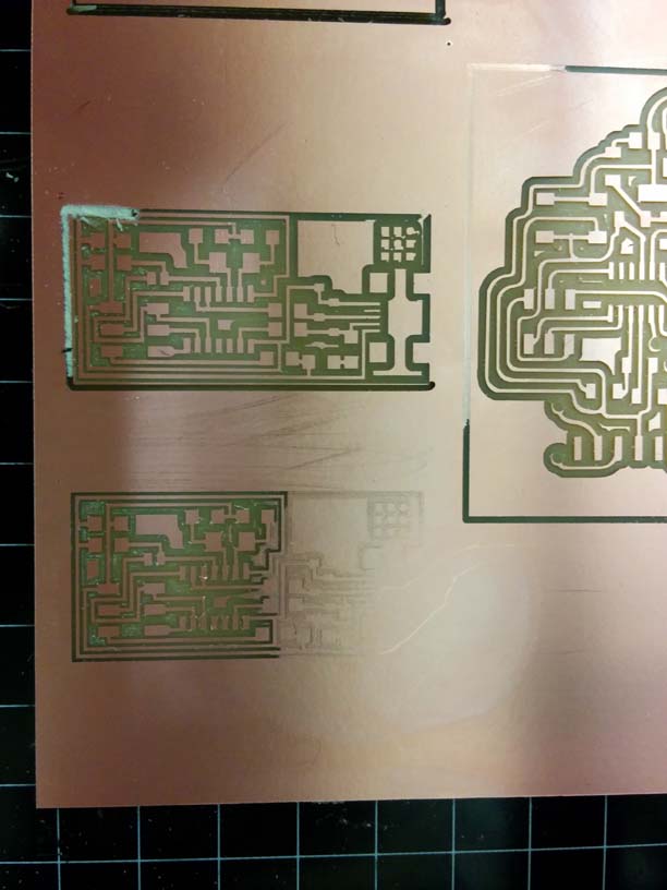
- Press the board down harder
You can do this by using your hands or even a harder object like the plastic part of car keys. You want to flatten the tape under the PCB.
- Check the drill bit to make sure it’s touching the board.
You can do this by slipping a piece of paper under the bit and if it slides under, that means it’s not tight enough against the board.
- If the drill bit appears to be tight against the board, try moving the drill bit to the side of the part of the board where this is happening, and re-trace using the same origin point.
You can do this by re-setting the X and Y axis values to a location that’s on part the part of the board that isn’t engraving properly. The drill bit should move to that location and you can test with a piece of paper again. This is usually the problem when I encounter this problem.
Simply re-set the Z axis (the drill bit) based on this location. This means the Modela will engrave a bit deeper on one half of the board, but this is acceptable.
- Then return the drill to the same origin point, and simply re-trace.
You may have to cancel your last tracing job first, which you can do in the Fab Modules - the instructions should be next to your machine.
- PCB disconnects with the sacrificial layer in mid-trace
- If you’re not watching the machine, the sound of this happening should alert you that this is happening because the sound is unpleasant (as in more unpleasant than the sound of the Modela cutting PCB properly).
- Check the tape
This should be the first step before you start cutting. Most of the time, you’ll be cutting on a board that is already mounted on the sacrificial layer, and it’s not safe to assume that the person who was cutting before you taped the board down correctly.
Sometimes, other people tape only the part of the board they want to cut. Or they tape really sloppily (uneven distribution, overlapping edges, missed spots). It’s safer to really check the board before you even start, and re-tape if the taping doesn’t meet your standards. Otherwise, you end up with a botched trace and waste time and material.
- Re-tape and try again
Because you will have taken the board off the sacrificial layer to re-tape, you’ll likely not be able to re-trace. Pick a new origin point on the board, minimizing the amount of wasted space.
STEP 2: Stuff the Board
I like to start with setting up a nice work station, which includes:
- Turn on the extractor
- Turn on the light
- Turn on the solder - make sure the appropriate soldering tip is attached
- Find the solder wire
- Find the copper wire
- Get the wire clippers - you’ll want this handy to cut more solder or copper braid as you go
- Get the monocle - you’ll want this handy to check your soldering job as you go
- Get the hot air gun - you’ll want this handy to remove parts as you go
- Set-up your laptop next to the soldering station - you’ll want Neil's Diagram
- Set-up your components on a labeled piece of paper next to the soldering station
Soldering Best Practices:
- 1. Start with the mini USB
This is one of the hardest pieces to solder, except for the ATTINY, so you want to start with it first in case you screw it up. One of the easiest way to screw up the USB is to put too much solder in the four little feet. Neil tells us we can just glob on the solder and remove excess with the copper braid, but I had no such luck with the copper braid. I soldered each little foot individually.
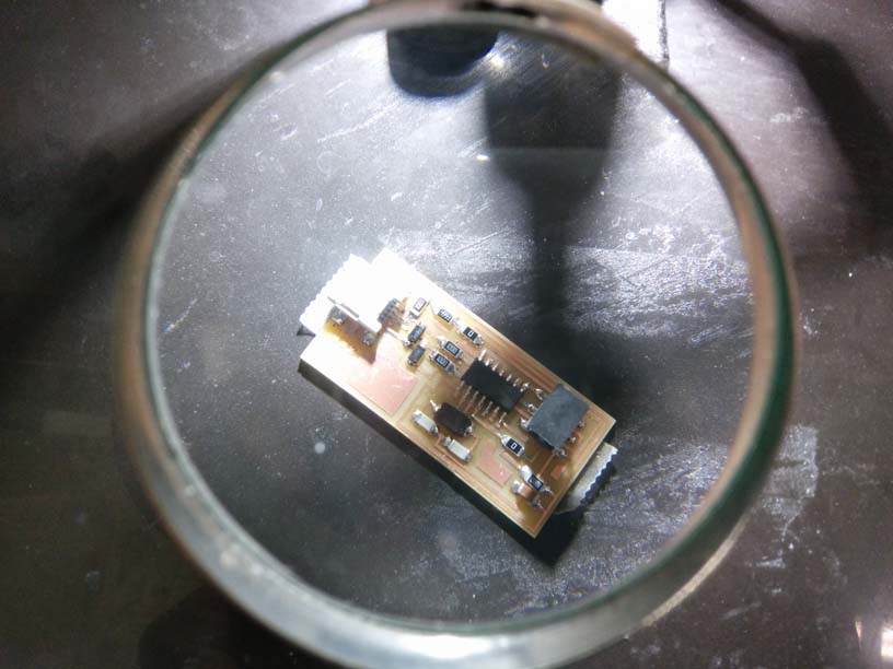
- 2. Start from the middle and work your way out
It’s really easy to get confused between the different resistors, so it’s a good idea to keep all your components on a piece of paper next to you with their labels clearly written. Most of the components were easy to solder. I had the most trouble with Crystal and the Diodes because they’re quite tall and I couldn’t get the solder to stick to the sides of them as shown in Anna’s tutorial.
- 3. Solder the ATTINY last(ish)
This is the most delicate component on the board and it does not like being heated. I did it last, but found it really challenging soldering the little feet next to the Crystal. Because my first Fab ISP didn’t work (more on that next), I will solder the Crystal and 2 Capacitors after the ATTINY next time.
STEP 3: Test the Board
Before programming the board, Craig suggested that we add an interim step to test the circuits on the board before programming. This way, we can fix any errors on the board rather than detecting them in the programming process.
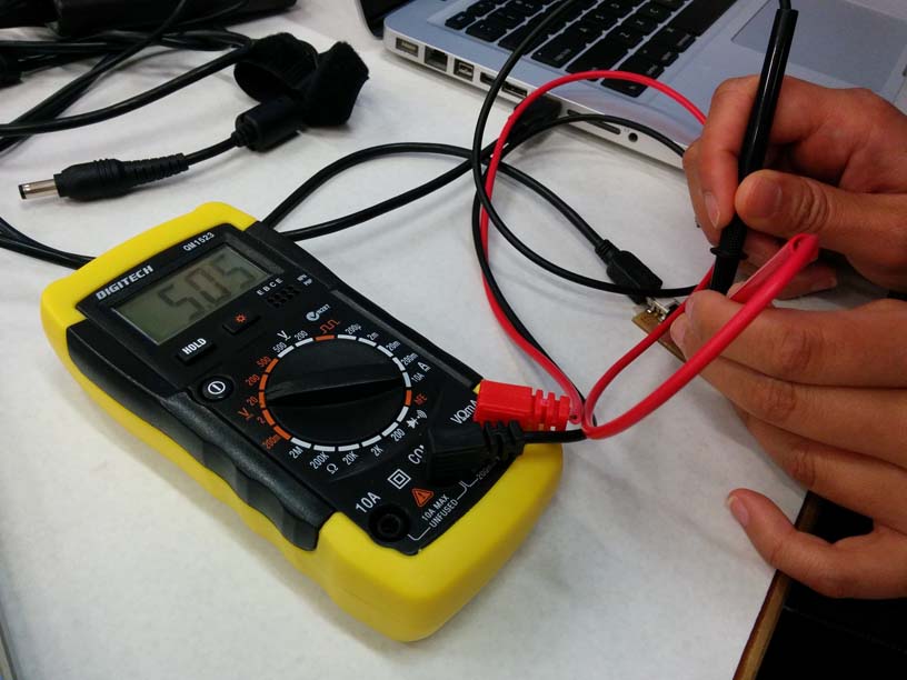
IPS Testing with Multi-Meter:
- Set the multi-meter to 20V (because the ISP is 5V)
- Use Black for ground and Red for VCC
- Using Neil’s diagram of the Fab ISP, see if there is a 5V current running from GND to VCC on key components
- Check the USB - if there’s no current, there’s a short - check the little legs (they should not be connected to each other)
- Check the ATTINY - if less than 5V, check the little legs and if they are connecting properly to GND and VCC
- Check the ISP - if less than 5V, check each of the 6 legs and if they are connecting properly to GND and VCC
- Use the Beep test on the Multi-Meter to make sure that the connections that should be connected are connected, and those that are not supposed to be connected are not connected
- If it’s not the resistors, if it’s not the power, then it’s the resonator (clock)
My results:
USB = 5.05V
ATTINY = 5.05V
6-pin = 5.05V
SUCCESS! Or so I thought… more on this later.
STEP 4: Program the Board
Next, I followed the tutorial on Fab ISP Programming.
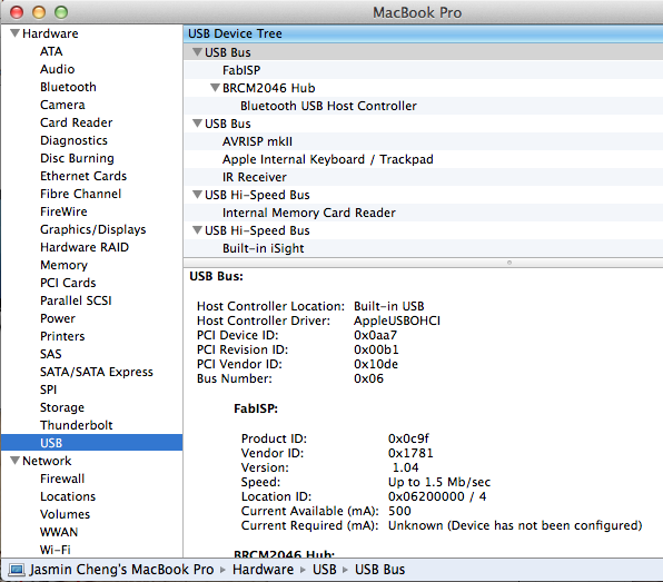
I’m using a Macbook Pro 10.9.5, and here’s a handy list of everything I installed:
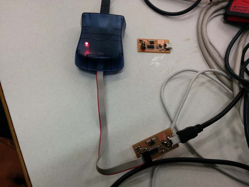
I connected my ISP with Anna's ISP, making sure that our boards were connected in the same direction.
I was able to make clean and make hex just fine. When I used the command “sudo make fuse”, I got there error:
dynip-54-242:fabISP_mac.0.8.2_firmware jasmincheng$ make fuse
avrdude -c avrisp2 -P usb -p attiny44 -U hfuse:w:0xDF:m -U lfuse:w:0xFF:m
avrdude: usbdev_open(): did not find any USB device "usb"
make: *** [fuse] Error 1
Here’s what I did to troubleshoot:
- 1. Checked to make sure the second ISP was connected to power (I totally forgot)
- 2. Checked to make sure Terminal was in the right folder
- 3. Edited the Makefile once more, and deleted the # in front of the avrisp2 code
- 4. Tried a different ISP
- 5. Tried plugging the IPS’s in differently
- 6. Used Craig's AVRISP MKII - saw an angry flashing light which means my ISP doesn’t work
- 7. Re-double-checked the currents on my ISP
At the regional review, Francisco recommended that I replace the ATTINY on the board, as that is the most likely reason why it's not working. I did that. I re-flowed all the connections. I re-tested. I tried to program it. It just wasn't working.
At the end of the day, I decided to make a new board. It only took about 20 minutes to cut the HelloISP board again. It pays to take good notes. Gatherine the components and soldering took less than an hour. I connected the new ISP to the AVRISP and got a green light. So far so good. Then I tried to program it, and got the same error as before when I tried to make fuse.
avrdude -c usbtiny -p attiny44 -U hfuse:w:0xDF:m -U lfuse:w:0xFF:m
avrdude: Error: Could not find USBtiny device (0x1781/0xc9f)
avrdude done. Thank you.
Craig came to my rescue once again and reminded me to update the Makefile in the fabISP_mac.0.8.2.firmware folder on my desktop. I deleted the # in front of the avrpisp2 code and added # in front of the usbtiny code. This time, it worked.
I wasn't confident that I was going to be able to complete this assignment. I've gone over the steps so many times in my head trying to figure out what went wrong the first time. Even though I spent a lot more time on this than anyone should, I learned a lot about troubleshooting and got extra soldering practice. The important thing is that it works.
Helpful resources:
