The Holdable Heart
The experience of holding your heart in the palm of your hands.


Downloads
Final design files and code for Holdable Heart
Concept Statement
To see a world in a grain of sand
and heaven in a wild flower,
hold infinity in the palm of your hand
and eternity in an hour
- William Blake
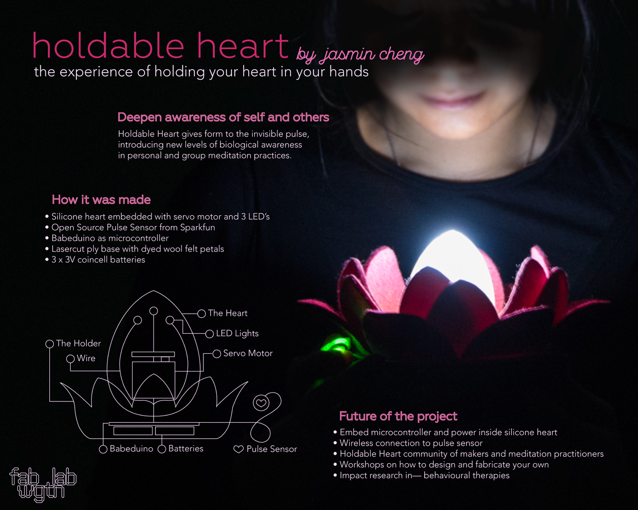
The concept of the Holdable Heart is to make the beating of the heart, an unseeable and private internal experience, and make it an experience that we can see, touch and share with others.
- pulse sensor that sends a signal
- Servo motor arm rotates in each direction for diastole and systole
- LED lights lights for diastole and fades with systole
Design Research
Life moves too quickly and the world is yearning for a deeper connection. Whether we do it through dance or yoga or exercise or meditation, these practices shut off our busy thinking minds and allow us to be fully present in this world.
Pulse activated objects are nothing new. People have made tshirts with LED lights that blink with every heartbeat, and beating hearts in a jar. These two examples were heavily referenced in the development of my own project, but I wanted to take the tactile experience of the object further, making the heartbeat something you can see and feel.
I have been meditating and practicing yoga on and off for several years, and always found these practices to be the most unifying of experiences. I wanted to create an object that could be held in meditation, or to sit amongst the candles in a yoga studio.


I was also interested in setting it on a work surface or office desk. These are often the moments when we become most disconnected with our bodies. It happens so often - we forget to eat, to sleep, to stretch, to breathe, to pee. I wanted the Holdable Heart to actively engage our awareness as we work, as a gentle but consistent reminder that we are more than our ego’s at work.

The lotus flower is a timeless zen symbol, but I was also inspired by the protea magnifica, a South African plant that is sold at the Sunday market in Wellington Harbour. Anna bought me a pink one one weekend, and we talked about how its colour and petal arrangement could be incorporated into my designs.

Heart Design
To start my design, I had to know what constraints I'm working with. The main constraint would be the servo motor because I wanted to use the smallest one (the most holdable), but because it's not very powerful, I wouldn't want to embed it in too thick of a silicone object, otherwise you wouldn't be able to feel the heartbeat.
Starting from there, I designed the object's dimensions around the servo motor.


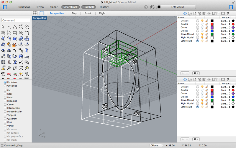
For this, I used Rhino, which I learned how to use in Week 05. Since I knew how big the Servo motor was, I used that as the limiting factor of my design. I wanted to be careful not to embed the motor too deep in the silicone to ensure that the motor movement could be felt by the person holding the object.
After consulting with Wendy several times on the mould design, we decided on a 3 part mould. There would be 2 parts forming the shape of the object, and the third would be a plug at the top that would allow me to hot-glue a servo motor to the end of it to be embedded within the Silicone. We would hand-drill 3 x 6 mm holes into the plug so that we would be able to feed 3 x 5 mm LED’s on wires into the silicone mould.
Before casting the mould, I wanted to make sure that the wire for the LED's would not react with the vario, so I borrowed Anna's tube moulds and made a test. The vario cured normally within a 12 hour period.

I also wanted to test to make sure the servo motor being cast in the vario would not react. Again, the silicone cured normally.

I milled out the mould in wax on the MDX 40, which took about 23 hours in total. Right before I was about to mill, Ben reminded me to add a 0.2 offset in the locator wedges so that they would slot together. I quickly updated the mould design to include the offset. Unfortunately, I had already milled out the servo plug mould, so Wendy helped me manually chisel off the offset. She showed me how to manually add pour and air holes using a hand drill. We decided to use a 6 mm bit for the 2 air holes and 9 mm bit for the 2 pour holes. Finally, we used a 12 mm bit to create sprues for the pour holes to make it easier for the silicone to flow through without getting caught in in the mould. I used steel wool to smooth out the interior, which were a bit burr-y.


I used solid core wire to wire up the LED's. My plan was to cast the LED's in the silicone mould, so I had to leave enough wire outside of the mould.

I hot glued the dummy servo motor to the end of the plug. I also hot glued 2 small pieces of plastic to the sides of the servo, to give the servo more room to vibrate. I threaded the LED's through 2 air holes and 1 pour hole. The 4th pour hole would be for the servo wires. Once I was happy with the LED placements, I hot glued the wires to mould so they would stay in place during the pour, making sure not to plug any of the air or pour holes.

To calculate the amount of vario to mix up, I used an online weight to volume converter. The volume of my egg/avocado mould (144.38 cm^3), minus the approx volume of the plug and servo (2.76 cm^3 + 7.45 cm^3) was 134.17 cm^3. Based on the density of Vario15 (1.06 g/cm^3), I'll need 142.22 g.
I thought it would take maybe 30 minutes to pour. To increase the viscocity and to minimize bubbles, we warmed the vario in a hot water bath first, and added 10 g of dilutant.

Once Wendy and I started pouring, much to our surprise, it ended up taking 2 hours, which is about 1 g per minute. Luckily, vario15 has a 2 hour pot life. Next time, I'm making a funnel.
I waited overnight for the silicone to cure. Wendy helped me with the demoulding. We wanted to demould in stages since the surfaces were likely to still be a bit sticky.
First, we took off the clamps and inserted a thin ruler between the two sides of the mould to start introducing some air into the mould. We very slowly started to wedge more and more space into the mould, until finally we were able to gently pull one half off the mould off.

Despite the careful pouring, there were two big bubbles at the bottom end of the mould. I believe this was because of some burrs left over from the Modela, which I hadn't completely smoothed out using steel wool. I could definitely feel the unevenness in the mould after the fact.

The one side of the mould was definitely a bit sticky, so we put it into the uPrint (which had been on) to finish the cure for another hour.

When I finally finished demoulding, I then removed the dummy servo and inserted a working servo. I had to use the Japanese saw to remove the ridges on the side of the servo, and used sand paper to smooth it out. It's really important to be careful not to accidently damage the servo wires with the saw or sand paper.
Holder Design
I probably spent a disproportionate amount of time designing the Holder. The main problem I had was in deciding what material to make it.
The purpose of the Holder was to be a base for the Heart to sit on when it's not being used. It would also house all the electronics (the Babeduino, the batteries), and all the wire that would connect the heart to the Babeduino and batteries.
At first, I thought I would make it with composites. I did extensive mould design and material testing in Week 13: Composites. I knew from my design research that I wanted to create some kind of cross-breed of a lotus and the protea magnifica, but couldn't wrap my head around how to do it.
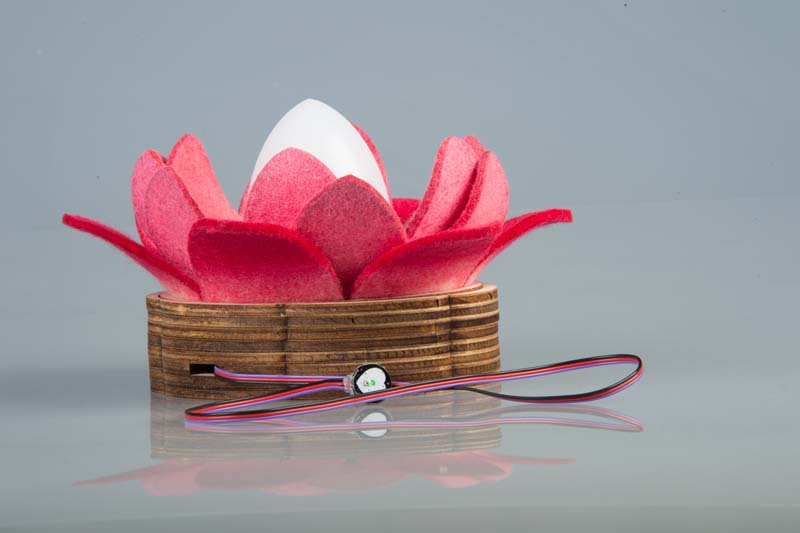
Finally, I decided to use laser cutting to create the base. I felt like it would allow me to work out the dimensions of the base using ply, which would be more cost effective and easier to modify than composites, which required a real commitment of time and resources, and isn't easily changable.

This ended up being the best decision I made because once I started researching laser cut lotus on Pinterest, I discovered the idea to use wool felt. I made a small test and dyed it, and discovered in the process that wet felt was highly mouldable, and was able to quickly whip out a new holder design that was almost exactly what I'd always imagined.


Electronics Design
The Holdable Heart is very simple in terms of electronics. The heart sensor sends a signal to a microcontroller that tells 3 LED's and a small servo motor to move in tandem.
The biggest decision I had to make was whether to use an ATtiny or ATmega. The benefits of using an ATTiny would be:
- Easier to mill, solder, test
- More cost effective
The downsides of an ATtiny would be:
- Servo Library for Arduino IDE runs at 16 mHz
This means, I would have more complications in programming in order to get the pulse sensor to talk to the Servo motor. A previous Fab Academy student, Neta Amir has solved this problem before and found the SoftwareServo Library which allows the servo to run at 8mHz. He says it's "more jumpy than with the ATMega".
I finally decided to build a Fabduino, which would be more difficult to mill, solder and test, but if I knew that if I could get it to work, it would make programming much more simple as I have working code for the pulse sensor and servo motor that runs at 16mHz.
The Babeduino
We call it the “Babeduino” because it’s a babe - beautiful to look at, and user friendly. This ended up being a collaborative project between Anna, Ben, Geoff and I. Anna took the lead on designing the board, while Ben provided a lot of useful improvements based on his extensive experience working wiht the ATMega.
We wanted the Babeduino to be similar to the Arduino Uno with a 20mHz resonator which would allow us to use it to control servo motors. We started by studying the Fabio and the Fabkit and made a list of components that we’d like to have:
- ATMega 328P
- 20 mHz Resonator
- Both regulated and unregulated VCC in's (including FTDI in)
- Switch between regulated and unregulated power
- 6 pin header for programming
- LED to show power
- 17 I/O's (4 GND / 4 VCC outs)
- RST Button
The Babeduino ended up becoming a huge success - we have 4 working ones at the lab now. More working Fabduinos than FabISP's! YEAH! You can read more about the Babeduino here.
More on Electronics
Once I had decided to use the Babeduino, I needed to decide whether to lay my LED's out in paralell or in series, which affects how the current is distributed across the 3 LED's. Craig jumped in and recommended a new tool for us to try called LED wizard which basically recommends the best layout based on the amount of power you have and the number of LED's you're using. The tool recommended that I connect my LED's in parallel which would allow the LED's to share a single power supply, which makes it more energy efficient.

I designed a little breakout board for the LED's with 3 VCCin's and 1 common GND.
I had to make a similar decision with the batteries. Craig suggested that I read up on how to Wire Batteries on Instructables, which told me that I needed to connect my batteries in series because I wanted to double the voltage at the same capacity.
I had originally thought that I would need 2 x coin cell batteries 3V each, but Ben told me to consider the dropout voltage was 1.1V on the Babeduino Regulator LM3480 Datasheet
I ended up designing 2 breakout boards:
- LED's in parallel, which would have 3 VCC-in's, and a common GND
- 3 coin cell batteries in series with 1 VCC out and 1 GND.


Pulse Sensor Design
I started designing a pulse sensor in Week 10 Input Devices and have continued developing it for my final project. After using it to complete the Week 15 Interfaces assignment, I realized I needed to greatly improve the digital signal of the sensor in order to use it for my final project.
Daniel introduced me to Bret Downing at Fab Lab Perth, who has had experience in designing pulse sensors in the past. Bret was so kind to review my schematics and documentation and gave me some deeper insight into how this pulse sensor works.

The dual op amp basically magnifies the signal by 100 x at the first op amp, and again 100 x through the second op amp. We checked the op amp data sheet and he showed me that the op amp does not read values below 0V, which means the bottom of the signal is chopped off. Bret told me that this is a good thing because we only want to amplify the peaks of the pulse.
Another thing he clarified for me was that the 2 diodes are not for reverse polarity protection; they are actually to amplify both signals so that both diastolic and systolic peaks can be read (so we would see 2 peaks).
His advice to me was to bring the signal above ground so that the peaks of the pulse signal could be read by the op amp.


He provided me with a list of checkpoints and expected values to test on the new board with the oscilloscope:
- Diodes - 1-1.5V from GND (not too much ripple)
- Phototransistor Output - 1-4V (tiny millivolt ripple)
- Both Op Amp Outputs - 1-5V (tiny millivolt ripple)
- Signal Output - 1-2V
He also provided me with some considerations:
- The second opamp should show a bigger ripple than the first
- If the Phototransistor output is not between 1-4V, just adjust the value of the resistor.
- If the signal is getting visibly chopped off at the top or the bottom, adjust using the potentiometer

I produced a new board and proceeded to test it based on Bret's suggestions.

I was able to see a wave signal on all outputs except for the Diode-to-GND line. The best thing was I saw a signal of up to 1.2V on the Signal output, which was pretty much what Brett predicted. You can see the results of the test here:
I wanted to see if I would be able to use this sensor to output a pulse signal into Processing. I borrowed code from the Open Source Pulse Sensor Project. I tried this before under Week 10, and found that Processing only picked up motion with the pulse sensor, not heartbeats.
To reduce noise, I wanted to minimize ambient light to the sensor, so I made a box for the pulse sensor.

In Processing, I could see a shift in the signal when my finger was on and off the sensor, but it was still not picking up a heartbeat.

With only a few weeks left of Fab Academy, I decided not to continue developing the pulse sensor for my final project and will use the Open Source Pulse Sensor that I purchased on Sparkfun. You can download the Eagle schematic and board of my homemade pulse sensor here [insert link], if you would like to continue the quest in making a pulse sensor with Fab Lab components.
Open Source Pulse Sensor
The Open Source Pulse Sensor came with Arduino and Processing code that allowed me to start playing with it as soon as it arrived in the mail (it took about 6 weeks). There is a detailed Getting Started guide on the website and on their Github page, so I simply followed their instructions.
When it arrived, I used the v1.1 code that was available on the Sparkfun website, only to find out that it was out of date (v.1.4 was latest release). I learned that it's best to check Github for the most up-to-date code when buying new hardware.

Programming
This was my first time programming something from scratch. Kind of. I had a lot to start with. I had example Arduino IDE code to sweep the servo and to fade the LED's. I also had the code that came with the Open Source Pulse Sensor.

I spent a week studying the Pulse Sensor code, and got a good understanding of how they were calculating BPM (Beats per Minute), and how they were smoothing out the signal by using peaks and troughs. I was able to pretty easily use this code to fade the LED's to my heartbeat.

The servo was more complicated. First, I had to make sure the servo was set at exactly 90 degrees because that's how the mould was designed. Next, I had to tweak the servo directions to find the maximum motion I could get the servo to move at the minimum amount of time. This worked out to be about 60 to 120 degrees at 3 mS.
I tried to incorporate this code into the existing Pulse Sensor code, but was unsuccessful. Finally, I asked Craig for help, and he ran a little workshop to help me write the code from scratch.
First, we talked about what we could measure, things like the signal, the peak, the trough, the time between beats. We broke the experience down to the actions I would like to program: move the servo, fade the LED's.


Then we talked about the order when everything happens: Read Signal -> Move Servo -> Fade LED's -> Reset. He used some really cool visualizations to help me see the relationships between each component, and how they affect each other. You can download the code in the Downloads section at the top of this page.
It took a few days to get the code to actually work. It's still a bit jerky, but it does work!
Project Planning
In the Week 1 video, Neil talked about how the design process is a spiral - breaking the idea up into discreet components and experimenting on them to see what works and what doesn’t - allowing what works to build up into a working prototype.
I loved this approach from the start. I come from a marketing and advertising world where they talked a lot about “agile”, but they almost all still operate on a waterfall production model. Designing in a spiral process made a lot more sense to me, and also felt more natural to my own creative approach. Whether I’m working on a story, writing a strategy or research paper, I like to explore many different avenues, looking for themes, connections and patterns before putting it together. And even after that, I go through many different iterations to get to where it needs to be.

De-Prioritizations
As the weeks fell away and the deadline for the final project drew closer, I had to de-prioritize aspects of my project to meet the deadline. To me, it was important to make these decisions because it would give me more time to invest in the aspects of the product that are most important.
I decided not to make my own pulse sensor and use the Open Source pulse sensor instead. You can read about my experiences with making my own pulse sensor in Week 10: Input Devices and also above on this page. Pulse sensors are a challenge even for people who are experienced with electronics design. As a novice, I was able to build upon an existing pulse sensor design, improve and test it, but it was beyond my capabilities within the remaining time. My hope is that by making my files and progress available here, someone else with more experience may be able to continue where I've left off.
I also decided to laser cut a holder for the electronics components of my project, rather than designing a 3D model, milling out a mould and creating a composite container as I had originally planned. The main problem I ran into when designing the 3D model was uncertainty around the size of the holder, and how the user would be able to access and lift the Heart object out from it. It made more sense to use laser cutting and a less expensive material like ply to create a mock-up of the shape and size of the holder before creating the 3D model and compositing it.
As I de-prioritized, I was able to focus my attention on the components that I would need to complete this prototype on time for the final presentation.

Assemebly
About a week before final presentation, I had all the pieces I needed:
- Working Babeduino
- Silicone Heart with embedded LED's and Servo
- Laser cut Holder with wool felt petals
- Working pulse sensor
- Working code
- Batteries

I had to connect the LED's and the Servo to the Babeduino. Each LED VCC and GND had its own strand of wire, and the Servo had 3 - VCC, GND and Signal. The LED wires were soldered directly to the breakout board that would go inside the Holder.

I used pre-fab jumpers to connect the breakout boards to the Babeduino. But for the Servo's, I soldered single pins at the end of each wire, and used heatshrink to protect them. I can easily make my own jumper wires like this.

Everything came together beautifully and the Holdable Heart was more beautiful than I ever imagined.

It wasn't until I tried to power the Holdable Heart with the batteries when I discovered new problems.
First, I discovered that I had swapped a jumper and a capacitor on the regulated 5V line on the Babeduino. This was a lucky mistake because it didn't fry my ATMega, and taught me a valuable lesson to double-check with a multi-meter before trying different power sources.
Once I fixed that problem, I found that the code no longer worked on the batteries as they once had when the Babeduino was powered by the FTDI.
To troubleshoot this, I started to remove the variables - first by checking to see if the pulse sensor worked with just the LED's. They did, which meant the problem had to do with the servo and the pulse sensor.
To get a better idea of what was happening, I used Serial Monitor on Arduino IDE to check the pulse sensor. For some reason, whenever the servo was attached with the batteries, the signal would go up to 900+. The threshold was supposed to be at 525).
This puzzled me for days, until one night when I was explaining the problem to my partner, it dawned on me that I should try separating the power to the servo.
When I powered the servo through an Arduino Uno, the code worked. And Serial Monitor showed that the pulse sensor data was within its normal range again.
I shared these results with Craig, who realized the problem was because regulator on the Babeduino outputs 100 mA, but I needed at least 150 mA to power the LED's and the servo at the same time (50 mA for the LED's and 60-100 mA's for the servo). I felt so fortunate that I had measured the forward current of the servo in Week 12: Output Devices.
In context of the code, everytime the signal went over the threshold (525), the servo would move, drawing 100 mA, and the LED's would fade, drawing 50 mA, which would burn out the regulator, creating a kickback effect into the pulse sensor. This explained the exponential increase in the pulse sensor signal when I had the power plugged into the batteries through the regulated 5V line.
The solution for this was to add a bigger regulator to the battery breakout board, which I would then plug into the unregulated 5V VCC in on the Babeduino. To do this, I also had to add capacitors for the IN and OUT of the regulator. I checked the datasheet for the LM2940 and found that it needed 0.47uF on the IN and 22uF on the OUT. Since neither are available in the fab inventory, Craig kindly donated a through-hole 47uF capacitor that he had previously purchased for another project, and I added it to the OUT. It's bigger than I need, which means it will take a tiny bit longer for the Holdable Heart to start up, but it will also keep the current flowing smoothly.

The new battery worked perfectly well in powering the Babeduino, but as soon as I connected the servo, the current going to the pulse sensor dropped (a different problem than before). I tried to connect the VCC from the Servo to the second VCC out on the battery board, but that didn't solve the problem either. Further troubleshooting is required.
The next day, when I wanted to show Craig the problem, I found that my batteries had drained. I suspect that the regulator and capacitor on the board was enough to slowly drain the power out of the batteries overnight. A switch would solve that problem.
We used the variable power generator to test the regulator on the battery breakout. I set the voltage to 9V, and connected the GND to the GND pin on the capacitor, and connected VCC to the input of the regulator. Then I used the multi-meter to test the ouput which was 5V. So I plugged in everything - the pulse sensor, the servo and the LED's and everything worked perfectly! The forward current was 150 - 200 mA, as expected.
This means I need to reconsider my battery options. The coin cell batteries I've been buying (and burning through) simply are not outputting enough forward current. I made the mistake of not checking the datasheets before I started. The batteries I've been using has a continous current of 0.5 mA, which is not even close to enough power.
After some investigation into the continuous current of different batteries, I found a graph on the datasheet for the coppertop Duracell 9V battery that shows that it has a constant current of 100-250mA between 6-9V for 1-3 hours, which was exactly what I needed. I quickly designed a new battery board, which was quite small, so I hot glued it to the top of the 9V battery plug. It's so cute, it's one of my favourite things from Fab Academy!


Photography
Geoff was so kind as to photograph our final projects. We used the photography studios at Massey University.


Future Improvements
I'm happy with the Holdable Heart as a working prototype. My goal is to give the second version of the Holdable Heart to my mother in Toronto after Fab11, which means it must be a lot more user-friendly than it is now (my mom won't know how to hook up the Babeduino). Over the next month leading up to Fab11, I'd like to make the following improvements:
- On/off button
- Changable batteries
- Smaller microcontroller (shouldn't need the Babeduino for this)
- Improved motor movements - still a bit jittery which is more stress-inducing than calming
I'd like to continue developing the Holdable Heart - as a way to build on the innumerable skills I have learned through Fab Academy. Some of the future developments I have in mind are:
- Wireless
- Solar power or rechargable
- Make the whole Heart a pulse sensor (this would be super cool!)
If you enjoyed learning about the Holdable Heart, and are interested in making your own, please get in touch! It's my dream to see the Holdable Heart in hands around the world.
