From Doodle to Digital
In which I face my fear of Adobe Illustrator and turn a sketch into digital art.
I make believe.
Make something big.
The Candido Pressfit Step-Stool (Illustrator and DWG)
This week’s assignment was probably the most creative assignment of the Fab Academy program (except maybe for Laser Cutting). Basically, all we had to do was make something big using the Shopbot and a sheet of 12m x 24m plywood.
Concept Sketching & Paper Prototyping
Before using the Shopbot, I spent some time making paper prototypes of my ideas. It came down to 2 ideas - a lotus shaped meditation platform, or the bachelor chair - a chair that folds into a ladder and a table.
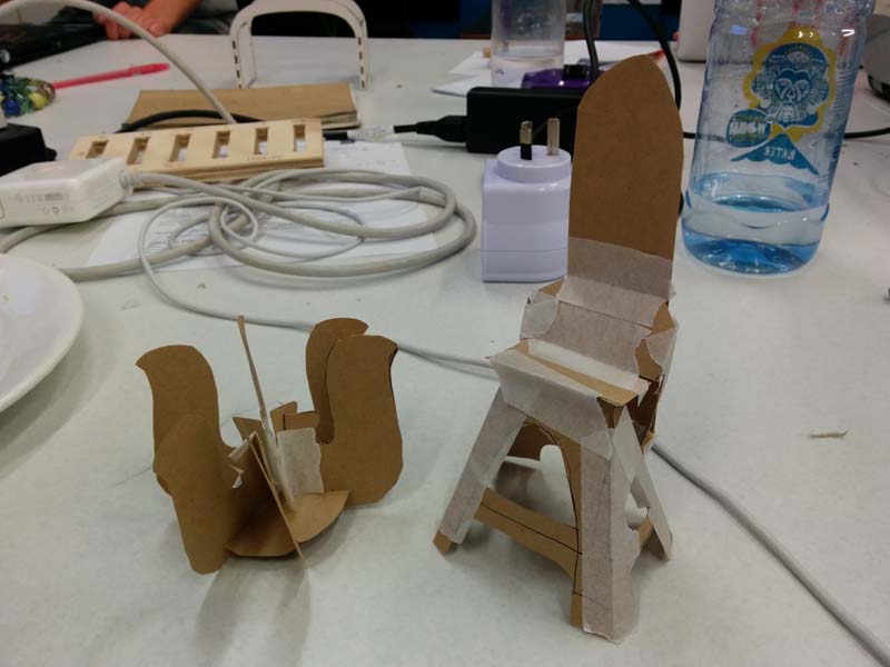
I decided to to make the bachelor chair. I didn’t have any previous furniture designing or building experience, but I was fascinated with the mechanics of the chair, and felt like the press fit aesthetic would make this old-fashioned piece more modern.
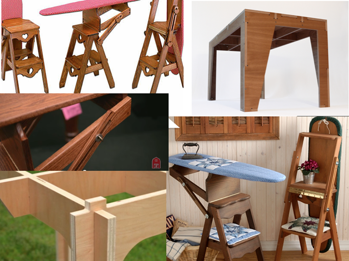
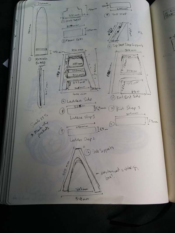
I made numerous sketches of the chair to wrap my head around the mechanics. I also took measurements of the bachelor chair at Fab Lab Wellington, which I would use as a starting point for my design.
Furniture Design in Illustrator
Once I had all the measurements, I went into Photoshop to design the parts. Despite having measurements to start with, there were aspects of the design of the bachelor chair that had to be re-considered because it will be cut out of plywood, not solid wood.
I was faced with 3 big design challenges:
My first attempt to solve all these challenges led to something that resembles more of a torture device than a bachelor chair. Wendy and Stu encouraged me to model it so I would be able to see how it would actually work.
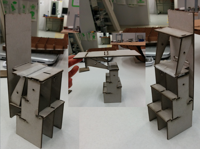
It was actually scarier as a model than as a blueprint. With the model, it was easy for Wendy to point out how unstable a square/rectangle structure would be, which seemed to make sense in 2D, but made very little sense in 3D. We also decided that because of the complexity of the bachelor chair mechanics, we would focus only on the base of the chair, which would be a chair on one side, and a step ladder on the other side.
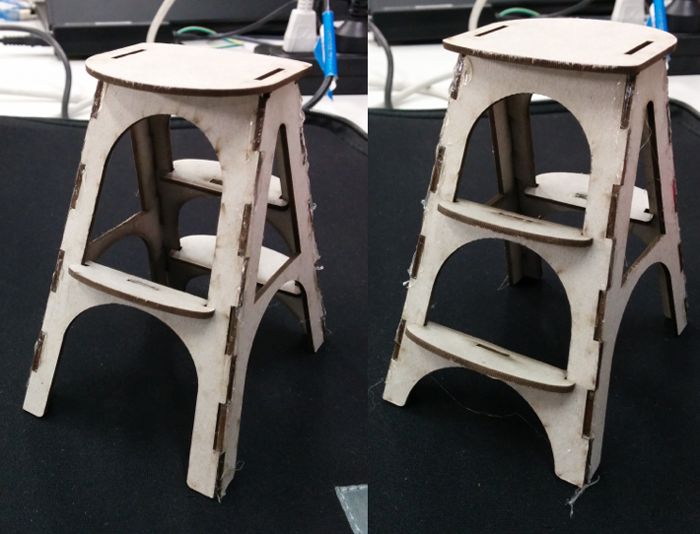
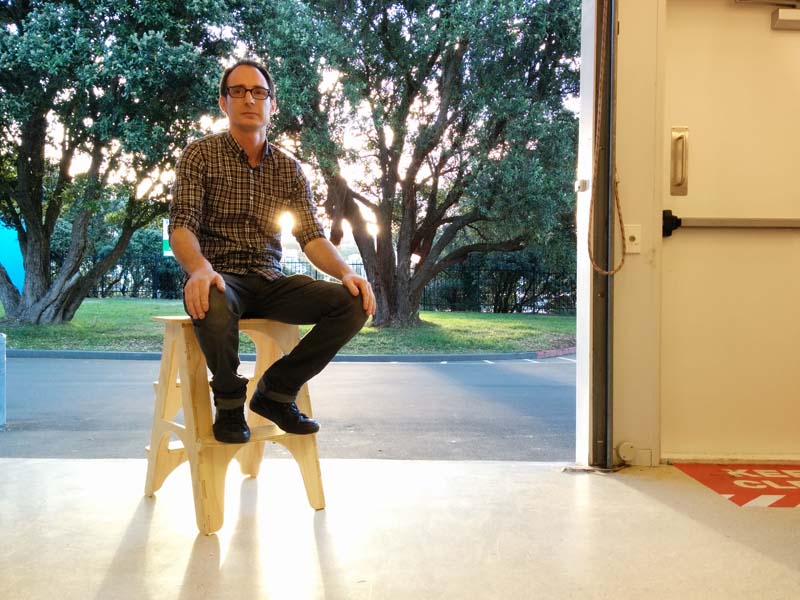
The new model was clearly more stable with nice proportions. The press-fit aesthetic suited this chair/ladder, making it look modern and functional and approachable, which was what I wanted.
I showed this design to other students, and the feedback that I got from Anna and Ted were on how the foot stool and the steps of the ladder tilted in at an 18* angle, rather than 90* angle from the ground. I refined my measurements in Illustrator and felt confident that after 2 models, I was ready to cut out the design on the Shopbot.
Shopbot Production
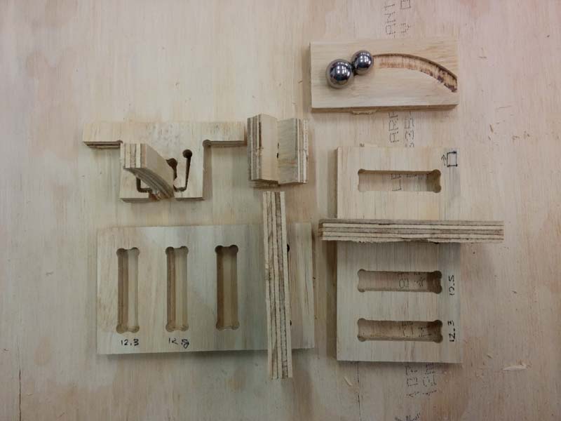
Anna and I worked on a joint test together. We were really surprised at the results - we were expecting a tolerance difference of 0.1 or 0.2 mm (like we saw with the laser cutter), but the best fit was actually at 0.5 mm. Prepping the joint test was good practice for cutting the actual assignments.
For this design, I decided on the following settings:
How to set-up PartWorks file:
Craig gave us good advice on how to set cut-depth for UP and Down cuts:
How to use the Shopbot
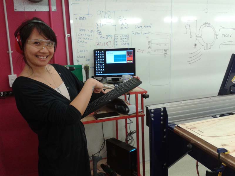
Wendy helped me a lot with this because there were quite a number of screw holes - both on and off the object, and I was unsure which ones to use. To speed up my process (as there were many undergrads waiting to use the machine), she showed me that I could start unscrewing the board, and pulling off parts while the Shopbot was on its final pass (while obviously paying attention to the Shopbot at all times, and being prepared to press the Stop button if the machine came too close to me.
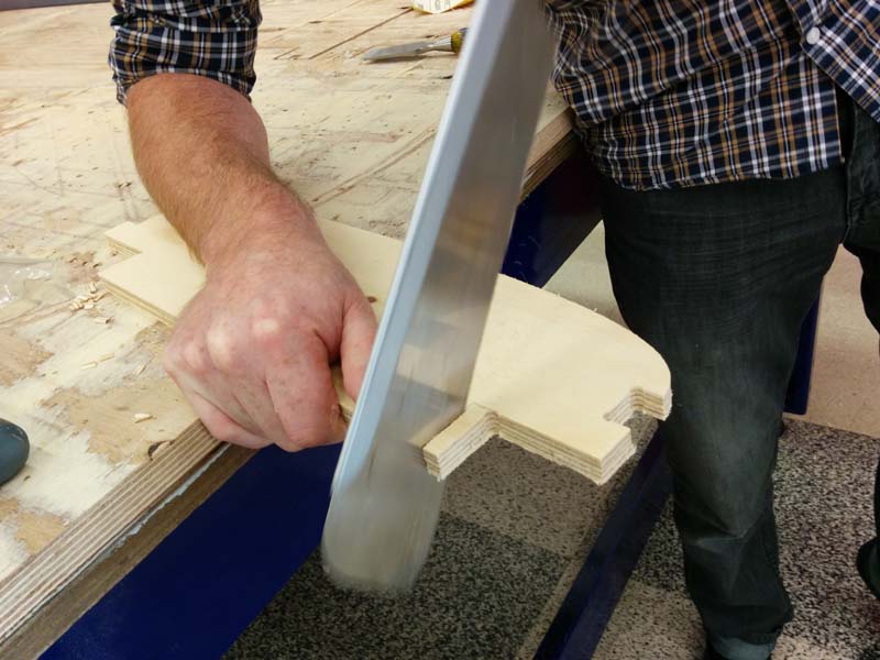
Stu helped me put the chair together using a mallet, a Japanese saw, a hammer, a chisel and some screws. It’s a proper press fit design. Unfortunately, I hadn’t taken dog bones into my design and the steps were just off. Also, I can’t use the chair as a step ladder as I originally hoped because the ladder tips over. But I’m happy with this as a first prototype and believe this is a good starting point for the bachelor chair.
You can download the DWG file here.
