(Milling) Moulding and Casting
In which I design a 3D mold of the Holdable Heart, machine it, and cast parts from it.
I make believe.
Design and build a wired &/or wireless network connecting at least two processors.
Servo Node Schematic and Board (Eagle) and Code (Arduino IDE)
Wellynet on Github
Wellynet development leads Daniel and Craig
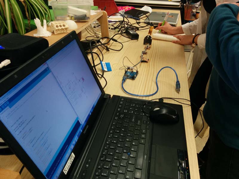
For this week’s assignment, Fab Lab Wgtn decided to team up and a Jargon-O-Meter! This is an activity that Wendy invented at this year’s Open Source Open Society conference, when she was running a workshop on open hardware. Here’s a video of Wendy’s real-life Jargon-O-Meter!
The digital version of the Jargon-O-Meter would allow the user to hit a big red button every time he/she hears jargon, which would trigger a series of connected devices to activate.
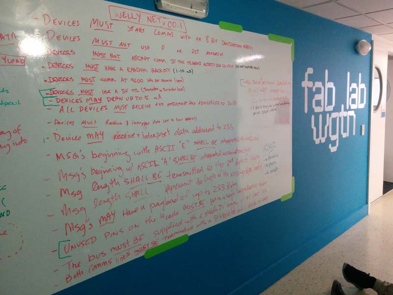
One of the challenges with this project was that we had to create a network that would allow our remote students to also participate. Daniel, who’s background is in network engineering, suggested that we develop a network protocol to govern the electronics and programming within our network. If you follow these specs, anyone can create a device that will work in the network. We call it… Wellynet.
Software:
Hardware:
Another important decision we made was what each pin of the header would be assigned to, so that when we connected each of the nodes, they would be passing the same data across the same pins.
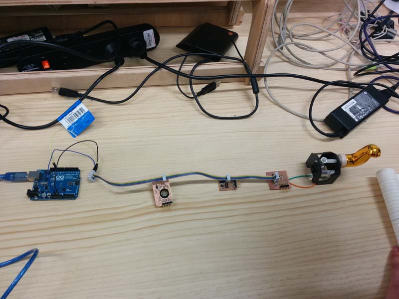
Reference Board Testing
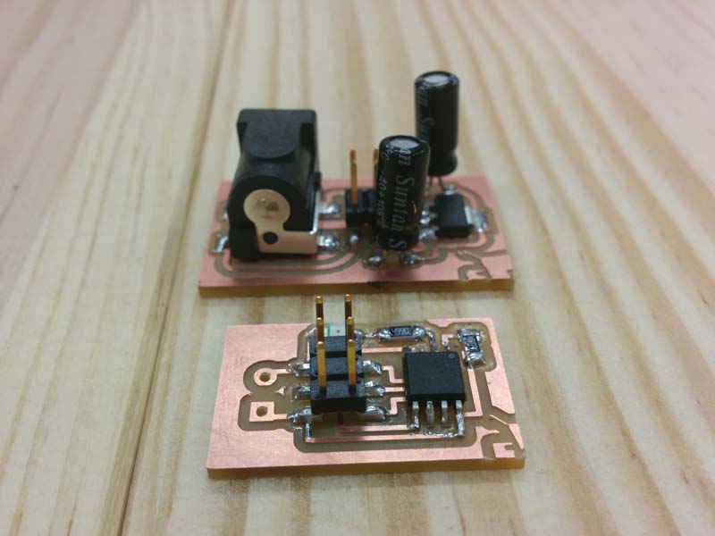
We decided to create a reference board to test the network. Geoff, Anna and I worked on the power board, which includes:
Craig and Daniel tested the minimum circuit for the network, and you read the results of their test here and here.
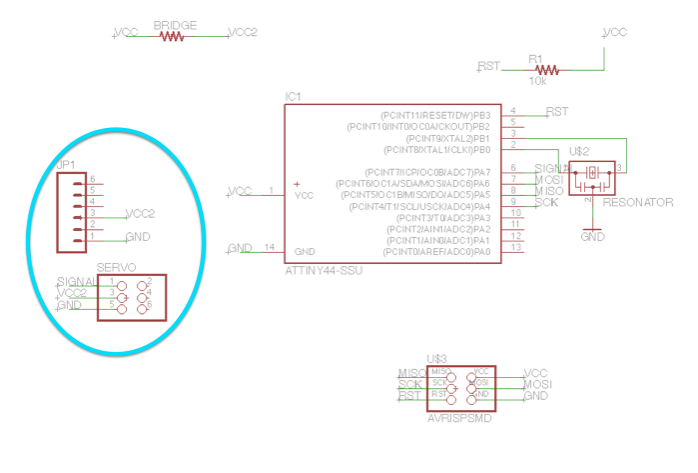
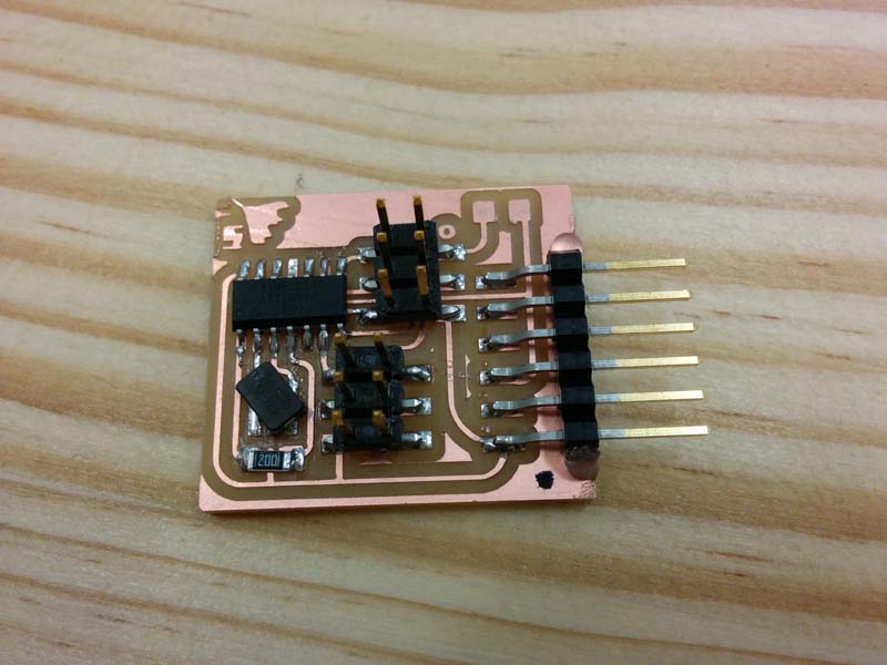
For my Node, I decided to start with the Servo motor board that I created in Week 12, but I had to provide power to the Servo that was separate from the power line to the network. This was one of the Wellynet protocols.
To do this, I had to create VCC2 which connected an FTDI cable to the servo. The standard FTDI Eagle library has VCC already named, and you cannot change it. To overcome this, I found a generic 6 pin header part under *M06*. I made sure that I was connecting the right pin to VCC and GND on a standard FTDI, and named the VCC pin as “VCC2”.
By separating the power source from the main network line, we created a new problem: how do we power the board while we are programming it?
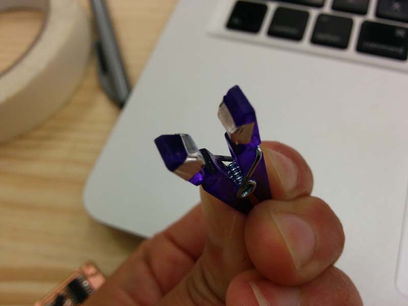
To overcome this, we created a bridge using a resistor on the board design, which connects VCC with VCC2. What we would do is when we are programming the board, we would use a removable clip with a connective tape on the ends to power the board. Once the board has been programmed, we can remove the clip and power the board with our own individual sources that are separate from the network line.
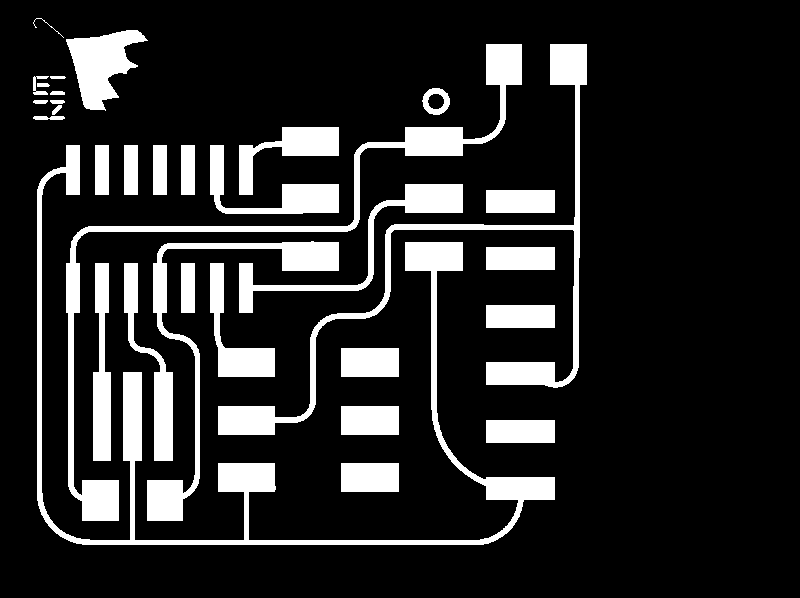
Here are the traces and board for the Servo Node board (not true size):

I connected my board to Arduino IDE and loaded up the Servo Sweep code that I had used in Week 12 as well as the test silicone mould I made for my Final Project. The servo buzzed around happily.
Daniel created a library for Wellynet that we could download in GitHub. I moved the library files into the library folder of Arduino IDE, and was able to reference it in my code.
The code can be separated into 2 parts:
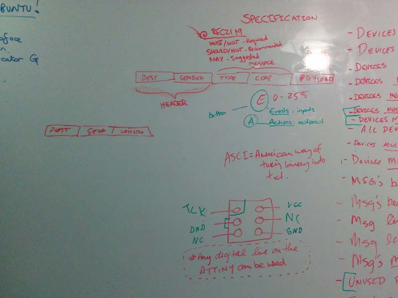
For communications, we referred back to the WellyNet protocol, which told us that the message would have the potential to be 10 numbers long and would follow this structure:
Craig discovered a function called myWelly.getPacket(theMessage) in Daniel's source code, which would make reading messages sent through the network more efficient by first checking to make sure that the message was the correct length. From there, we wrote code to find the letters "E" and "A" which we would then dispatch.
This is where Bry came in with a good idea to use the switch function that would allow us to create different cases for messages starting with "E" and "A". By using the switch function, we can potentially program our nodes to interact in a variety different actions and events across WellyNet.
As we were writing the code together, it suddenly dawned on me that the code I had to run the servo on an ATtiny44 was for a 1 mhz timer. As you may remember from Week 10, what a difficult time I had trying to find code that would servo code that would work for the ATTiny44. It basically came to someone's hack which could get the servo to work if the ATtiny was programmed at 1 mhz.
But Wellynet had to run on 20 mhz. And furthermore, my node board was designed with a 20 mhz resonator.
I tried to get around this by tweaking the pulse length and pulse timing in the servo code (for example, the 1 mhz code had a pulse length of 6000, so I multiplied that by 20 to 120000. No dice.
By this time, my Babeduino was finished, so I asked if I could use it as my node in networking, but Ben told me I couldn't because the Babeduino has a 20 mhz resonator, while Wellynet requires a 20 mhz crystal.
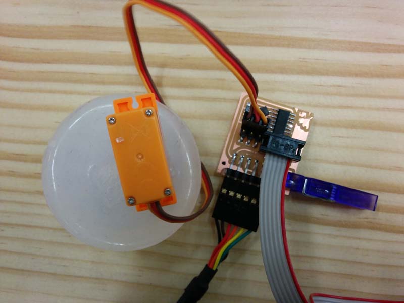
Finally, my solution was to replace the servo with a simple LED and a resistor. I did this by using a breadboard to break out the pins that were supposed to connect the servo to GND, VCC and PA7, and placed the LED between GND and PA7. I tested this using example Blink code and it was working, so I replaced my "dancing" code (that moves the servo) with "playing" code (that blinks the LED).
To test it out, I connected my node board to Anna's button, which we powered with an Arduino Uno. We used jumper cables to connect GND, 5V and SCK from the Arduino to Anna's and my board using the networking cable. When I pushed the button, my node started to "play" (LED blinking).
