Networking and Communications
The challenge:
Design and build a wired or wireless network connecting at least two processors.
Plan of attack:
Work with the rest of the class to design a specification for a simple wired network. Create a board that adheres to that specification and functions on our network.
Approach:
This week we decided to team up and try a slightly different approach to networking. As most of the group wasn’t intending to use networking as part of their final projects we thought it would be a fun excercise to go through designing a network specification and then trying to make boards that would work together. We we’re very luckily to have Daniel hanging out with us who has a massive amount of experience and was able to guide us through this process.
WellyNet v0.01
The first step in this exciting journey was to decide on our specification. Writing a spec was a really fun but actually quite challenging process. Initially we had to put enough in place that our system would actually work, but then once we had the basics covered other use cases would pop up. Someone would say “oh what about this” and we would have to consider both how we could deal with that situation but also how any new changes would impact on the ones we had already made. It was a really great exercise to work through. We wanted a network that could support multiple boards, so we opted to use a half duplex communication protocal. Using one line as our message line and another as a squelch line to avoide boards all sending communications at once. In the end we came up with about 20 rules in our protocal, but there are a few key decision we made that are worth highlighting.
Using an 6 pin ISP as the basis for our network. This would allow the potential for integrating with boards that we had already designed as well as other boards based on atmel hardware that we had lying around. It would also mean that our work was more likely to be useful to others in the future.
Using a 10 byte message length. By having a static length it made it easier to implement things like checksum and buffering. We we’re happy that the length would be enough for use cases we had designed the network for.
Using a single line for communication.
We named our protocol WellyNet.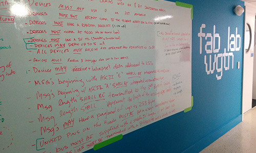
We split off into groups to start designing the network. I worked with Geoff and Ben to make a few reference boards. These were simple minimum circuits that we could use to demo functionality. We actually ended up making another iteration after having to alter our spec slightly to get a more reliable read as all our nodes were asynchronous.
We milled out all the boards and soldered them up.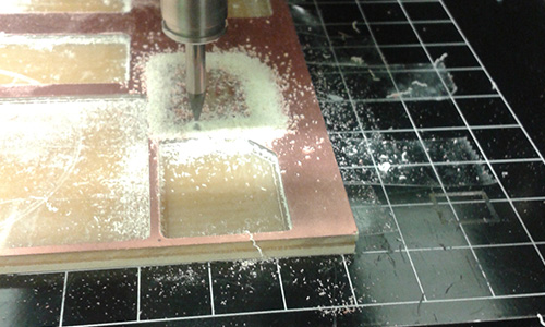
Meanwhile Anna and Daniel had been hard at work creating a library for us to use and were ready to do a basic test of the initial functionality.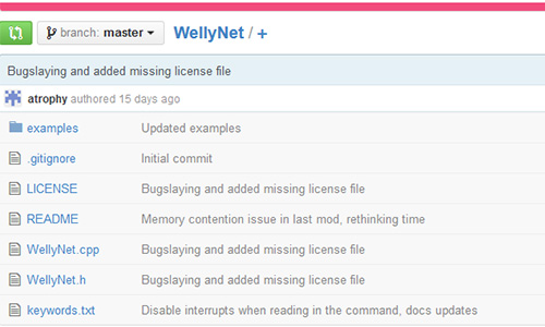
We hooked all the boards up and were ready to start our text but were having trouble getting the fuses to set. We kept running into a device signature error. Id run into the same problem back in week 11 and at the time had thought that I had managed to fry my chip. But this time round we were having the same problem on all three of the board that had just been milled. We went back to the schematic and triple checked every connection. Then got the multi meter out and have a good probe around for shorts or dodgy connections.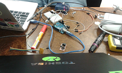
On a whim I tried swapping out the AVRISP we had been using and presto it worked. It was a relief because we were starting to run out of things to test but also a real pain to discover. A quick survey of the room showed that most people had run into the device signature error over the last few weeks, and due to our habit of just using what ever ISP happened to be close at hand had never attributed to source of the problem to the programmer rather than our boards. One collective sigh of frustration later we had successfully uploaded the first test code using the WellyNet library.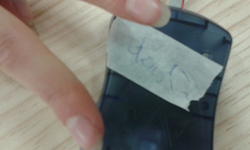
It even worked, sending packets of fun back down the line to be read by our serial converter.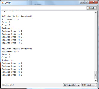
Give a voice to WellyNet
For my contribution to our network I elected to make a speaker that would play a short melody when triggered. Initially I whipped up a board based on the design I had done perviously in week 6. It was pretty enough and ready to mill but over dinner we got talking about potential ways to mount the speaker and board together to reduce its physical footprint.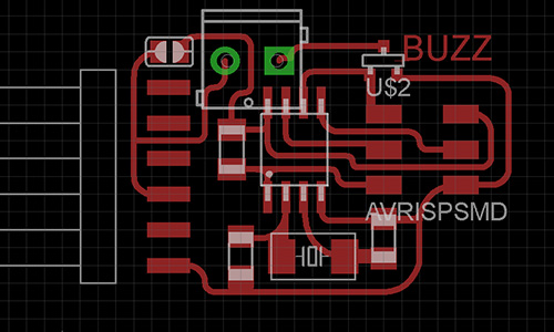
The solution I came up with was to design a new part in eagle, something I hadn’t done before. The part would include a cut hole in the center to allow the speaker to sit flush on the back of the board. Making parts in eagle is pretty straight forward but the main constraint is working with its super average drawing tools to actually get the shapes and spacing required. Once the symbol and device have been drawn the two can be linked up to form a device ready for use in the schematic.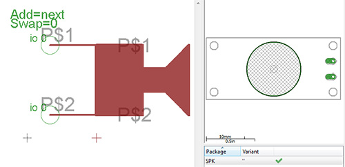
I set myself the challenge of trying to make the board fit inside the speakers footprint but it was actually quite challenging. All the legs wanted to go somewhere far away and over top of one another.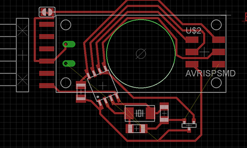
In the end I compromised slightly, extending out the side of the board to fit the traces, though this also provided me with room to add our awesome WellyNet logo that Anna had designed, based on an inside out umbrella. I also cheated and used inkscape to clean up the arcs running along one side of my board to make them look a little nicer.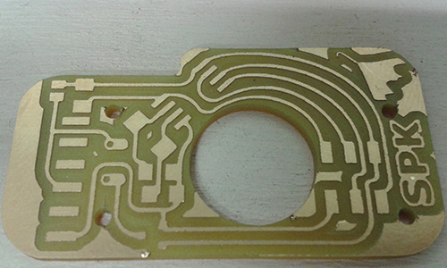
Then populated to board and mounted the speaker ready for testing.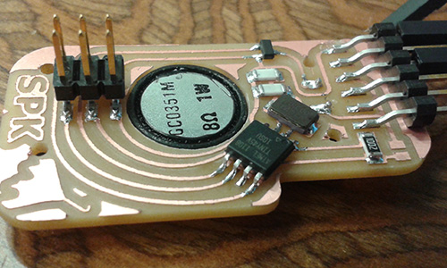
I hooked everything up and was able to send packets but there was a weird noise coming from my speaker. I disconnected it from the rest of the network and tried some tests, no buzzing. Reconnected to the rest of the network and the buzzing returned… Woops. I had left the speaker wired to my MISO line which had now become our talk line. So my speaker was effectively vocalizing WellyNet packets.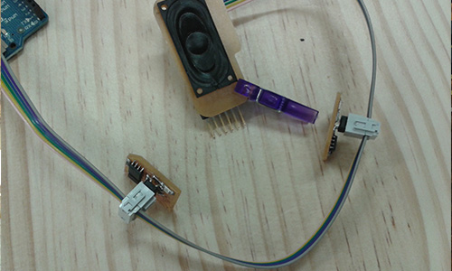
Back to the drawing board (also known as eagles schematic view) to whip up a new board. Luckily there were a few other changes I was looking to make so this would be a good opportunity to try them out. The main changes were: Swapping in an Attiny 44 to provide the extra pins required to run the speaker. Ditching the screw holes for the speaker mount and increasing the size of the mount hole slightly. Changing the way the speaker was wired up to increase the volume and decrease the heat it was generating.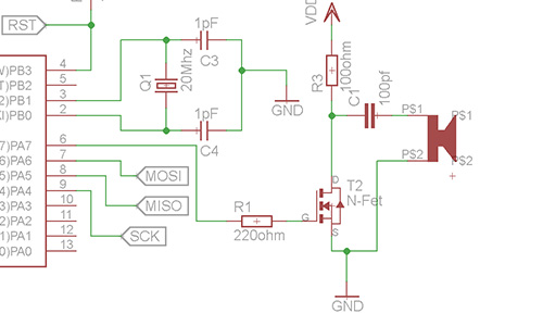
To my surprise after milling, populating and programing the board the speaker was actually quieter than before. Bry was hanging out in the lab that evening and gave me a hand adding an additional probe to our scope to test how fast the cap was charging and discharging as the speaker played.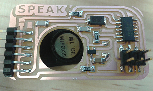
The graph below shows the results when I first tested the board. The cap charges very quickly but it also discharges very quickly resulting in very quite noise. By increasing the size of the cap I was able to prolong the discharge time and increase the volume of the speaker.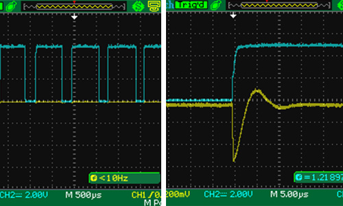
With the new board singing happily I added it back into the network and it worked. When Anna triggered her button my board would play its song. The 44 chip had a crazy limited amount of space and anything with audio tends to gobble it up quickly. My code in combination with the WellyNet library used 98% of the available space. So it might be worth looking into the Attiny84 chips if this was going to be used for any serious project.
This weeks project was a massive group effort and we couldn’t of done it without the all the effort from everyone. Nice work guys. Check out our class project page for more information and each of my classmates sites, linked below, to see what they got up to.
Networking - Weekly resources
Tools used this week:
Hardware:
Materials:
See eagle files for BOM
Tutorials links or references used
Files Produced
Archived files
WellyNet on GitHub